Abstract
Fiber-reinforced polymer (FRP) composites, particularly glass fiber-reinforced polymer (GFRP), are increasingly utilized in civil engineering due to their high strength-to-weight ratio, corrosion resistance, and environmental sustainability compared to steel. Shear connectors in FRP–concrete hybrid beams are critical for effective load transfer, yet their behavior under static loads remains underexplored. This study aims to investigate the shear strength, stiffness, and failure modes of GFRP, CFRP, AFRP, and stainless-steel shear connectors in FRP–concrete hybrid beams through a comprehensive parametric analysis, addressing gaps in material optimization, bolt configuration, and design guidelines. A validated finite element model in Abaqus was employed to simulate push-out tests based on experimental data. The parameters analyzed included shear connector material (GFRP, CFRP, AFRP, and stainless steel), bolt diameter (16–30 mm), number of bolts (1–6), longitudinal spacing (60–120 mm), embedment length (40–70 mm), and concrete compressive strength (30–70 MPa). Shear load–slip (P-S) curves, ultimate shear load (P), secant stiffness (K1), and failure modes were evaluated. CFRP bolts exhibited the highest shear capacity, 26.50% greater than stainless steel, with failure dominated by flange bearing, like AFRP and stainless steel, while GFRP bolts failed by shear failure of bolt shanks. Shear capacity increased by 90.60%, with bolt diameter from 16 mm to 30 mm, shifting failure from bolt shank to concrete splitting. Multi-bolt configurations reduced per-bolt shear capacity by up to 15.00% due to uneven load distribution. Larger bolt spacing improved per-bolt shear capacity by 9.48% from 60 mm (3d) to 120 mm (6d). However, in beams, larger spacing reduced the total number of bolts, decreasing overall shear resistance and the degree of shear connection. Higher embedment lengths (he/d ≥ 3.0) mitigated pry-out failure, with shear capacity increasing by 33.59% from 40 mm to 70 mm embedment. Increasing concrete strength from 30 MPa to 70 MPa enhanced shear capacity by 22.07%, shifting the failure mode from concrete splitting to bolt shank shear. The study highlights the critical influence of bolt material, diameter, number, spacing, embedment length, and concrete strength on shear behavior. These findings support the development of FRP-specific design models, enhancing the reliability and sustainability of FRP–concrete hybrid systems.
1. Introduction
Fiber-reinforced polymer (FRP) composites have become pivotal in modern civil engineering due to their superior mechanical performance and environmental advantages over conventional steel. Characterized by high strength-to-weight ratios, exceptional corrosion resistance, design versatility, and enhanced sustainability [1,2], FRP materials—such as glass fiber-reinforced polymer (GFRP), carbon fiber-reinforced polymer (CFRP), and aramid fiber-reinforced polymer (AFRP)—offer a viable and eco-friendly alternative to steel, whose production is associated with high energy consumption and significant carbon emissions [3,4]. In FRP–concrete composite beams, shear connectors play a critical role in transferring interfacial shear stresses between the FRP profile and the concrete slab, thereby ensuring full composite action, structural integrity, and serviceability [5,6]. Research has shown that the arrangement of shear connectors, such as studs, significantly affects the fatigue behavior of composite beams under cyclic loading, underscoring the importance of optimized connector designs for enhanced durability [7]. Furthermore, parametric studies on strengthening steel–concrete composite beams with carbon fiber tendons demonstrate improved shear capacity and structural efficiency, suggesting potential applications of advanced composite materials in FRP–concrete hybrid systems [8].
Researchers have developed FRP–concrete hybrid sections, where a thin-walled FRP element is combined with a concrete slab, forming a cost-effective and structurally efficient system. These FRP–concrete composite beams effectively exploit the advantages of both materials—concrete in compression and FRP in tension—resulting in low maintenance requirements, enhanced flexural performance, ease of installation, and excellent durability in harsh environments, particularly for bridge applications [2]. Field applications of FRP–concrete hybrid bridges have been demonstrated globally. The first was the Miyun Bridge in Beijing (1982), a structure spanning 20.7 m that was initially made of GFRP box girders, and it was later converted to an FRP–concrete hybrid beam bridge with a 100 mm concrete slab and steel bolt connectors [9]. In Australia (2002), a 12 m bridge with rectangular GFRP beams and bonded CFRP laminates was built, followed by two U-girder hybrid bridges in Texas (2005–2007) that remain in excellent condition [10,11]. In Spain (2004–2007), several hybrid bridges using CFRP or GFRP/CFRP girders and concrete slabs were rapidly assembled and have shown long-term durability without maintenance issues [12,13]. Other examples include a cable-stayed-like pedestrian bridge and an arch bridge in China using pultruded GFRP beams, both exhibiting satisfactory stiffness and vibration comfort. Additionally, the Ryjak River Bridge in Poland, a 22 m FRP–concrete hybrid bridge, features FRP girders with a concrete slab. Its design combines carbon and glass fibers and PVC foam, enabling rapid assembly within two hours. Dynamic testing confirmed that hybrid FRP–concrete beams provide better damping and dynamic behavior than all-FRP bridges [14,15,16].
Various types of shear connectors—epoxy bonding, perforated FRP ribs (PFR), composite dowels, headed suds, and bolts—are utilized in composite beams in practice [17]. Although epoxy bonding is easy to apply without causing damage to the concrete or fiber-reinforced polymer (FRP), its shear strength is low, and its quality is uncontrollable because of voids that result from uneven application. It is also susceptible to environmental deterioration. Epoxy bonding is typically appropriate for temporary bridges [18,19]. PFR has the properties of high shear strength, stiffness, and ease of construction. However, PFR is more prone to shear failure at the web of perforated ribs because of the lower interlayer shear strength of FRP. PFR is commonly applied in large-span hybrid beams and slabs [20]. Composite dowels have been developed as shear connectors in composite beams, offering uniform shear force distribution and improved fatigue resistance due to their symmetric geometry and radius connections, but they face limitations such as susceptibility to concrete shear or pry-out failures and reduced strength in cracked concrete [21,22,23]. Headed studs are the most common shear connectors in composite structures, providing longitudinal shear resistance and preventing slab uplift [24]. Their installation requires specialized welding, but welds can suffer fatigue under cyclic loads [25,26]. Bolts in FRP–concrete connections are prone to environmental erosion, prompting the use of stainless steel or GFRP bolts [6]. While stainless steel offers high shear strength and ease of installation, it can cause bearing failures in GFRP bolt holes. GFRP bolts provide corrosion resistance, higher tensile strength, and better utilization of bolt capacity with minimal impact on overall performance [27,28,29]. Although promising, FRP shear connector behavior is insufficiently characterized, and major gaps exist in the understanding of their behavior under different design parameters, calling for detailed parametric studies.
Research on shear connectors for FRP–concrete hybrid beams has examined epoxy bonding, PFR, and bolts, with PFR and bolts found to be more reliable than epoxy bonding [30,31,32]. Extensive studies on PFR have developed calculation methods for ultimate shear strength and P-S models [32,33], while research on bolts has mainly focused on stainless steel. Push-out tests on three steel bolt specimens showed that higher concrete strength and larger bolt diameters increased shear capacity [34,35]. Twelve additional push-out tests on stainless-steel bolts in FRP–ultra-high-performance concrete (UHPC) hybrid beams revealed that the effective depth-to-diameter ratio (hef/d) governs failure modes, ranging from pry-out to FRP compression, concrete cracking, and bolt shear failure [29]. Fourteen push-out tests demonstrated that UHPC prevents concrete compression failure and improves shear strength in specimens with high-strength steel bolts [36]. Furthermore, six push-out tests indicated that increasing bolt diameter can raise capacity by up to 29.4% [37]. Despite the substantial research on stainless-steel bolts, work on FRP bolt shear connectors remains limited. Tests on GFRP bolts have shown that their ultimate strength is reduced by the combined effects of bending and shear [38], while push-out tests on two specimens with GFRP bolts revealed linear P-S curves up to the point of shear failure [29]. Thirty push-out tests on GFRP bolts identified three failure modes—bolt shank shear, pry-out, and concrete splitting—compared to only bearing failure in stainless-steel bolts. GFRP P-S curves exhibited micro-slipping and significant-slipping phases [27].
Due to the scarcity of data, no standard design equations are currently available for FRP bolts, leading to reliance on preliminary laboratory results and engineering judgment, which can result in conservative designs and reduced practical use. Conversely, the steel–concrete composite beam system has benefited from extensive study and established design equations for studs [39,40], though their suitability for FRP bolts remains unconfirmed due to material property differences. Previous investigations have identified critical knowledge gaps in the behavior of FRP shear connectors. These include the limited examination of alternative FRP types beyond GFRP (e.g., CFRP, AFRP), insufficient parametric analyses addressing bolt spacing and number in multi-bolt systems, the absence of accurate shear capacity models accounting for the anisotropic nature of FRPs, and restricted experimental data across a broad range of concrete compressive strengths.
This study undertakes a comprehensive parametric investigation of FRP shear connectors in FRP–concrete hybrid beams with the following objectives: (i) comparing the shear strength, stiffness, and slip behavior of GFRP, CFRP, AFRP, and steel bolts for corrosion-resistant and sustainable structural applications; (ii) quantifying the influence of bolt diameter, number, and spacing on shear transfer efficiency, stiffness, and failure modes; (iii) assessing the role of embedment length in preventing brittle concrete failures; and (iv) evaluating connector performance under varying concrete compressive strengths. This research seeks to develop scientifically sound, FRP-related models that strengthen design codes so that FRP–concrete hybrid systems for aggressive structural applications are assured of structural reliability, durability, and environmental sustainability.
2. Finite Element Analysis
A finite element (FE) model was developed using Abaqus to validate the experimental push-out test results for glass fiber-reinforced polymer (GFRP) and stainless-steel bolt shear connectors in fiber-reinforced polymer (FRP)–concrete hybrid beams, as reported by [27]. This section verifies the FE model by simulating three representative specimen groups: FB-1 to FB-3 (shear failure of GFRP bolt shank), SB-1 to SB-3 (bearing failure of GFRP flange), and FB-25 to FB-27 (concrete splitting failure). The model was evaluated against experimental shear load–slip curves (P-S) and failure modes presented in [27]. The following subsections detail the model geometry, material properties, interactions, simulation, failure modes, mesh sensitivity analysis, and validation results.
2.1. Geometry
The FE model geometry replicates the push-out test specimens detailed in [27], as shown in Figure 1. Each specimen consisted of a GFRP-pultruded profile connected to two symmetric concrete slabs via bolts. The GFRP profile was modeled as a three-dimensional (3D) solid with a cross-section matching the experimental specifications, comprising a web and flanges. The concrete slabs measured 500 mm (length) × 300 mm (width) × 85 mm (thickness). Each concrete slab was reinforced with GFRP bars of 9.5 mm diameter [27].
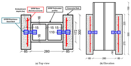
Figure 1.
Details of the tested push-out specimens.
Two configurations of specimens were selected in this analysis. The first bolt configuration was in the identical specimens FB-1 to FB-3, which consisted of GFRP bolts with a 20 mm diameter and a 60 mm embedment depth (he/d = 3.0), arranged with one bolt per side in a 1 × 1 configuration, as illustrated in Figure 2a. Stainless-steel bolts with the same 20 mm diameter and 60 mm embedment depth (he/d = 3.0), arranged in a 1 × 1 configuration, were analyzed. The second bolt configuration was in specimens FB-25 to FB-27, which employed GFRP bolts with a larger diameter of 24 mm and the same 60 mm embedment depth (he/d = 2.5), but arranged with four bolts per side in a 2 × 2 configuration, as presented in Figure 2b.
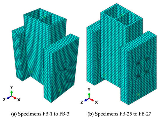
Figure 2.
FE mesh and different components of the FE models.
2.2. Material Properties
Material properties were derived from experimental data in [27] and supplemented with standard values for Abaqus compatibility. The properties for each material are presented in the following tables.
2.2.1. Concrete
Concrete was modeled using the concrete damaged plasticity (CDP) model in Abaqus to capture nonlinear behavior. The mechanical properties of concrete were determined in accordance with GB/T 50081–2019 [41], and CDP parameters were based on [42]. The properties are listed in Table 1. The adopted stress–strain relationships for concrete in tension and compression are shown in Figure 3.

Table 1.
Concrete material properties.
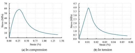
Figure 3.
Stress–strain curves of concrete.
2.2.2. GFRP-Pultruded Profile
The GFRP-pultruded profile was modeled as an orthotropic material with distinct properties for the web and flanges. Properties were assigned separately for web and flange elements in Abaqus, based on experimental data from [27]. Properties are detailed in Table 2.

Table 2.
GFRP-pultruded profile material properties.
2.2.3. GFRP Reinforcement Bars
The GFRP reinforcement bars, embedded in the concrete slabs, were modeled as isotropic to simplify tensile reinforcement simulation. Properties were based on experimental data from [27]. Properties are given in Table 3.

Table 3.
GFRP reinforcement bar material properties.
2.2.4. GFRP Bolts
The GFRP bolts were modeled as orthotropic materials to capture anisotropic behavior under shear-dominated failure. Properties for FB-1 to FB-3 (20 mm diameter) and FB-25 to FB-27 (24 mm diameter) are shown in Table 4. Properties were based on experimental data from [27].

Table 4.
GFRP bolt material properties.
2.2.5. Stainless-Steel Bolts
The stainless-steel bolts (SB-1 to SB-3) were modeled as isotropic elastoplastic materials for nonlinear analysis in Abaqus. Bi-linear stress–strain relationship was adopted for stainless steel. Properties, listed in Table 5, were based on experimental data from [27].

Table 5.
Stainless-steel bolt material properties.
2.2.6. Stress–Strain Relationship of GFRP and Stainless Steel
The stress–strain behavior of GFRP and stainless steel is critical in determining the mechanical response of FRP–concrete hybrid beams. GFRP has an elastic behavior until failure, which reflects its brittle fracture mechanism and orthotropic behavior, because its mechanical properties vary widely in different directions: longitudinal and transverse, depending on the fiber orientation and matrix composition. Therefore, an elastic constitutive model for GFRP was used, which was consistent with the reported experimental and numerical studies [27,35,43]. On the other hand, stainless steel behaves like an isotropic elastoplastic material, which is characterized by gradual yielding and a strain-hardening stage. Therefore, the bi-linear stress–strain model was used to quantify the elastic–plastic transition. This model represents well the behavior of stainless steels that have high ductility and high work-hardening capacity [27,44,45].
2.3. Interactions
In the FE model, the interaction between GFRP reinforcement bars and concrete slabs was simulated using Abaqus’ embedded element constraints, assuming perfect bond, which is consistent with common reinforcement modeling practices [46]. The concrete–GFRP interface was represented by a surface-to-surface contact definition with hard contact for the normal behavior and a penalty friction formulation with a coefficient of 0.5, following typical modeling approaches for concrete–GFRP interfaces [47,48]. For the bolt–GFRP flange interaction, a surface-to-surface contact was defined between the bolt shank and the GFRP flange hole, employing hard contact in the normal direction to prevent penetration and ensure non-overlapping surfaces. A relatively high friction coefficient of 0.45 was adopted to account for the enhanced surface roughness and the mechanical interlocking produced by the threads and nut tightening at the clamped interface. This approach provides a conservative representation of shear transfer. The contact surfaces between the GFRP bolt and flange were assumed to be threaded and surface-abraded, leading to increased interfacial friction and confinement. The selected value, while neglecting detailed thread geometry to reduce computational cost, was calibrated based on previous experimental and numerical studies [49,50,51] and validated against push-out test results [27]. Similarly, bolt–concrete interaction was modeled using surface-to-surface contact between the bolt shank and the concrete slab, with hard contact in the normal direction and a penalty friction formulation with a coefficient of 0.55 for tangential behavior. The embedded bolt threads were also omitted in this case, and the friction coefficient was calibrated to be sufficiently large to hold the bolts in place and to ensure close agreement between the numerical and experimental load–response curves. The selected friction coefficient aligns with values reported in the literature for similar interfaces [47,48,49,52,53].
2.4. Loading and Boundary Conditions
The loading protocol was defined to replicate the experimental setup described in [27]. A displacement-controlled vertical load (U2) was applied downward to the top surface of the GFRP-pultruded profile. Kinematic boundary conditions were imposed to simulate the experimental constraints. The bottom surfaces of both concrete slabs were fully restrained in all translational and rotational degrees of freedom (U1 = U2 = U3 = UR1 = UR2 = UR3 = 0), where U1, U2, and U3 denote displacements in the global X-, Y-, and Z-directions, respectively, and UR1, UR2, and UR3 represent rotations about these axes. This condition reproduced the rigid support provided by the steel platform with fine sand leveling. For the GFRP-pultruded profile, the top surface was permitted to translate in the vertical direction (U3) to enable load application, while lateral displacements (U1, U2) and all rotations (UR1, UR2, UR3) were constrained to prevent out-of-plane movement and ensure stability during loading.
2.5. Mesh Sensitivity Analysis
The finite element model utilized specific element types to represent the components of the FRP–concrete hybrid beam system in Abaqus. The GFRP-pultruded profile, concrete slabs, GFRP bolts, and stainless-steel bolts were modeled using three-dimensional 8-node linear elements with reduced integration (C3D8R), chosen for their computational efficiency and ability to capture three-dimensional stress states. Because the interaction between the bolts and the GFRP-pultruded profile has a significant influence on the connection’s ultimate strength, shell elements were deemed unsuitable for modeling the GFRP profile [49,54]. GFRP reinforcement bars embedded in the concrete slabs were modeled using three-dimensional 2-node linear truss elements (T3D2), which are well-suited for simulating uniaxial tensile behavior while simplifying reinforcement representation [49,54]. This combination of C3D8R for solid components and T3D2 for reinforcement ensured accurate structural behavior modeling while optimizing computational performance.
The experimental shear load for FB-1 to FB-3 was calculated by averaging the three specimens; the reference experimental peak shear load is 67.90 kN [27]. Results are presented in Table 6 and Figure 4.

Table 6.
Mesh sensitivity analysis results for FB-1 to FB-3 specimens.
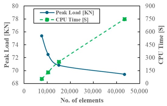
Figure 4.
Mesh sensitivity analysis results for FB-1 to FB-3 specimens.
Mesh 1 (10 mm) provided the highest accuracy (69.42 kN, +2.24% error) but required 750 min on a 16-core CPU. Mesh 2 (15 mm) reached 70.82 kN (+4.30% error) with a computation time of 252 min. Mesh 3 (20 mm) overestimated the peak load (72.50 kN, +6.77% error). Mesh 4 (25 mm) produced the largest deviation (75.40 kN, +11.05% error); this overestimation may be due to modeling/mesh localization and numerical effects associated with coarse discretization rather than improved resolution of stress concentrations. In all four cases, smaller mesh sizes are used in critical regions to improve stress concentration resolution. Mesh 2 was selected for all simulations as it balances accuracy and computational efficiency.
2.6. Validation Results
The FE model was analyzed using Abaqus with a nonlinear static general step. Simulated P-S curves and failure modes for FB-1 to FB-3, SB-1 to SB-3, and FB-25 to FB-27 were compared with experimental results in [27]. The experimental shear load for each group was calculated by taking the average of the three laboratory-tested specimens. Average ultimate shear loads per bolt (P), relative mean slip corresponding to P (S), and average secant stiffness of bolt in a group (K1) are shown in Table 7 and Figure 5.

Table 7.
Validation results for shear load and error.
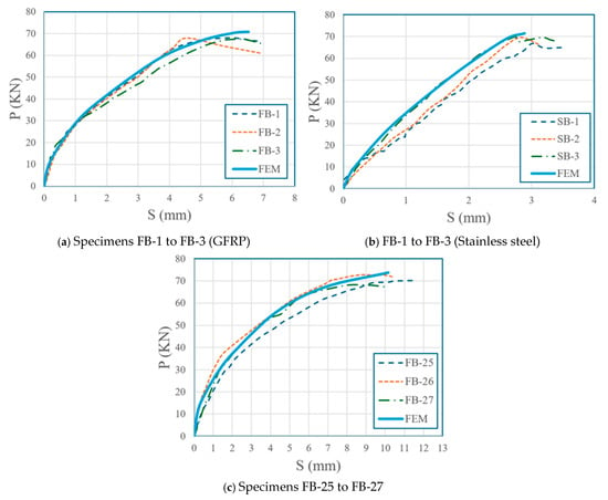
Figure 5.
Load–slippage relationships.
The simulated failure modes closely aligned with experimental observations reported in [27]. For FB-1 to FB-3, failure occurred due to shear failure of the GFRP bolt shank, with the shear stress reaching the transverse shear strength of the GFRP bolts (227 MPa; Figure 6). For SB-1 to SB-3, failure was characterized by bearing failure of the GFRP flange, where the longitudinal compressive stress attained the longitudinal compressive strength of the GFRP flange (235 MPa; Figure 7). For FB-25 to FB-27, failure occurred by concrete splitting, with the tensile stress in the concrete reaching its tensile strength (3.91 MPa; Figure 8). The shear load–slip (P-S) curves for GFRP bolts exhibited two distinct phases (micro-slipping and significant slipping), while stainless-steel bolts displayed linear behavior, which is consistent with experimental results in [27]. Shear stiffness at 0.2 mm and 1.0 mm slip showed errors within 6%, confirming model accuracy in both elastic and plastic regimes.
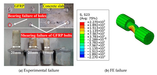
Figure 6.
Experimental and FE shear failure comparison of the GFRP bolt shank (FB-1~FB-3).
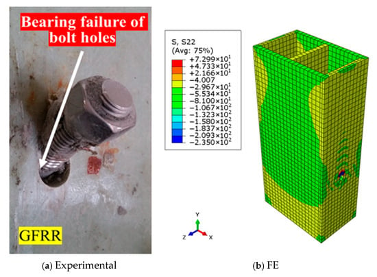
Figure 7.
Bearing damage of the GFRP flange (SB-1~SB-3).
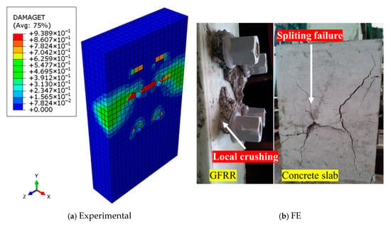
Figure 8.
Concrete splitting failure (FB-25~FB-27).
3. Parametric Study
This section presents the results of the parametric study performed with the validated finite element (FE) model in Abaqus, as described in Section 2. The study examines shear load–slip (P-S) curves, normalized ultimate shear load per bolt, and failure modes for shear connectors in FRP–concrete hybrid beams under variations in shear connector material (GFRP, CFRP, AFRP, and stainless steel), bolt diameter, number of bolts, bolt spacing, embedment length, and concrete compressive strength. Each subsection discusses the P-S behavior, ultimate shear load, and failure criteria. Shear stiffness values are reported at slips of 0.2 mm and 1 mm, and failure modes include bolt shank shear, bearing failure of the GFRP flange, concrete splitting, and pry-out failure, classified according to [27].
3.1. Effect of the Shear Connector Material
Four materials were tested in a 2 × 2 configuration with 120 mm longitudinal row spacing, 80 mm horizontal spacing, 20 mm diameter bolts, 60 mm embedment depth, and concrete compressive strength of 57.8 MPa. The material properties for the shear connectors, defined for numerical modeling in Abaqus, are presented in Table 8. FRP bolts (GFRP, CFRP, and AFRP) were modeled as orthotropic to capture anisotropic behavior. Stainless-steel bolts were modeled as isotropic elastoplastic with a von Mises yield criterion for nonlinear analysis.

Table 8.
Shear connector material properties for Abaqus modeling.
The material properties for the shear connectors are presented in Table 8. GFRP properties correspond to E-glass fibers with a ±45° surface wrap via pultrusion, ensuring high transverse shear strength. CFRP properties align with T700 carbon fibers produced by filament winding, reflecting their superior tensile strength. AFRP properties represent Kevlar 49 fibers via pultrusion, with moderate mechanical performance. Stainless steel properties are based on the standard of 304 A2-50 [27,55,56,57,58].
The P-S curves exhibited two phases for FRP materials (micro-slipping and significant slipping) and linear behavior for stainless steel, which is consistent with [27]. Table 9 and Figure 9 summarize the results.

Table 9.
Ultimate shear load and failure modes for different shear connector materials.
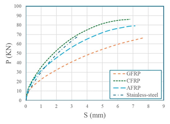
Figure 9.
Effect of the shear connector material on P-S curves.
CFRP bolts achieved the highest shear capacity (86.07 KN), 26.50% higher than stainless steel (68.04 KN). AFRP bolts (79.19 KN) outperformed GFRP bolts (66.38 KN) by 19.30%. GFRP bolts failed by bolt shank shear due to their lower elastic modulus, and its lower transverse shear strength (227 MPa) compared to the GFRP flange’s compressive strength (235 MPa), while CFRP, AFRP, and stainless-steel bolts failed by flange bearing due to their higher transverse shear strength and elastic modulus. Additionally, these bolts are considerably stiffer and stronger than the surrounding GFRP flange; the compressive stresses concentrate at the bolt–flange interface, leading to localized crushing or deformation of the flange hole, resulting in failure at the GFRP profile. The deformation of stainless-steel bolts was the least among all tested materials, due to its much higher elastic and shear modulus. As a result, the shear stiffness of stainless-steel bolts was the highest, which also contributed to its minimal deformation.
3.2. Effect of the Bolt Diameter
GFRP bolts were tested with diameters of 16 mm, 20 mm, 24 mm, and 30 mm, with 60 mm embedment length and concrete strength of 57.8 MPa in a 2 × 2 configuration with 120 mm longitudinal row spacing and 80 mm horizontal spacing. It was assumed that the mechanical properties of GFRP bolts were identical for all tested diameters. Results are shown in Table 10 and Figure 10. Shear capacity increased with diameter due to greater cross-sectional area, with the 30 mm bolt achieving 81.62 KN, which is 90.60% higher than the 16 mm bolt (42.82 KN). The 24 mm and 30 mm bolts exhibited higher loads but shifted to concrete splitting due to exceeding the concrete’s bearing capacity.

Table 10.
Ultimate shear load and failure modes for different bolt diameters.
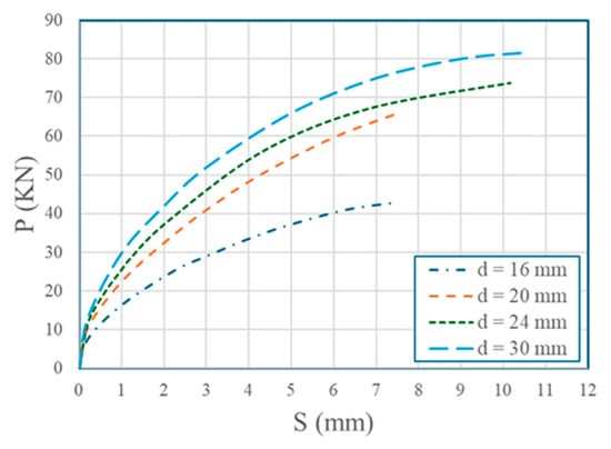
Figure 10.
Effect of the bolt diameter on P-S curves.
3.3. Effect of the Number of Bolts
GFRP bolts with 20 mm diameter and 60 mm embedment length were tested in 1 × 1, 1 × 2, 2 × 2, and 3 × 2 configurations with 120 mm longitudinal row spacing, 80 mm horizontal spacing, and 57.8 MPa concrete strength. Results are presented in Table 11 and Figure 11. All configurations predominantly failed by shear failure of the GFRP bolt shanks, except for the 3 × 2 configuration, which exhibited concrete slab splitting. The average per-bolt shear capacity decreased with an increasing number of bolts, from 70.82 KN for the 1 × 1 configuration to 60.20 KN for the 3 × 2 configuration, representing a 15.00% reduction. The 1 × 2 and 2 × 2 bolt configurations exhibited lower per-bolt shear capacity than the single-bolt (1 × 1) configuration due to group effects, where adjacent bolts caused non-uniform load distribution and stress interaction in the surrounding concrete. In the 3 × 1 configuration, although the ultimate shear load per bolt decreased due to stress overlap, the total ultimate shear load increased owing to the greater number of bolts contributing to shear transfer. Consequently, the concrete became the weaker component, and failure occurred by slab splitting rather than GFRP bolt shear.

Table 11.
Ultimate shear load per bolt and failure modes for different bolt numbers.
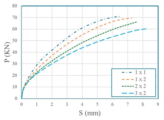
Figure 11.
Effect of the number of bolts on P-S curves.
3.4. Effect of the Longitudinal Spacing Between Bolts
GFRP bolts with 20 mm diameter and 60 mm embedment length in a 2 × 2 configuration were tested with longitudinal row spacings of 60 mm (3 d), 80 mm (4 d), 100 mm (5 d), and 120 mm (6 d), in a rectangular arrangement with 80 mm horizontal spacing, as shown in Figure 12, using 57.8 MPa concrete. The results are in Table 12 and Figure 13. Larger spacings increased shear capacity 9.48% from 60 mm (3 d) to 120 mm (6 d) due to reduced bolt interaction and improved load distribution, maintaining failure as bolt shank shear across all spacings (60 mm to 120 mm).
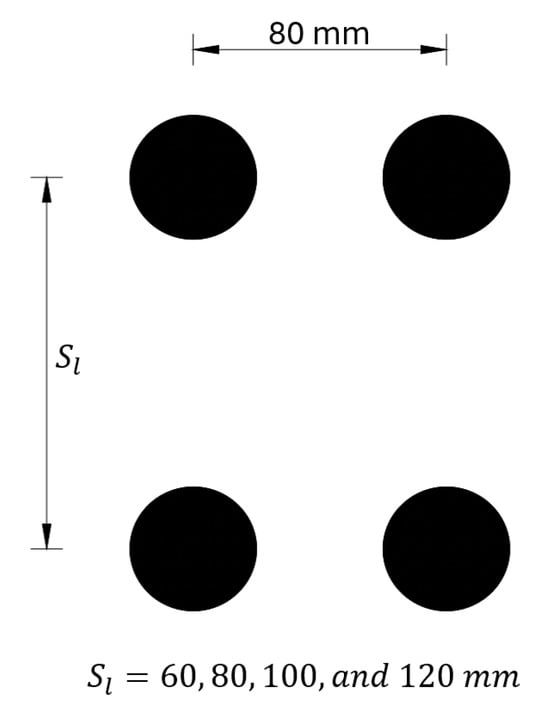
Figure 12.
Configuration of bolts.

Table 12.
Ultimate shear load and failure modes for different bolt spacings.
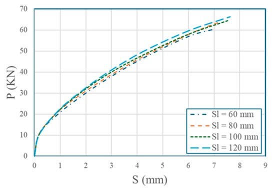
Figure 13.
Effect of the longitudinal spacing between bolts on P-S curves.
Although the number of bolts remains fixed in this parametric push-out study, in practical FRP–concrete hybrid beam designs, smaller longitudinal spacing would allow for a greater number of bolts over a fixed beam length, potentially increasing the total shear resistance, and thus the degree of shear connection η. The degree of shear connection (η), defined as the ratio of the total shear capacity provided by the bolts to the shear force required for full composite action (Vfull), was evaluated to clarify how longitudinal bolt spacing influences composite performance. The shear force for full composite action, Vfull = 1473.9 kN, was established as the minimum of the concrete compressive capacity and the tensile capacity of the GFRP profile (per Table 1 and Table 2) for the cross-section shown in Figure 1a, using ANSI/AISC 360-16 [59] adapted for FRP properties. For beams of 3.0 m and 1.2 m lengths, each with bolts arranged in two longitudinal rows, the total number of bolts was computed as N = 2 × ⌊L/s], where L represents the beam length in millimeters and s represents the longitudinal spacing. The total shear capacity and corresponding η were determined using the ultimate shear loads from Table 12 for each spacing configuration, as presented in Table 13. Configurations with smaller spacings yield higher η due to an increased number of bolts, though the efficiency of each individual bolt decreases due to bolt interaction. Conversely, larger spacings improve per-bolt shear capacity but reduce η due to fewer bolts. For the 3.0 m beam, η exceeds 1 across all spacings, indicating sufficient shear capacity to achieve full composite action. In contrast, for the 1.2 m beam, the reduced length results in fewer bolts, with η falling below 1 at the largest spacing, signifying partial composite action. The transition to partial composite action at larger spacings underscores the critical need to optimize bolt spacing to balance shear capacity and composite efficiency in FRP–concrete hybrid systems.

Table 13.
Degree of shear connection for longitudinal bolt spacings.
3.5. Effect of the Shear Connector Embedment Length
GFRP bolts (20 mm diameter) were tested with embedment lengths of 40 mm (he/d = 2.0), 50 mm (he/d = 2.5), 60 mm (he/d = 3.0), and 70 mm (he/d = 3.5) in a 2 × 2 configuration with 120 mm longitudinal row spacing, 80 mm horizontal spacing, and 57.8 MPa concrete. Results are in Table 14 and Figure 14. Higher he/d ratios increased shear capacity (33.59% from 2.0 to 3.5), shifting failure from pry-out to bolt shank shear at he/d ≥ 3.0, confirming [26]’s findings. P-S curves showed earlier load drops for lower he/d due to pry-out failure in the 2 × 2 configuration. Figure 15 illustrates the failure patterns of the concrete block in each case. For embedment lengths of 40 mm and 50 mm, tensile cracks are concentrated around the upper two bolts, while for embedment lengths of 60 mm and 70 mm, no visible cracks are observed. For shorter embedment lengths (40–50 mm), failure occurred by bolt extraction due to insufficient anchorage, due to the small size of the concrete cone and the short bolt embedment depth, while longer lengths (60–70 mm) led to bolt shank shear, as the anchorage was sufficient to transfer higher loads to the bolt itself.

Table 14.
Ultimate shear load and failure modes for different embedment lengths.
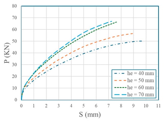
Figure 14.
Effect of embedment length on P-S curves.
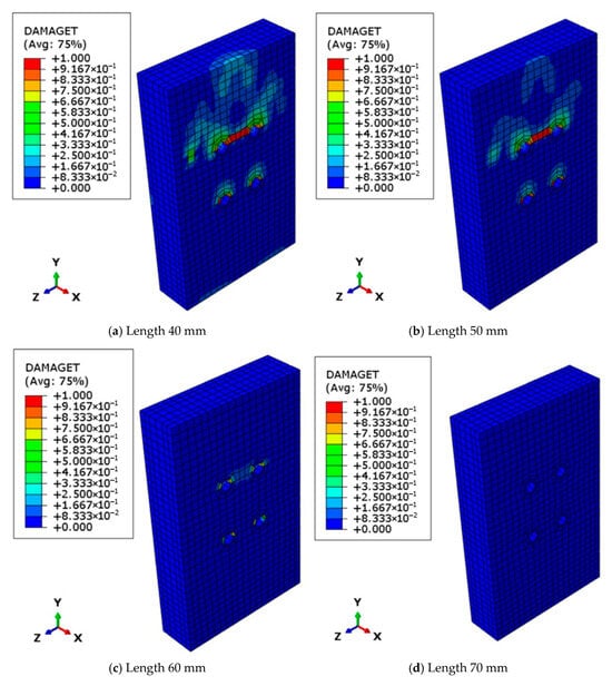
Figure 15.
Tensile damage in concrete for models with different embedment lengths.
3.6. Effect of the Concrete Compressive Strength
GFRP bolts with 20 mm diameter and 60 mm embedment length were tested with concrete compressive strengths of 30 MPa, 40 MPa, 57.8 MPa, and 70 MPa in a 2 × 2 configuration with 120 mm longitudinal row spacing and 80 mm horizontal spacing. Results are in Table 15 and Figure 16. Shear capacity increased by 22.07% from 30 MPa to 70 MPa, reflecting enhanced concrete-bearing capacity. Higher concrete strengths shifted failure modes from concrete slab splitting to bolt shank shear.

Table 15.
Ultimate shear load and failure modes for different concrete strengths.
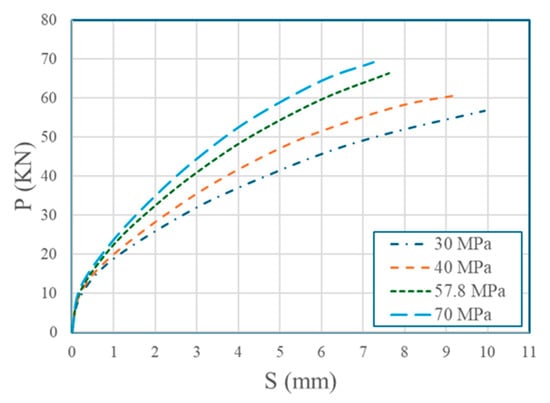
Figure 16.
Effect of the concrete compressive strength on P-S curves.
4. Discussion
The parametric study provides critical insights into the shear behavior of FRP shear connectors in FRP–concrete hybrid beams, addressing the research gaps identified in the introduction. The superior performance of CFRP bolts, demonstrating a shear capacity 26.50% higher than that of stainless-steel bolts (Table 9), aligns with their high longitudinal tensile strength (1600 MPa) and transverse shear strength (265 MPa). This underscores CFRP’s potential as a corrosion-resistant alternative to stainless steel, particularly in aggressive environments. AFRP bolts outperformed GFRP by 19.30%, indicating that material selection significantly influences shear performance.
GFRP bolts failed by shear failure of bolt shanks, while stainless steel, AFRP, and CFRP bolts failed by GFRP flange bearing failure. Due to the larger shear strength of stainless steel, AFRP, and CFRP bolts, their shear resistance was greater than the compressive strength of the GFRP flange. Additionally, their elastic modulus was higher than that of the GFRP profile, and thus, the bolt hole deformed under compression, resulting in failure at the GFRP profile. Therefore, GFRP bolts are suggested on account of full utilization of the strength of bolts with a minor effect on the capacity of specimens, especially since the ultimate shear capacity of GFRP bolts was only 2.4% lower than that of stainless-steel bolts.
Bolt diameter significantly impacts shear capacity, with a 90.60% increase from a GFRP bolt with a diameter of 16 mm to 30 mm (Table 10), driven by increased cross-sectional area. However, larger diameters (24 mm and 30 mm) shifted failure from bolt shank to concrete slab splitting due to exceeding the concrete’s bearing capacity, highlighting the need to balance bolt size with concrete strength. The shear stiffness of the GFRP bolt with a diameter of 30 mm was 82.32% higher than that of 16 mm. Therefore, a large diameter bolt appeared to be a preferable and advantageous option for hybrid beams.
The average per-bolt shear capacity decreased by 15.00% as the number of bolts increased from the 1 × 1 to the 3 × 2 configuration (Table 11). The cause of this effect is attributed to the arrangement of bolt shear connectors in groups, which results in non-uniform force distribution among the bolts. This reduction is attributed to the multi-bolt effect, where non-uniform load distribution causes the upper bolts to sustain higher forces and fail first, limiting the ability of the remaining bolts to effectively carry the shear load configurations (1 × 1, 2 × 1, and 2 × 2), predominantly failing by shear failure of the GFRP bolt shanks, but the 3 × 2 configuration exhibited concrete slab splitting due to it exceeding the concrete’s bearing capacity.
Longitudinal spacing increased per-bolt shear capacity by 9.48% from 60 mm (3d) to 120 mm (6d) (Table 12) by reducing bolt interaction and improving load distribution, consistently resulting in bolt shank shear failure. However, in beams, larger spacings reduced the total number of bolts, decreasing overall shear resistance and the degree of shear connection (η) (Table 13). The results suggest that a longitudinal spacing of 6d (120 mm) optimizes per-bolt shear capacity by minimizing bolt interaction, making it suitable for applications prioritizing individual bolt efficiency. However, in practical FRP–concrete hybrid beam designs, smaller spacings (e.g., 3d or 4d) may be preferred to maximize the number of bolts and achieve full composite action, as evidenced by higher η values. Designers must balance per-bolt capacity with the total shear resistance required, considering beam length and loading conditions to avoid partial composite action that could reduce structural efficiency.
Embedment length had a significant influence on the failure modes of GFRP shear connectors in FRP–concrete hybrid beam models. At shorter embedment lengths of 40 mm and 50 mm (he/d < 3), failure was governed by bolt extraction (pry-out), which is attributed to insufficient anchorage between the GFRP bolts and the surrounding concrete. In contrast, at embedment lengths of 60 mm and 70 mm (he/d ≥ 3.0), the failure mode transitioned to bolt shank shear, indicating improved anchorage. Notably, the shear capacity increased by 33.59% when the embedment length was increased from 40 mm to 70 mm (Table 14), highlighting the critical role of sufficient embedment in enhancing shear resistance. Based on these findings, a minimum he/d ratio of 3.0 is recommended to prevent pry-out failure and ensure effective load transfer.
Higher concrete compressive strengths, ranging from 30 MPa to 70 MPa, increased the shear capacity of GFRP bolts by 22.07% (Table 15). This enhancement shifted the failure mode from concrete slab splitting at 30 MPa and 40 MPa to bolt shank shear at 57.8 MPa and 70 MPa, reflecting improved concrete-bearing capacity.
5. Conclusions
This study presented a comprehensive finite element (FE) investigation and parametric analysis of GFRP, CFRP, AFRP, and stainless-steel bolted shear connectors in FRP–concrete hybrid beams, addressing critical gaps in current understanding of shear transfer mechanisms. The validated FE model, developed in Abaqus and calibrated against experimental push-out tests, accurately reproduced load–slip curves and failure modes, with prediction errors within 6% in both elastic and plastic regimes. The model proved capable of capturing different failure mechanisms, including bolt shank shear, flange bearing failure, concrete splitting, and pry-out, thus enabling a reliable platform for extended parametric exploration. The key findings of this study can be summarized as follows:
- 1.
- CFRP bolts demonstrated the highest shear capacity, exceeding stainless-steel bolts by 26.50%, followed by AFRP and GFRP bolts. GFRP bolts failed predominantly by bolt shank shear, fully utilizing their tensile capacity, whereas CFRP, AFRP, and stainless-steel bolts failed by GFRP flange bearing. This finding highlights CFRP’s potential as a superior corrosion-resistant connector material for long-term durability in aggressive environments.
- 2.
- Shear capacity increased by up to 90.60% when the diameter was raised from 16 mm to 30 mm. However, larger diameters shifted the governing failure mode from bolt shank shear to concrete slab splitting, underscoring the need to balance bolt size with available concrete-bearing strength to prevent brittle concrete failures.
- 3.
- Increasing the number of bolts reduced the average per-bolt shear capacity by up to 15.00% due to non-uniform force distribution in multi-bolt arrangements. This finding indicates that excessive grouping of bolts may result in premature failure of the most highly loaded connectors, limiting overall efficiency.
- 4.
- Increasing longitudinal spacing from 3d to 6d improved per-bolt shear capacity by 9.48% by reducing bolt interaction. However, larger spacings reduce the total number of bolts over a given beam length and may result in partial composite action. Optimized spacing must, therefore, consider both per-bolt efficiency and the total shear demand of the system.
- 5.
- Higher embedment ratios (he/d ≥ 3.0) increased shear capacity by 33.59% and shifted failure from pry-out to bolt shank shear, demonstrating the importance of adequate anchorage depth for efficient load transfer and prevention of brittle failure modes.
- 6.
- Raising concrete strength from 30 MPa to 70 MPa enhanced shear capacity by 22.07% and shifted failure from concrete splitting to bolt shank shear, indicating improved concrete confinement and load-carrying capability.
It should be noted that the present results were obtained for a specific wall thickness of the pultruded GFRP profile; hence, the conclusions drawn are directly applicable only to this configuration. The wall thickness can influence the bearing stress distribution around bolt holes, stiffness, and failure mode. Thicker profiles typically enhance local bearing strength, whereas thinner ones are more prone to flange deformation and localized crushing. Future studies are recommended to include a parametric evaluation of GFRP thickness to broaden the applicability of the findings.
Author Contributions
Conceptualization, H.F.S. and A.E.-Z.; data curation, A.Z.; formal analysis, A.Z.; methodology, A.Z.; resources, A.E.-Z.; software, A.Z.; supervision, H.F.S.; validation, A.Z.; visualization, H.F.S. and A.E.-Z.; writing—original draft, A.Z.; writing—review and editing, H.F.S. and A.E.-Z. All authors have read and agreed to the published version of the manuscript.
Funding
This research received no external funding.
Data Availability Statement
The original contributions presented in this study are included in the article. Further inquiries can be directed to the corresponding author.
Conflicts of Interest
The authors declare no conflicts of interest.
References
- Hollaway, L.C. A review of the present and future utilisation of FRP composites in the civil infrastructure with reference to their important in-service properties. Constr. Build. Mater. 2010, 24, 2419–2445. [Google Scholar] [CrossRef]
- Zou, X.; Lin, H.; Feng, P.; Bao, Y.; Wang, J. A review on FRP-concrete hybrid sections for bridge applications. Compos. Struct. 2021, 262, 113336. [Google Scholar] [CrossRef]
- Rajchel, M.; Siwowski, T. Hybrid Bridge structures made of FRP composite and concrete. Civ. Environ. Eng. Rep. 2017, 26, 161–169. [Google Scholar] [CrossRef][Green Version]
- Hou, B.; Li, X.; Ma, X.; Du, C.; Zhang, D.; Zheng, M.; Xu, W.; Lu, D.; Ma, F. The cost of corrosion in China. npj Mater. Degrad. 2017, 1, 4. [Google Scholar] [CrossRef]
- Nordin, H.; Täljsten, B. Testing of hybrid FRP composite beams in bending. Compos. Part B Eng. 2004, 35, 27–33. [Google Scholar] [CrossRef]
- Zou, X.; Feng, P.; Wang, J. Bolted shear connection of FRP-concrete hybrid beams. J. Compos. Constr. 2018, 22, 04018012. [Google Scholar] [CrossRef]
- El-Zohairy, A.; Salim, H.; Shaaban, H. Experimental investigation on fatigue behavior of composite beams with different studs arrangements. Structures 2022, 35, 146–159. [Google Scholar] [CrossRef]
- Elshihy, A.; Fawzy, H.; Hassan, H.; Elbelbisi, A. Strengthening of pre-stressed steel-concrete composite beams using carbon fiber tendons (parametric study). In Proceedings of the EuroSciCon Conference on Nanotechnology & Smart Materials, Amsterdam, The Netherlands, 4–6 October 2018. [Google Scholar] [CrossRef]
- Liu, T.; Feng, P.; Lu, X.; Yang, J.Q.; Wu, Y. Flexural behavior of novel hybrid multicell GFRP-concrete beam. Compos. Struct. 2020, 250, 112606. [Google Scholar] [CrossRef]
- Van Erp, G.; Cattell, C.; Heldt, T. Fibre composite structures in Australia’s civil engineering market: An anatomy of innovation. Prog. Struct. Eng. Mater. 2005, 7, 150–160. [Google Scholar] [CrossRef]
- Ulloa, F.V.; Medlock, R.D.; Ziehl, P.H.; Fowler, T.J. Hybrid bridges in Texas. Concr. Int. 2004, 26, 38–43. [Google Scholar]
- Gutiérrez, E.; Primi, S.; Mieres, J.M.; Calvo, I. Structural testing of a vehicular carbon fiber bridge: Quasi-static and short-term behavior. J. Bridge Eng. 2008, 13, 271–281. [Google Scholar] [CrossRef]
- Mieres, J.M.; Calvo, I.; Miravete, A.; Gutiérrez, E.; Shahidi, E.; López, C.; Cuartero, J.; Comino, P.; de Villoria, R.G. Description of a traffic bridge of the Cantabrian SpeedWay made of composite materials. Mater. Construcción 2006, 56, 81–86. [Google Scholar] [CrossRef][Green Version]
- Siwowski, T.; Rajchel, M.; Kaleta, D. Development, testing and construction of the hybrid FRP composite–concrete road bridge. In IABSE Symposium Report; International Association for Bridge and Structural Engineering: Zurich, Switzerland, 2017; Volume 109, pp. 1816–1823. [Google Scholar][Green Version]
- Siwowski, T.; Rajchel, M. Dynamic performance of a vehicular bridge with lightweight FRP composite structural elements. In MATEC Web of Conferences; EDP Sciences: Les Ulis, France, 2019; Volume 285, p. 00016. [Google Scholar][Green Version]
- Siwowski, T.; Rajchel, M.; Kulpa, M. Design and field evaluation of a hybrid FRP composite–Lightweight concrete road bridge. Compos. Struct. 2019, 230, 111504. [Google Scholar] [CrossRef]
- Pardeshi, R.T.; Patil, Y.D. Review of various shear connectors in composite structures. Adv. Steel Constr. 2021, 17, 394–402. [Google Scholar]
- Lin, J.P.; Qiao, N.; Zhang, L.; Tang, J.; Zhou, L.; Huo, J.; Wang, G. Study on the mechanical properties of hybrid bonding shear connections with shear studs and epoxy mortar layer. Structures 2024, 70, 107642. [Google Scholar] [CrossRef]
- Zhou, H.; Zhang, Z.; Wu, C.; Wang, H.; Yang, J.; Zou, Y. Shear performance of high-strength bolt-epoxy bonding composite connector in steel-concrete composite structure. Structures 2024, 61, 106085. [Google Scholar] [CrossRef]
- Zou, X.; Feng, P.; Wang, J. Perforated FRP ribs for shear connecting of FRP-concrete hybrid beams/decks. Compos. Struct. 2016, 152, 267–276. [Google Scholar] [CrossRef]
- Kopp, M.; Wolters, K.; Claßen, M.; Hegger, J.; Gündel, M.; Gallwoszus, J.; Heinemeyer, S.; Feldmann, M. Composite dowels as shear connectors for composite beams–Background to the design concept for static loading. J. Constr. Steel Res. 2018, 147, 488–503. [Google Scholar] [CrossRef]
- Seidl, G.; Petzek, E.; Băncilă, R. Composite dowels in bridges-efficient solution. Adv. Mater. Res. 2013, 814, 193–206. [Google Scholar] [CrossRef]
- Altoé, J.V.; Faria, C.S.; Petrauski, M.C.; Pereira, C.L.; Paes, J.L.; Veríssimo, G.D. Composite dowels shear connectors for steel-concrete composite beams: A review. Rev. IBRACON De Estrut. E Mater. 2025, 18, e18204. [Google Scholar] [CrossRef]
- Ollgaard, J.G.; Slutter, R.G.; Fisher, J.W. Shear strength of stud connectors in lightweight and normal-weight concrete. Eng. J. 1971, 8, 55–64. [Google Scholar] [CrossRef]
- Lee, P.G.; Shim, C.S.; Chang, S.P. Static and fatigue behavior of large stud shear connectors for steel–concrete composite bridges. J. Constr. Steel Res. 2005, 61, 1270–1285. [Google Scholar] [CrossRef]
- Liu, Y.; Zhang, Q.; Bao, Y.; Bu, Y. Static and fatigue push-out tests of short headed shear studs embedded in Engineered Cementitious Composites (ECC). Eng. Struct. 2019, 182, 29–38. [Google Scholar] [CrossRef]
- Xue, W.; Yan, D.; Zhang, S. Push-out behavior of GFRP bolts shear connectors in FRP-concrete hybrid beam. Eng. Struct. 2023, 294, 116758. [Google Scholar] [CrossRef]
- Nguyen, H.; Mutsuyoshi, H.; Zatar, W. Push-out tests for shear connections between UHPFRC slabs and FRP girder. Compos. Struct. 2014, 118, 528–547. [Google Scholar] [CrossRef]
- D’Antino, T.; Bertolli, V.; Pisani, M.A.; Poggi, C. Tensile and interlaminar shear behavior of thermoset and thermoplastic GFRP bars exposed to alkaline environment. J. Build. Eng. 2023, 72, 106581. [Google Scholar] [CrossRef]
- Deskovic, N.; Triantafillou, T.C.; Meier, U. Innovative Design of FRP Combined with Concrete: Short-Term Behavior. J. Struct. Eng. 1995, 121, 1069–1078. [Google Scholar] [CrossRef]
- Huang, H.; Li, A.; Chen, L.; Zeng, C.; Zhu, M. Push-out tests for shear connectors in GFRP-concrete composite bridge deck slabs. J. Adv. Concr. Technol. 2018, 16, 368–381. [Google Scholar] [CrossRef]
- Cho, J.R.; Park, S.Y.; Cho, K.; Kim, S.T.; Kim, B.S. Pull-out test and discrete spring model of fibre-reinforced polymer perfobond rib shear connector. Can. J. Civ. Eng. 2012, 39, 1311–1320. [Google Scholar] [CrossRef]
- Xiong, Z.; Liu, Y.; Zuo, Y.; Xin, H. Experimental evaluation of shear behavior of pultruded GFRP perforated connectors embedded in concrete. Compos. Struct. 2019, 222, 110938. [Google Scholar] [CrossRef]
- Correia, J.R.; Branco, F.A.; Ferreira, J. GFRP–concrete hybrid cross-sections for floors of buildings. Eng. Struct. 2009, 31, 1331–1343. [Google Scholar] [CrossRef]
- Correia, J.R.; Branco, F.A.; Ferreira, J.G. Flexural behaviour of GFRP–concrete hybrid beams with interconnection slip. Compos. Struct. 2007, 77, 66–78. [Google Scholar] [CrossRef]
- Zou, X.; Feng, P.; Wang, J.; Wu, Y.; Feng, Y. FRP stay-in-place form and shear key connection for FRP-concrete hybrid beams/decks. Compos. Struct. 2018, 192, 489–499. [Google Scholar] [CrossRef]
- Etim, O.; Gand, A.K.; Saidani, M.; Fom, P.; Ganjian, E.; Okon, E. Shear characterisation of pultruded superstructural FRP-concrete push-outs. Structures 2020, 23, 254–266. [Google Scholar] [CrossRef]
- Fam, A.; Skutezky, T. Composite T-beams using reduced-scale rectangular FRP tubes and concrete slabs. J. Compos. Constr. 2006, 10, 172–181. [Google Scholar] [CrossRef]
- Xue, W.; Ding, M.; Wang, H.; Luo, Z. Static behavior and theoretical model of stud shear connectors. J. Bridge Eng. 2008, 13, 623–634. [Google Scholar] [CrossRef]
- Oehlers, D.J.; Coughlan, C.G. The shear stiffness of stud shear connections in composite beams. J. Constr. Steel Res. 1986, 6, 273–284. [Google Scholar] [CrossRef]
- GB/T 50081-2019; Standard for Test Methods of Concrete Physical and Mechanical Properties. China Architecture & Building Press: Beijing, China, 2019.
- Michał, S.; Andrzej, W. Calibration of the CDP model parameters in Abaqus. In Proceedings of the World Congress on Advances in Structural Engineering and Mechanics (ASEM15), Incheon, Republic of Korea, 25 August 2015. [Google Scholar]
- Ali, L.; Nawaz, A.; Bai, Y.; Raza, A.; Anwar, M.K.; Raheel Shah, S.A.; Raza, S.S. Numerical Simulations of GFRP—Reinforced Columns Having Polypropylene and Polyvinyl Alcohol Fibers. Complexity 2020, 2020, 8841795. [Google Scholar] [CrossRef]
- Arrayago, I.; Real, E.; Gardner, L. Description of stress–strain curves for stainless steel alloys. Mater. Des. 2015, 87, 540–552. [Google Scholar] [CrossRef]
- Iteka, R.; Adibi, P. Material Characterization of 316L. ISRN LUTFD2/TFHF-19/5234-SE (1-71). Master’s Dissertation, Lund University, Lund, Sweden, 2019. [Google Scholar]
- Raza, A.; Khan, Q.U.; Ahmad, A. Numerical Investigation of Load—Carrying Capacity of GFRP—Reinforced Rectangular Concrete Members Using CDP Model in ABAQUS. Adv. Civ. Eng. 2019, 2019, 1745341. [Google Scholar] [CrossRef]
- Yuan, J. Flexural Behaviour of Composite Beams Reinforced with GFRP I-Section. Ph.D. Thesis, University of Wollongong, Wollongong, Australia, 2017. [Google Scholar]
- Yuan, J.S.; Hadi, M.N. Friction coefficient between FRP pultruded profiles and concrete. Mater. Struct. 2018, 51, 120. [Google Scholar] [CrossRef]
- Hosseinpour, M.; Zeynalian, M.; Daei, M.; Ataei, A. Numerical study on behavior of bolted shear connector used in composite cold-formed steel beams. Thin-Walled Struct. 2022, 177, 109377. [Google Scholar] [CrossRef]
- Mottram, J. Friction and load transfer in bolted joints of pultruded fibre reinforced polymer section. FRP Compos. Civ. Eng. CICE 2004 2004, 15, 845–850. [Google Scholar]
- Sallam, H.E.; Al-Tersawy, S.H.; Sayed, S.A. Effect of Fiber Orientation on Friction and Wear Resistance of Polymeric Matrix and Metal Matrix Composites. In Proceedings of the 9th Arab International Conference on Polymer Science & Technology, Hurghada, Egypt, 14–18 September 2007. [Google Scholar]
- Yang, Z.; Lu, C.; Yuan, S.; Ge, H. Effect of Mechanical Interlocking Damage on Bond Durability of Ribbed and Sand-Coated GFRP Bars Embedded in Concrete Under Chloride Dry–Wet Exposure. Polymers 2025, 17, 733. [Google Scholar] [CrossRef]
- Ali, M.I.; Allawi, A.A.; El-Zohairy, A. Flexural behavior of pultruded GFRP–concrete composite beams strengthened with GFRP stiffeners. Fibers 2024, 12, 7. [Google Scholar] [CrossRef]
- Nguyen, H.T.; Kim, S.E. Finite element modeling of push-out tests for large stud shear connectors. J. Constr. Steel Res. 2009, 65, 1909–1920. [Google Scholar] [CrossRef]
- Aniskevich, K.; Aniskevich, A.; Arnautov, A.; Jansons, J. Mechanical properties of pultruded glass fiber-reinforced plastic after moistening. Compos. Struct. 2012, 94, 2914–2919. [Google Scholar] [CrossRef]
- Kaw, A.K. Mechanics of Composite Materials; CRC Press: Boca Raton, FL, USA, 2005. [Google Scholar]
- Barbero, E.J. Introduction to Composite Materials Design; CRC Press: Boca Raton, FL, USA, 2010. [Google Scholar]
- Daniel, I.M.; Ishai, O.; Daniel, I.M.; Daniel, I. Engineering Mechanics of Composite Materials; Oxford University Press: New York, NY, USA, 1994. [Google Scholar]
- ANSI/AISC 360-16; Specification for Structural Steel Buildings. American Institute of Steel Construction (AISC): Chicago, IL, USA, 2016.
Disclaimer/Publisher’s Note: The statements, opinions and data contained in all publications are solely those of the individual author(s) and contributor(s) and not of MDPI and/or the editor(s). MDPI and/or the editor(s) disclaim responsibility for any injury to people or property resulting from any ideas, methods, instructions or products referred to in the content. |
© 2025 by the authors. Licensee MDPI, Basel, Switzerland. This article is an open access article distributed under the terms and conditions of the Creative Commons Attribution (CC BY) license (https://creativecommons.org/licenses/by/4.0/).