Abstract
In the present experiment, the abrasive water jet machining parameters, such as water pressure, standoff distance, and traverse speed, are selected to study the effect of each parameter on the kerf taper angle and surface roughness during the machining of glass, jute, and carbon hybrid composite. The other machining parameters are kept constant. For each parameter, three levels are fixed on the basis of previous literature reviews. The Response Surface Methodology is used to design the required number of experiments and to optimize the machining parameters to obtain the minimum kerf taper angle and surface roughness. The levels selected for water pressure are 150, 220, and 250 MPa; traverse speeds are 20, 40, and 60 mm/min; and, similarly, stand-off distances are 2, 5, and 8 mm. Experimental results confirm that the parameter inversely affects both kerf angle and surface roughness. On the other hand, parameters traverse speed and stand-off distance, directly affecting both outputs. According to RSM optimization, to obtain the minimum kerf taper angle and surface roughness, we should fix the pressure at a higher level and other parameters at a lower level. For the considered range, the obtained minimum kerf angle and roughness values are 1.4982 radians and 2.0920 μm.
1. Introduction
The rapid advancement in materials science and manufacturing has fostered the development and application of hybrid fiber-reinforced polymer (FRP) composites have gained significant attention across diverse sectors such as aerospace, automotive, defense, and biomedical industries owing to their exceptional specific strength, high stiffness-to-weight ratio, excellent corrosion resistance, and design flexibility [,,]. These advanced materials integrate multiple types of reinforcing fibers such as glass, aramid, jute, and carbon to synergistically combine their individual advantages and overcome the limitations of single-fiber composites. in a single matrix to achieve a balance of mechanical, thermal, and environmental properties that are difficult to realize with single-fiber systems [,,]. However, machining hybrid composites poses challenges due to their non-homogeneous and anisotropic structure, which can lead to defects such as delamination, fiber pull-out, matrix burning, and poor dimensional accuracy during conventional machining processes [,,]. To address these issues, Abrasive Water Jet Machining (AWJM) has emerged as a promising non-traditional machining technique. AWJM uses a high-pressure jet of water mixed with abrasive particles to cut through composite materials without causing thermal damage, residual stress, or tool wear [,,].
Key quality indicators in AWJM include kerf taper angle (KT) and surface roughness (Ra), both of which significantly affect the dimensional accuracy and surface integrity of machined components [,]. Kerf taper is the angular deviation between the top and bottom of the cut, with a smaller value indicating higher cut quality []. Surface roughness represents the texture of the cut surface and plays a critical role in determining post-processing requirements and mechanical performance []. Several studies have highlighted the critical influence of process parameters—water pressure (P), stand-off distance (SOD), traverse speed (TS), and abrasive flow rate (AFR)—on AWJM outcomes. High water pressure enhances cutting efficiency by increasing the velocity of abrasive particles, resulting in a reduced kerf taper and improved surface finish [,]. Conversely, increased stand-off distance tends to decrease jet energy concentration at the target, increasing kerf taper and surface roughness [,]. Traverse speed affects the time of jet interaction with the material: higher speeds may result in insufficient material erosion, leading to poor cut quality [,].
To optimize the AWJM process and minimize kerf taper and surface roughness, advanced statistical and soft computing techniques such as Response Surface Methodology (RSM), Taguchi method, Genetic Algorithms (GA), and Artificial Neural Networks (ANN) have been widely used [,]. Among these, RSM is particularly effective due to its ability to model nonlinear relationships and predict optimal parameter combinations with fewer experimental trials [,]. Recent investigations have applied RSM to optimize AWJM for various composites. Ramesh et al. [,] studied hybrid natural fiber composites and found that higher pressure with low SOD yields optimal kerf quality. Bhattacharya et al. [] examined CFRP composites and optimized parameters to reduce kerf irregularity. Another study by Uthayakumar et al. [] confirmed that pressure and abrasive flow rate were the most significant factors affecting Ra and KT in epoxy-glass composites. In light of these developments, this study investigates the AWJM of a glass–aramid–jute reinforced epoxy composite, focusing on the optimization of kerf taper angle and surface roughness using RSM. The primary objective is to model and identify the best combination of water pressure, stand-off distance, and traverse speed that yields the minimum kerf taper and surface roughness, ensuring optimal machining quality for hybrid composites.
Although several studies have investigated AWJM of composites such as GFRP, CFRP, and natural fiber-reinforced polymers, most have concentrated on single-fiber systems or traditional FRPs, typically analyzing parameters such as water pressure in the range of 150–350 MPa, traverse speed between 20 and 200 mm/min, 1–10 mm of stand-off distance, and abrasive flow rate of 0.2–0.4 kg/min, with the aim of improving either kerf quality or surface finish. While these works provide useful insights, they often neglect the complex behavior of hybrid composites where multiple fibers of different mechanical and physical properties are combined in a single matrix. The heterogeneous and anisotropic nature of such hybrid composites presents unique machining challenges that remain underexplored. The present study aims to bridge this research gap by investigating the machinability of glass–aramid–jute reinforced epoxy hybrid composites under varying process conditions. Specifically, the combined influence of water jet pressure, traverse speed, and stand-off distance on kerf taper angle and surface roughness is systematically analyzed. Furthermore, Response Surface Methodology (RSM) is employed to assess both the individual and interactive effects of these machining parameters and to optimize them concurrently for minimizing kerf taper and surface roughness. The findings of this study advance the current understanding of hybrid composite machining, providing valuable insights and practical guidelines for achieving superior dimensional accuracy and surface integrity in industrial applications involving advanced fiber-reinforced composites.
2. Methodology
2.1. Preparation of Hybrid Composite Specimen
The composite material was fabricated using the hand layup method, a conventional but highly effective technique for producing fiber-reinforced composites in controlled laboratory settings. The matrix used for the composite was Epoxy LY 556, procured from Huntsman Polymers, Mumbai, India. The corresponding hardener employed was HY 951. The reinforcement materials, including glass, aramid, and jute fibers with a fiber diameter of around 10–20 µm, were selected for their complementary mechanical and physical properties.
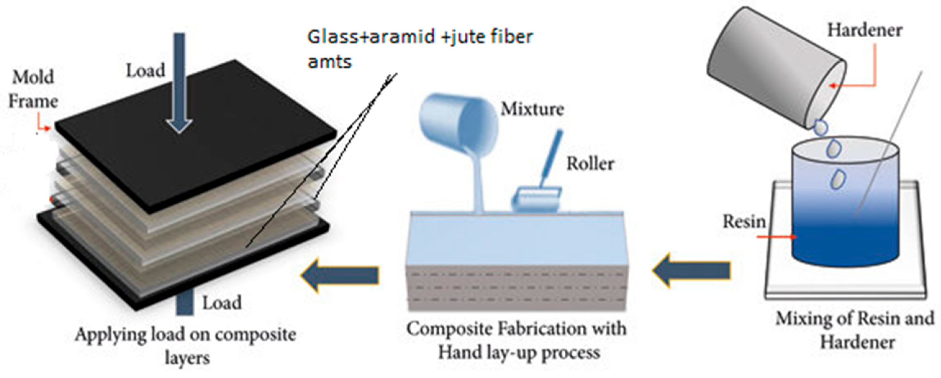
To begin the layup process, fiber mats were cut into appropriately sized layers. A releasing agent was applied to the steel mold plates to prevent the composite from bonding to the mold during curing. The stacking sequence was critical and followed a specific order: two layers of glass fiber, followed by two layers of aramid fiber, and finally two layers of jute fiber. The matrix and fibers were mixed in a weight ratio of 60:40, where epoxy accounted for 60% and the fiber reinforcements 40%. Each layer of fiber was impregnated with resin before being stacked []. The stacked assembly was covered with polythene sheets and compressed using a hydraulic hot press machine to eliminate voids and ensure uniform resin distribution. Curing was allowed for 48 h under pressure to achieve full cross-linking of the matrix.
After curing, the composite panel was trimmed along its edges to achieve uniformity and was sectioned into test specimens suitable for AWJM. The schematic representation of the hand layup method is illustrated in Figure 1. This figure shows the steps involved in creating the hybrid composite. Fiber mat cutting, epoxy and hardener mixing, glass, aramid, and jute layer stacking, releasing agent application, hydraulic press compression, and final curing are all demonstrated. It explains how void-free laminates and consistent resin distribution were accomplished prior to machining.
Figure 1.
Schematic representation of the hand layup method.
2.2. Abrasive Water Jet Machining
The samples were firmly fastened to a piece of cardboard using double-sided tape. The cutting procedure was executed utilizing a 5-axis water jet cutting machine (Omax Corp., Kent, WA, USA; model no. MAXIEM1515). The setup for machining is depicted in Figure 2. The Omax MAXIEM1515 five-axis cutting system is shown in this picture. It draws attention to the specimen fixture, focusing nozzle, mixing chamber where garnet abrasive is entrained, and high-pressure pump. This image demonstrates that the standoff distance was carefully managed and that the nozzle orientation was normal (90°) to the workpiece. Three input parameters were varied: standoff distance (SOD), traverse speed (TS), and Water pressure (P). For each of these parameters, three levels of adjustment were determined and mentioned in the later paragraphs.
Figure 2.
The machining setup.
To ensure precise machining results, the equipment configuration underwent thorough testing across several critical parameters before commencing the machining operation, despite the machine itself being subject to routine inspections and maintained in optimal condition. Evaluation procedures verified that both the nozzle and orifice remained free from any signs of wear or damage. Precision cutting required meticulous measurement and fine-tuning of the abrasive flow rate. Water pressure levels were assessed and calibrated as needed. The traverse speed for each operational stage was determined and adjusted to meet the specific requirements of the process. Special care was taken to verify and set accurate standoff distance parameters. The ratios for abrasive mixing were systematically monitored and modified to ensure effective blending with the water stream. Cutting depth was precisely calibrated and adapted to correspond with the characteristics of the test specimen. Upon confirmation and adjustment of all relevant parameters, preliminary tests were conducted to confirm the accuracy and quality of the machining on the specimen.
In this experiment, Abrasive Water Jet Machining (AWJM) was performed using almandine garnet as the abrasive medium. Almandine garnet, a commonly used and cost-effective abrasive, is valued for its angular particle morphology, high hardness, and sharp cutting edges. It belongs to the silicate mineral group and occurs in a wide range of colors, including red, orange, yellow, green, purple, brown, blue, black, pink, and colorless varieties. Among these, almandine is particularly preferred for industrial applications due to its characteristic deep red to reddish-brown hue and superior mechanical robustness. It is naturally found in certain igneous formations and metamorphic rocks such as gneiss and schist, as well as in placer deposits formed through sedimentary concentration of weathered minerals. Owing to its high hardness (7.5–8.0 on the Mohs scale) and stable chemical nature, almandine garnet demonstrates excellent cutting efficiency across a variety of materials, including metals, ceramics, and polymer composites. The abrasive is commercially available in different mesh sizes, typically ranging from fine (230 mesh) to coarse (50 mesh). In the present study, 80-mesh garnet was employed, as it is widely regarded as the optimal grade for achieving a balance between cutting efficiency and surface finish in water jet machining. Additionally, unlike certain synthetic abrasives, garnet is non-toxic and environmentally benign, thereby minimizing health and ecological risks. The machining trials were conducted at a constant water jet pressure of 200 MPa, with the jet impinging perpendicularly at a 90° angle to the specimen surface.
2.3. Selection of Machining Parameters and Their Levels
Water pressure (P), Standoff distance (SOD), and traverse speed (TS) are the selected input parameters. Table 1 shows the selected parameters with their levels. The selection was made based on the literature review [].
Table 1.
The considered Input parameters.
2.4. Measurement of Kerf Taper Angle and Surface Roughness
The kerf taper angle (θ°) was determined by measuring the top and bottom kerf widths and substituting these values into Equation (1) [,], where θ° denotes the kerf taper angle, Tw represents the top kerf width, Bw corresponds to the bottom kerf width, and t signifies the material thickness. The top and bottom kerf widths were precisely measured using a reflected light industrial microscope (OLYMPUS BX51M) integrated with the Olympus Stream Essentials image analysis software. Measurements were recorded at three distinct locations along each cut to ensure accuracy and repeatability. The kerf taper angle was subsequently computed, and the mean value was considered for analysis. The schematic representation of the kerf angle measurement at the top and bottom positions is shown in Figure 3A,B
where: Tw and Bw = top and bottom kerf width, t = material thickness.
Figure 3.
(A) KT measurement at top. (B) KT measurement at the bottom.
Surface roughness was measured using the Taylor Hobson Surtronic surface instrument at 3 different regions. The final Ra values were determined by averaging two readings taken at various locations.
2.5. Design of Experiments (DOE)
To systematically investigate the influence of machining parameters on kerf taper angle and surface roughness, a structured design of experiments (DOE) approach was adopted. DOE ensures efficient experimentation with reduced trials while maintaining statistical reliability. In this study, both the Taguchi method and Response Surface Methodology (RSM) were considered to evaluate and optimize the process parameters. Response Surface Methodology (RSM) with Box–Behnken Design was adopted to obtain a more detailed model and capture the interactive effects of parameters. Among various RSM designs, the Box–Behnken design (BBD) was selected due to its efficiency and suitability for three-factor studies, avoiding extreme corner points that could lead to experimental infeasibility or damage to specimens. The three selected input parameters and their levels are listed in Table 2.
Table 2.
Experimental results.
3. Results and Discussion
Results obtained from the experimentation are summarized in Table 2.
3.1. Analysis of Kerf Taper Angle (KT)
3.1.1. Regression Equation for Kerf Angle
The regression equation for kerf taper angle is shown in Equation (2). This equation reveals that the parameter P has a negative effect on the kerf angle. Additionally, it confirms that as the pressure increases, the kerf angle decreases. The two other parameters positively impacting the kerf taper angle are the SOD and TS. It also confirms that the combined effect of all parameters is having a positive impact.
KA = 1.6033 − 0.000513 P + 0.01112 SOD + 0.00019 TS + 0.000066 P × SOD + 0.000001 P × TS
+ 0.000064 SOD × TS
+ 0.000064 SOD × TS
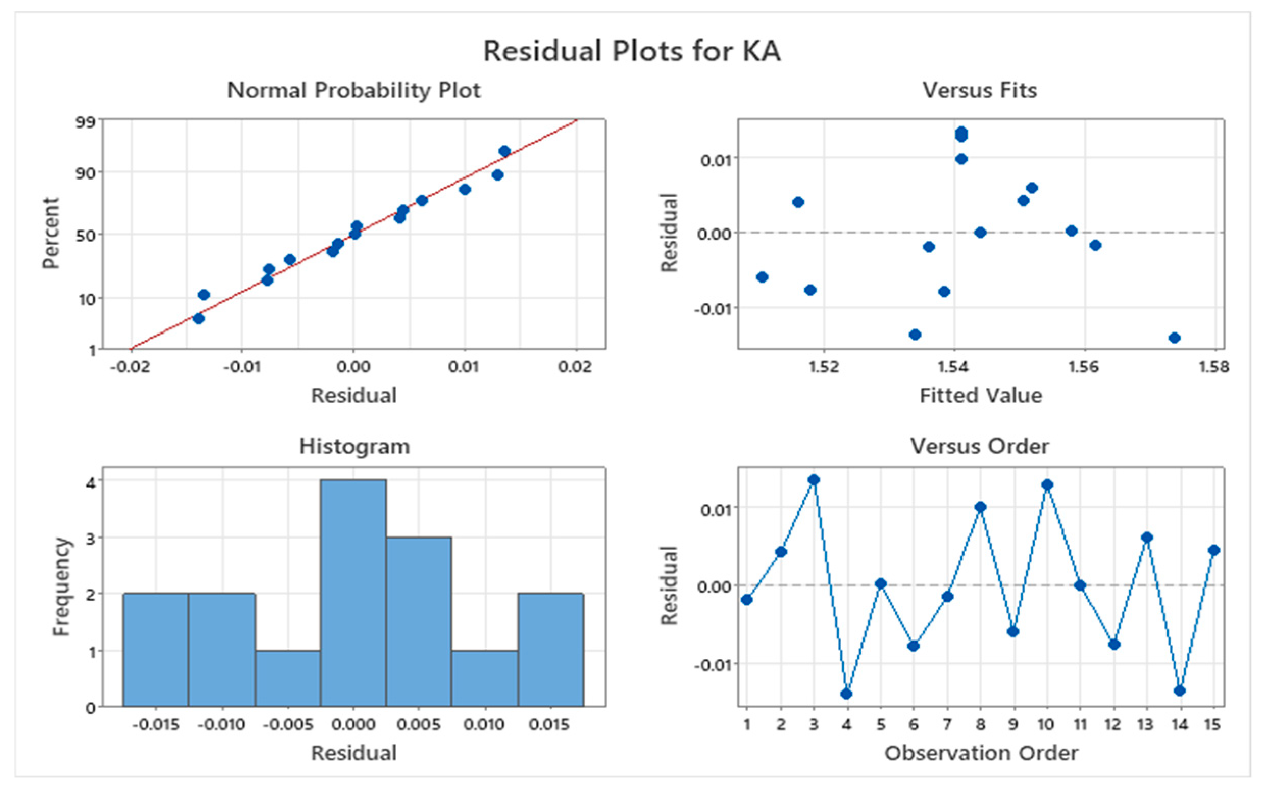
The residual plot, which shows the difference between an observed value and the value predicted by the regression model for the present experimentation, is presented in Figure 4. The normal probability plot exhibits the normal distribution of the collected data by showing the values scattered close to the normal distribution line. Hence, the collected data can be utilized for further analysis. Other graphs also show the proper distribution of the data and confirm the proper data collection method.
Figure 4.
Residual and other plots for Kerf Angle.
Figure 5 displays the main effect plot for the KT. The data confirms that the parameter SOD has a highly significant effect on SURFACE ROUGHNESS. The next most influential parameter is TS, while the least impactful parameter is P. Therefore, it is advisable to avoid varying the levels of the SOD parameter compared to the other two parameters, as even a small change in SOD can lead to a substantial variation in SURFACE ROUGHNESS.
Figure 5.
Main effect plot for Kerf Angle.
3.1.2. ANOVA for Kerf Angle (KT)
The ANOVA table for KT is presented in the Table 3. The p-value indicates that the parameters SOD and TS significantly affect SURFACE ROUGHNESS. Among these, SOD has a greater significance. In contrast, the parameter P does not have a significant effect on kerf taper. When considering combined effects, the interaction between P and SOD has a greater impact on the output parameter.
Table 3.
ANOVA for Kerf Angle.
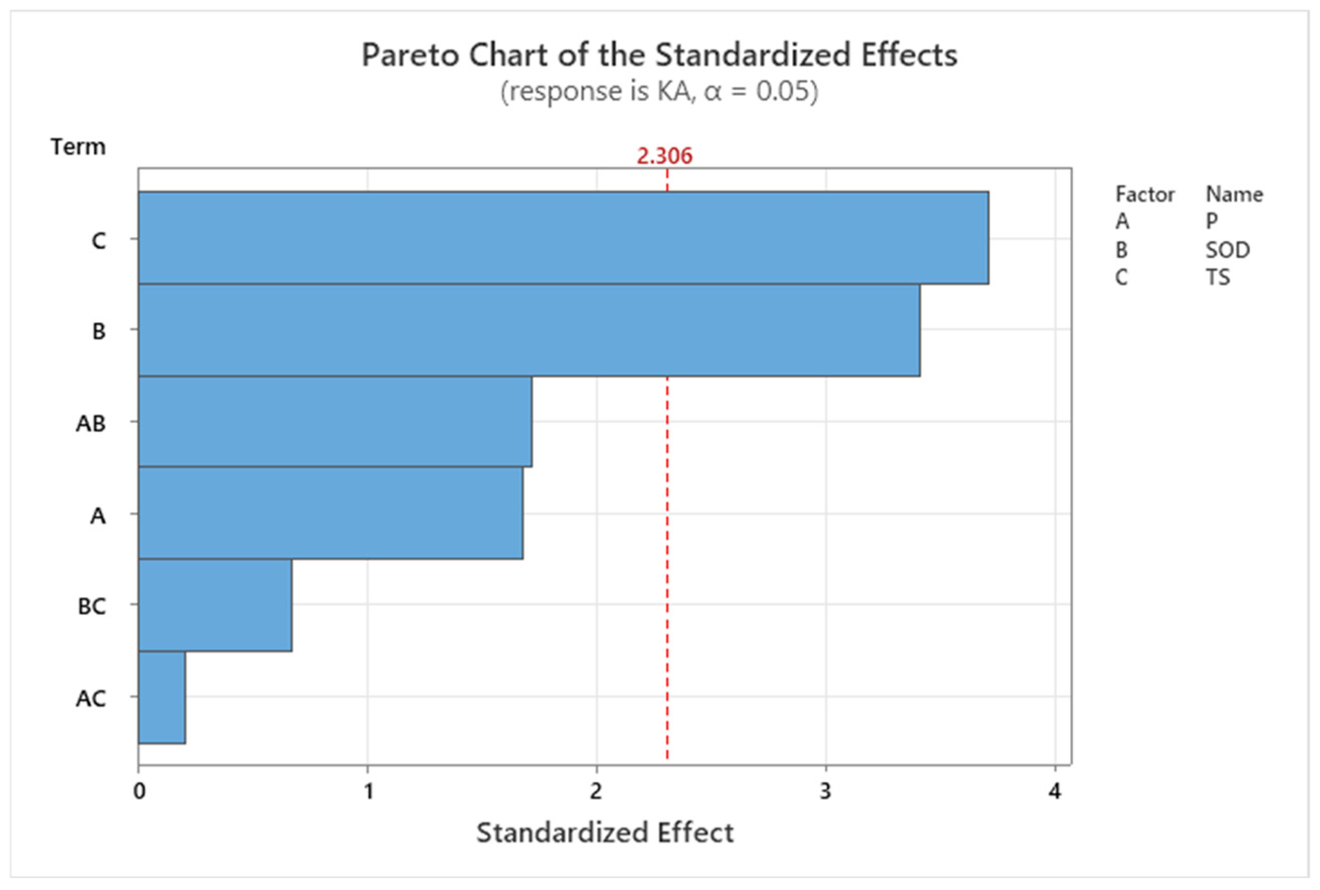
The Pareto chart for the top kerf is shown in Figure 6. It demonstrates that the parameter SOD has the most significant influence on the width of the top kerf. Additionally, the combined effect of SOD and pressure also plays a substantial role in affecting the output. This observation is further supported by the data presented in the ANOVA table.
Figure 6.
The Pareto chart for Kerf Angle.
Figure 7 demonstrates contour plots for the KT. Contour plots use contour lines to represent three-dimensional data in two dimensions. In this case, the plot illustrates the relationship between the output parameter and the variation in two other parameters while keeping a third parameter constant. By examining the areas of lower values on the graph and selecting appropriate levels for the parameters, we can identify the optimal combination to achieve the minimum kerf taper angle. According to the plots, to minimize the kerf taper angle, the parameters TS and SOD should be set to lower levels, while the parameter P should be maintained at a higher level within the specified range.
Figure 7.
Contour plots for Kerf Angle.
3.1.3. Effect of Process Parameters on the Kerf Taper Angle
From the experimental results, it is observed that as the water pressure increases, the kerf taper angle decreases, which matches the findings of previous literature []. The reason behind this is that as the water pressure increases, the kinetic energy of the abrasive particles increases, which enhances their cutting ability and results in a narrower cutting kerf angle. Hence, to maintain a sufficient cutting force, we need to maintain a higher water pressure. From the result, it is also observed that the parameter stand of distance is directly proportional to the kerf angle, which is because, as the stand-off distance increases, when the nozzle is away from the work piece, the abrasive water jet spreads out more before striking the surface and this phenomenon causes the jet to lose its focus and energy which leads to the wider kerf angle []. The next parameter is traverse speed; it is noticed that, as the traverse speed increases, the kerf angle increases. This is because, when the jet moves with a faster rate over the work piece, it spends little time on cutting over a point, which minimizes the cutting ability of the jet to fully penetrate into the work piece with a uniform rate. Hence, the top of the cut becomes wider than the bottom cut, which leads to a wider taper angle [].
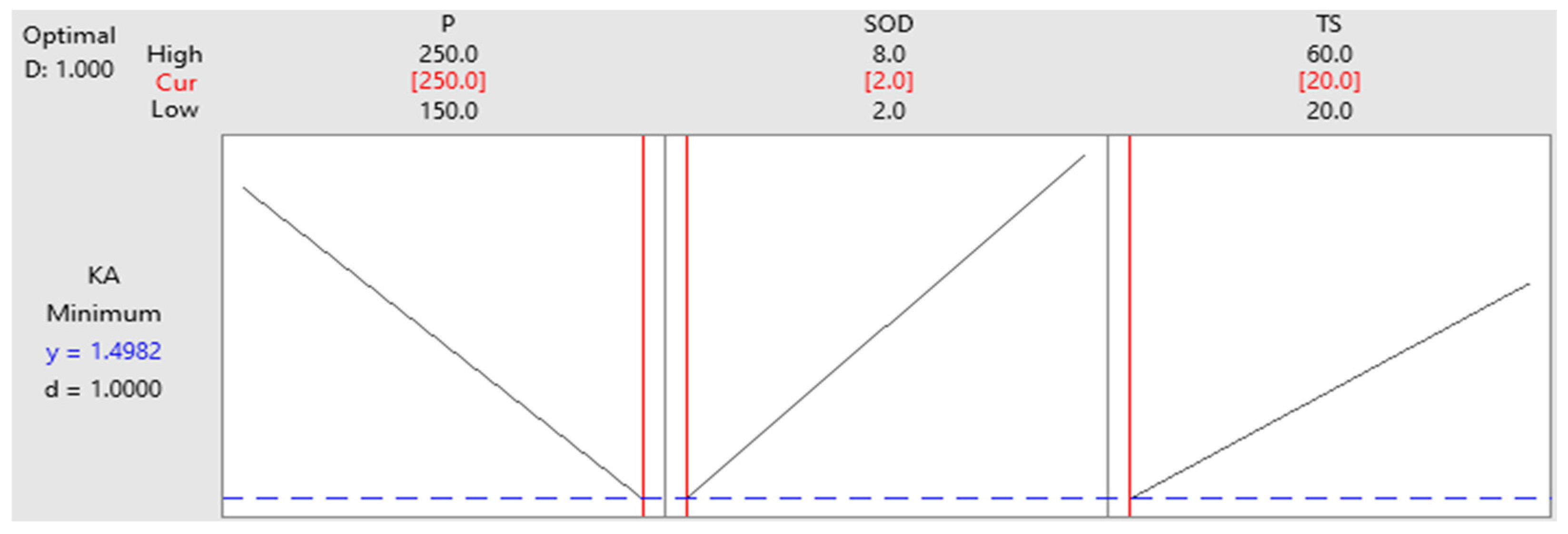
The RSM optimization method is utilized to optimize the levels of process parameters to achieve a lower value of kerf angle. The optimization plot is presented in Figure 8. The optimal levels are highlighted in red. By assigning these levels to each independent parameter, the process can be optimized to minimize the kerf angle. For the present experimentation, the optimal level for parameter P is level 3 (250 MPa). The optimal level for SOD is also level 1 (2 mm), and the optimal level for TS is level 1 (20 mm/min).
Figure 8.
RSM Optimization Plot for Kerf Angle.
3.2. Analysis of Surface Roughness
3.2.1. Regression Equation for Surface Roughness
The regression equation for machined surface roughness (Ra) is as presented in equation 3. The equation demonstrates that the parameters P and SOD have a negative effect on the surface roughness. Additionally, it confirms that when the traverse speed increases, the surface roughness will increase. The other two options have a beneficial effect on the bottom kerf width.
Ra = 3.21 − 0.0071 P − 0.096 SOD + 0.0145 TS + 0.00122 P * SOD + 0.000009 P * TS − 0.00225 SOD * TS
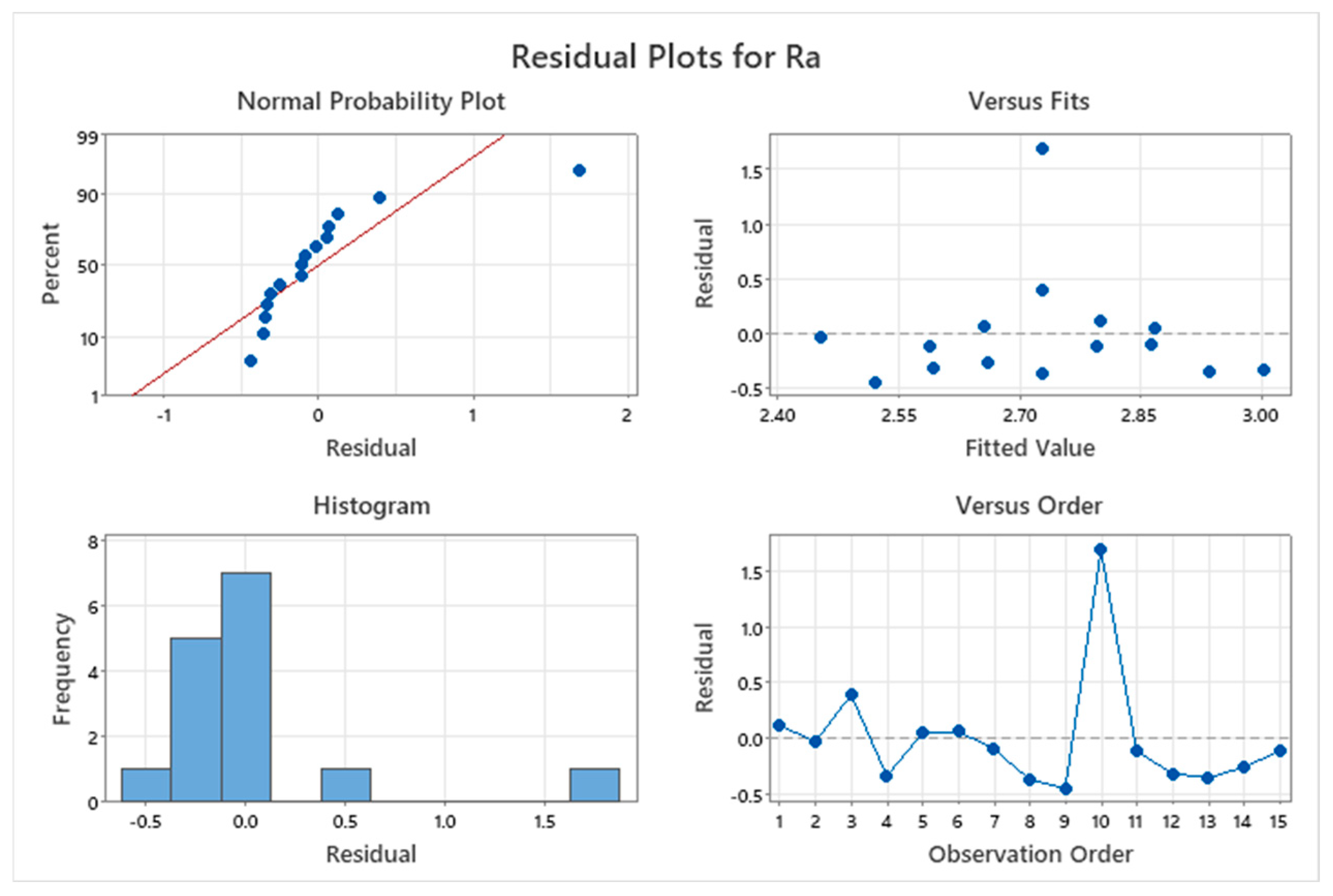
The discrepancy between the observed values and those predicted by the regression model in this experiment is shown by the residual plot, which is shown in Figure 9. With values tightly clustering around the normal distribution line, the normal probability plot, on the other hand, shows that the data collected has a normal distribution. This suggests that the information is appropriate for further examination. Other graphs in Figure 9. The figure also demonstrate the appropriate data distribution and validate the appropriate data collection technique.
Figure 9.
Residual and other plots for Surface Roughness.
Figure 10 displays the main effect plot of the surface roughness. The data shows that the surface roughness is greatly impacted by the parameter SOD. TS stands next to SOD, and P is the least influential one. Therefore, it is recommended to avoid adjusting the values of the SOD parameter with respect to the other two parameters because even a small change in SOD could generate a large variation in surface roughness.
Figure 10.
Main effect plot for Surface roughness.
3.2.2. ANOVA for Surface Roughness
Table 4 represents the roughness of the surface ANOVA. The p-value indicates that the parameters TS and SOD have a significant influence on surface roughness. SOD is the most crucial of these. In contrast, the parameter P has little effect on surface roughness. When combined effects are considered, the interaction between P and SOD has a greater impact on the output parameter.
Table 4.
ANOVA table for Surface roughness.
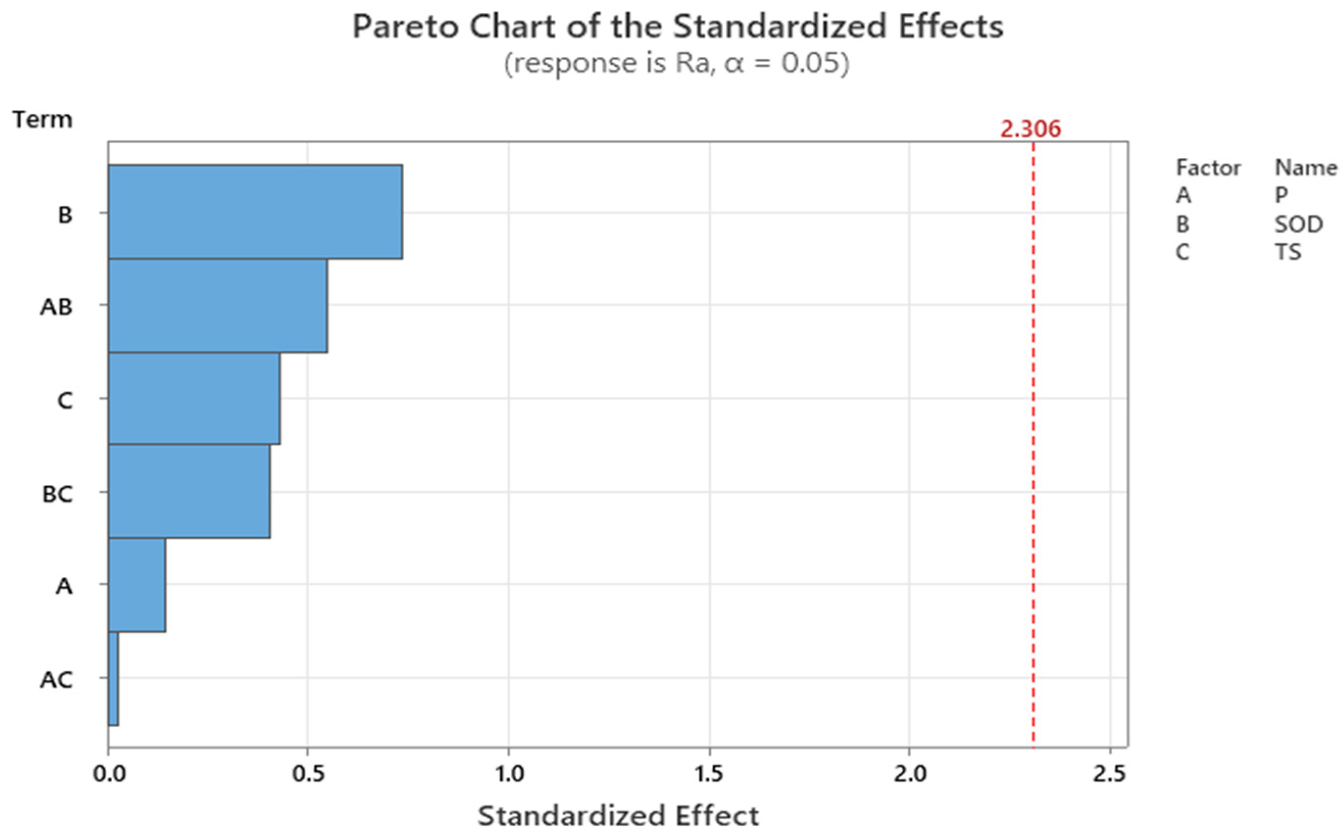
The Pareto chart for the surface roughness is shown in Figure 11. It demonstrates that the SOD parameter has the biggest impact on the breadth of the top kerf. Additionally, the combined action of SOD and pressure has a considerable impact on the output. This insight is further supported by the data displayed in the ANOVA table.
Figure 11.
Pareto chart for Surface roughness.
The contour plots of the surface roughness are displayed in Figure 12. Contour plots are used to display three-dimensional data in two dimensions. It shows the level of the output parameter (surface roughness) in relation to the simultaneous fluctuation of two parameters while holding the other variable constant. By examining the lower value distribution area of the graph and selecting the appropriate parameter levels, one can determine the optimal set of values to achieve the lowest value of surface roughness. The graphs indicate that in order to achieve the minimum top kerf width, the parameters P and SOD should be maintained at a lower level and the parameter TS at a higher level within the range under discussion.
Figure 12.
Contour plot for Surface roughness.
3.2.3. Effect of Process Parameters on the Surface Roughness
The experimental results show that as the jet pressure increases, the surface roughness decreases. This occurs because higher pressure results in greater kinetic energy for the abrasive particles. The increased kinetic energy provides more cutting power for these particles, leading to more effective and uniform cutting of the material. Consequently, a cleaner and deeper cut is achieved []. The results confirm that, when there is an increment in the parameter standoff distance, there is a rise in the surface roughness. This is due to because when the SOD is large, the jet spreads and loses its coherence as it emerges from the nozzle. This reduces the jet’s precision and causes more irregular erosion surfaces, which leads to a rougher surface []. From the result, it is evident that any increment in the traverse speed leads to an increase in the surface roughness. At high traverse speeds, the jet moves quickly across the surface and spends only a little time on cutting action at a point. Hence, it is unable to cut cleanly at that cutting point. This gives rise to incomplete material removal at a point and leads to striation and an irregular surface.
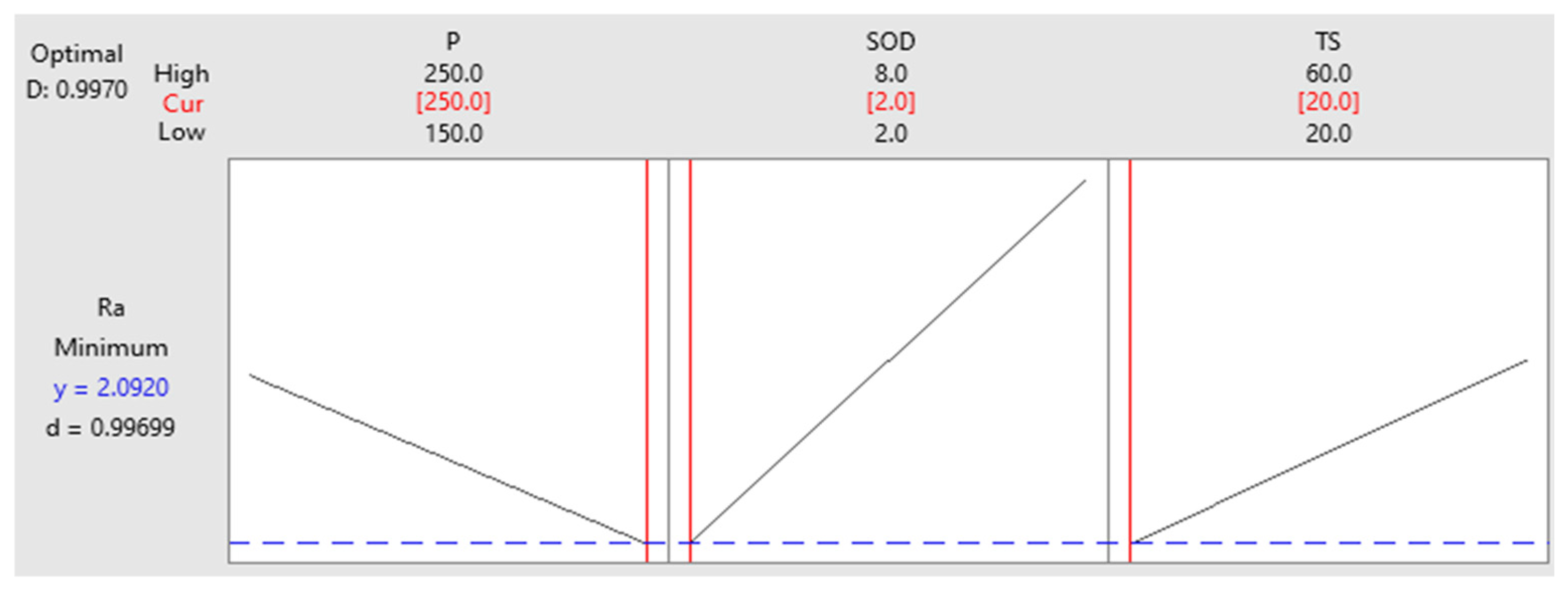
In the present work, the RSM optimization approach is used to optimize the levels of process parameters to reduce the machined surface roughness. Figure 13 displays the optimization plot. The red highlights indicate the ideal levels. It is possible to optimize the process to reduce the surface roughness by allocating these levels to each independent parameter. Level 3 (250 MPa) is the ideal level for parameter P in the current experiment. Level 1 (2 mm) is also the ideal level for SOD, and level 1 (20 mm/min) is the ideal level for TS.
Figure 13.
RSM optimization plot for Surface roughness.
4. Conclusions
In this study, the effects of abrasive water jet machining (AWJM) process parameters, namely water pressure, stand-off distance (SOD), and traverse speed (TS), on the kerf taper angle and surface roughness of a hybrid composite comprising glass, aramid, and jute fibers were thoroughly investigated. Response Surface Methodology (RSM) was employed to model and optimize the process parameters to achieve minimal kerf taper and surface roughness.
The experimental results indicate that water pressure has an inverse relationship with both the kerf taper angle and surface roughness; increasing pressure enhances cutting efficiency and reduces both metrics. In contrast, both stand-off distance and traverse speed were found to have a direct and significant effect; higher values lead to increased kerf taper and rougher surfaces. Among the parameters, stand-off distance emerged as the most influential factor affecting both kerf quality and surface finish.
The RSM optimization revealed that the optimal settings for achieving the minimum kerf taper angle (1.4982°) and surface roughness (2.0920 µm) are a high water pressure of 250 MPa, a low stand-off distance of 2 mm, and a low traverse speed of 20 mm/min. These results validate the importance of precise control over AWJM parameters for the effective machining of hybrid composites and contribute valuable insights for industries where high-dimensional accuracy and surface integrity are critical.
Future work should focus on investigating the effect of abrasive particle size, alternative fiber compositions, and nozzle wear on machining performance, further extending the applicability of AWJM for advanced composite materials.
Author Contributions
Conceptualization, S.M.B., M.B.R.N. and A.H.; methodology, S.M.B.; formal analysis, A.H.; investigation, S.M.B., S.K., H.S.R. and G.B.M.; resources, H.S.R., G.S.M.C. and G.B.M.; data curation, S.M.B., M.B.R.N., A.H. and S.K.; writing—original draft preparation, S.M.B.; writing—review and editing, M.B.R.N., A.H., G.S.M.C. and S.K. All authors have read and agreed to the published version of the manuscript.
Funding
This research received no external funding.
Data Availability Statement
Data is contained within the article.
Conflicts of Interest
The authors declare no conflicts of interest.
References
- Nassar, M.M.A.; Arunachalam, R.; Alzebdeh, K.I. Machinability of natural fiber reinforced composites: A review. Int. J. Adv. Manuf. Technol. 2017, 88, 2985–3004. [Google Scholar] [CrossRef]
- Neto, J.; Queiroz, H.; Aguiar, R.; Lima, R.; Cavalcanti, D.; Banea, M.D. A review of recent advances in hybrid natural fiber reinforced polymer composites. J. Renew. Mater. 2022, 10, 561–589. [Google Scholar] [CrossRef]
- Ramesh, M.; Gopinath, A.; Deepa, C. Machining characteristics of fiber reinforced polymer composites: A review. Indian. J. Sci. Technol. 2016, 9, 1–7. [Google Scholar] [CrossRef]
- Dahiya, A.K.; Bhuyan, B.K.; Acharya, V.; Kumar, S. Optimization of process parameters for machining defects of glass fibre reinforced polymer composite machined by AWJM. In Materials Today: Proceedings; Elsevier: Amsterdam, The Netherlands, 2023. [Google Scholar] [CrossRef]
- Ergene, B.; Bolat, Ç. A review on the recent investigation trends in abrasive waterjet cutting and turning of hybrid composites. Sigma J. Eng. Nat. Sci. 2019, 37, 989–1016. [Google Scholar]
- Chichane, A.; Boujmal, R.; El Barkany, A. Bio-composites and bio-hybrid composites reinforced with natural fibers. Mater. Today Proc. 2023, 72, 3471–3479. [Google Scholar] [CrossRef]
- Pathapalli, V.R.; Pittam, S.R.; Sarila, V.; Burragalla, D.; Gagandeep, A. Multi-objective parametric optimization of AWJM process using Taguchi-based GRA and DEAR methodology. Proc. Inst. Mech. Eng. Part E J. Process Mech. Eng. 2023, 238, 2845–2853. [Google Scholar] [CrossRef]
- Palanikumar, K.; Prabhudass, J.M.; Prabha, P.S.; Senthilkumar, N. Sustainable optimization of abrasive water jet machining for MWCNT/bamboo/Kenaf hybrid polymer composites. Int. J. Interact. Des. Manuf. 2025, 19, 3765–3782. [Google Scholar] [CrossRef]
- Virk, G.S.; Singh, B.; Singh, Y.; Sharma, S.; Ilyas, R.A.; Patyal, V. Abrasive water jet machining of coir fiber reinforced epoxy composites: A review. Funct. Compos. Struct. 2022, 4, 014001. [Google Scholar] [CrossRef]
- Ramalingam, T.; Bhaskar, S.; Seshumadhav, K.; Allamraju, K.V. Optimization of process parameters in bi-directional carbon fiber composite using AWJM. Mater. Today Proc. 2018, 5, 18933–18940. [Google Scholar] [CrossRef]
- Dahiya, A.K.; Bhuyan, B.K.; Kumar, S. Abrasive water jet machining of glass fibre reinforced polymer composite: Experimental investigation, modelling and optimization. Int. J. Interact. Des. Manuf. 2023, 17, 1933–1947. [Google Scholar] [CrossRef]
- Ram, K.; Bajpai, P.K. Water Jet Machining of Hybrid Fiber-Reinforced Polymer Composites. In Forming and Machining of Polymers, Ceramics, and Composites; CRC Press: Boca Raton, FL, USA, 2024; pp. 134–143. [Google Scholar]
- Sajan, S.M. Investigation of the Effect of Abrasive Water Jet Machining Parameters on Fiber-Reinforced Epoxy Composite. Master’s Thesis, Kaunas University of Technology, Kaunas, Lithuania, 2025. [Google Scholar]
- Ficko, M.; Begic-Hajdarevic, D.; Cohodar Husic, M.; Berus, L.; Cekic, A.; Klancnik, S. Prediction of surface roughness of an abrasive water jet cut using an artificial neural network. Materials 2021, 14, 3108. [Google Scholar] [CrossRef] [PubMed]
- Sambruno, A.; Bañon, F.; Salguero, J.; Simonet, B.; Batista, M. Kerf taper defect minimization based on abrasive waterjet machining of low thickness thermoplastic carbon fiber composites C/TPU. Materials 2019, 12, 4192. [Google Scholar] [CrossRef] [PubMed]
- Azmir, M.A.; Ahsan, A.K. A study of abrasive water jet machining process on glass/epoxy composite laminate. J. Mater. Process. Technol. 2009, 209, 6168–6173. [Google Scholar] [CrossRef]
- Gopal, P.M.; Kavimani, V.; Arunkumar, K. Multi-objective optimization on abrasive water jet machining of epoxy/glass fiber/grinding wheel particle composite through hybrid optimization technique. Multiscale Multidiscip. Model. Exp. Des. 2023, 6, 697–707. [Google Scholar] [CrossRef]
- Nyaboro, J.N.; Ahmed, M.A.; El-Hofy, H.; El-Hofy, M. Numerical and experimental characterization of kerf formation in abrasive waterjet machining. In Proceedings of the ASME 2018 International Mechanical Engineering Congress and Exposition, Volume 2: Advanced Manufacturing, Pittsburgh, PA, USA, 9–15 November 2018; Volume 52019, p. V002T02A050. [Google Scholar] [CrossRef]
- Madhu, S.; Balasubramanian, M. Challenges in abrasive jet machining of fiber-reinforced polymeric composites–a review. World J. Eng. 2021, 18, 251–268. [Google Scholar] [CrossRef]
- Deepak, D.; Davim, J.P. Multi-response optimization of process parameters in AWJ machining of hybrid GFRP composite by grey relational method. Procedia Manuf. 2019, 35, 1211–1221. [Google Scholar] [CrossRef]
- Saravanakumar, S.; Sathiyamurthy, S.; Vinoth, V. Enhancing machining accuracy of banana fiber-reinforced composites with ensemble machine learning. Measurement 2024, 235, 114912. [Google Scholar] [CrossRef]
- Jagadish; Bhowmik, S.; Ray, A. Prediction and optimization of process parameters of green composites in AWJM process using response surface methodology. Int. J. Adv. Manuf. Tech. 2016, 87, 1359–1370. [Google Scholar] [CrossRef]
- Jani, S.P.; Senthil Kumar, A.; Adam Khan, M.; Uthayakumar, M. Surface roughness and morphology studies on machining hybrid composite material using abrasive water jet cutting process. In Surface Engineering of Modern Materials; Gupta, K., Ed.; Springer: Cham, Switzerland, 2020; pp. 125–148. [Google Scholar] [CrossRef]
- Yang, X.; Lin, X.; Li, M.; Jiang, X. Experimental study on surface integrity and kerf characteristics during abrasive waterjet and hybrid machining of CFRP laminates. Int. J. Precis. Eng. Manuf. 2020, 21, 2209–2221. [Google Scholar] [CrossRef]
- Peržel, V.; Hloch, S.; Tozan, H.; Yagimli, M.; Hreha, P. Comparative analysis of abrasive waterjet (AWJ) technology with selected unconventional manufacturing processes. Int. J. Phys. Sci. 2011, 6, 5587–5593. [Google Scholar] [CrossRef]
- Subramanian, M.; Selvam, R.; Balasubramanian, T.; Madhusuthan, A.V. Optimum cutting performance of AWJM for Fiber/Metal hybrid composites using GRA-ANN methods. In Materials Today: Proceedings; Elsevier: Amsterdam, The Netherlands, 2024. [Google Scholar] [CrossRef]
- Karthikeyan, R.; Madhu, S.; Geo Varuvel, E.; Pethuthraj, M. Influence of brown algae filler and process parameters on the surface roughness and MRR of jute fiber polymeric composite machined by abrasive water jet. Proc. Inst. Mech. Eng. Part E J. Process Mech. Eng. 2024, 09544089241288069. [Google Scholar] [CrossRef]
- Manjunath Patel, G.C.; Jagadish; Kumar, R.S.; Swamy Naidu, N.V. Optimization of abrasive water jet machining for green composites using multi-variant hybrid techniques. In Optimization of Manufacturing Processes; Springer International Publishing: Cham, Switzerland, 2019; pp. 129–162. [Google Scholar] [CrossRef]
- Pragadish, N.; Kaliappan, S.; Natrayan, L.; Selvam, M.; Patil, P.P.; Arvinda Pandian, C.K. A short review on AWJM of natural fibre reinforced composite materials. Appl. Mech. Mater. 2023, 912, 123–139. [Google Scholar] [CrossRef]
- Murthy, B.R.N.; Makki, E.; Potti, S.R.; Hiremath, A.; Bolar, G.; Giri, J.; Sathish, T. Optimization of process parameters to minimize the surface roughness of abrasive water jet machined jute/epoxy composites for different fiber inclinations. J. Compos. Sci. 2023, 7, 498. [Google Scholar] [CrossRef]
- Kumar, J.; Soota, T.; Rajput, S.K. Optimization and measurement of kerf width and surface roughness of AISI 316L. Forces Mech. 2022, 6, 100071. [Google Scholar] [CrossRef]
- Khan, M.A.; Soni, H.; Mashinini, P.M.; Uthayakumar, M. Abrasive water jet cutting process form machining metals and composites for engineering applications: A review. Eng. Res. Express 2021, 3, 022004. [Google Scholar] [CrossRef]
- Niranjan, C.A.; Srinivas, S.; Ramachandra, M. Experimental investigations on depth of penetration and surface integrity in AZ91/Al2O3 nano-composites cut by abrasive water jet. Int. J. Adv. Manuf. Technol. 2020, 107, 747–762. [Google Scholar] [CrossRef]
- Vijayananth, K.; Muthukutti, G.P.; Ramakrishnan, S.K.; Venkatesan, S.; Zhou, W. An integrated CRITIC-COPRAS approach for multi-response optimization on AWJM of hybrid filler–reinforced polymer composite and its surface integrity. Int. J. Adv. Manuf. Technol. 2024, 131, 4965–4980. [Google Scholar] [CrossRef]
Disclaimer/Publisher’s Note: The statements, opinions and data contained in all publications are solely those of the individual author(s) and contributor(s) and not of MDPI and/or the editor(s). MDPI and/or the editor(s) disclaim responsibility for any injury to people or property resulting from any ideas, methods, instructions or products referred to in the content. |
© 2025 by the authors. Licensee MDPI, Basel, Switzerland. This article is an open access article distributed under the terms and conditions of the Creative Commons Attribution (CC BY) license (https://creativecommons.org/licenses/by/4.0/).