Abstract
Continuous fiber-reinforced ceramic matrix composites (CFRCMCs) are extensively applied in high-temperature fields such as aerospace, energy, and transportation due to their superior mechanical and thermal properties. The explicit and numerical cross-property relations of CFRCMCs are established by integrating a generalized self-consistent scheme, effective-medium conduction models, and finite element analysis. The results reveal that CFRCMCs with a fixed fiber–interphase volume ratio exhibit nearly linear cross-property relations. While the random distribution and diameter of fibers have minimal effects on these relations, a decrease in interphase properties causes the cross-property curves to shift downward. The cross-property relation surfaces for CFRCMCs with varying fiber–interphase volume ratios are validated through finite element analysis. In summary, cross-property relations in CFRCMCs facilitate the prediction of challenging-to-measure physical properties from more readily accessible parameters, substantially simplifying material characterization. This methodology not only optimizes experimental workflows but also delivers a rigorous theoretical framework for multiphysics applications, particularly in extreme thermo-mechanical environments where coupled properties are critical to performance.
1. Introduction
Ceramic matrix composites have garnered considerable attention and application across various fields, including chemistry and mechanical engineering, due to their remarkable mechanical, thermal, and electromagnetic properties and chemical inertness [1,2]. Traditional ceramics encompass a wide array of products, including porcelain, pottery, and glass. More generally, advanced ceramics are defined as materials derived from inorganic non-metallic substances through high-temperature sintering processes. This classification includes a diverse range of materials primarily composed of oxides, such as magnesium oxide, aluminum oxide, and silicon dioxide [3]. Ceramic matrix composites are a rapidly evolving category of advanced materials. The integration of reinforcement phases, such as fiber whiskers, particulates, and platelets, into these composites leads to enhanced toughness, reduced weight, and improved fatigue resistance. These advancements enable ceramic matrix composites to meet the stringent property standards required in various technological domains [4].
Continuous fiber-reinforced ceramic matrix composites (CFRCMCs) represent a notable category of composite materials that employ continuous fibers as the reinforcement phase to improve their material properties. Prominent examples of these composites include Cf/SiC, SiCf/SiC, and Al2O3f/Al2O3, among others [5]. For most CFRCMCs, the fibers and the matrix do not have an ideal connection. Interfaces are artificially formed or generated through chemical reactions [6]. The growing demand for CFRCMCs in high-temperature industries is becoming increasingly significant [7]. This trend is particularly observable in the automotive and railway sectors, where CFRCMCs are used in brake pads; the aerospace sector, where they are applied in engine components, thermal protection systems, and structural elements of satellites; the microelectronics field, where they function as cooling components for various devices; and the energy sector, where they play a crucial role in the fabrication of heat exchangers [8].
In the Non-Metallic Turbine Engine Project conducted by NASA, a CFRCMC material reinforced with 20% SiC fibers was employed in the fabrication of a high-pressure turbine (HPT) nozzle and a cooled doublet vane [9]. General Electric has actively participated in the research and application of CFRCMC materials. For instance, the HPT shrouds of the LEAP engine are constructed from CFRCMC materials, which have collectively achieved over 50 million flight hours to date. CFRCMC components are utilized in five distinct parts of the GE9X engine, comprising one inner combustor liner, one outer combustor liner, the shrouds and nozzles of the HPT Stage 1, and the nozzles of HPT Stage 2 [10]. Zhang et al. have engineered scalable ceramic–polymer composites that utilize three-dimensional interconnected piezoelectric microfoams, which possess the ability to concurrently harvest thermal and mechanical energy. This dual-energy harvesting functionality facilitates their utilization in a diverse range of sensing and energy-generating applications [11].
Hypersonic aerospace vehicles, which operate at velocities surpassing Mach 5, predominantly utilize ultra-high temperature ceramic matrix composites (UHTCMCs) as key materials. These ceramics generally incorporate C/SiC fibers as the reinforcement phase, and ZrB2, ZrC, and other ultrahigh temperature ceramics comprises the matrix materials [12]. Their operational temperatures can exceed 1800 °C, and the melting points of the oxides generated can reach up to 3000 °C [13]. Finally, the German Aerospace Center has successfully developed a UHTCMC material, which incorporates carbon fibers and ZrB2, utilizing the reactive melt infiltration method. This material maintains a flexural strength of 190 MPa even at temperatures as high as 900 °C [14].
Clearly, the predominant areas in which CFRCMCs are applied center on thermo-mechanical coupling at elevated temperatures, a focus that is determined by their superior mechanical and thermal properties. However, the measurement of material properties at high temperatures is often challenging and costly. Consequently, the development of cross-property relations may increase measurement difficulties [15]. Bristow introduced the concept of cross-property correlations, focusing on the relations between elastic modulus and electrical conductivity in solids with low-density, randomly oriented microcracks [16]. Berryman and Milton expanded upon this work by establishing the relations between geometric parameters and material properties in two-phase composite materials [17]. Sevostianov and Kachanov further extended the cross-property relations to anisotropic materials [18].
The properties of composite materials can be described as functions of the same microstructural parameters [19]. By establishing distinct functions for both mechanical and thermal properties and subsequently eliminating microstructural parameters, cross-property relations can be established in the material [20]. This approach allows other properties of the material to be rapidly determined based on one property that is easier to measure [21]. The investigation of cross-property relations has gained considerable attention and been extensively explored in the literature. Sevostianov et al. examined the influence of the tortuosity parameter on effective electrical conductivity and the overall mass transfer coefficient in two-phase materials, subsequently establishing cross-property relations by eliminating this parameter [22].
There are also some studies that focus on the cross-property relations of ceramic matrix composites. Uhlířová et al. examined the relations between elastic properties and conductivity in alumina–zirconia ceramics with varying grain size ratios [23]. Pabst et al. investigated the cross-property relations of alumina ceramics and employed thermal conductivity to predict the shear and bulk moduli of the material [24]. However, current research mainly focuses on two-phase materials composed of fibers and matrices, without considering the significant influence of the interphase on macroscopic property prediction and the establishment of cross-property relations. Moreover, relatively limited attention has been paid to continuous fibers.
In this research, we review current micromechanics property prediction models for CFRCMCs with interfaces. Corresponding representative volume elements (RVEs) are then constructed using voxel elements to verify the models, establishing both explicit and numerical cross-property relations of CFRCMCs. Consequently, one physical property (e.g., mechanical or magnetic) can be predicted from another, more easily measurable quantity (e.g., thermal or electrical). This approach significantly mitigates the challenges associated with measuring material properties in CMCs. Furthermore, by establishing explicit connections between different physical properties, cross-property relations streamline the complexities of multi-objective optimization for these materials. Consequently, they offer substantial promises for advancing multiphysics applications, particularly in demanding thermo-mechanical environments, among others.
This paper is organized as follows: In Section 2, the micromechanics prediction models for CFRCMCs with interfaces are first reviewed. Then, corresponding representative volume elements (RVEs) are constructed using voxel elements to verify the models. Section 3 establishes the cross-property relations of CFRCMCs, including CFRCMCs with a fixed fiber–interphase volume ratio and volume ratios. Finally, the work of this article is summarized, and significant results are presented for guiding engineering measurement and design.
2. Methodology
2.1. The Theoretical Approach Based on Micromechanics Models (MM)
CFRCMCs primarily consist of reinforcing fibers and a ceramic matrix; however, ideal interfacial bonding between these two constituents is rarely achieved. Instead, an interphase region invariably exists, which may originate from chemical interactions between the constituents or be intentionally introduced in the form of a coating to enhance material properties. Consequently, it is essential to conceptualize as three-phase composite systems comprising a fiber phase, matrix phase, and interphase (like a coating). To achieve this, a variety of micromechanics effective medium models can be employed to predict the properties of these three-phase composites. These models have been extensively developed and discussed in previous studies [25,26].
2.1.1. Voigt–Reuss (VR) Bound
Voigt bounds were first proposed by Voigt in 1889. They assume that, under longitudinal loading conditions, the strain in the fiber and the matrix of a composite material is equal to the strain in the effective medium, thereby providing an upper limit for the properties of composite materials. The Voigt upper bounds of the elastic modulus and thermal conductivity for three-phase composites can be derived using Equation (1) [27]:
where , and represent the Young’s modulus of the fibers, the interphase and the matrix. , and represent the Young’s modulus of the fibers, the interphase and the matrix. , and represent the thermal conductivities of the fibers, the interphase, and the matrix.
Reuss bounds, proposed by Reuss in 1929, assume that in a composite material subjected to transverse loading, the stress in the fibers and the matrix is equal to the stress in the effective medium, thereby providing a lower limit for the properties of composite materials. The Reuss lower bounds of the elastic modulus and thermal conductivity for three-phase composites are calculated using Equation (2).
Voigt and Reuss (VR) bounds correspond to the series and parallel connections of the constituent phases, respectively, and are often referred to as the Rule of Mixtures and inverse Rule of Mixtures. Similar bounding expressions can be applied to other mechanical parameters, including the bulk modulus and shear modulus [28]. Since the VR bounds are based on the two extreme idealizations of uniform strain and uniform stress, they generally provide broad estimates of the effective properties [29].
2.1.2. Effective Elastic Properties
The VR bounds identify the limits for the properties of materials. However, in practical scenarios, the notably inferior property of the interphase compared to the other two phases leads to a broad range of bounds, which primarily serve as benchmarks for computational validation [30]. In the context of CFRCMCs, geometric relations among the constituent phases are generally well-defined, which inhibits the realization of these extreme conditions. By examining an RVE with predetermined phase configurations, it is possible to derive analytical expressions for effective material properties. Common approaches for this analysis include the Mori–Tanaka model, generalized self-consistent scheme (GSCS), and bridging model [31]. In this study, GSCS was utilized to establish cross-property relations.
Hashin provided a complete set of calculation formulas for GSCS, wherein the interphase was not considered as a separate phase [32]. Instead, it influenced the stress transfer within the material through interface parameters, thereby simplifying the problem into a two-phase system with non-ideal interfaces. This methodology offers a wider range of applicability, particularly in scenarios where the interphase is challenging to identify and measure. When the properties of the interphase are established, the corresponding property parameters can be efficiently derived from these properties. The subsequent calculation of elastic properties is mainly based on Hashin’s results, and the specific calculation formula is as follows:
For a transversely isotropic thin elastic interphase with a thickness of t, its three interface parameters , and are expressed as Equation (3). The A subscripts correspond to the axial fiber direction, which is designated as Direction-1, and the T subscripts correspond to the normal direction of the fiber, which is designated as Directions-2 and Directions-3. A schematic diagram showing these different directions is provided in Figure 1.
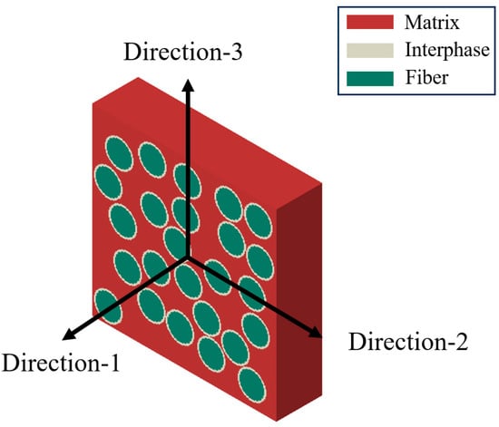
Figure 1.
Directions of RVEs.
After the interface parameters are considered, the effective shear modulus of the fiber with non-ideal interfaces can be expressed as follows:
where a is the radius of fibers. Hashin considered that in some composites, the fibers can be considered as an axis-symmetric structure whose mechanical properties are isotropic in the plane perpendicular to the fiber axis. For transversely isotropic fibers and an isotropic matrix, the effective Young’s modulus , Poisson’s ratio , shear modulus and bulk modulus can be calculated in the axial direction of the material as follows:
Considering the continuity of displacement and stress of the material at the phase boundaries, the shear modulus of the material satisfies the following system of eight linear equations:
where
Here, represents the normalized shear modulus. Under the condition that all fibers possess uniform diameters, GSCS posits that the average strain is consistent across all fibers. As a result, the integration of this premise leads to the derivation of the expression for :
The substitution of Equation (8) into Equation (6) indicates that a solution for Equation (6) exists solely under the condition that . Therefore, the numerator determinant of Equation (6) must vanish. Thus:
The resolution of Equation (9) results in the values of and . Subsequently, the formulas for the computation of and are outlined as follows:
2.1.3. Effective Thermal Conductivity
Currently, a variety of models have been proposed to predict the effective thermal conductivity of CFRCMCs [33]. Notably, the Hasselman–Johnson model and Markworth model explicitly incorporate the interphase. These methodologies primarily consider the interphase in relation to its geometric characteristics and corresponding thermal resistance, a conceptual framework that parallels the modeling of mechanical properties.
Hasselman and Johnson are pioneers in quantifying the impact of inclusion size on effective thermal conductivity [34]. The material is treated as a two-phase system comprising fibers and matrix, with the interphase exerting its influence through the fiber dimension a and boundary conductivity . When the Hasselman–Johnson model is utilized in the context of CFRCMCs, the in-plane effective thermal conductivity is expressed as follows:
Markworth employed effective-medium theory and treated the material as a three-phase system [35]. The entire model is composed of a coaxial cylindrical structure made of three materials. The outermost layer is the matrix phase, the innermost layer is the fiber phase, and the middle layer is the interphase. The expression for the in-plane effective thermal conductivity derived from the Markworth model is as follows:
where w is the thickness of the interphase, and represent the radius of the fiber and matrix. When w is significantly smaller than , represents the fiber volume fraction.
The Hashin model is expressed through mathematical analogy. Although originally formulated for two-phase materials [36], it can be extended to predict the effective thermal conductivity of three-phase materials by systematically considering pairwise phase combinations as follows:
It should be noted that all three previously discussed heat conduction models provide information on in-plane effective thermal conductivity. Consequently, the fiber-direction value, which aligns with the microstructural configuration described by the Voigt upper bound, can be directly assessed using the classical Voigt formula.
2.2. Computational Micromechanics Model Using Voxel Elements (CMM-VE)
2.2.1. Generation of RVE
To thoroughly validate the theoretical framework, it is essential to create an RVE that can undergo finite element analysis (FEA) to ascertain its effective mechanical and thermal properties. The RVE is constructed to accurately represent the microstructural characteristics of CFRCMCs and comprises three distinct phases in accordance with the theoretical formulation: the fiber, interphase, and matrix.
Determining an appropriate RVE size is essential to ensure the reliability of FEA. An RVE that is insufficiently small is unable to adequately represent the stochastic characteristics of fiber distribution, while an excessively large RVE imposes prohibitive computational demands. Heinrich et al. conducted a systematic investigation into the impact of RVE size on the predicted effective properties, concluding that a statistically significant RVE for unidirectionally random fiber distributions should encompass no fewer than twenty-five fibers [37]. Consequently, most of the RVEs utilized in this study contain twenty-five fibers. The validity of this selection is further supported in Section 3.1.2, where the predicted responses of multiple RVEs are analyzed; the slight variation observed among the results indicates that the chosen RVE dimensions are representative. This study examines the stochastic phase distribution, specifically concentrating on the random arrangement of fibers within the matrix. It is important to note that the interfacial layer on the surface of the fibers in actual CFRCMCs exhibits a non-uniform nature. However, the thickness of this interfacial layer is significantly less than that of the fiber itself. As a result, both the fiber and the interphase are modeled as coaxial cylinders within the RVE.
To efficiently produce RVEs that meet the specified morphological criteria and facilitate subsequent meshing processes, a voxel-based discretization approach is applied. Initially, the distributions of fibers and interphases are stochastically generated on a two-dimensional plane, which is subsequently partitioned into a uniform grid composed of square elements. Each element acquires the material properties associated with the phase located at its centroid.
The main limitation of using voxel grids lies is that the boundaries of the grids are either horizontal or vertical, making it difficult to accurately simulate the boundaries of curves. While this discretized representation results in a geometric discrepancy compared to the actual cylindrical fiber morphology, the associated error diminishes significantly when the fiber radius surpasses ten element lengths (R ≥ 10 elements). Finally, the two-dimensional mesh is extended along the fiber axis to create a comprehensive three-dimensional voxel grid. To optimize the allocation of computational resources, a high in-plane resolution is utilized to precisely represent the cross-sectional geometry of the fibers and interphases, and a relatively coarser discretization is implemented in the fiber direction. The procedure for generating the RVE is presented in Figure 2.
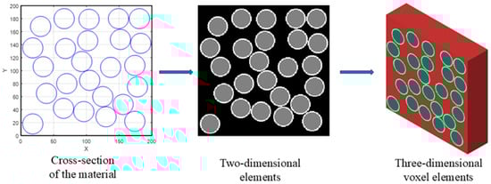
Figure 2.
Model generation of RVEs.
2.2.2. Estimation of Elastic Property
Following the construction of the RVE, the mechanical model is validated by assessing the mechanical properties and volume fractions of every constituent phase, as summarized in Table 1. These values were obtained from reference [38]. Although the properties of the fibers found in the current literature are presented in an isotropic material, the computational model established in Section 2.1.2 for transversely isotropic fibers are still holds true.

Table 1.
The mechanical properties and volume fractions of phases.
In the cited reference, the fiber exhibits a diameter of , which is enveloped by a coating that is thick. Accordingly, a mesh size of is chosen; each fiber consists of 20 elements arranged throughout its diameter, which is encased in a two-element-thick surface coating. The RVE dimensions are determined from the fiber volume fraction, yielding an RVE of elements with an actual physical size of .
Subsequently, periodic boundary conditions (PBCs) are applied to the RVE to mitigate edge effects and facilitate the determination of its effective macroscopic mechanical properties. The homogenized mechanical properties are ascertained by independently applying unit mechanical loads along various directions to the RVE. The FEA process is conducted within ABAQUS utilizing the easyPBC plugin [39].
Taking the computational result of E22 as an example, the corresponding field of stress and strain is illustrated in Figure 3. Here, the maximum tensile stress within the fibers occurs along the loading direction, while the maximum strain occurs transversely to the loading direction. When fibers are sufficiently close in the direction parallel to the applied load, their individual stress-concentration zones overlap and increase in intensity; a concomitant increase is also experienced in strain. Therefore, optimizing the arrangement of the fibers, such as implementing a hexagonal packing configuration, has the potential to improve the effective stiffness of the composite.
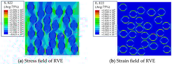
Figure 3.
FEA of E22 for the RVE of mechanical properties.
The effective properties of the RVE are subsequently estimated utilizing the theoretical model outlined in Section 2.1.2, and these predictions are compared with the results obtained from the FEA. A summary of these comparisons is presented in Table 2. The overall error observed is relatively minor, with all values maintained within a 10% threshold. The most significant errors are noted in G12 and G13, which exhibit errors of 7.2% and 7.8%. These discrepancies may be attributed to the varying material properties present between the voxel grids in the oblique direction. In general, the results obtained from FEA and the theoretical solutions corroborate each other, indicating their suitability for the subsequent establishment of cross-property relations.
Table 2.
Comparison between mechanical theoretical results and FEA.
2.2.3. Estimation of Thermal Conductivity
The RVE of thermal properties was constructed using the same methodology and subsequently validated. The thermal property and volume fractions of the phases were derived from reference [40], as illustrated in Table 3.
Table 3.
The thermal properties and volume fractions of phases.
The fibers utilized in the material have a diameter of . The surface coating of these fibers comprises five layers of pyrolytic carbon (PyC) and four layers of SiC, with a total thickness of ; the entire coating is considered as a single entity. Given that the dimensions of the coating are significantly smaller than those of the fiber, the size of a single voxel unit is set to . Consequently, the fiber diameter is represented by 36 voxel units. Based on the fiber volume fraction, the size of the RVE is determined to be voxel elements, which corresponds to an actual physical size of .
Analogous to the calculation of effective mechanical properties, PBCs are imposed on the RVE. In detail, a prescribed temperature is fixed at one end of the RVE and a steady surface heat flux is applied to the opposite face, enabling the calculation of the effective thermal conductivity. Taking the calculation of k22 as an example, the resulting heat flux field and temperature gradient are illustrated in Figure 4.
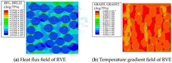
Figure 4.
FEA of k22 for the RVE of the thermal property.
Fiber-direction effective thermal conductivities are calculated using the Voigt bound, and in-plane effective thermal conductivities of the material are subsequently calculated using the Hasselman–Johnson, Markworth, and Hashin models. The results of these calculations are presented in Table 4.
Table 4.
Comparison between thermal theoretical results and FEA.
The numerical results indicate that the effective conductivity in the fiber direction is slightly lower than the Voigt bound, indicating that the latter can be utilized for predictions. For the in-plane properties, both the Hasselman–Johnson and Markworth models demonstrated significant variances, which could be attributed to the high inclusion volume fraction (46% fiber + 5% interphase = 51%), which is in agreement with findings from the literature [33]. The reason for this is that their main limitations are what they fundamentally rely on to solve individual inclusions in an infinitely large matrix. This can be extended to the case of a finite volume fraction through various reasonable but not strictly rigorous assumptions. However, when the volume fraction is relatively high, the deviations brought about by these assumptions become increasingly significant [41].
By contrast, the Hashin model exhibits a significantly smaller deviation, and therefore, it is selected for the subsequent determination of effective thermal conductivity to establish cross-property relations.
3. Results
3.1. Cross-Property Relations of CFRCMCs with a Fixed Fiber–Interphase Volume Ratio
For a subset of CFRCMCs in which the interphase thickness on each fiber is meticulously designed, the ratio of the fiber radius to interphase thickness is effectively constant. As a result, the volumetric ratio between the fiber and interphase is also constant. In these materials, the fiber volume fraction is sufficient to ascertain the volumetric fractions of all three constituent phases.
3.1.1. Establishment of Cross-Property Relations
In the current theoretical frameworks employed for predicting the effective properties of multiphase materials, the apparent behavior is assumed to be governed solely by the intrinsic properties and volume fractions of the constituent phases, with the intrinsic properties fixed at the outset of material design. For CFRCMCs characterized by a prescribed fiber–interphase volume ratio, once the fiber volume fraction is specified, the effective properties can be unambiguously determined, thereby enabling the construction of the material’s cross-property relations.
Owing to the limited availability of open-literature data reporting the constituent-phase properties of CFRCMCs, the data properties and volume fractions used to establish the cross-property relations are drawn from the reference of CMCs and subsequently simplified, with a fiber diameter of , as shown in Table 5 [42].
Table 5.
The properties of phases.
Initially, the effective properties of the materials are predicted using theoretical models. Accounting for the fiber-to-interphase volume ratio, the fiber volume fraction is prescribed over the interval [0, 0.69] with a uniform increment of 0.01. The corresponding effective properties are presented in Figure 5.
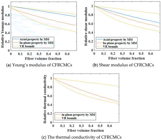
Figure 5.
The effective properties of CFRCMCs with a fixed fiber–interphase volume ratio.
As illustrated in Figure 5, aside from the significant deviation observed in Young’s modulus predictions at a very low fiber volume fraction, most of the calculated values fell within the Voigt–Reuss bounds and can, therefore, be considered reliable. By eliminating the variable of relative density, cross-property relations of mechanical properties and thermal properties for CFRCMCs can be established, as shown in Figure 6.

Figure 6.
Cross-property relations of CFRCMCs with a fixed fiber–interphase volume ratio.
As illustrated in Figure 6, the cross-property relations derived for the selected material parameters are essentially rectilinear. The slope of the axial cross-property relation is smaller than its in-plane counterpart, and the slope characterizing the cross-property relation between Young’s modulus and thermal conductivity is marginally lower than that governing the relation between shear modulus and thermal conductivity.
3.1.2. Random Distribution
For the present material, considering the fiber diameter, the dimensions of a single voxel unit are established at . Consequently, the fiber diameter corresponds to 20 voxel units, while the interface phase thickness is 2 voxel units. The RVE is thus determined to have a size of voxels, which translates to a physical size of . To substantiate the selected RVE size, it is essential to clarify the impact of random fiber distribution on effective material properties. Accordingly, five RVEs are generated at the phase volume fractions corresponding to the pristine material, varying solely in the spatial configuration of the fibers. Figure 7 illustrates the phase distributions within each RVE, with the fiber, interphase, and matrix phases represented by green, white, and red colors, respectively.
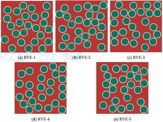
Figure 7.
The phase distributions of different RVE models.
Finite element analysis was performed on the generated RVEs, and the computed properties were subsequently compared with the established cross-property relations. The results are presented in Figure 8. It should be noted that the axial shear modulus and the in-plane thermal conductivity did not completely correspond. The axial cross-property relations established are those between G12, G13, and k11, and the in-plane cross-property relations are those between G23 and k22, k23.
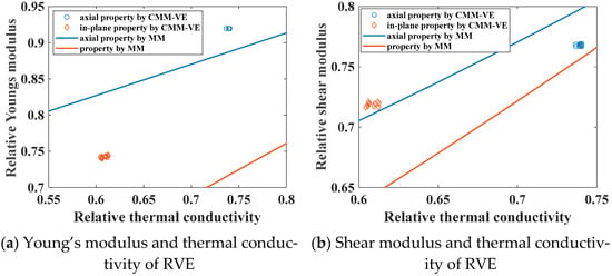
Figure 8.
Cross-property relations of RVE.
Based on the effective properties obtained from homogenization, the distribution of RVE properties is highly concentrated. The largest discrepancy is observed for in-plane thermal conductivity, the maximum value (42.887 WM−1K−1) occurs for k22 of RVE-4, and the minimum value (42.3 WM−1K−1) occurs for k33 of RVE-5. The relative difference between these two extremes is limited at 1.39%. Consequently, the stochastic spatial distribution of fibers has a negligible influence on effective properties at the current RVE size, confirming their appropriateness.
The data obtained on effective properties can also be employed to validate the applicability of cross-property relations. Assuming that the thermal properties are precisely determined through the experiments, the mechanical properties can be predicted directly via cross-property relations and compared with the FEA results. The largest relative deviation occurred in direction 3 of RVE-1: the shear modulus G23 inferred from k33 is 94.052 GPa, which is 11.5% lower than the FEA value of 106.276 GPa. It can be considered that the material conforms to cross-property relations.
In the present analysis, the theoretical model exhibits certain inaccuracies when predicting the shear modulus of the material. Although these deviations remain within an acceptable range for composite material property measure, they have given rise to an intriguing observation: the in-plane shear modulus calculated using CMM-VE is significantly higher than that obtained from MM, whereas the axial shear modulus is correspondingly lower. As a result, in the cross-property relations of shear modulus, the axial results from CMM-VE closely resemble the in-plane results from MM, and vice versa. This phenomenon is primarily attributed to the overly idealized treatment of the interphase in MM when predicting effective properties in cases where both the fiber phase and the interphase have relatively high volume fractions. Additionally, the inherent properties of all constituent phases contribute collectively to this behavior, further influencing the observed discrepancy.
3.1.3. Fiber Diameter
The fiber diameter constitutes a critical parameter in CFRCMCs. To investigate the effect of fiber diameter on the effective properties, it is varied by ±50% while maintaining a constant RVE size and fiber–interphase volume ratio. Specifically, the fiber diameter is adjusted to and , corresponding to 5 and 15 voxels, respectively. Corresponding RVEs are constructed, as shown in Figure 9. In response to variations in fiber diameter, the quantity of fibers in the RVEs is adjusted proportionally.
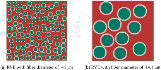
Figure 9.
The RVEs of different fiber diameters.
FEA is performed on the newly developed RVEs, with the effective properties of RVE-1 serving as a proxy for the original fiber diameter. The effective property results obtained are shown in Figure 10. From this, it can be observed that at smaller fiber diameters, the results align more closely with the theoretical model, which is attributable to a more uniform distribution of stress and heat. Nevertheless, the fiber diameter does not compromise the validity of cross-property relations.
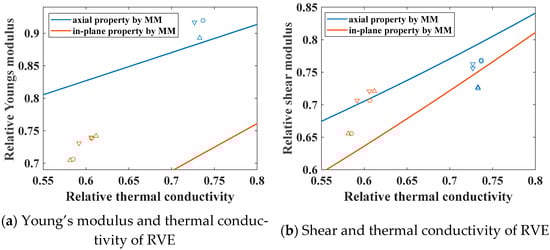
Figure 10.
The properties of RVEs with different fiber diameters. Here, ‘Δ’, ‘O’, and ‘▽’ denote the result of CMM-VE with the fiber diameters of , , and ; blue symbols denote the properties of the axial direction; and orange symbols denote the properties of the in-plane direction.
3.1.4. Interphase
In practical engineering applications, the properties of the fiber and matrix are readily measurable, whereas those of the interphase remain elusive. This difficulty stems from the inherent challenge of precisely defining the interphase domain and the impossibility of isolating it for independent characterization. Consequently, the interphase parameters obtained are unavoidably biased, necessitating a rigorous assessment of their influence on cross-property relations.
Taking RVE1 as the RVE, calculations were performed with the interphase property sets listed in Table 6 to elucidate the influence of interphase properties on cross-property relations. The results obtained from FEA and cross-property relations are both presented in Figure 11. Specifically, property set-1 and set-2 correspond to the interphase properties measured at 600 °C and 1200 °C. Therefore, this result also has some reference value for cross-property relations under high-temperature conditions.
Table 6.
Property sets of the interphase.
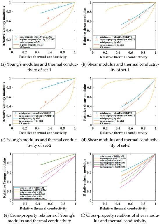
Figure 11.
The influence of interphase properties on cross-property relations.
As illustrated in Figure 11, variations in the properties of the interphase exert a relatively minor influence on the axial cross-property relations between Young’s modulus and thermal conductivity, Especially for the axial cross-property relations, it is approximately coincident in Figure 11e. However, these variations significantly affect all other cross-property relations. A reduction in the interphase properties results in a downward shift in the cross-property relation curves, accompanied by an expansion in the range of these curves. This phenomenon occurs because, for a constant interphase volume fraction, a decrease in the interphase property leads to a decrease in the effective material properties. However, its effect remains comparatively limited.
3.2. Cross-Property Relations of CFRCMCs with Varying Fiber–Interphase Volume Ratios
3.2.1. Establishment of Cross-Property Relations
The preceding discussion focused on the materials of CFRCMCs with a fixed fiber–interphase volume ratio. However, in practical engineering applications, the proportions of each constituent phase exhibit considerable variability in various CFRCMCs. The volume fractions of the fibers and interface phases span a certain range. Consequently, it is essential to develop cross-property relations for CFRCMCs with varying fiber–interphase volume ratios.
The material properties employed are consistent with Section 3.1. For CFRCMCs with varying fiber–interphase volume ratios, effective property calculations necessitate that two of the three constituent phase volume fractions be prescribed. Considering the potential range of component volume fractions, an analysis of existing CFRCMC materials was conducted. The results indicated that a fiber volume fraction within the interval [0, 0.7] and an interface phase volume fraction within the interval [0, 0.3] adequately encompass the majority of currently available CFRCMCs. Analogously, the effective properties are computed at increments of 0.01 over the prescribed ranges of fiber and interphase contents, with the results presented in Figure 12.
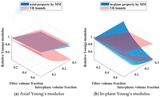
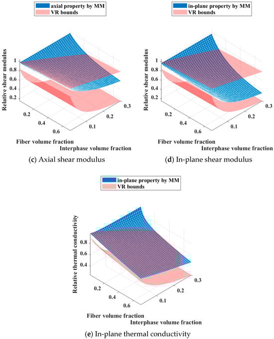
Figure 12.
The effective properties of CFRCMCs with varying fiber–interphase volume ratios.
As illustrated in Figure 12, the effective properties predominantly remain within the VR bounds, indicating the validity of the calculations. Nevertheless, there are instances during the computational process where some properties surpass the VR bounds. This is primarily attributed to inappropriate volume fraction configurations, such as an exceptionally low fiber content coupled with a relatively high proportion of interphase. It is also worth noting that for CFRCMCs with varying fiber-interphase volume ratios, the thickness of the interphase will affect the surface/volume ratio of the equivalent fibers, and thus may have an impact on their effective properties and corresponding cross-property relations.
Additionally, the present model exhibits certain discrepancies in the estimation of the in-plane Young’s modulus. The effective properties of each composite are jointly influenced by the fiber volume fraction and the interphase volume fraction. As a cross-property relation eliminates only one independent variable, the fiber volume fraction is adopted as the Z-axis, thereby permitting the three-dimensional surface representation of the cross-property relations in the property space. Based on these calculated effective properties, the corresponding cross-property relations are subsequently established, as illustrated in Figure 13.
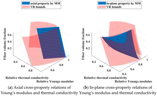
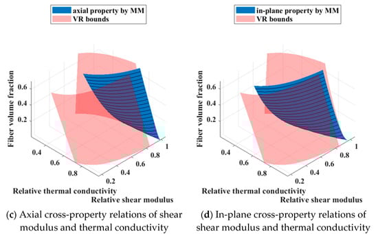
Figure 13.
The cross-property relations of CFRCMCs with varying fiber–interphase volume ratios.
As illustrated in Figure 13, apart from localized regions where the in-plane cross-property relations between Young’s modulus and thermal conductivity marginally exceed the VR bounds, the entire surface remains within the theoretical limits, providing a preliminary validation of the results. Contour lines are further superimposed on the surface. For a composite with a prescribed fiber volume fraction, intersecting the cross-property surface with a horizontal plane at the corresponding height yields the desired curve of cross-property relations for that material. The figure further reveals that, with the selected material parameters, every cross-property relation except for the axial relation between Young’s modulus and thermal conductivity exhibits a marked decrease in the slope of its curve as the fiber volume fraction diminishes. This progressive flattening induces the surface to curl toward a configuration that is increasingly parallel to the thermal conductivity axis.
3.2.2. CMM for CFRCMCs with Varying Fiber–Interphase Volume Ratios
To verify the validity of the cross-property relations established for CFRCMCs with varying fiber–interphase volume ratios, the RVE sizes were held constant and the volume fractions of the fiber and interphase phases were systematically varied. Nine distinct RVEs corresponding to different combinations of fiber and interphase contents were utilized. Their respective volume fractions are listed in Table 7, and the material distributions are illustrated in Figure 14.
Table 7.
Volume fractions of the constituent phases for the different RVE cases.
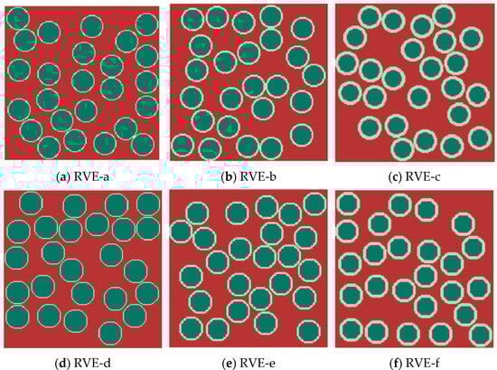
Figure 14.
The phase distributions of different RVE cases.
Homogenization analyses were subsequently performed on each generated RVE to determine the corresponding effective properties, and the results are presented in Figure 15. For the FEA results, the errors associated with in-plane cross-property relations exceed those of their axial counterparts, and Young’s modulus exhibits a marginally higher deviation than the shear modulus. These discrepancies intensify as the fiber volume fraction diminishes, with the in-plane Young’s modulus showing the most pronounced sensitivity. From the perspective of data evolution, the variation trend exhibited by the FEA results closely parallels that of the cross-property relation surface as the fiber volume fraction changes, thereby confirming the validity of the established cross-property relations of CFRCMCs with varying fiber–interphase volume ratios.
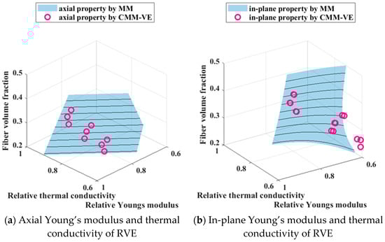
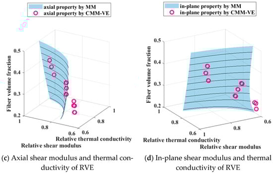
Figure 15.
Sensitivity analysis of RVEs with varying fiber–interphase volume ratios.
4. Conclusions
In this work, a systematic framework is established to derive and validate cross-property relations for CFRCMCs that simultaneously couple elastic and thermal responses. By integrating GSCS, effective-medium conduction models, and statistically representative voxel-based finite-element analysis, the following major findings are obtained:
- For CFRCMCs, self-consistent micromechanics and effective-medium conduction models like the Hashin model can predict the mechanical and thermal properties of materials. However, for cases where the volume fraction of fibers or interphases is too high, the prediction errors are relatively large.
- For CFRCMCs with a fixed fiber–interphase volume ratio, cross-property relations are close to being linear. The slope of the axial cross-property relation is smaller than that of its in-plane counterpart, and the slope characterizing the cross-property relation between Young’s modulus and thermal conductivity is marginally lower than that governing the relation between the shear modulus and thermal conductivity.
- The influence of the random distribution of fibers, fiber diameter, and interphase properties on cross-property relations was analyzed separately. The influence of the former two parameters is relatively small, while a decrease in the interphase properties causes the curve of cross-property relations to shift downward.
- For CFRCMCs with varying fiber–interphase volume ratios, cross-property relation surfaces were established, and FEA verified their correspondence. The errors associated with in-plane cross-property relations exceed those of their axial counterparts, while Young’s modulus exhibits a marginally higher deviation than the shear modulus.
Overall, the findings indicate that CFRCMCs are applicable to cross-property relations. Consequently, one physical property (e.g., mechanical or magnetic) can be predicted from another, more easily measurable quantity (e.g., thermal or electrical). This approach significantly mitigates the challenges associated with measuring material properties in CMCs. Furthermore, by establishing explicit connections between different physical properties, cross-property relations streamline the complexities of multi-objective optimization for these materials. Consequently, they could contribute to advancing multiphysics applications, particularly in demanding thermo-mechanical environments.
To validate this relation, ceramic matrix composites with different fiber volume fractions should be fabricated, and their properties should be characterized individually to evaluate their consistency with the currently established cross-property relations. In addition, more accurate models will be developed to account for the influence of parameters such as interphase thickness on these relations.
Author Contributions
Conceptualization, H.Z., P.L. and S.W.; methodology, P.L., S.W., W.L., C.Z., Z.C., J.D., S.Y., H.Z. and J.J.; software, S.W., Z.C., J.D., H.Z. and J.J.; validation, P.L., S.W., W.L., C.Z., Z.C., J.D. and S.Y.; formal analysis, P.L., S.W., W.L., C.Z. and S.Y.; investigation, P.L., S.W., W.L., C.Z. and Z.C.; resources, C.Z., Z.C., J.D., H.Z. and J.J.; data curation, S.W., J.D. and S.Y.; writing—original draft preparation, P.L. and S.W.; writing—review and editing, W.L., C.Z., Z.C., J.D., S.Y., H.Z. and J.J.; visualization, P.L. and S.W.; supervision, H.Z. and J.J.; funding acquisition, H.Z. and J.J. All authors have read and agreed to the published version of the manuscript.
Funding
This research received no external funding.
Data Availability Statement
The data presented in this study are available on request from the corresponding author due to privacy.
Acknowledgments
The authors acknowledge the technical support of the responsible staff members Zhao Xu, Bin Yu, Liping Xiao and ZiYue Sun at Technology and Engineering Center for Space Utilization, Chinese Academy of Sciences, during the preparation of this study. We also acknowledge Wei Liao, Yana Wang, Jinhua Yang and Hu Liu at AECC Beijing Institute of Aeronautical Materials.
Conflicts of Interest
The authors declare no conflicts of interest.
References
- Shrivastava, S.; Rajak, D.K.; Joshi, T.; Singh, D.K.; Mondal, D.P. Ceramic matrix composites: Classifications, manufacturing, properties, and applications. Ceramics 2024, 7, 652–679. [Google Scholar] [CrossRef]
- Bansal, N.P.; Lamon, J. Ceramic Matrix Composites: Materials, Modeling and Technology; John Wiley & Sons: Hoboken, NJ, USA, 2014. [Google Scholar]
- Heimann, R.B. Classic and Advanced Ceramics: From Fundamentals to Applications; John Wiley & Sons: Hoboken, NJ, USA, 2010. [Google Scholar]
- Radhika, N.; Sathish, M. A review on Si-based ceramic matrix composites and their infiltration based techniques. Silicon 2022, 14, 10141–10171. [Google Scholar] [CrossRef]
- Zhang, J.; Cai, F.; Jin, X.; Chen, X.; Kan, Y.; Dong, S. Progress in research and application of continuous fiber reinforced ceramic matrix composites. J. Ceram. 2023, 44, 195–207. [Google Scholar]
- Tressler, R.E. Recent developments in fibers and interphases for high temperature ceramic matrix composites. Compos. Part A Appl. Sci. Manuf. 1999, 30, 429–437. [Google Scholar] [CrossRef]
- Krenkel, W. (Ed.) Ceramic Matrix Composites: Fiber Reinforced Ceramics and their Applications; John Wiley & Sons: Hoboken, NJ, USA, 2008. [Google Scholar]
- Hofbauer, P.J.; Rädlein, E.; Raether, F. Fundamental mechanisms with reactive infiltration of silicon melt into carbon capillaries. Adv. Eng. Mater. 2019, 21, 1900184. [Google Scholar] [CrossRef]
- Halbig, M.C.; Singh, M. Additive Manufacturing of SiC Based Ceramics and Ceramic Matrix Composites. In Proceedings of the International Conference on Ceramic Materials and Components for Energy and Environmental Applications, Vancouver, BC, Canada, 14–19 June 2015. [Google Scholar]
- Steibel, J. Ceramic matrix composites taking flight at GE Aviation. Am. Ceram. Soc. Bull. 2019, 98, 30–33. [Google Scholar]
- Zhang, G.; Zhao, P.; Zhang, X.; Han, K.; Zhao, T.; Zhang, Y.; Jeong, C.K.; Jiang, S.; Zhang, S.; Wang, Q. Flexible three-dimensional interconnected piezoelectric ceramic foam based composites for highly efficient concurrent mechanical and thermal energy harvesting. Energy Environ. Sci. 2018, 11, 2046–2056. [Google Scholar] [CrossRef]
- Ionescu, E.; Bernard, S.; Lucas, R.; Kroll, P.; Ushakov, S.; Navrotsky, A.; Riedel, R. Polymer-derived ultra-high temperature ceramics (UHTCs) and related materials. In Ceramics, Glass and Glass-Ceramics: From Early Manufacturing Steps Towards Modern Frontiers; Springer International Publishing: Cham, Switzerland, 2021; pp. 281–323. [Google Scholar]
- Binner, J.; Porter, M.; Baker, B.; Zou, J.; Venkatachalam, V.; Diaz, V.R.; D’Angio, A.; Ramanujam, P.; Zhang, T.; Murthy, T.S.R.C. Selection, processing, properties and applications of ultra-high temperature ceramic matrix composites, UHTCMCs—A review. Int. Mater. Rev. 2020, 65, 389–444. [Google Scholar] [CrossRef]
- Baier, L.; Frieß, M.; Hensch, N.; Leisner, V. Development of ultra-high temperature ceramic matrix composites for hypersonic applications via reactive melt infiltration and mechanical testing under high temperature. CEAS Space J. 2024, 17, 635–644. [Google Scholar] [CrossRef]
- Zhao, H.F.; Hu, G.K.; Lu, T.J. Correlation between the elastic moduli and conductivity of two-dimensional isotropic two-phase composites. Int. J. Fract. 2004, 126, L11–L18. [Google Scholar]
- Bristow, J.R. Microcracks, and the static and dynamic elastic constants of annealed and heavily cold-worked metals. Br. J. Appl. Phys. 1960, 11, 81. [Google Scholar] [CrossRef]
- Berryman, J.G.; Milton, G.W. Microgeometry of random composites and porous media. J. Phys. D Appl. Phys. 1988, 21, 87. [Google Scholar] [CrossRef]
- Sevostianov, I.; Kachanov, M. Explicit cross-property correlations for anisotropic two-phase composite materials. J. Mech. Phys. Solids 2002, 50, 253–282. [Google Scholar] [CrossRef]
- Kachanov, M.; Sevostianov, I. On quantitative characterization of microstructures and effective properties. Int. J. Solids Struct. 2005, 42, 309–336. [Google Scholar] [CrossRef]
- Zhao, H.F.; Hu, G.K.; Lu, T.J. Cross-property relations for two-phase planar composites. Comput. Mater. Sci. 2006, 35, 408–415. [Google Scholar] [CrossRef]
- Song, F.; Zhao, H.F.; Hu, G.K. Explicit cross-link relations between effective elastic modulus and thermal conductivity for fiber composites. Comput. Mater. Sci. 2012, 51, 353–359. [Google Scholar] [CrossRef]
- Sevostianov, I.; Trofimov, A.; Merodio, J.; Penta, R.; Rodriguez-Ramos, R. Connection between electrical conductivity and diffusion coefficient of a conductive porous material filled with electrolyte. Int. J. Eng. Sci. 2017, 121, 108–117. [Google Scholar] [CrossRef]
- Uhlířová, T.; Šimonová, P.; Pabst, W. Modeling of elastic properties and conductivity of partially sintered ceramics with duplex microstructure and different grain size ratio. J. Eur. Ceram. Soc. 2022, 42, 2946–2956. [Google Scholar] [CrossRef]
- Pabst, W.; Uhlířová, T.; Gregorová, E. Shear and bulk moduli of isotropic porous and cellular alumina ceramics predicted from thermal conductivity via cross-property relations. Ceram. Int. 2018, 44, 8100–8108. [Google Scholar] [CrossRef]
- Choy, T.C. Effective Medium Theory: Principles and Applications; Oxford University Press: Oxford, UK, 2015. [Google Scholar]
- Raju, B.; Hiremath, S.R.; Mahapatra, D.R. A review of micromechanics based models for effective elastic properties of reinforced polymer matrix composites. Compos. Struct. 2018, 204, 607–619. [Google Scholar] [CrossRef]
- Oli, S.; Luo, Y. Characterization and Design of Three-Phase Particulate Composites: Microstructure-Free Finite Element Modeling vs. Analytical Micromechanics Models. Materials 2023, 16, 6147. [Google Scholar] [CrossRef]
- Kachanov, M. Effective properties of heterogeneous materials as functions of contrast between properties of constituents. Math. Mech. Solids 2024, 29, 2476–2489. [Google Scholar] [CrossRef]
- Kachanov, M.; Sevostianov, I. Micromechanics of Materials, with Applications; Springer: Cham, Switzerland, 2018; Volume 249. [Google Scholar]
- Stefaniuk, D.; Kachanov, M. Voigt-reuss and hashin-shtrikman bounds revisited. Int. J. Eng. Sci. 2023, 191, 103903. [Google Scholar] [CrossRef]
- Wang, Y.C.; Huang, Z.M. Bridging tensor with an imperfect interface. Eur. J. Mech.-A/Solids 2016, 56, 73–91. [Google Scholar] [CrossRef]
- Hashin, Z. Thermoelastic properties of fiber composites with imperfect interface. Mech. Mater. 1990, 8, 333–348. [Google Scholar] [CrossRef]
- Pietrak, K.; Wiśniewski, T.S. A review of models for effective thermal conductivity of composite materials. J. Power Technol. 2015, 95, 14–24. [Google Scholar]
- Powell, B.R., Jr.; Youngblood, G.E.; Hasselman, D.P.H.; Bentsen, L.D. Effect of thermal expansion mismatch on the thermal diffusivity of glass-ni composites. J. Am. Ceram. Soc. 1980, 63, 581–586. [Google Scholar] [CrossRef]
- Markworth, A.J. The transverse thermal conductivity of a unidirectional fibre composite with fibre-matrix debonding: A calculation based on effective-medium theory. J. Mater. Sci. Lett. 1993, 12, 1487–1489. [Google Scholar] [CrossRef]
- Hashin, Z. Analysis of properties of fiber composites with anisotropic constituents. J. Appl. Mech. 1979, 46, 543–550. [Google Scholar] [CrossRef]
- Heinrich, C.; Aldridge, M.; Wineman, A.S.; Kieffer, J.; Waas, A.M.; Shahwan, K. The influence of the representative volume element (RVE) size on the homogenized response of cured fiber composites. Model. Simul. Mater. Sci. Eng. 2012, 20, 075007. [Google Scholar] [CrossRef]
- Mital, S.K.; Arnold, S.M.; Bednarcyk, B.A.; Pineda, E.J. Micromechanics-based modeling of SiC/SiC ceramic matrix composites and structures. Recent Prog. Mater. 2023, 5, 25. [Google Scholar] [CrossRef]
- Omairey, S.L.; Dunning, P.D.; Sriramula, S. Development of an ABAQUS plugin tool for periodic RVE homogenisation. Eng. Comput. 2019, 35, 567–577. [Google Scholar] [CrossRef]
- Pek, E.K.; Brethauer, J.; Cahill, D.G. High spatial resolution thermal conductivity map of SiC/SiC composites. J. Nucl. Mater. 2020, 542, 152519. [Google Scholar] [CrossRef]
- Tavangar, R.; Molina, J.M.; Weber, L. Assessing predictive schemes for thermal conductivity against diamond-reinforced silver matrix composites at intermediate phase contrast. Scr. Mater. 2007, 56, 357–360. [Google Scholar] [CrossRef]
- Murthy, P.L.N.; Mital, S.K.; DiCarlo, J.A. Characterizing the properties of a woven SiC/SiC composite using W-CEMCAN computer code. J. Adv. Mater.-Covina 2003, 35, 52–58. [Google Scholar]
Disclaimer/Publisher’s Note: The statements, opinions and data contained in all publications are solely those of the individual author(s) and contributor(s) and not of MDPI and/or the editor(s). MDPI and/or the editor(s) disclaim responsibility for any injury to people or property resulting from any ideas, methods, instructions or products referred to in the content. |
© 2026 by the authors. Licensee MDPI, Basel, Switzerland. This article is an open access article distributed under the terms and conditions of the Creative Commons Attribution (CC BY) license.