Abstract
This study evaluates the surface roughness of micromilled 316L stainless steel parts fabricated via fused filament fabrication (FFF) and sintering, establishing statistical links between additive manufacturing and post-machining parameters. The surface roughness of the final part is affected by both 3D printing and micromachining parameters. The presented work has direct practical relevance because micromilled 316L stainless steel components are frequently used in applications such as lab-on-a-chip (LOC) devices and micro-electro-mechanical systems (MEMS), where fatigue behavior and the rheological behavior of fluid flow play critical roles. Both fluid flow and fatigue performance of micromilled components are highly dependent on surface integrity, including surface roughness, residual stresses, and microstructure. Specimens were produced using a 3D printer, under controlled layer thicknesses, raster angles, and fabrication directions, followed by a sintering process for the 3D-printed parts. The sintered parts are then micromilled at varying cutting directions (Angle Cut). Surface roughness (Ra) was measured with a profilometer, generating 34 experimental datasets analyzed through correlation and regression modeling. Cutting direction (Angle Cut) exhibited the strongest positive correlation with Ra (r = 0.486, p = 0.004), followed by layer thickness (r = 0.326, p = 0.060), whereas raster angle and fabrication direction had minimal influence. The multiple linear regression model accounted for 33.5% of Ra variance (R2 = 0.335, p = 0.0158), highlighting that fine-layer deposition and alignment of tool paths with filament orientation significantly improve post-machined surface quality. Results confirm that additive-induced anisotropy persists after sintering, affecting chip formation and surface morphology during micromilling. The novelty of this work lies in its integrated hybrid framework, linking metal FFF process parameters, fabrication direction, and machining outcomes through a unified statistical approach. This foundation supports machine-learning-based prediction and hybrid process optimization in metal FFF systems, providing guidance for high-quality additive–subtractive manufacturing.
1. Introduction
The rapid evolution of additive manufacturing (AM) has revolutionized design and production paradigms across aerospace, biomedical, and energy sectors by enabling the fabrication of complex geometries with minimal tooling and material waste [1]. Several researcher groups have demonstrated that additively manufactured components can achieve densities exceeding 95% after optimized sintering while maintaining mechanical properties comparable to conventionally processed 316L parts [2]. Cerlincă et al. [3] studied manufacturing parameters, including the dimensional accuracy and surface quality, of additively manufactured 316L stainless steel components. Unlike traditional subtractive manufacturing, AM enables near-net-shape fabrication directly from digital models, significantly reducing lead times and expanding design freedom [4]. Among the family of AM processes, fused deposition modeling (FDM)/fused filament fabrication (FFF) has gained considerable attention due to its affordability, accessibility, and growing material diversity [5,6].
In metal FFF, a composite filament containing metallic powder and a polymeric binder is extruded layer-by-layer, producing a green part that undergoes debinding and sintering to achieve a dense metallic structure [7]. This process employs existing FDM infrastructure to produce metallic components without requiring high-energy laser systems, as used in selective laser melting (SLM) or directed energy deposition (DED) [8]. In addition, the optimization of green density and surface roughness in FFF-printed 316L stainless steel polymer blends has been systematically investigated to improve final surface quality and mechanical performance after sintering [9]. Process parameter optimization in extrusion-based metal 3D printing using PW–LDPE–SA binder systems has been shown to significantly influence green-part density, debinding behavior, and final sintered properties [10]. The development of feedstocks such as BASF Ultrafuse 316L, consisting of fine stainless steel powder in a thermoplastic binder, has further extended the industrial relevance of FFF for small-batch, high-complexity metallic parts [11].
Surface quality remains a major limitation in FFF parts. The layer-by-layer deposition generates staircase effects, voids, and interlayer porosity, resulting in surface roughness values (Ra) often exceeding 10 µm, as reported by Sadaf et al. [12]. Wagner et al. [13] further demonstrated that sintering-induced shrinkage and microstructural evolution significantly modify the final surface morphology of FFF-fabricated 316L components. Kaynak and Kitay [14] showed that such surface defects directly degrade the mechanical strength of additively manufactured 316L after finish machining. Greco et al. [15] reported that poor surface quality also leads to reduced fatigue resistance due to stress concentration at surface asperities. Matras [16] demonstrated that corrosion behavior is strongly affected by surface roughness and subsurface defects generated during additive manufacturing and post-processing. He et al. [17] confirmed that these surface irregularities act as critical stress concentrators during the micro-scale machining of additively manufactured alloys. Machno and Zębala [18] showed that dimensional accuracy after milling is significantly influenced by the initial surface condition of 316L parts produced by AM. Montalti et al. [19] further reported that surface defects also serve as potential corrosion-initiation sites, particularly in applications involving aggressive environments or biomedical exposure.
Salvi et al. studied the effects of line width and layer thickness using multi-head MEX 3D printing for fabricating PLA-based shape memory multi-material objects. The authors used FEM simulations for the optimization of the grid geometry followed by experimental investigation of electrical and thermal conductivity values using ANOVA analysis via Minitab 22 software. Their results show that the line width together with the layer thickness affect mechanical properties and electrical resistance [20]. Kurose et al. [21] revealed that voids oriented perpendicular to the tensile direction act as defects that could cause stress concentration, thus resulting in poor mechanical properties. Quarto et al. [22] stated that density and shrinkage in FDM-printed AISI 316L parts are influenced by printing parameters and part geometry. The reduction in surface roughness is thus essential for achieving high-performance, functional components.
A variety of process parameters influence the surface finish in FDM/FFF manufacturing. These include layer thickness, raster orientation, nozzle temperature, feed rate, infill pattern, and build direction. Layer thickness, for example, directly governs the geometric discretization of surfaces—the finer the layer, the smaller the staircase effect [14]. Raster orientation and build direction control interlayer bonding and anisotropy in both surface texture and mechanical response [10]. Caminero et al. [2] systematically quantified these factors, revealing that surface roughness and density exhibit strong nonlinear dependencies on process parameters. However, even under optimized printing conditions, residual porosity and thermal shrinkage during sintering continue to degrade the final surface topography [14]. In recent years, in order to provide not only an attractive appearance at the surface of the 3D printer components but to also improve grip and wettability, modifying mesh topology techniques, such as fuzzy skin methodology where the toolpath is randomly distorted at each layer, have been introduced. Vesco and Salvi are some of the first researchers who investigated the effects of input parameters such as thickness, fuzzy skin point distance, and fuzzy skin thickness on the surface morphology and gripping properties [23].
To address these shortcomings, post-processing and hybrid manufacturing approaches have been extensively investigated. The combination of additive and subtractive techniques—known as hybrid additive–subtractive manufacturing (H-AM)—integrates the geometric flexibility of AM with the precision and surface control of conventional machining [19]. The hybrid concept has also been successfully applied to surface-finishing strategies using mechanically assisted post-processing routes [22]. Additional studies have demonstrated that combining AM with secondary finishing operations significantly enhances dimensional accuracy and surface integrity [24]. Behjat et al. [25] reported that post-treatment strategies influence both surface quality and tensile strength in AM 316L.
Methods such as micromilling [17], ball burnishing [26], mechanical ironing [19], and pulse-reverse electropolishing [24] have been applied to improve surface roughness, remove sintering residues, and enhance microstructural uniformity. For instance, Gorey et al. [24] demonstrated that pulse/pulse-reverse electropolishing can reduce the Ra of FFF 316L parts to near-machined levels, while Montalti et al. [19] employed mechanical ironing and Chueca de Bruijn et al. [26] applied ball burnishing to achieve surface uniformity without significant material removal.
A further challenge arises from the interdependence of density, mechanical strength, and surface roughness. Hassan et al. [27] demonstrated that densification during sintering directly enhances hardness and tensile strength while simultaneously altering the response to micro-cutting forces. Understanding these coupled relationships is therefore essential for defining parameter windows that jointly optimize print quality, mechanical performance, and machinability. Zaitceva et al. [28] investigated the microstructure and mechanical properties of 316L stainless steel fabricated by FDM and demonstrated that layer-driven anisotropy and residual porosity significantly influence tensile strength, ductility, and overall mechanical performance after sintering. Soler et al. [29] applied ANN techniques to predict finishing-process roughness with high accuracy. Mukherjee et al. [30] used structured light characterization to enhance AM surface-quality modeling. Betts et al. [31] optimized Ultrafuse 316L process parameters to minimize process-induced porosity and improve sintered density. Suresh et al. [32] reviewed recent advances in in situ three-dimensional surface topographical monitoring techniques for additive manufacturing, highlighting their importance for real-time defect detection, surface-quality control, and closed-loop process optimization. Tran and Phan [33] applied machine learning techniques to analyze the combined effects of FDM process parameters on surface roughness and mechanical properties, demonstrating that data-driven models significantly improve predictive accuracy compared with conventional statistical methods.
Integration of surface-quality prediction with process-parameter selection in fused deposition modeling has been demonstrated to significantly improve dimensional accuracy and surface integrity through coupled analytical–empirical modeling frameworks [34]. Rajhi et al. [35] applied response-surface methodology (RSM) to model the influence of FFF process parameters on surface quality in TPU composites. Zhang and Yuan [36] systematically investigated surface roughness on vertically built 316L stainless steel components fabricated by LPBF and demonstrated that gravity-driven melt-pool dynamics and layer-wise solidification significantly influence directional roughness formation and surface morphology. Dias et al. [37] demonstrated that data-driven monitoring strategies improve surface-quality control in WAAM systems. Mushtaq et al. [38] showed that nozzle temperature and feed rate strongly influence surface roughness in polymer-based FFF of ABS and Nylon-6. La Fé-Perdomo et al. [39] developed statistical and machine-learning-based regression models to predict the surface roughness and mechanical properties of SLM-fabricated 316L stainless steel, demonstrating that ML approaches significantly improve prediction accuracy compared with traditional linear regressors. Yang et al. [40] investigated rough-surface characterization and established redundant parameter sets for surface modeling, showing that multiple surface descriptors must be considered simultaneously to accurately capture anisotropic roughness behavior. Kim et al. [41] reported that post-processing operations significantly alter the mechanical behavior of additively manufactured 304L stainless steel. In polymer-based systems, Mishra et al. [42] used ANOVA to evaluate the influence of layer height, infill density, and print speed on the mechanical and surface behavior of wood–PLA composites. Process optimization of metal FFF materials has also received recent attention. Kumaresan et al. [43] reported that optimization of PETG-based FDM parameters significantly enhances mechanical strength and surface integrity.
Micromilling represents one of the most controllable and scalable finishing methods for metallic additively manufactured parts. Matras [16] demonstrated that the direction of cutting relative to the additively manufactured layer orientation strongly influences surface roughness and cutting stability in SLM-fabricated steels. Greco et al. [15] further showed that the directionality of micromilling with respect to the layer-wise microstructure significantly affects the cutting forces, chip segmentation, and surface morphology of AM 316L components. The distinct layered microstructure inherent to FFF and SLM parts induces direction-dependent cutting resistance and intermittent chip formation. Machno and Zębala [18] reported that microstructural heterogeneity and residual porosity cause nonuniform tool–material interactions during post-processing, leading to localized ploughing and asymmetric tool marks. These findings collectively demonstrate that evaluating multi-directional micromilling performance is essential for understanding the machinability of additively manufactured 316L stainless steel.
Although empirical post-processing studies have demonstrated measurable improvements in surface integrity, the quantitative prediction of surface roughness remains a formidable challenge. Elkaseer et al. [44] employed experiment-based modeling and optimization strategies to establish resource-efficient parameter windows in FFF processing. Sharma et al. [45] developed machine-learning models for roughness prediction in dental AM components using statistical regression frameworks. Chen et al. [46] modeled top-surface roughness in robotic wire-arc additive manufacturing using process–response relationships. Batu et al. [47] demonstrated that artificial-intelligence-based modeling significantly improves surface roughness prediction accuracy for AM components.
In metal AM, Matras [16] correlated scanning speed and cutting direction with surface roughness through statistical modeling. Machno and Zębala [18] also applied regression-based approaches to associate machining parameters with dimensional accuracy and burr formation in additively manufactured steels. These studies enable rigorous significance testing but remain limited to low-order polynomial relationships, which restrict their ability to capture complex nonlinear parameter coupling.
Natesh et al. [48] optimized end-milling parameters of 316L stainless steel using combined Taguchi–RSM–ANN–RFR frameworks, achieving significant reductions in surface roughness while maintaining material removal efficiency. Adeniji et al. [49] systematically characterized both surface roughness evolution and burr formation during slot milling, establishing predictive models that link cutting parameters to surface integrity and edge quality.
Khanafer et al. [50] provided a comprehensive critical review of condition monitoring techniques in additive manufacturing, highlighting the role of real-time sensing and data analytics for defect detection and process reliability.
Dinc and Mamedov [51] demonstrated that multi-objective optimization of micromilling parameters significantly improves surface quality while reducing machining time, validating the effectiveness of statistical and optimization-based approaches in micro-scale manufacturing.
Jacob et al. [52] reviewed current developments in metal FFF and identified binder formulation and sintering densification as persistent challenges. Mamedov et al. [53] provided a comprehensive review of tool-wear mechanisms in micromilling, highlighting their relevance to micro-scale material removal.
The past few years have witnessed a paradigm shift toward machine-learning-driven modeling of AM processes. Batu et al. [47] showed that ANN-based models can predict the surface roughness of AM parts with accuracies exceeding 90%. Abdulshahed and Wafa [54] compared neural-network and linear-regression approaches and confirmed the higher predictive robustness of ML-based models. Cicek and Johnson [55] applied a Taguchi-based gray relational analysis to perform multi-objective optimization of FDM process parameters, demonstrating simultaneous improvements in surface roughness, dimensional accuracy, and production efficiency. These studies clearly demonstrate the growing potential of data-driven process optimization in hybrid manufacturing.
Despite these advances, few studies have examined the coupled influence of FFF printing parameters and post-machining variables on the surface integrity of sintered 316L stainless steel parts. Greco et al. [15] showed that layered consolidation governs anisotropic cutting resistance. Matras [16] demonstrated that directional grain orientation alters tool–workpiece interactions during micromilling. He et al. [17] observed that pore distribution and heterogeneous microstructures significantly affect machining responses in additively manufactured alloys. Montalti et al. [19] showed that mechanical ironing modifies tribological behavior through microstructural homogenization. Collectively, these studies confirm that additive microstructure and subtractive machining parameters jointly define the final roughness profile, yet this interaction remains insufficiently quantified.
Building upon prior work on micromilling and the surface roughness of FFF 316L, this study systematically investigates the effects of layer thickness, raster angle, fabrication direction, and micromilling cutting direction on the surface roughness of sintered 316L. A dataset of 34 experimental cases is analyzed via correlation and regression frameworks to identify dominant factors and evaluate readiness for ML-based modeling. The outcomes provide a quantitative foundation for hybrid process optimization, enhancing understanding of anisotropy, consolidation, and machinability in metal FFF systems.
This research provides (i) a quantitative baseline for hybrid process optimization, (ii) empirical insights into parameter coupling effects, and (iii) methodological guidance for evaluating data readiness for AI-enhanced surface-quality prediction in metal FDM hybrid manufacturing. The novelty of this study lies in its integrated approach that combines metal fused filament fabrication (FFF) and micromilling within a unified experimental and statistical framework to quantitatively analyze surface roughness behavior in sintered 316L stainless steel components. Unlike previous studies treating additive and subtractive stages separately, this work examines the interactive effects of layer thickness, raster angle, fabrication direction, and micromilling cutting direction, providing a validated dataset for correlation, regression, and an ML readiness assessment. The comprehensive coupling of additive anisotropy, sintering effects, and micromilling responses advances predictive surface-quality control and process optimization in metallic FFF systems.
2. Materials and Methods
2.1. Material Selection and Feedstock Preparation
The selected feedstock was BASF Ultrafuse 316L (MatterHackers, Lake Forest, CA, USA), a composite filament comprising approximately 80 wt.% 316L stainless steel powder and 20 wt.% polymeric binders. This filament is among the most established commercially available options for fused filament fabrication (FFF) of metallic parts, offering uniform powder dispersion and predictable debinding–sintering characteristics [7,8,9,14]. Selected metal–polymer composite filament materials are used in medical tools, surgical fixtures, microfluidic components, and many more industrial applications.
The use of metal–polymer filaments enables the adaptation of traditional polymer FDM machines to metallic printing [1,2,3,8]. Such feedstocks maintain adequate flexibility for extrusion while ensuring sufficient powder-packing density (≥4.5 g cm−3) to achieve final sintered densities above 95% [7,8,9,14]. The microstructure and mechanical properties of Ultrafuse 316L after full sintering are comparable to those of conventionally processed metal-injection-molded (MIM) 316L [15].
Prior to printing, the build plate was prepared using Magigoo Pro Metal adhesive (MatterHackers, Lake Forest, CA, USA), which mitigates warping and enhances first-layer adhesion [9]. Comparable build-surface treatments have been employed to ensure dimensional stability during green-part fabrication in metal FFF studies [7,8,9,11].
2.2. Additive Manufacturing Process
Samples (Figure 1) were printed using a MakerBot Method X dual-extruder FFF printer with hardened nozzles suitable for abrasive metallic filaments. The nozzle diameter used was 0.4 mm. Geometries were modeled and sliced using AutoCAD (v 2023). Printing parameters (Table 1) were based on prior optimization studies for 316L FFF systems [2,7,8,9,14].

Figure 1.
Tensile samples printed using BASF Ultrafuse 316L via FFF.

Table 1.
Key printing parameters for BASF Ultrafuse 316L.
The printing parameters listed in Table 1 were selected based on a combination of manufacturer recommendations for BASF Ultrafuse 316L, validated ranges reported in prior metal FFF studies, and preliminary trial printing conducted in the present work to ensure stable extrusion and defect-free green parts prior to sintering.
The nozzle temperature (245 °C) and bed temperature (85 °C) were selected in accordance with BASF technical datasheets and previous reports indicating that these values ensure sufficient polymer binder flow, interlayer diffusion, and green-part adhesion while minimizing filament degradation and warping [6,9,14]. The chamber temperature (60–80 °C) was chosen to reduce thermal gradients and suppress delamination during deposition, consistent with the densification behavior reported by Wagner et al. [13] and Sadaf et al. [12].
The investigated layer thickness values (0.10 and 0.20 mm) were selected to represent fine and coarse resolution regimes commonly employed in metal FFF to study stair-stepping effects, printing time trade-offs, and sintering shrinkage behavior [9,14,33]. The chosen raster angles (0°, 30°, and 45°) were adopted from previous anisotropy and porosity-orientation studies to capture directional filament layup effects on density and surface integrity [17,18,33,40].
A 100% linear infill density was used to eliminate internal structural variability and isolate the effects of orientation and layer stacking on surface roughness and machinability, as recommended in hybrid FFF–machining investigations of 316L [5,8]. The selected print speed (50 mm s−1) represents a compromise between extrusion stability and geometric fidelity, and lies within the range shown to produce uniform green density without filament buckling or thermal overrun [7,11].
Collectively, these parameter selections ensured reproducible green-part fabrication, uniform densification during sintering, and consistent machinability during subsequent micromilling, thereby providing a controlled basis for the statistical evaluation carried out in this study.
All green parts were subjected to two-stage debinding and sintering at DSH Technologies LLC. Thermal debinding (to ~500 °C) to eliminate the polymer backbone was used. Sintering was conducted using tube furnace near 1350 °C for 3 h, achieving densification >95%. These conditions align with the densification kinetics and grain-growth models reported by Wagner et al. [13] and Sadaf et al. [12].
Microstructural examination of sintered parts in similar studies reveals fine austenitic grains with uniformly distributed residual porosity < 3%. The presence of fine austenitic grains is desirable because they enhance mechanical strength, improve ductility, and contribute to greater isotropy of properties compared with coarser-grained structures [14]. The observation of low residual porosity, below ~3%, shows that the material has achieved a high degree of densification, which directly contributes to improvements in mechanical properties and fatigue life of manufactured components [7,8,9]. Such characteristics make the material suitable for subsequent precision machining and functional testing [17,18].
2.3. Sample Design and Experimental Matrix
A full-factorial experimental design was employed to evaluate interactions between additive and subtractive parameters. Two layer-thickness levels (0.10 mm and 0.20 mm) were combined with three raster angles (0°, 30°, 45°) and two fabrication directions (horizontal and vertical) (Figure 2 and Figure 3), yielding twelve parameter combinations; three replicates per combination resulted in a total of 34 samples.
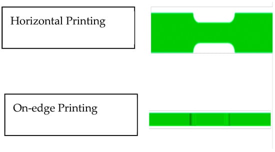
Figure 2.
Orientation of the printed samples relative to the print bed.

Figure 3.
Machining paths at 0°, 90°, and 180° relative to filament layup during micromilling.
Table 2 summarizes key process parameters: layer thickness, raster angle, fabrication direction, and cutting angle (Angle Cut), systematically varied to capture their influence on post-machined surface roughness. To perform the roughness test, Mitutoyo Surftest/Portable Surface Roughness tester was used according to ISO 4287:1997 standard [56].
Table 2.
Experimental matrix and surface roughness results for BASF Ultrafuse 316L.
- Layer Thickness (Input 1: LT): Vertical resolution and interlayer bonding. Thinner layers (≤0.10 mm) improve surface smoothness and density uniformity; thicker layers (0.15–0.20 mm) increase staircase effects. Reducing layer thickness enhances sintered density and machinability [1,2,3,7,8,9,14,15].
- Raster Angle (Input 2: RA): Defines filament orientation in each layer. Governs directional porosity and anisotropy; influences density uniformity and surface texture [1,2,8,9].
- Fabrication Direction (Input 3: FD): Macro-build orientation relative to the print bed. Affects grain alignment, porosity distribution, and residual stresses after sintering. Vertically fabricated parts tend to have higher Ra due to perpendicular layer-step ridges; creating a staircase effect that inherently increases the pre-machined surface roughness. In the correlation analysis, part orientation typically emerges as a significant factor affecting final roughness values. Horizontally fabricated parts present smoother surfaces before machining because layer deposition results in minimal visible staircase effects [8,9,17].
- Angle Cut (Input 4: AC): Tool-feed angle during micromilling (0°, 90°, 180°). Determines anisotropic machining response due to print-induced texture and porosity gradients; influences chip formation and surface morphology.
- Output Variables: Ra (0°), Ra (90°), and Ra (180°) measured with a Mitutoyo SJ-410 profilometer; maximum Ra was used as the overall surface-quality index (Raoverall), capturing combined additive–subtractive effects.
This design captures anisotropic effects from filament layup and gravity-driven sintering shrinkage [3,8,9]. Factorial studies are essential to isolate raster and fabrication direction effects in FFF 316L mechanical and surface behavior [2,3,8,9].
Complementary ASTM E8 tensile bars were fabricated to obtain UTS and elongation. These results were correlated with surface roughness to establish relationships between microstructural consolidation and post-machining quality [24,25,27].
2.4. Post-Processing and Micromilling Procedure
After sintering, all specimens were subjected to micromilling on a precision CNC machine equipped with a two-flute tungsten-carbide end mill (Ø 1.6 mm, 30° helix). Process parameters, including spindle speed = 2000 rpm, feed = 152.4 mm min−1, and depth of cut = 0.20 mm, were selected to achieve stable chip formation without tool chatter.
Three cutting orientations (0°, 90°, 180°) relative to the printed filament path were tested. This approach exposes the anisotropic response of sintered FFF 316L surfaces to mechanical finishing, an effect reported previously in hybrid AM studies [17,18,21,24]. Matras [16] and Greco et al. [15] observed that directional machining of additively manufactured metals leads to alternating chip segmentation due to the layer-wise microstructure. Thus, evaluating multi-directional micromilling provides insight into the interlayer mechanical heterogeneity.
Dry machining conditions were used to prevent coolant contamination and avoid oxidation of freshly cut surfaces [25]. Tool wear was negligible owing to the shallow engagement depth and ductility of sintered 316L [19,51,55].
2.5. Density and Mechanical Testing
Densities of sintered samples were determined via the Archimedes principle using a Torbal AGCN220 analytical balance (±0.0001 g) and ASTM B962 guidelines. The apparent density (ρa) was computed as
Mechanical testing followed ASTM E8 standards using an ADMET universal testing machine. UTS and elongation at break were calculated from stress–strain curves averaged across three replicates. Comparable tensile testing setups have been used to validate metal FFF process integrity [2,7,13].
Correlation of density and tensile strength with surface roughness supports the hypothesis that improved interlayer bonding and reduced porosity lead to smoother machined surfaces [7,8,27].
2.6. Surface Roughness Measurement and Characterization
Post-machining surfaces were characterized using a Mitutoyo Surftest/Portable Surface Roughness tester. Three measurements were taken in each of the 0°, 90°, and 180° directions relative to the cutting path. The mean Ra was recorded for each sample.
This technique provides reliable quantification for metallic FFF materials, where optical systems can be affected by surface reflectivity and porosity [20,22]. Studies such as those by Machno and Zębala [18] and Greco et al. [15] emphasize the necessity of multi-directional roughness analysis to capture the anisotropy inherent to layer-based manufacturing.
2.7. Data Analysis and Statistical Evaluation
All experimental data were analyzed using MATLAB R2016a.
2.7.1. Analysis of Variance (ANOVA)
A full-factorial ANOVA was performed to determine the statistical significance (p < 0.05) of layer thickness, raster angle, and build orientation on Ra. Interaction effects (e.g., layer × orientation) were examined to assess anisotropic behavior. Similar analyses have been applied by Rajhi et al. [35] and Mishra et al. [42] to quantify the influence of FDM parameters on mechanical performance.
2.7.2. Correlation Analysis
Pearson correlation coefficients were computed to explore relationships among Ra, density, and UTS. These methods follow best practices established by Tran and Phan [33] and Elkaseer et al. [44] for identifying preliminary process–response linkages in additive-manufacturing datasets.
2.7.3. Regression Modeling
A multiple linear regression model was developed:
where A = layer thickness, B = raster angle, C = build orientation, and D = cut angle. Model validation included R2, adjusted R2, and RMSE values. Regression approaches similar to those of Abdulshahed and Wafa [54] and Cicek and Johnson [55] were employed to ensure robustness before extending to nonlinear ML frameworks.
2.7.4. Data Readiness for AI Modeling
The data were benchmarked against machine-learning implementations (ANN, RFR, SVM) as recommended in recent AM literature [45,47,48,54]. Batu et al. [47] and Natesh et al. [48] demonstrated that adequate dataset volume and variance are critical for achieving predictive R2 > 0.9 in roughness prediction. Although the current dataset (n = 34) supports linear modeling, future expansion will enable training of advanced algorithms for hybrid AM optimization [47,55].
2.8. Experimental Factors Summary
Table 3 summarizes the key experimental factors affecting surface roughness in hybrid FFF–micromilling of 316L stainless steel. Additive parameters: layer thickness (LT), raster angle (RA), and fabrication direction (FD), capture geometric resolution, filament-induced anisotropy, and gravitational densification, while the subtractive factor, micromilling direction (AC), evaluates directional machinability. Material properties (density and UTS) provide context for linking part consolidation to surface quality. Together, these factors form a structured framework for analyzing how additive and subtractive variables interact to determine final surface integrity.
Table 3.
Experimental factors.
2.9. Section Summary
This comprehensive methodology integrates metal FFF printing, sintering, micromilling, and multi-directional surface metrology into a unified hybrid-manufacturing framework. Compared with earlier studies [1,2,3,6,14,17,18,21,25], this work uniquely combines statistical correlation, ANOVA, and regression modeling across both additive and subtractive domains, providing a reproducible experimental foundation for future AI-based surface roughness prediction in metallic FDM/FFF parts.
3. Results and Discussion
3.1. Effect of Process Parameters on Surface Roughness
Correlation and regression analyses revealed distinct relationships among the four primary process parameters; layer thickness, raster angle, fabrication direction, and cutting angle, and their combined influence on the overall surface roughness (Raoverall) of sintered and micromilled 316L stainless steel parts fabricated by FDM/FFF. Figure 4, Figure 5, Figure 6 and Figure 7 summarize these relationships, where each input parameter is plotted against the corresponding Raoverall response.
3.1.1. Layer Thickness
As shown in Figure 4, a moderate positive correlation exists between layer thickness and overall surface roughness (r = 0.326, p = 0.060). The blue dots represent individual experimental measurements of for specimens printed at either 0.10 mm or 0.20 mm layer thickness, illustrating the variability in post-machining surface finish. The red line is the linear regression trend line, which indicates the overall increasing tendency of surface roughness with thicker layers. Specimens printed with a finer 0.10 mm layer thickness consistently produced smoother surfaces compared with those printed at 0.20 mm. The gradual increase in Raoverall for thicker layers can be attributed to pronounced staircase effects, reduced interlayer diffusion, and nonuniform shrinkage during the debinding–sintering process, which collectively result in residual porosity and uneven grain boundaries on the machined surface.
These findings align with the observations of Boschetto et al. [1] and Galati and Minetola [5], who reported that thinner layers minimize surface asperities and improve isotropy in sintered 316L parts. Moreover, fine-layer fabrication enhances thermal uniformity and inter-filament bonding strength, leading to higher density and improved machinability, as also confirmed by Liu et al. [6] and Martignoni et al. [7]. On the other hand, fine-layer fabrication brings several limitations alongside, such as a longer printing time, higher risk of printing defects due to variations in filament flow or thermal fluctuations, as well as a higher risk of thermal accumulation. The moderate scatter in the 0.20 mm data suggests interaction effects between layer thickness and other process parameters, particularly build orientation and raster angle. Overall, the results confirm that accurate control of vertical resolution in the FFF process is a key strategy for improving surface integrity and achieving consistent post-machined quality in hybrid additively manufactured metallic components.

Figure 4.
Effect of layer thickness on overall surface roughness of micromilled FFF 316L specimens.
3.1.2. Cutting Direction (Angle Cut)
The strongest and most statistically significant correlation was found between cutting angle and surface roughness, with r = 0.486 and p = 0.004 (Figure 5). In this figure, the blue dots represent the individual experimental measurements of maximum surface roughness obtained at each cutting angle, illustrating the spread and variability in the dataset. The red line represents the linear regression trend line, which highlights the overall increasing tendency of surface roughness as the cutting angle becomes more misaligned with the filament raster direction. This relationship indicates that the toolpath orientation relative to the filament raster direction plays a dominant role in controlling chip segmentation and plowing dynamics during micromilling. Cutting parallel or near parallel to the primary raster direction minimizes force fluctuations and surface tearing, resulting in smoother surface finishes.
Comparable findings were reported by Greco et al. [15] for micromilling of SLM-produced AISI 316L and by He et al. [17] for additively manufactured Al–Si–Mg alloys, both showing that machining along the principal layer or melt-pool direction reduces the Ra and burr formation. The results here further confirm that optimizing the cutting angle relative to the internal filament orientation can substantially improve the micromachined surface quality of sintered FFF parts. The root cause of this phenomenon can be related to the anisotropy introduced during filament deposition, which results in direction-dependent variations in hardness, density, and chip formation behavior during consequent micromilling. Keeping in mind the scale of the micromilling process, the cutting angle influences how the micro tool interacts with microstructural patterns resulting from the printing and sintering stages. Encountering residual pores and voids during micro milling can disrupt chip flow and cause localized tool vibration, conversely, affecting the final surface integrity and roughness.

Figure 5.
Influence of cutting direction (Angle Cut) on surface roughness and texture uniformity.
3.1.3. Fabrication Direction
As illustrated in Figure 6, the fabrication direction (coded as horizontal = 1, vertical = 0) exhibited a negligible correlation with overall surface roughness (r = 0.013, p = 0.942). In this figure, the blue dots represent individual roughness measurements for specimens built in either orientation, showing the distribution and overlap of values between the two groups (horizontal = 1, vertical = 0). The red line represents the linear regression fit, which is nearly flat, confirming the absence of a meaningful trend between fabrication direction and surface roughness. This result indicates that within the tested range, the build orientation had no statistically significant influence on the post-machined surface quality of sintered FFF 316L parts. Both horizontally and vertically built specimens achieved comparable Raoverall values after micromilling, suggesting that the sintering and material removal processes effectively mitigated geometric anisotropies typically associated with layer stacking.
Previous studies have shown that fabrication direction often affects surface morphology and mechanical properties due to differing layer interfaces and stress distributions [12,17,28]. However, in this study, the combination of debinding/sintering and uniform material removal during micromilling likely minimized these directional effects. Similar neutral behavior was observed by Matras [16] and He et al. [17], who reported that finishing operations such as milling and polishing can homogenize the surface texture generated during additive deposition. The nearly flat regression line in Figure 7 supports the conclusion that, for FFF metal components subjected to precision micromilling, the initial build orientation has a minimal effect on the final surface roughness when the process is properly controlled.

Figure 6.
Variation of surface roughness with fabrication direction for sintered FFF 316L parts.
3.1.4. Raster Angle
As shown in Figure 7, the raster angle exhibited a weak negative correlation with overall surface roughness (r = –0.130, p = 0.466), indicating that the effect of raster orientation on Raoverall is statistically insignificant. In this figure, the blue dots represent individual experimental measurements of maximum surface roughness across the three tested raster orientations (0°, 30°, 45°), illustrating the variability within each group. The red line denotes the linear regression trend, which has a slight downward slope, consistent with the weak negative correlation but demonstrating no meaningful predictive relationship. This suggests that within the investigated range, the raster angle alone does not substantially influence surface finish once the part undergoes sintering and precision micromachining.
Subtle variations in texture observed across different raster orientations could stem from localized differences in filament overlap and bonding quality, which affect microstructural uniformity after sintering. These minor effects, while not statistically significant, may still contribute to second-order interactions with layer thickness or cutting direction. The overall results imply that the raster angle’s influence on the micromilled surface finish is secondary compared with layer thickness and cutting angle.

Figure 7.
Effect of raster angle on the post-machined surface roughness of FFF 316L specimens.
3.2. Regression Modeling and Quantitative Interpretation
A multiple linear regression model was applied to quantify the combined influence of the four process parameters—layer thickness, raster angle, fabrication direction, and micromilling direction (Angle Cut)—on the overall surface roughness. The resulting model achieved R2 = 0.335 with a statistical significance of p = 0.0158, indicating that approximately one-third of the variability in Ra is explained by the selected process variables.
As summarized in Table 4, among all predictors, the micromilling direction (Angle Cut) emerged as the dominant contributor to surface roughness, exhibiting the strongest and most statistically significant correlation (r = 0.486, p = 0.004). Layer thickness showed a moderate positive correlation with near-boundary statistical significance (r = 0.326, p = 0.060), indicating that thicker deposited layers tend to increase post-machining roughness due to enhanced stair-stepping effects. In contrast, raster angle (r = −0.130, p = 0.466) and fabrication direction (r = 0.013, p = 0.942) demonstrated a negligible and statistically insignificant influence on the final surface roughness after sintering and micromilling.
Table 4.
Correlation values of the study for the variation analysis.
Figure 8, Figure 9 and Figure 10 present three-dimensional directional roughness maps for cutting angles of 0°, 30°, and 45°, respectively. At AC = 0°, the roughness distribution remains relatively compact, indicating more uniform shearing across the filament–matrix interfaces. As the cutting angle increases to 30° and 45°, the roughness envelope expands significantly, revealing stronger anisotropic behavior and an increased sensitivity of Ra to the probe direction. The highest dispersion and peak roughness values observed at AC = 45° confirm that cutting orientation is the dominant factor governing surface integrity in hybrid FFF–micromilling, consistent with the statistical trends reported in Table 4.
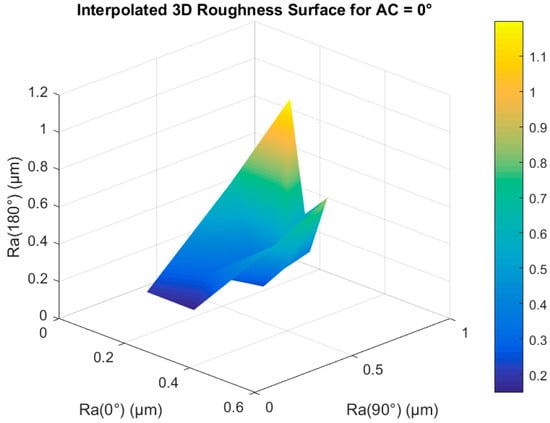
Figure 8.
Three-dimensional anisotropy map of surface roughness for AC = 0°.

Figure 9.
Three-dimensional anisotropy map of surface roughness for AC = 30°.
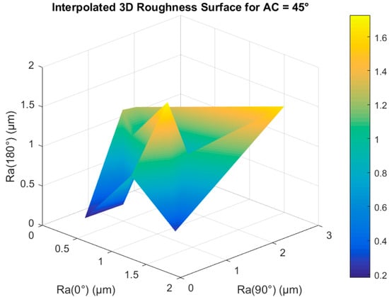
Figure 10.
Three-dimensional anisotropy map of surface roughness for AC = 45°.
These findings confirm that hybrid-manufactured surfaces are governed primarily by the cutting orientation relative to FFF-deposited material flow lines, which dictates the ease of shearing across filament interfaces. Similar observations were reported by Matras [16] and Machno et al. [18] for SLM-fabricated and cast AISI 316L machining, where tool direction exerted the strongest influence on surface roughness and burr formation.
Based on these results, several practical implications can be derived for the design and optimization of hybrid FFF–micromilling processes across aerospace, biomedical, and microfluidic/MEMS applications. Function-critical, load-bearing, and flow-governing surfaces should be oriented during printing such that they are aligned as closely as possible with the primary filament deposition direction, thereby reducing anisotropic cutting resistance, minimizing surface tearing during micromilling, and improving fatigue- and flow-sensitive surface quality. An appropriate machining allowance should be intentionally incorporated into near-net-shape additive designs to compensate for printing- and sintering-induced surface irregularities and to ensure that tight dimensional and surface-quality requirements are achieved after finishing. Micromilling toolpaths should be preferentially defined parallel or near-parallel to the filament flow direction to promote stable chip formation, suppress burr formation, enhance tribological behavior, and improve the consistency of the machined surface finish. The strong sensitivity of surface roughness to cutting orientation further indicates that hybrid process planning should adopt a fully integrated additive–subtractive co-optimization strategy, which is essential for achieving predictable aerodynamic performance in aerospace micro-components, long-term reliability and biocompatibility in biomedical devices, and stable flow characteristics in microfluidic and MEMS systems.
3.3. Comparative Analysis with Literature
The observed dependence hierarchy, Angle Cut > Layer Thickness > Raster Angle ≈ Fabrication Direction, is consistent with trends reported in prior hybrid AM–machining and metal FFF studies. Greco et al. [15] demonstrated that the layer-wise microstructure inherent in additively manufactured AISI 316L leads to anisotropic cutting resistance during micromilling, significantly affecting chip segmentation and the surface finish. Similarly, Sadaf et al. [12] showed that FFF-produced 316L parts retain porosity-induced microstructural heterogeneity after sintering, which directly influences tool–workpiece friction and machined surface morphology. Comparable anisotropic machining effects were also reported by Matras [16] and Machno and Zębala [18] for SLM-fabricated 316L, where the directional dependence of surface roughness and burr formation was attributed to layer-induced microstructural features.
However, it is important to emphasize that most existing machining studies on additively manufactured 316L are based on laser-based processes such as SLM and LPBF, where anisotropy originates primarily from melt-pool solidification patterns and thermal gradients [15,16,17,18]. In contrast, metal FFF produces a fundamentally different anisotropic microstructure, governed by filament stacking, interlayer diffusion, and binder-assisted powder consolidation. The present results demonstrate that, despite these fundamental process differences, extrusion-induced anisotropy in metal FFF also persists after full debinding and sintering and continues to govern micromilling behavior, which has not been quantitatively demonstrated in prior FFF-based hybrid studies.
Moreover, while several FFF investigations reported the influence of printing parameters on as-printed or as-sintered surface roughness [9,12,21], and separate machining studies focused on post-processing of laser-based AM parts [15,16,17,18], there remains a clear gap in the literature regarding statistically unified additive–subtractive analysis for sintered metal FFF components. The present study directly addresses this gap by coupling layer thickness, raster angle, fabrication direction, and cutting direction within a single experimental–statistical framework.
The moderate regression coefficient obtained in this work (R2 = 0.335) further indicates the presence of nonlinear and coupled interactions among process parameters, which cannot be fully captured by linear models alone. This observation is consistent with recent reports on nonlinear surface-quality prediction using ANN-, RFR-, and SVR-based approaches in both additive and hybrid manufacturing systems [45,47,48,54]. These data-driven methods have been shown to significantly outperform conventional regression models by capturing multivariate coupling between deposition behavior, material consolidation, and machining dynamics.
Regarding novelty and suitability, while previous studies independently examined (i) FFF process parameters and densification behavior [9,12,21], or (ii) micromilling responses of laser-based AM metals [15,16,17,18], the present manuscript is, to the authors’ knowledge, the first to statistically unify metal FFF printing parameters, sintering effects, and micromilling direction within a single validated correlation–regression framework for 316L stainless steel. By quantitatively demonstrating that extrusion-induced anisotropy governs post-micromilling surface quality even after full densification, this work advances hybrid additive–subtractive manufacturing knowledge beyond existing single-stage investigations and provides a direct foundation for data-driven and intelligent hybrid process optimization.
3.4. Implications for Hybrid Process Optimization
The correlation and regression results jointly indicate that minimizing surface roughness in hybrid FDM–micromilling systems can be effectively achieved through the following:
- (i)
- Fine-layer deposition (<0.1 mm) and
- (ii)
- Toolpath alignment with filament orientation during cutting.
These strategies enable achieving Ra < 1.2 µm without extensive post-polishing. The results further highlight the potential of integrating statistical modeling with machine-learning–based predictive control systems to optimize hybrid metal FFF workflows [32,45,47,48,54].
This approach supports the development of intelligent hybrid additive–subtractive manufacturing frameworks, wherein data from the additive stage inform adaptive finishing strategies, ultimately reducing surface defects, energy consumption, and tool wear.
4. Conclusions
This study provides a comprehensive statistical evaluation of the relationship between additive manufacturing parameters and post-machining surface roughness in hybrid FDM–FFF fabricated 316L stainless steel components. Using correlation and multiple regression analyses on 34 experimental datasets, the research offers new insights into how additive and subtractive parameters interact to influence final surface integrity after micromilling.
The following key conclusions can be drawn:
- Layer thickness exhibited a moderate positive correlation with surface roughness (r = 0.326, p = 0.060), indicating that thicker layers tend to produce rougher post-machined surfaces due to increased staircase effects and nonuniform interlayer bonding. Finer layers enhance chip stability and microstructural uniformity during finishing, consistent with observations by Boschetto et al. [1] and Caminero et al. [2].
- Cutting direction (angle cut) was identified as the dominant factor, showing a strong correlation with roughness (r = 0.486, p = 0.004). Machining parallel to the filament deposition path yielded the smoothest surfaces, validating the anisotropic cutting behavior observed in micromilling studies of AM metals [17,19].
- Fabrication direction and raster angle demonstrated a weak statistical influence on surface roughness (r = 0.013, p = 0.942 and r = –0.130, p = 0.466, respectively). Their limited contribution suggests that sintering effectively homogenizes internal porosity, making machining orientation the dominant factor governing surface response. Similar behavior was reported by O’Connor et al. [9] and Kurose et al. [21].
- The multiple linear regression model achieved R2 = 0.335 (p = 0.0158), confirming that approximately one-third of the surface roughness variation can be captured by the linear effects of process parameters. The remaining variance reflects the nonlinear and thermomechanical interactions characteristic of hybrid AM–machining systems, consistent with the findings in [45,47,48,54].
- The study provides a quantitative framework for optimizing hybrid FDM–micromilling processes. Fine-layer deposition combined with directionally aligned cutting can reduce the Ra below 1.2 µm without secondary polishing. Incorporating data-driven monitoring and machine-learning-based prediction can further improve adaptive control, surface consistency, and process repeatability.
In agreement with the general consensus reported in prior hybrid additively manufactured metal finishing studies, the present work confirms that toolpath orientation relative to the additively induced microstructure is the primary governing factor for post-machining surface roughness. Previous investigations on micromilling and finish machining of additively manufactured 316L and similar alloys consistently report that machining parallel to the layer or melt-pool direction minimizes cutting force fluctuations and surface tearing, resulting in improved Ra values. The present experimental and statistical findings quantitatively reinforce this widely accepted proposal and further demonstrate that this behavior persists in metal FFF components after full debinding and sintering, thereby extending the general principle of anisotropic machinability to hybrid FFF–micromilling processes.
4.1. Practical Applications of Study
The results of this study can be directly applied to functional micro-scale engineering applications such as lab-on-a-chip (LOC) and micro-electro-mechanical systems (MEMS), where fluid flow characteristics, fatigue resistance, and functional reliability are strongly governed by surface integrity, including surface roughness and microstructure. The demonstrated influence of fine-layer deposition and directionally aligned micromilling in achieving Ra values below 1.2 µm provides practical design and process guidelines for manufacturing high-precision micro-components with predictable surface performance. The findings are also highly relevant to the manufacturing of biomedical micro-devices, micro-heat exchangers, and aerospace micro-mechanical components produced through hybrid metal FFF–machining routes, where the surface finish directly affects tribological behavior, heat transfer efficiency, corrosion resistance, and structural durability. The proposed hybrid process-planning strategy therefore enables improved quality control and performance optimization across a wide range of advanced engineering applications.
4.2. Limitations and Outlook for Future Work
Despite the comprehensive experimental and statistical framework presented in this study, several limitations should be acknowledged. First, the investigation is restricted to BASF Ultrafuse 316L stainless steel, and therefore the direct transferability of the results to other metal FFF materials (e.g., 17-4PH, Ti-6Al-4V, copper-based filaments) remains limited. Material-specific differences in powder packing density, binder removal kinetics, sintering shrinkage, and the final microstructure may lead to different anisotropic machining responses and surface roughness trends.
Second, the experimental campaign was conducted on simple prismatic- and tensile-type geometries. While this allows for controlled statistical interpretation, complex three-dimensional components with curved surfaces, internal channels, or lattice structures may exhibit different orientation-dependent surface integrity behaviors due to localized thermal gradients, gravity-driven densification, and tool accessibility constraints. Future work should therefore extend the methodology to parts with greater geometric complexity.
Third, the micromilling parameters were intentionally limited to a single tool geometry and a narrow range of cutting conditions in order to isolate the effect of cutting direction. Although this improves statistical clarity, it limits the ability to resolve higher-order interaction effects. Expanded studies incorporating variables such as spindle speed, feed per tooth, depth of cut, tool coating, and tool wear progression would provide a more complete understanding of hybrid FFF–micromachining behavior.
Additionally, although correlation, ANOVA, and regression analyses adequately quantified the main effects of process parameters, the relatively limited dataset (n = 34) constrained the statistical robustness of higher-order interaction analysis. While main-effect and interaction plots are valuable for visualizing coupled parameter behavior, their construction under the current data density would risk over-interpretation. Future work will therefore employ enlarged full-factorial or response-surface experimental designs to enable statistically reliable interaction plotting and nonlinear modeling.
Mechanical tests were not performed because this study focused exclusively on surface roughness as the primary surface-integrity indicator in hybrid FFF–micromilling of 316L stainless steel.
Finally, the present study focuses primarily on surface roughness (Ra) as the key surface-quality indicator. However, surface integrity is a multi-scale phenomenon that also includes residual stress, microhardness, subsurface deformation, grain refinement, and fatigue performance. These parameters are especially critical for functional applications such as microfluidic devices, MEMS components, and fatigue-sensitive aerospace or biomedical parts. Future investigations will therefore integrate microhardness mapping, X-ray diffraction-based residual stress measurements, and fatigue testing to establish deeper links between fine-layer deposition, micromilling behavior, and long-term structural durability.
From a broader perspective, future research will also focus on machine-learning-assisted prediction of full surface integrity, multi-objective optimization of additive–subtractive workflows, and real-time hybrid process monitoring. These developments will ultimately support intelligent, closed-loop manufacturing of metal FFF components with deterministic surface quality and performance.
4.3. Novel Contributions
The novelty of this research lies in its systematic linkage of additive parameters (layer thickness, raster angle, fabrication direction) with subtractive machining variables (Angle Cut) using experimental correlation and regression models applied to sintered metal FFF specimens. While previous studies investigated these domains separately, this work establishes a unified analytical framework that bridges additive and subtractive interactions for 316L stainless steel, paving the way for predictive hybrid manufacturing optimization.
Author Contributions
Conceptualization, A.D. and S.O.; methodology, A.D. and S.O.; software, A.D.; validation, A.D., A.M. and M.O.; formal analysis, A.D. and S.O.; investigation, S.O. and M.O.; resources, A.M. and K.N.; data curation, S.O.; writing—original draft preparation, A.D. and S.O.; writing—review and editing, A.D., S.O., A.M., M.O. and K.N.; visualization, S.O. and K.N.; supervision, A.D. and S.O.; project administration, S.O. and A.D.; funding acquisition, M.O., K.N. and A.M. All authors have read and agreed to the published version of the manuscript.
Funding
This research did not receive any specific grant from funding agencies in the public, commercial, or not-for-profit sectors. The prototyping and publication costs were supported by the authors’ affiliated institutions (SHSU and AUM).
Data Availability Statement
The data presented in this study may be available on request from the corresponding author.
Acknowledgments
The authors acknowledge the support of Sam Houston State University and American University of the Middle East colleagues who provided valuable input.
Conflicts of Interest
The authors declare no conflicts of interest.
Abbreviations
The following abbreviations are used in this manuscript:
| AM | Additive Manufacturing |
| FFF | Fused Filament Fabrication |
| FDM | Fused Deposition Modeling |
| H-AM | Hybrid Additive–Subtractive Manufacturing |
| SLM | Selective Laser Melting |
| DED | Directed Energy Deposition |
| MIM | Metal Injection Molding |
| SEM | Scanning Electron Microscopy |
| UTS | Ultimate Tensile Strength |
| DOE | Design of Experiments |
| RSM | Response Surface Methodology |
| ANOVA | Analysis of Variance |
| ANN | Artificial Neural Network |
| RFR | Random Forest Regression |
| SVM | Support Vector Machine |
| Ra | Arithmetic Mean Surface Roughness |
| R2 | Coefficient of Determination |
| ρa | Apparent Density |
References
- Boschetto, A.; Bottini, L.; Miani, F.; Veniali, F. Roughness investigation of steel 316L parts fabricated by Metal Fused Filament Fabrication. J. Manuf. Process. 2022, 81, 261–280. [Google Scholar] [CrossRef]
- Caminero, M.A.; Romero, A.; Chacón, J.M.; Núñez, P.J.; García-Plaza, E.; Rodríguez, G.P. Additive manufacturing of 316L stainless-steel structures using fused filament fabrication technology. Rapid Prototyp. J. 2021, 27, 583–591. [Google Scholar] [CrossRef]
- Cerlincă, D.-A.; Tamașag, I.; Beșliu-Băncescu, I.; Severin, T.-L.; Dulucheanu, C. Experimental investigation of FDM manufacturing of 316L stainless steel. Int. J. Adv. Manuf. Technol. 2024, 135, 1449–1463. [Google Scholar] [CrossRef]
- Kedziora, S.; Decker, T.; Museyibov, E.; Morbach, J.; Hohmann, S.; Huwer, A.; Wahl, M. Strength properties of 316L and 17-4 PH stainless steel produced with additive manufacturing. Materials 2022, 15, 6278. [Google Scholar] [CrossRef]
- Galati, M.; Minetola, P. Analysis of density, roughness, and accuracy of the ADAM (metal FFF) process for metal parts. Materials 2019, 12, 4122. [Google Scholar] [CrossRef]
- Liu, B.; Wang, Y.; Lin, Z.; Zhang, T. Creating metal parts by fused deposition modeling and sintering. Mater. Lett. 2020, 263, 127252. [Google Scholar] [CrossRef]
- Martignoni, L.; Vegro, A.; Candidori, S.; Shaikh, M.Q.; Atre, S.V.; Graziosi, S.; Casati, R. Prototyping and characterisation of 316L stainless steel parts and lattice structures printed via metal fused filament fabrication. Rapid Prototyp. J. 2024, 30, 123–141. [Google Scholar] [CrossRef]
- Obeidat, S.; Basith, I.; Dakeev, U. The impact of printing direction and raster angle on apparent density and mechanical properties of 316L stainless steel parts printed by FDM/FFF technology. Int. J. Mod. Eng. 2024, 24, 29–35. [Google Scholar] [CrossRef]
- O’Connor, H.; Singh, G.; Kumar, A.; Paetzold, R.; Celikin, M.; O’Cearbhaill, E.D. Fused filament fabrication using stainless steel 316L–polymer blend: Analysis and optimization for green density and surface roughness. Polym. Compos. 2024, 45, 10632–10644. [Google Scholar] [CrossRef]
- Ren, L.; Zhou, X.; Song, Z.; Zhao, C.; Liu, Q.; Xue, J.; Li, X. Process parameter optimization of extrusion-based 3D metal printing utilizing PW–LDPE–SA binder system. Materials 2017, 10, 305. [Google Scholar] [CrossRef] [PubMed]
- Spiller, S.; Kolstad, S.O.; Razavi, N. Fabrication and characterization of 316L stainless steel components printed with material extrusion additive manufacturing. Procedia Struct. Integr. 2023, 42, 1239–1248. [Google Scholar] [CrossRef]
- Sadaf, M.; Bragaglia, M.; Nanni, F. A simple route for additive manufacturing of 316L stainless steel via fused filament fabrication. J. Manuf. Process. 2021, 67, 141–150. [Google Scholar] [CrossRef]
- Wagner, M.A.; Engel, J.; Hadian, A.; Clemens, F.; Rodríguez-Arbaizar, M.; Carreño-Morelli, E.; Wheeler, J.M.; Spolenak, R. Filament extrusion-based additive manufacturing of 316L stainless steel: Effects of sintering conditions. Addit. Manuf. 2022, 59, 103147. [Google Scholar] [CrossRef]
- Kaynak, Y.; Kitay, O. Porosity, surface quality, microhardness and microstructure of SLM 316L after finish machining. J. Manuf. Mater. Process. 2018, 2, 36. [Google Scholar] [CrossRef]
- Greco, S.; Kieren-Ehses, S.; Kirsch, B.; Aurich, J.C. Micro milling of additively manufactured AISI 316L: Impact of layerwise microstructure. Int. J. Adv. Manuf. Technol. 2021, 112, 361–373. [Google Scholar] [CrossRef]
- Matras, A. Research and optimization of surface roughness in milling of SLM semi-finished parts. Materials 2020, 13, 9. [Google Scholar] [CrossRef]
- He, Q.; Kang, X.; Wu, X. Micro-milling of additively manufactured Al–Si–Mg alloys. Materials 2024, 17, 2668. [Google Scholar] [CrossRef]
- Machno, M.; Zębala, W. Comparative study of the dimensional and shape accuracy of 316L manufactured using SLM and casting after milling and WEDM. Materials 2024, 17, 2907. [Google Scholar] [CrossRef] [PubMed]
- Montalti, A.; Galiè, G.; Pignatelli, E.; Liverani, A. Enhancing surface roughness of material extrusion AM components via innovative ironing process. Virtual Phys. Prototyp. 2024, 19, e2401929. [Google Scholar] [CrossRef]
- Salvi, D.; Ucciardello, N.; Vesco, S. Multi-Head MEX 3D Printing of Self-Recoverable Joule-Heating-Based Shape Memory Polymeric Components. Arab. J. Sci. Eng. 2025. [Google Scholar] [CrossRef]
- Kurose, T.; Abe, Y.; Santos, M.V.A.; Kanaya, Y.; Ishigami, A.; Tanaka, S.; Ito, H. Influence of layer directions on properties of 316L parts fabricated through fused deposition of metals. Materials 2020, 13, 2493. [Google Scholar] [CrossRef]
- Quarto, M.; Carminati, M.; D’Urso, G. Density and shrinkage evaluation of AISI 316L parts printed via FDM process. Mater. Manuf. Process. 2021, 36, 1535–1543. [Google Scholar] [CrossRef]
- Vesco, S.; Salvi, D. Fuzzy skin in fused filament fabrication: Enhancing morphology, wettability, and friction through a full-factorial experimental plan. Prog. Addit. Manuf. 2025, 10, 11233–11257. [Google Scholar] [CrossRef]
- Gorey, T.J.; Stull, J.A.; Hackenberg, R.E.; Clark, C.L.; Hooks, D.E. Enhancing surface finish of AM 316L stainless steel with pulse/pulse reverse electropolishing. J. Miner. 2023, 75, 195–208. [Google Scholar] [CrossRef]
- Behjat, A.; Lannunziata, E.; Gadalińska, E.; Iuliano, L.; Saboori, A. Improving surface quality and mechanical properties of AM AISI 316L by different surface post-treatments. Procedia CIRP 2023, 118, 771–776. [Google Scholar] [CrossRef]
- Chueca de Bruijn, A.; García de la Torre, H.; Gómez-Gras, G.; Pérez-Martínez, M.A. Effect of ball burnishing on fused-filament fabricated parts. Addit. Manuf. 2021, 46, 102133. [Google Scholar] [CrossRef]
- Hassan, W.; Farid, M.A.; Tosi, A.; Rane, K.; Strano, M. Effect of printing parameters on sintered properties of EAM 316L parts. Int. J. Adv. Manuf. Technol. 2021, 114, 3057–3067. [Google Scholar] [CrossRef]
- Zaitceva, M.; Sotov, A.; Popovich, A.; Sufiiarov, V. Stainless steel 316L fabricated by FDM: Microstructure and mechanical properties. J. Manuf. Mater. Process. 2024, 8, 259. [Google Scholar] [CrossRef]
- Soler, D.; Telleria, M.; Belén, M.; Espinosa, E.; Cuesta, M.; Arrazola, P.J. Prediction of surface roughness after finishing processes using ANN. J. Manuf. Mater. Process. 2022, 6, 82. [Google Scholar] [CrossRef]
- Mukherjee, T.; Shen, W.; Liao, Y.; Li, B. Improving deposited surface quality using structured light characterization and modeling. J. Manuf. Mater. Process. 2024, 8, 124. [Google Scholar] [CrossRef]
- Betts, J.L.; Sampson, B.J.; Lindsey, K.; Brinkley, F.M.; Priddy, M.W. Reduction of process-induced porosity for Ultrafuse 316L via parameter optimization. Crystals 2024, 14, 285. [Google Scholar] [CrossRef]
- Suresh, V.; Balasubramaniam, B.; Yeh, L.; Li, B. Recent advances in in situ 3D surface topographical monitoring for AM. J. Manuf. Mater. Process. 2025, 9, 133. [Google Scholar] [CrossRef]
- Tran, N.H.; Phan, N.D.M. Analyzing the Impact of Process Parameters on Surface Roughness and Mechanical Properties in FDM 3D Printing Using Machine Learning. Int. J. Interact. Des. Manuf. 2025, 19, 8709–8728. [Google Scholar] [CrossRef]
- Boschetto, A.; Bottini, L.; Veniali, F. Integration of FDM surface quality modeling with process design. Addit. Manuf. 2016, 12, 334–344. [Google Scholar] [CrossRef]
- Rajhi, W.; Ali, A.B.; Jasim, D.J.; Mehrabi, O.; Ben Said, L.; Moradi, M. Mathematical and statistical analysis of FFF parameters via response surface methodology. Mathematics 2024, 12, 3146. [Google Scholar] [CrossRef]
- Zhang, T.; Yuan, L. Understanding surface roughness on vertical surfaces of 316L in LPBF AM. Powder Technol. 2022, 411, 117957. [Google Scholar] [CrossRef]
- Dias, Y.E.P.; Lima, J.S.D.; Coêlho, G.D.C.; Maciel, T.M.; Neto, J.F.D.S.; Castro, W.B.D. Quality control, monitoring and techniques for surface quality optimization in wire arc additive manufacturing: A review. Rapid Prototyp. J. 2025. ahead-of-print. [Google Scholar] [CrossRef]
- Mushtaq, R.T.; Iqbal, A.; Wang, Y.; Cheok, Q.; Abbas, S. Parametric effects of FFF approach on surface roughness of ABS and Nylon-6. Materials 2022, 15, 5206. [Google Scholar] [CrossRef]
- La Fé-Perdomo, I.; Ramos-Grez, J.A.; Jeria, I.; Guerra, C.; Barrionuevo, G.O. Statistical and ML-based regressors for roughness and properties of SLM 316L. J. Manuf. Process. 2022, 80, 666–682. [Google Scholar] [CrossRef]
- Yang, D.; Tang, J.; Xia, F.; Zhou, W. Rough surface characterization and redundant parameter sets for modeling. Materials 2022, 15, 5971. [Google Scholar] [CrossRef]
- Kim, E.-J.; Lee, C.-M.; Kim, D.-H. Post-processing effects on mechanical characteristics of AM 304L steel. J. Mater. Res. Technol. 2021, 15, 1370–1381. [Google Scholar] [CrossRef]
- Mishra, A.; Kumar, R.; Sharma, A.K.; Gupta, N.K.; Somani, N. Statistical analysis of process parameters for Wood–PLA FDM composites. Int. J. Interact. Des. Manuf. 2024, 18, 1303–1315. [Google Scholar] [CrossRef]
- Kumaresan, R.; Kadirgama, K.; Samykano, M.; Harun, W.S.W.; Thirugnanasambandam, A.; Kanny, K. Optimization of process parameters to enhance strengths of PETG in FDM. J. Mater. Res. Technol. 2025, 37, 397–416. [Google Scholar] [CrossRef]
- Elkaseer, A.; Schneider, S.; Scholz, S.G. Experiment-based process modeling and optimization for resource-efficient FFF. Appl. Sci. 2020, 10, 2899. [Google Scholar] [CrossRef]
- Sharma, A.; Saini, R.S.; Kaushik, A.; Okshah, A.; Kuruniyan, M.S.; Gurumurthy, V.; Vyas, R.; Binduhayyim, R.I.H.; Heboyan, A. ML-based approach for surface roughness prediction in dental prototyping. Sci. Rep. 2025, 15, 32239. [Google Scholar] [CrossRef]
- Chen, H.; Yaseer, A.; Zhang, Y. Top Surface Roughness Modeling for Robotic Wire Arc Additive Manufacturing. J. Manuf. Mater. Process. 2022, 6, 39. [Google Scholar] [CrossRef]
- Batu, T.; Lemu, H.G.; Shimels, H. Application of AI for surface roughness prediction of AM components. Materials 2023, 16, 6266. [Google Scholar] [CrossRef]
- Natesh, C.P.; Siddeshkumar, N.G.; Srinivasa, G.; Shivaramakrishna, A.; Pruthvi, H.M.; Prasad, C.D.; Shashidhara, Y.M.; Amarendra, H.J.; Tiwari, A.; Aden, A.A. Multi-objective optimization of surface roughness and MRR in 316L steel via Taguchi–RSM–ANN–RFR. Sci. Rep. 2025, 15, 36583. [Google Scholar] [CrossRef]
- Adeniji, D.; Schoop, J.; Gunawardena, S.; Hanson, C.; Jahan, M. Characterization and modeling of surface roughness and burr formation in slot milling. J. Manuf. Mater. Process. 2020, 4, 59. [Google Scholar] [CrossRef]
- Khanafer, K.; Cao, J.; Kokash, H. Condition monitoring in additive manufacturing: A critical review. J. Manuf. Mater. Process. 2024, 8, 95. [Google Scholar] [CrossRef]
- Dinc, A.; Mamedov, A. Optimization of surface quality and machining time in micro-milling of glass. Aircr. Eng. Aerosp. Technol. 2022, 94, 676–686. [Google Scholar] [CrossRef]
- Jacob, J.; Pejak Simunec, D.; Kandjani, A.E.; Trinchi, A.; Sola, A. Review of fused filament fabrication of metal parts: Current developments and challenges. Technologies 2024, 12, 267. [Google Scholar] [CrossRef]
- Mamedov, A.; Dinc, A.; Guler, M.A.; Demiral, M.; Otkur, M. Tool wear in micromilling: A review. Int. J. Adv. Manuf. Technol. 2025, 137, 47–65. [Google Scholar] [CrossRef]
- Abdulshahed, A.M.; Wafa, F. Surface Roughness Prediction in Additive Manufacturing: Presenting the Power of Neural Networks Compared to Linear Regression. J. Adv. Manuf. Syst. 2025, 24, 69–88. [Google Scholar] [CrossRef]
- Cicek, U.I.; Johnson, A.A. Multi-objective optimization of FDM process parameters using Taguchi-based gray relational analysis. Int. J. Adv. Manuf. Technol. 2025, 137, 3709–3725. [Google Scholar] [CrossRef]
- ISO 4287:1997; Geometrical Product Specifications (GPS)—Surface Texture: Profile Method—Terms, Definitions and Surface Texture Parameters. International Organization for Standardization: Geneva, Switzerland, 1997.
Disclaimer/Publisher’s Note: The statements, opinions and data contained in all publications are solely those of the individual author(s) and contributor(s) and not of MDPI and/or the editor(s). MDPI and/or the editor(s) disclaim responsibility for any injury to people or property resulting from any ideas, methods, instructions or products referred to in the content. |
© 2025 by the authors. Licensee MDPI, Basel, Switzerland. This article is an open access article distributed under the terms and conditions of the Creative Commons Attribution (CC BY) license (https://creativecommons.org/licenses/by/4.0/).