Abstract
Large cylindrical worm gear set of ISO type I are manufactured using endmill tools on universal CNC machine tools. This manufacturing method requires neither special gear-generating machines nor special tools. The tooth flank forms of ISO type I cylindrical worm gears are involute helicoids as a standard. The targeted theoretical tooth flanks of the worm and the mating worm wheel are determined based on a tooth contact analysis (TCA) of such worm gear set. The cutting conditions of the worm are determined after the offset distance between the worm axis, and the central axis of the endmill tool is calculated. Afterward, the worm is manufactured by controlling only two axes on machine tools using a swarf milling method by use of the side of the endmill tool under the determined conditions. Meanwhile, the targeted theoretical tooth flanks of the mating worm wheel are modeled in 3-dimensional computer-aided design software, and the worm wheel is manufactured by a swarf milling method in a computer-aided manufacturing process. The comparison of experimental and analytical tooth contact patterns indicates almost no difference between the two tooth contact patterns.
1. Introduction
A worm gear set is a type of staggered shaft gear that transmits power and motion between two shafts that are neither intersecting nor parallel and is constituted by a cylindrical or toroidal worm (or worm screw) that meshes with a worm wheel having tooth flanks [1]. These gear sets achieve a high reduction ratio, and therefore a large multiplication of torque can be realized using only one set of mechanical geared members [2,3,4].
Such worm gear sets are usually used in many kinematic systems, including indexing mechanisms in machine tools, indexing heads, rotary tables, car steering gears, worm reducers in positioning systems, ship control systems, and so on [5]. Simon has clarified the characteristics of a new type of cylindrical worm gear drive [6]. Shreehah et al. have proposed modification of the geometry and technology of cylindrical worms [7]. Deng et al. have developed a parametric study of meshing characteristics with respect to different meshing rollers of the anti-backlash double-roller enveloping worm gear [8]. Litvin et al. have developed tooth modification, contact, and stress analyses [9]. Chen et al. have clarified the contact characteristics of recess action worm gear drives with double-depth teeth [10]. Jiaxing et al. have conducted static shear strength calculations of plastic helical gears mating with steel worms [11]. Sohn et al. have discussed geometric interference in cylindrical worm gear drives using oversized hob to cut worm gears [12]. Osakue et al. have conducted design sizing of cylindrical worm gearsets [13]. Shi et al. have conducted a technology and experimental study of unequal pitches meshing between metal worms and plastic helical gears [14]. Liu et al. have proposed a meshing theory of the axial arc tooth profile of cylindrical worm drive [15]. Mu et al. have developed a meshing theory of involute worm drive [16]. Deng et al. have tried high-precision machining of ZC1 worm gear drives with large modulus [17]. Boral et al. have manufactured ZC cylindrical worms [18]. Balajti has determined undercutting avoidance for designing the production technology of worm gear drives with a curved profile [19]. These literatures have contributed to the high precision and high performance of worm gears.
There are many types of tooth flank forms in cylindrical worm gears. The ISO type I worm gears, which have an involute helicoid tooth flank form, are widely applied in industry circles because of their ease of manufacturing on a special hobbing machine. In this case, the worm wheel is principally generated by a hob cutter having the same form as the tooth flank of the mating worm that conjugates at the worm gear tooth flank. However, to ensure a long tool life and smooth power transmission, a cylindrical hob with land edges must be applied.
A worm gear set is usually applied for the outmoded motion and power transmission of pulverized coal mills in thermal power generations, rolling mills of iron manufacturing plants, and industrial machinery with large gears. The application of large worm gear sets has increased in recent years, and their requirement is expected to increase further, owing to the rise in the demand for the renovation of old plants worldwide.
Meanwhile, Sergej et al. have developed a cross-platform CNC kernel for a multi-axis machine tool [20]. Nakamoto et al. have advanced in multi-axis control and multitasking machining [21]. These multi-axis machine tool technologies have been applied to spiral bevel gears with complicated tooth flanks using common endmill tools or disk cutters [22,23,24,25,26,27,28,29,30]. Moreover, the technologies have also been applied to straight bevel gears [31] and skew bevel gears [32]. In addition, the technologies have been applied to spur gears [33,34,35] and double helical gears [36], and so on. Large cylindrical worm gears have also been manufactured by the same approach [37]. The targeted tooth flank forms of large cylindrical worm gear set were of the Niemann type comprised of concave and convex circular arcs.
In this study, both large worm and mating worm wheels of ISO type I are manufactured using endmill tools on universal CNC machine tools, as mentioned above. The tooth flank forms of the worm gears of ISO type I are involute helicoids. This manufacturing process has the following advantages: (i) The modification of the tooth flank is free; (ii) It is also possible to manufacture the basic plane, hole surface, and outside surface of the workpiece; (iii) Only one-time setup is required; and (iv) Special generating machines and special tools are not required.
The required tooth flank geometry of the worm wheel, in addition to that of the worm, is determined on the basis of the TCA results. Next, the cutting conditions of the worm are determined following the calculation of each offset distance between the worm axis and the central axis of the endmill tool. Afterward, considering the determined conditions, the worm is manufactured using a swarf milling method by controlling only two axes and with the side of the endmill tool. Meanwhile, the targeted theoretical tooth flanks of the mating worm wheel are modeled in a 3-dimensional computer-aided design (CAD) program, and the worm wheel is manufactured by a swarf milling method in a computer-aided manufacturing (CAM) process. The experimental and analytical tooth contact patterns are compared, and the two tooth contact patterns are determined to be nearly identical.
2. Tooth Flanks of Worm and Worm Wheel
The tooth flank form of ISO type I cylindrical worm is an involute helicoid generated by a hob cutter. The tooth flank form is deviated from an involute curve in the entry and exit sides, while the tooth flank form in the center of the tooth width of a worm wheel is an involute curve by a hob cutter. An arbitrary point that rotates about the worm axis performs a screw motion. The locus of the point is the screw surface, and it forms the tooth flank of the worm. The locus of the contact lines in meshing between the tooth flanks of the worm and worm wheel forms the tooth flank of the worm wheel.
2.1. Tooth Flank of Worm
The tooth flank of the worm is considered with respect to a rectangular Gaussian coordinate system whose z-axis coincides with the worm axis, as shown in Figure 1. The tooth flank of the worm is generated by a straight line that performs a screw motion. Considering the straight line as a variable position parameter u, as shown in Figure 2, the x, y, and z components of the position vector of the generating line of the tooth flank are represented by A, B, and C in Equation (1):
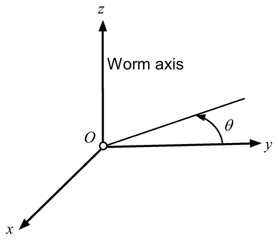
Figure 1.
Coordinate system and worm axis.
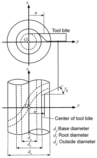
Figure 2.
Parameters expressing tooth flank of worm of ISO Type I.
Considering θ as the angle of rotation of the screw motion of the generating line and a variable parameter, the position vector x of the tooth flank of the worm at the angle θ1 of rotation of the worm may be written as
where i, j, and k are the unit vectors in the directions of x, y, and z axes, respectively. h is the pitch of screw motion and is given by
where Pz is the axial displacement corresponding to one complete revolution. The worm has a right-hand configuration when h is positive and a left-hand configuration when h is negative. Considering the cylindrical worm gear set of ISO type I, A, B, and C in Equation (2) can be represented by
where rg is the cylindrical base radius and γg is the lead angle on the base cylinder. Substituting Equation (4) for Equation (2), the following equations yield:
x, y, and z in Equation (5) express the coordinates of the tooth flank of the ISO type I worm in O-xyz.
2.2. Tooth Flank of Worm Wheel
Figure 3 shows the relation between the worm axis and the axis of the worm wheel in O-xyz. ω1 and ω2 are the angular velocity vectors of the worm and worm wheel, respectively. The z-axis is the worm axis as well as in Figure 1. The perpendicular common with the worm axis and axis of the worm wheel is the y-axis. e means the offset distance between the worm axis and the axis of the worm wheel.
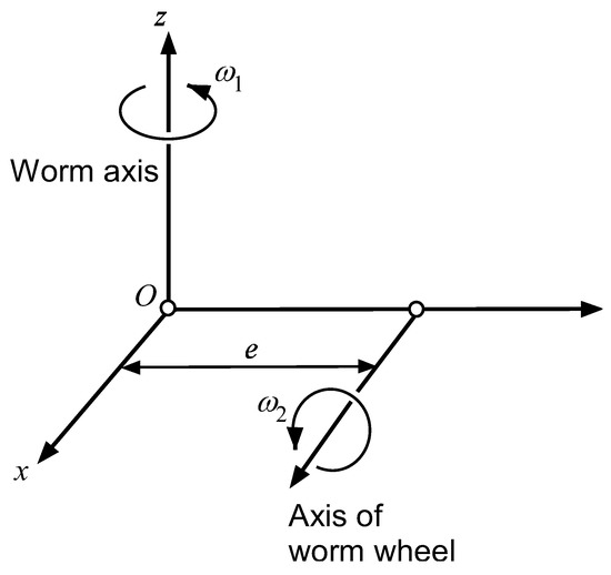
Figure 3.
Relation between worm axis and axis of worm wheel.
The velocity vectors of the worm and worm wheel at the contact point, v1 and v2, respectively, are expressed as follows:
The relative velocity w of the worm wheel with respect to the worm at this point is represented by
where ε is ω1/ω2 = z2/z1.
The worm wheel is principally generated by a tool that has the same form as the tooth flank of the worm without a modified tooth flank. Considering the relative velocity w corresponding to the angle of rotation θ and surface unit normal n of the worm tooth flank, the condition of contact of these two gear tooth flanks is satisfied [38,39]:
n is obtained from
Substituting Equations (7) and (9) in Equation (8), the line of contact between the worm and worm wheel can be represented as a function of θ by Equation (10):
Therefore, the contact line corresponding to the angle of rotation θ in screw motion is
Substituting y and z components in Equation (5) with Equation (10), Equation (12) yields
The contact lines in Equation (11) change with the angle of rotation of the worm θ1, represented by Equation (5). Equation (12) is written as a function of θ when u is given. In this instance, the lines of contact corresponding to the angle of rotation θ1 of the worm can be obtained. Therefore, the contact lines move with the rotation of the worm, and the locus surface x1(u, θ, θ1) can be obtained since θ1 is also a variable parameter.
The worm wheel is rotated by θ1/ε when the worm is rotated by θ1. Therefore, the locus surface x1 is rotated about the x-axis by θ1/ε after x1 moves parallel to the y-axis by −e. The tooth flank of the worm wheel obtained after this may be represented as
where A is the coordinate transform matrix with respect to the rotation about the x-axis and is represented by
The surface unit normal n2 of the tooth flank of the worm wheel is represented by
3. Tooth Contact Analysis of Worm Gear Set
The meshing of the worm and worm wheel is considered in the coordinate system O-xyz as shown in Figure 3. The tooth contact pattern and transmission errors were analyzed without load. Based on the investigation of the experimental tooth contact pattern, the tooth contact pattern moves to the entry side somewhat with the load. Therefore, the tooth contact pattern was determined so that it appears on the exit side somewhat without load, considering the movement of the tooth contact pattern by the load in this study. The method used for the analysis is well-documented in the literature [39]. We recall that the tooth flanks of the worm and worm wheel, and therefore they are in point tangency. This means that two tooth flanks have at a common point the same position vector, and the normal surface vectors are collinear.
Table 1 shows the fundamental specifications of the worm gear set. The number of threads on the worm is 1. The mean diameters of the worm and worm wheel are 260.0 mm and 805.0 mm, respectively. The right side in Figure 4 shows the analytical results of tooth contact pattern, and the left side shows those of transmission errors taking the contact ratio into consideration. When the gap between the tooth flanks of the worm and worm wheel is less than 80 μm, two tooth flanks contact is considered. The tooth contact pattern appears around the midpoint on the tooth flank of the worm wheel. The transmission errors, including the meshing before and after basic meshing, are also shown. The shape of the transmission errors in Figure 4 is parabolic, implying continuous contact along the parabolic path before and after meshing. The gear set with parabolic transmission errors is not sensitive to the misalignment in accordance with the amplitude of the transmission errors. Therefore, the motion and power transmission are smooth even when misalignment exists. The amplitude of transmission errors is approximately 3 arcsec and is very small. The amount of modification of the tooth flanks can control this value.

Table 1.
Fundamental specifications of worm gear set.
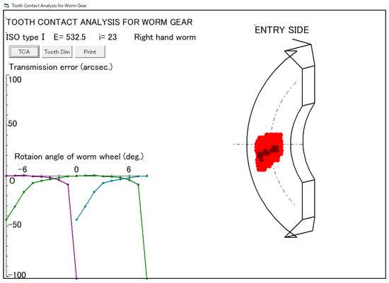
Figure 4.
Analytical tooth contact pattern and transmission errors.
4. Manufacturing of Worm and Worm Wheel
Figure 5 shows the flowchart of the process for TCA and manufacturing of ISO type I worm and worm wheel by end milling on universal CNC machine tools. TCA is done before manufacturing these gears, as indicated in Section 3. When the tooth contact pattern obtained from the analysis is satisfied, the NC data for manufacturing the worm is generated, and it can be manufactured using an endmill tool on a universal CNC machine tool. Meanwhile, the worm wheel is modeled in 3-dimensional CAD software and manufactured using a CAM process using an endmill tool on a universal CNC machine tool. Finally, the experimental tooth contact pattern of the manufactured worm and worm wheel is examined until it matches the theoretical pattern to a satisfactory level.
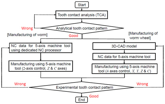
Figure 5.
Process for tooth contact analysis and manufacturing of worm gear set using universal CNC machine tools.
4.1. Manufacturing of Worm
4.1.1. Offset-Cutting Method
An offset-cutting method is used to manufacture the worm. This method does not require a CAD/CAM system. The contact points between the tooth flank of the worm and the side surface of the endmill tool are analyzed, and the corresponding NC data are generated.
A 5-axis controlled intelligent combined machine (Okuma Multus B750) was used for the manufacturing process. This machine has the possibility of some kinds of machining, such as milling and turning. In addition, this machine had five degrees of freedom, namely, linear motion along the x-axis, y-axis, and z-axis, the B-axis that represents the tool inclination, and the C-axis that represents the rotation of the workpiece. For manufacturing the worm, only the motions along the z-axis and C-axis are controlled, and thus, manufacturing of the worm follows a screw-type motion.
Figure 6 shows the offset-cutting method of the right tooth flank of the worm in the x–z cross section. Suppose that the worm tooth flank and endmill tool contact at point Q. In this instance, the position vector expressing the coordinates of the point Q in O-xyz is represented as xr as shown in Equation (5). The distance between the worm axis and the central axis of the endmill tool is defined as the offset distance. The surface unit normal nr of the tooth flank xr intersects the axis of the endmill tool as the swarf milling method utilizes the side of the endmill tool. The y component ny of nr constantly equals zero, as shown in Figure 6, as only the z-axis and C-axis are controlled. In this method, θ is determined for a given value of u since ny is a function of u and θ. The convex and concave of the tooth flank are opposite in comparison with the Niemann profile [37]. x component T of the right side of the tooth space is represented by
where d is the diameter of the endmill tool. nx is the x component of nr. A and B in Equation (16) are expressed as a function of u, and nx is expressed as a function of u and θ. θ is determined from ny = 0 when u is given. Therefore, T is obtained by substituting the determined u and θ for Equation (16). The position vector xcr expressing the coordinates of the rotational center E of the edge of the endmill tool is expressed as:
where nz is the z component of nr.
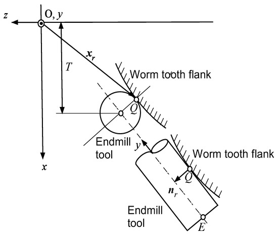
Figure 6.
Offset-cutting method of worm.
Meanwhile, the position vector xcl expressing the coordinates of the rotational center E of the edge of the endmill tool of the left side of the tooth space is expressed as:
where A, B, C, u, θ, h, and θ1 in the right tooth flank are replaced by A’, B’, C’, u’, θ’, h’, and θ1’.
The tooth flank is checked for the penetration of the edge of the endmill tool, and u’ and θ’ that express the left and right tooth flanks are determined. In this instance, the z component of the rotational center of the edge of the endmill tool zcl is compared to that of the right tooth flank. The diameter of the endmill tool is reduced, and the penetration of the tooth flank can be prevented when zcl < zcr is satisfied.
4.1.2. Manufacturing of Worm
The worm was manufactured using some kind of coated carbide endmill tool on the 5-axis controlled combined machine according to the method described in Section 4.1.1 using a dedicated NC processor. The manufacturing of the worm had three stages. The first stage involved a roughing operation, which was carried out using ball endmill tools of diameters of 40 mm, 32 mm, 25 mm, and 16 mm, respectively, before carburizing. The second stage was a semi-finishing operation, and it was carried out twice with an allowance of 0.1 mm via a swarf milling method using radius endmill tools. In this instance, the milling pass was 0.63 mm. The third stage was the finishing operation using the same method but with an allowance of 0.02 mm. In this instance, the milling pass was 0.3 mm. Table 2 shows the cutting conditions for semi-finishing and finishing operations in worm manufacturing. Figure 7 shows the manufacturing of a worm on a universal CNC machine tool. The manufacturing times in semi-finishing and finishing operations were about 820 × 2 min and 1845 min, respectively.
Table 2.
Cutting conditions for semi-finishing and finishing operations in worm manufacturing.
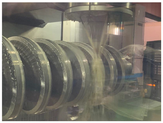
Figure 7.
Manufacturing of worm on universal CNC machine tool.
The manufacturing of the worm was completed successfully without any adverse events.
4.2. Manufacturing of Worm Wheel
4.2.1. CAD/CAM Processes
Numerical coordinates and their surface unit normals for the right and left tooth flanks of the worm wheel were produced on the basis of the TCA results in Figure 4. In the modeling of the tooth flank of the worm wheel, the tooth flank is represented in Equation (13). However, tooth thickness exists between the right and left tooth flanks. The tooth thickness of the worm wheel is determined as follows. The tooth thickness of the hob is also determined when that of the worm is first determined in a special hobbing machine. Afterward, the tooth thickness of the worm wheel without backlash is determined when the worm wheel is generated by a hob cutter that is identical to the tooth flank of the worm. Finally, the tooth thickness of the worm wheel is determined when the backlash is provided. The phases of the coordinates of the right and left tooth flanks were then shifted by one pitch each, and after this process was repeated, the numerical coordinates on the left and right tooth flanks were produced. Once the data of the face and root of the tooth, outer edge, inner edge, and so on are generated, the tooth flank of the worm wheel can be modeled.
Figure 8 shows a 3-dimensional CAD model of the tooth flanks of the worm wheel. The tool interference was checked, an endmill tool was selected, and the cutting conditions for manufacturing the worm wheel were provided. Afterward, the milling pass was calculated automatically. The tooth flank was estimated by smoothing a sequence of the points, removing the non-generated flank, offsetting the radius of the endmill tool, and producing the NURBS surface on the basis of the calculated numerical coordinates. In addition, after the intersection of the curved lines of the right and left tooth flanks was calculated, the sectional curved line was also calculated and approximated to a straight line. Moreover, the approach escape was appended to prevent interference, and NC data and IGES (Initial Graphics Exchange Specification) data for the manufacturing and display were obtained from the attitude of the endmill tool and coordinate transformation. Figure 9 shows the milling passes of the worm wheel through a CAM process. Figure 9a,b corresponds to the milling pass of the right and left tooth flanks, respectively. A swarf milling method based on the calculated milling passes was established. The milling passes were determined so that the surface unit normal of the tooth flank passed through the central axis of the endmill tools.
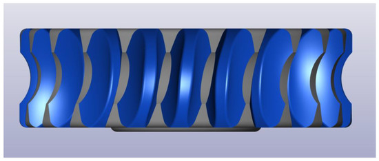
Figure 8.
3-dimensional CAD model of worm wheel.
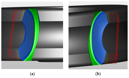
Figure 9.
Milling pass of worm wheel through CAM process. (a) Right tooth flank (b) Left tooth flank.
4.2.2. Manufacturing of Worm Wheel
A 5-axis controlled machining center (DMG MORI Co., Ltd. DMU210P) was used for the manufacturing of the worm wheel. The ball endmill tools were utilized in machining the tooth bottom. The worm wheel material was bronze casting alloy, and it was manufactured using a swarf milling method using an endmill tool and through a CAM process.
The manufacturing process of the worm wheel was also divided into three stages. The first stage was a roughing operation, carried out using ball endmill tools of diameters 40 mm, 25 mm, 16 mm, and 12 mm. The second stage was a semi-finishing operation, performed using a swarf milling method with radius endmill tools, keeping a machining allowance of 0.1 mm. In this instance, the milling pass was 4.8 mm. The third stage was a finishing operation, which was performed using the same method but with a machining allowance of 0.02 mm and a milling pass of 1.0 mm. Table 3 shows the cutting conditions for the semi-finishing and finishing operations of the tooth flank and for manufacturing the tooth bottom of the worm wheel. The diameter of the end mill tool, rotational speed, and feed rate for manufacturing worm wheels are smaller than those for manufacturing the worm. The cutting time for manufacturing worm wheels is shorter than that for manufacturing the worm. Figure 10 shows the manufacturing of the worm wheel on a universal CNC machine tool. The manufacturing times for semi-finishing and finishing operations per tooth were approximately 5 min and 160 min, respectively.
Table 3.
Cutting conditions for semi-finishing and finishing operation in manufacturing of worm wheel.
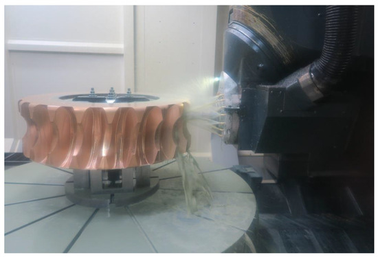
Figure 10.
Manufacturing of worm wheel on universal CNC machine tool.
The worm wheel was manufactured successfully without any adverse events.
5. Experimental Tooth Contact Pattern
The meshing of the worm and worm wheel manufactured on universal CNC machine tools was examined on a gear testing apparatus corresponding to large gears. Afterward, the tooth contact patterns were observed experimentally. Figure 11 shows the worm gear set on a gear testing apparatus. Figure 12 shows the compared results of the analytical and experimental tooth contact patterns on the tooth flank of the worm wheel. Figure 12a,b corresponds to the analytical and experimental tooth contact patterns, respectively. The tooth contact patterns in Figure 12a,b are nearly identical. Consequently, this method of manufacturing a large worm gear set of ISO type I using endmill tools on universal CNC machine tools was validated and found suitable for use.
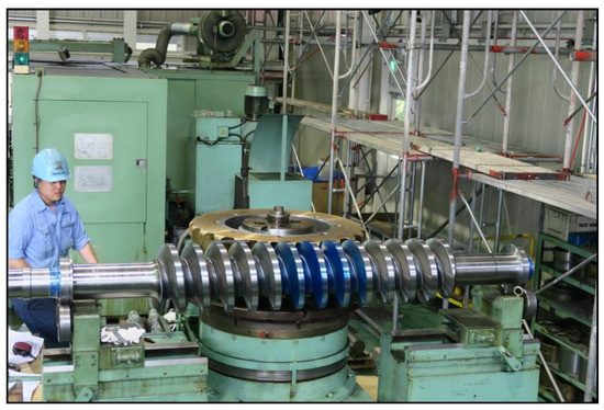
Figure 11.
Worm gear set on gear testing apparatus.
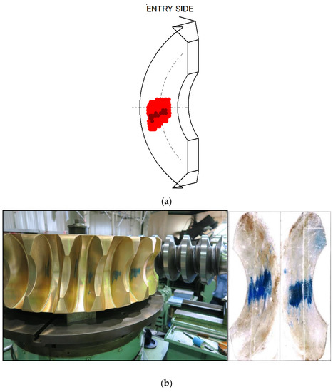
Figure 12.
Compared results of analytical and experimental tooth contact patterns. (a) Analytical tooth contact pattern. (b) Experimental tooth contact pattern.
6. Conclusions
In this paper, a cylindrical worm gear set of ISO type I was manufactured using end mill tools on universal CNC machine tools. The worm was manufactured under the determined cutting conditions by controlling only two axes in a swarf milling method using the side of the endmill tool. Meanwhile, the targeted theoretical tooth flanks of the mating worm wheel were modeled in 3-dimensional CAD software, and the worm wheel was manufactured by a swarf milling method through a CAM process. The experimental and analytical tooth contact patterns were compared, and it was observed that they were nearly identical. Consequently, this method of manufacturing a large worm gear set of ISO type I was validated and found suitable for use. This manufacturing method can be applied to other types, such as ZN, ZA, and ZI worm gear sets.
Author Contributions
Conceptualization, K.K.; Data curation, K.K. and I.T.; Formal analysis, K.K. and I.T.; Investigation, K.K. and I.T.; Methodology, K.K. and I.T.; Resources, K.K. and I.T.; Software, I.T.; Supervision, K.K.; Validation, K.K.; Visualization, I.T.; Writing—original draft, K.K.; Writing—review and editing, K.K. All authors have read and agreed to the published version of the manuscript.
Funding
This research received no external funding.
Institutional Review Board Statement
Not applicable.
Informed Consent Statement
Not applicable.
Data Availability Statement
Data is contained within the article.
Conflicts of Interest
The authors declare no conflict of interest.
Nomenclature
| A, A’ | x components of position vector of generating line of tooth flank of worm in O-xyz |
| B, B’ | y components of position vector of generating line of tooth flank of worm in O-xyz |
| C, C’ | z components of position vector of generating line of tooth flank of worm in O-xyz |
| u, u’ | Variable position parameters on straight line of worm |
| x | Position vectors of tooth flank of worm in O-xyz |
| x | x components of position vector of tooth flank of worm in O-xyz |
| y | y components of position vector of tooth flank of worm in O-xyz |
| z | z components for z-axis of generating line of tooth flank of worm in O-xyz |
| i | Unit vector in the direction of x-axis |
| j | Unit vector in the direction of y-axis |
| k | Unit vector in the direction of z-axis |
| θ, θ’ | Angles of rotation of screw motion of generating line of the worm |
| θ1, θ1’ | Angles of rotation of worm |
| h, h’ | Pitches of screw motion |
| Pz | Axial displacement corresponding to one complete revolution |
| rg | Base cylindrical radius of worm |
| γg | Lead angle on base cylinder of worm |
| ω1 | Angular velocity vector of worm |
| ω2 | Angular velocity vector of worm wheel |
| v1 | Velocity vector of worm |
| v2 | Velocity vector of worm wheel |
| e | Offset distance between worm axis and axis of worm wheel |
| ε | Angular velocity ratio |
| w | Relative velocity of worm wheel with respect to worm |
| n | Surface unit normal of tooth flank of worm |
| x1 | Locus surface of contact lines |
| x2 | Tooth flank of worm wheel |
| A | Coordinate transform matrix with regard to rotation about x-axis |
| n2 | Surface unit normal of x2 |
| Q | Contact point between the worm tooth flank and endmill tool |
| xr | Position vector of point Q in O-xyz |
| T | x component of right side of tooth space |
| nr | Surface unit normal of xr |
| ny | y component of nr |
| d | Diameter of endmill tool |
| nx | x component of nr |
| E | Rotational center of edge of endmill tool |
| xcr | Position vector of E of right side of tooth space in O-xyz |
| xcr | x component of xcr |
| ycr | y component of xcr |
| zcr | z component of xcr |
| nz | z component of nr |
| xcl | Position vector of E of left side of tooth space in O-xyz |
| xcl | x component of xcl |
| ycl | y component of xcl |
| zcl | z component of xcl |
References
- Vullo, V. Gears Volume 1: Geometric and Kinematic Design; Springer: Cham, Switzerland, 2020. [Google Scholar]
- Dudas, I. The Theory & Practice of Worm Gear Drives; Pen-Ton Press: London, UK, 2000. [Google Scholar]
- Davis, J.R. Gear Materials, Properties, and Manufacture; ASM International: Novelty, OH, USA, 2005. [Google Scholar]
- Radzevich, S.P. Dudley’s Handbook of Practical Gear Design and Manufacture, 4th ed.; CRC Press: Boca Raton, FL, USA; Taylor & Francis Group: New York, NY, USA, 2022. [Google Scholar]
- Kacalak, W.; Majewski, M.; Budniak, Z.; Ponomarenkow, J. Worm Gear Drive with Improved Kinematic Accuracy. Materials 2021, 14, 7825. [Google Scholar] [CrossRef] [PubMed]
- Simon, V.V. Characteristics of a New Type of Cylindrical Worm-Gear Drive. ASME. J. Mech. Des. 1998, 120, 139–146. [Google Scholar] [CrossRef]
- Shreehah, T.A.A.; Abdullah, R.A. Modification of Geometry and Technology of Cylindrical Worms. Mach. Sci. Technol. 2006, 10, 539–547. [Google Scholar] [CrossRef]
- Deng, X.; Wang, J.; Horstemeyer, M.F.; Solanki, K.N.; Zhang, J. Parametric Study of Meshing Characteristics with Respect to Different Meshing Rollers of the Antibacklash Double-Roller Enveloping Worm Gear. ASME J. Mech. Des. 2012, 134, 081004. [Google Scholar] [CrossRef]
- Litvin, F.L.; Gonzalez-Perez, I.; Yukishima, K.; Fuentes, A.; Hayasaka, K. Design, simulation of meshing, and contact stresses for an improved worm gear drive. Mech. Mach. Theory 2007, 42, 940–959. [Google Scholar] [CrossRef]
- Chen, W.L.; Tsay, C.B. Contact Characteristics of Recess Action Worm Gear Drives with Double-Depth Teeth. ASME J. Mech. Des. 2011, 133, 111006. [Google Scholar] [CrossRef]
- Jiaxing, Z.; Ilie, K. Static shear strength calculation of plastic helical gears mating with steel worm. Int. J. Precis. Eng. Manuf. 2014, 15, 235–239. [Google Scholar] [CrossRef]
- Sohn, J.; Park, N. Geometric interference in cylindrical worm gear drives using oversized hob to cut worm gears. Mech. Mach. Theory 2016, 100, 83–103. [Google Scholar] [CrossRef]
- Osakue, E.E.; Anetor, L. Design Sizing of Cylindrical Worm Gearsets. FME Trans. 2020, 48, 31–45. [Google Scholar] [CrossRef]
- Shi, Z.; Ren, J.; Feng, Z.; Li, J. Key Technology and Experimental Study of Unequal Pitches Meshing between Metal Worm and Plastic Helical Gears. Appl. Sci. 2021, 11, 333. [Google Scholar] [CrossRef]
- Liu, Y.; Zhao, Y.; Chen, X.; Li, G. Meshing theory of axial arc tooth profile cylindrical worm drive. Adv. Mech. Eng. 2021, 13, 16878140211012519. [Google Scholar] [CrossRef]
- Mu, S.; Zhao, Y.; Zhang, X.; Meng, Q.; Li, G. Meshing theory of involute worm drive. Mech. Mach. Theory 2021, 165, 104425. [Google Scholar] [CrossRef]
- Deng, X.; Hong, L.; Li, W.; Wang, S.; Liu, Y. High precision machining of ZC1 worm gear drives with large modulus. Mech. Mach. Theory 2021, 165, 104437. [Google Scholar] [CrossRef]
- Boral, P.; Gołębski, R. Technology of Manufacturing of ZC Cylindrical Worm. Materials 2022, 15, 6412. [Google Scholar] [CrossRef]
- Balajti, Z. Determination of Undercutting Avoidance for Designing the Production Technology of Worm Gear Drives with a Curved Profile. Machines 2023, 11, 56. [Google Scholar] [CrossRef]
- Sergej, N.G.; Martinov, G.M. Research and Development of a Cross-Platform CNC Kernel for Multi-Axis Machine Tool. Procedia CIRP 2014, 14, 517–522. [Google Scholar]
- Nakamoto, Y.; Takeuchi, Y. Recent Advances in Multi-Axis Control and Multitasking Machining. Int. J. Autom. Technol. 2017, 11, 140–154. [Google Scholar] [CrossRef]
- Suh, S.H.; Jih, W.S.; Hong, H.D.; Chung, D.H. Sculptured surface machining of spiral bevel gears with CNC milling. Int. J. Mach. Tools Manuf. 2001, 41, 833–850. [Google Scholar] [CrossRef]
- Kawasaki, K.; Tsuji, I.; Abe, Y.; Gunbara, H. Manufacturing Method of Large-Sized Spiral Bevel Gears in Cyclo-Palloid System Using Multi-Axis Control and Multi-Tasking Machine Tool. Proc. Int. Conf. Gears 2010, 1, 337–348. [Google Scholar]
- Yang, L.; Huang, G. The OPC technology research about spiral bevel gear machine tools for machining simulation problems. Procedia Eng. 2011, 15, 1266–1270. [Google Scholar] [CrossRef]
- Alves, J.T.; Guingand, M.; Vaujany, J. Designing and Manufacturing Spiral Bevel Gears Using 5-Axis Computer Numerical Control (CNC) Milling Machines. ASME J. Mech. Des. 2013, 135, 024502. [Google Scholar] [CrossRef]
- Deng, X.Z.; Li, G.G.; Wei, B.Y.; Deng, J. Face-milling spiral bevel gear tooth surfaces by application of 5-axis CNC machine tool. Int. J. Adv. Manuf. Technol. 2014, 71, 1049–1057. [Google Scholar] [CrossRef]
- Lei, B.; Cheng, G.; Lowe, H.; Wang, X. Remanufacturing the Pinion: An Application of a New Design Method for Spiral Bevel Gears. Adv. Mech. Eng. 2014, 2014, 257581. [Google Scholar] [CrossRef]
- Alvarez, A.; Lacalle, L.N.L.; Olaiz, A.; Rivero, A. Large spiral bevel gears on universal 5-axis milling machines: A complete process. Procedia Eng. 2015, 132, 397–404. [Google Scholar] [CrossRef]
- Malek, O.; Mielnik, K.; Martens, K.; Jacobs, T.; Bouquet, J.; Auwers, W.; Ten Haaf, P.; Lauwers, B. Lead time reduction by high precision 5-axis milling of a prototype gear. Procedia CIRP 2016, 46, 440–443. [Google Scholar] [CrossRef]
- Gosselin, C. Gear Tooth Edge Deburring and Chamfering in 5Axis CnC Manufacturing. Mech. Mach. Sci. 2021, 101, 153–184. [Google Scholar]
- Ozel, C.; Inan, A.; Ozler, L. An Investigation on Manufacturing of the Straight Bevel Gear Using End Mill by CNC Milling Machine. ASME J. Mech. Des. 2005, 127, 503–511. [Google Scholar]
- Kawasaki, K.; Tsuji, I.; Gunbara, H.; Houjoh, H. Method for remanufacturing large-sized skew bevel gears using CNC machining center. Mech. Mach. Theory 2015, 92, 213–229. [Google Scholar] [CrossRef]
- Gadakh, R.S.; Londhe, P.G.; Shaikh, B.A.; Shaikh, F.S. Gear Manufacturing by Using Conventional Lathe Machine. Int. J. Res. Eng. Technol. 2016, 5, 105–110. [Google Scholar]
- Gołębskiby, R.; Boral, P. Study of Machining of Gears with Regular and Modified Outline Using CNC Machine Tools. Materials 2021, 14, 2913. [Google Scholar] [CrossRef]
- Gołębskiby, R. Experimental Method of Machining Gears with an Involute Profile Using CNC Lathe with Driven Tools. Materials 2022, 15, 1077. [Google Scholar] [CrossRef] [PubMed]
- Kawasaki, K.; Tsuji, I.; Gunbara, H. Manufacturing method of double-helical gears using CNC machining center. Proc. Inst. Mech. Eng. Part C J. Mech. Eng. Sci. 2015, 230, 1149–1156. [Google Scholar] [CrossRef]
- Kawasaki, K.; Tsuji, I. Machining method of large-sized cylindrical worm gears with Niemann profiles using CNC machining center. Int. J. Adv. Manuf. Technol. 2019, 104, 3717–3729. [Google Scholar] [CrossRef]
- Sakai, T. A Study on the Tooth Profile of Hypoid Gears. Trans. JSME 1955, 21, 164–170. (In Japanese) [Google Scholar] [CrossRef]
- Litvin, F.L.; Fuentes, A. Gear Geometry and Applied Theory, 2nd ed.; Cambridge University Press: Cambridge, UK, 2004. [Google Scholar]


Disclaimer/Publisher’s Note: The statements, opinions and data contained in all publications are solely those of the individual author(s) and contributor(s) and not of MDPI and/or the editor(s). MDPI and/or the editor(s) disclaim responsibility for any injury to people or property resulting from any ideas, methods, instructions or products referred to in the content. |
© 2023 by the authors. Licensee MDPI, Basel, Switzerland. This article is an open access article distributed under the terms and conditions of the Creative Commons Attribution (CC BY) license (https://creativecommons.org/licenses/by/4.0/).