Highlights
What are the main findings?
- This review compares two main folding-wing configurations—lateral and longitudinal—assessing their trade-offs in terms of performance, efficiency, and structural complexity.
- It also evaluates dual-use and hybrid propulsion systems, emphasizing the challenges of integration, mass, and energy efficiency across different media.
What are the implications of the main findings?
- The study presents a comprehensive approach for High-Altitude Aerial Vehicles (FUDs), focusing on advanced materials, intelligent control systems, and innovations in energy to address existing challenges.
- It emphasizes the significant transformative potential of FUDs for both military and civilian use, urging targeted efforts to tackle critical bottlenecks and explore emerging technologies such as swarm operation and energy recovery.
Abstract
The evolution of modern warfare and civil exploration requires platforms that can operate seamlessly across the air–water interface. The folding-wing Hybrid Air and Underwater Vehicle (FUD) has emerged as a transformative solution, combining the high-speed cruising capabilities of fixed-wing aircraft with the stealth characteristics of underwater navigation. This review thoroughly analyzes the advancements and challenges in folding-wing FUD technology. The discussion is framed around four interconnected pillars: the overall design driven by morphing technology, adaptation of the propulsion system, multi-phase dynamic modeling and control, and experimental verification. The paper systematically compares existing technical pathways, including lateral and longitudinal folding mechanisms, as well as dual-use and hybrid propulsion strategies. The analysis indicates that, although significant progress has been made with prototypes demonstrating the ability to transition between air and water, core challenges persist. These challenges include underwater endurance, structural reliability under impact loads, and effective integration of the power system. Additionally, this paper explores promising application scenarios in both military and civilian domains, discussing future development trends that focus on intelligence, integration, and clustering. This review not only consolidates the current state of technology but also emphasizes the necessity for interdisciplinary approaches. By combining advanced materials, computational intelligence, and robust control systems, we can overcome existing barriers to progress. In conclusion, FUD technology is moving from conceptual validation to practical engineering applications, positioning itself to become a crucial asset in future cross-domain operations.
1. Introduction
The evolution of modern warfare and civil exploration increasingly requires equipment capable of operating seamlessly across multiple domains, especially at the challenging air–water interface [1]. Traditional single-medium platforms often fall short when it comes to penetrating sophisticated defense systems or executing complex missions in littoral environments. In response to this need, folding-wing FUDs have emerged as a transformative solution, combining the high-speed, long-endurance capabilities of fixed-wing aircraft with the stealth and concealment of underwater navigation [2]. This dual functionality enables unprecedented mission profiles, ranging from rapid aerial penetration to covert underwater reconnaissance and strike operations [3].
The core scientific challenge of FUD development lies in managing the significant differences in physical properties between air and water. This disparity generates extreme dynamic loads during medium transitions, requiring fundamentally different design paradigms for propulsion, stability, and control. These challenges are not only complex but even more severe than those encountered in other demanding flow environments. For example, the unsteady and turbulent nature of ocean wind fields significantly impacts the flight stability and control of FUDs, necessitating robust adaptive control strategies. Advanced flow control methods, such as adaptive wing morphing and plasma actuators [4,5,6], have been created to manage flow separation and improve the maneuverability of FUDs in adverse conditions [7]. Recent advancements in computational intelligence provide powerful new tools to tackle these multifaceted design challenges [8]. The application of ANNs and ML in aerodynamic optimization has shown remarkable success in predicting complex flow fields and developing optimal control laws for nonlinear systems. These data-driven approaches are particularly well-suited for modeling the challenging multiphase flow dynamics and fluid–structure interactions involved in cross-medium transitions. FUDs must therefore address a broader range of extreme aerodynamic and hydrodynamic phenomena.
Although existing reviews have documented various prototypes, there is a lack of comprehensive analysis that situates these developments within the context of broader aerospace challenges and modern computational methodologies [9,10]. This paper conducts a comparative study that identifies historical progress as well as the underlying technical bottlenecks faced by FUDs. It provides a systematic review that consolidates the state-of-the-art in folding-wing FUD technology and critically examines it through advanced perspectives. The study explicitly outlines future development trajectories that integrate machine learning and advanced flow control technologies, thereby guiding future research toward the most promising interdisciplinary solutions.
The technological challenge of designing a viable folding-wing FUD can be conceptualized as a system of three interdependent pillars:
- Overall Layout: Given the starkly different physical media of air and water, the overall design of an FUD is essential for balancing aerodynamic and hydrodynamic performance through bionic and morphing technologies.
- Propulsion System: Current engine performance is significantly inadequate. The engine must provide efficient thrust in both air and water, or multiple systems must be integrated without incurring a prohibitive weight penalty.
- Dynamics Modeling and Control: FUDs must maintain stability amidst drastic dynamic changes and external disturbances; therefore, accurate models of multiphase fluid–structure interactions are needed to simulate the violent transition process and predict loads.
- Experimental Verification: A graduated testing regimen, from laboratory benches to open water, is essential to validate designs and models under complex sea condition disturbances.
2. Research Status of Folding-Wing FUD Technology
Since the concept of “flying submarines” was first proposed by the Soviet Union in the 1930s [11,12], research on folding-wing hybrid aerial-aquatic vehicles (FUDs) has been predominantly carried out in the United States and the United Kingdom [13,14]. Development efforts are largely driven by military applications, with multiple technical pathways being pursued concurrently. These initiatives have led to substantial progress in the development and validation of key technologies [15,16]. Currently, academic institutions play a leading role in this domain, with a focus on bio-inspired design and autonomous control [17,18]. Distinct technical approaches have been established in areas such as morphing structures and dynamic modeling, and several prototypes have successfully undergone proof-of-concept validation. Prominent examples include Convair Submersible Seaplane [19], “TJ-FlyingFish” [20,21], Aalborg University’s FUD, “Novel Multimodal SAAV” [22], and “gliding HAUV” [23], Johns Hopkins University’s triangle-wing FUD [24].
The overall design of FUDs must satisfy dual operational requirements: low aerodynamic drag during high-speed flight and minimized hydrodynamic resistance during underwater navigation. Morphing technology serves as the core method to achieve this objective. Based on the folding direction, it can be categorized into two types: lateral folding along the wingspan (variable-sweep) and longitudinal folding along the chord (see Figure 1). These designs are inspired by the body structures and locomotion mechanisms of natural transmedia organisms (see Figure 2)—such as flying fish, boobies, and kingfishers—to achieve adaptive morphology-function matching [25,26].
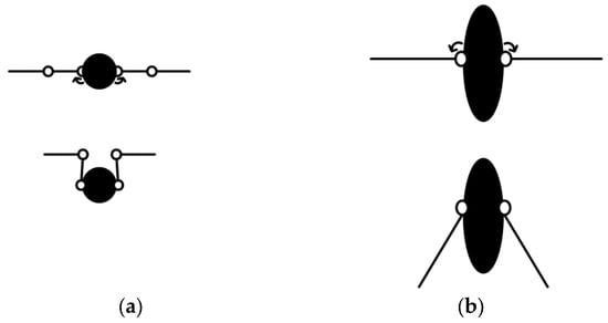
Figure 1.
Classification of FUD. (a) Lateral-folding wing FUD; (b) Longitudinal-folding wing FUD. Reprinted with permission from Ref. [27]. Copyright 2018, Yang X.B. et al.
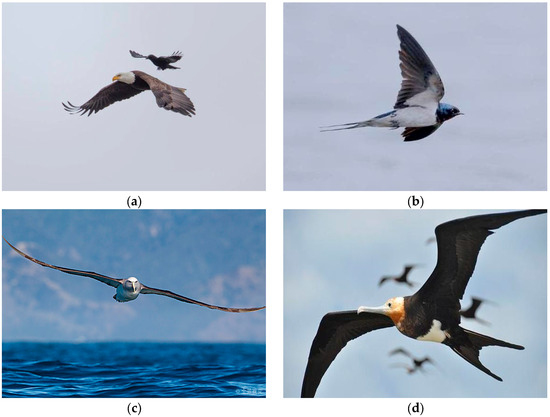
Figure 2.
Common bionic objects. (a) Eagle; (b) Swift; (c) Albatross; (d) Frigatebird.
The principal advantage of folding-wing technology is its high spatial efficiency, making it particularly suitable for submarine-launched scenarios. However, it often entails challenges such as high mechanism complexity and reduced reliability after repeated folding cycles. For instance, a fixed-wing FUD developed at North Carolina State University in 2016 exhibited hinge wear after 50 folding tests, resulting in a reduction in folding accuracy to 0.5 mm and necessitating regular maintenance and part replacement [28,29,30].
2.1. Lateral-Folding Wing FUD
Lateral-folding wings adjust the sweep angle to modify wingspan and aspect ratio, enabling adaptation to different flight environments. During aerial flight, a low sweep angle (15–30°) is typically employed to increase the aspect ratio to 4–6, thereby improving the lift-to-drag ratio. During underwater navigation, a high sweep angle (50–70°) is used to reduce wingspan and minimize drag. The benefits of this approach include a mature design process and a broad range of adjustments. Key limitations, however, include significant structural stresses at the wing root hinge, making it prone to fatigue damage—for example, after 100 media transition tests, the “Longbow 2” exhibited a crack initiation rate of 15% at the wing root. Additionally, sweep angle variation shifts the center of gravity, necessitating compensation through fuel transfer or the addition of ballast, which in turn increases system complexity [31,32,33].
In 2009, Beihang University developed a bionic cross-media prototype of the “Flying Fish” (see Figure 3). This model mimics the movement mechanism of the pectoral fins of flying fish, adopting a 90° variable-sweep wing design in plane deformation. It has an aerial wingspan of 1.8 m, is propelled by propellers, and achieves a cruising speed of 45 km/h. Underwater, buoyancy is adjusted by the ballast water tank to achieve descent and ascent, with a maximum diving depth of 10 m. The “Flying Fish” is the first fixed-wing prototype in China that achieves underwater navigation and bidirectional transition between water and air. However, due to limitations in its power system, its takeoff speed is relatively slow, requiring a 50 m water-surface glide for acceleration, and its underwater endurance is only 30 min [34].
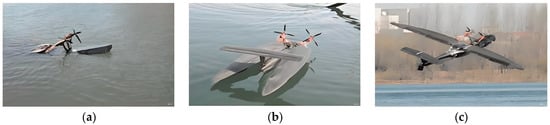
Figure 3.
“Flying Fish” of BUAA. (a) Cross-water stage; (b) Gliding on the water surface; (c) Taking off from the water surface. Reprinted with permission from Ref. [34]. Copyright 2009, Liu H.X.
In 2012, MIT proposed a folding-wing FUD design (see Figure 4). Addressing the inability of the “Cormorant” to achieve bidirectional media crossing, this design incorporated a longitudinally folding wing structure driven by a servomotor at the hinge, achieving full folding within 0.25 s. The mechanism was constructed from carbon fiber composites, accounting for only 8% of the total vehicle mass. However, backlash in the gear transmission resulted in excessive vibration during high-speed adjustment. This vehicle focused on validating unidirectional air-to-water transition capability: during water entry, the wings fold into a spindle shape to reduce impact resistance. However, due to limitations in the propulsion system design, autonomous underwater propulsion was not achievable, and the folding mechanism only supported a single operation, making it unsuitable for repeated cross-media missions [35].
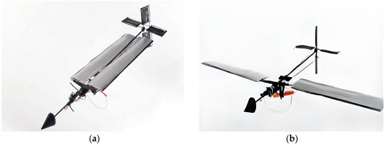
Figure 4.
FUD of MIT. (a) Folded state; (b) Unfolded state. Reprinted with permission from Ref. [35]. Copyright 2012, Fabian A. et al.
In 2013, Beihang University developed an FUD based on the body contraction and wing-folding actions of a booby when it enters water (see Figure 5). The FUD features a variable-sweep wing configuration, with the wing sweep angle adjustable from 0° to 60°. The fuselage features a streamlined design, with a head curvature radius of 15 mm, compared to approximately 30 mm for traditional models. After the wings are folded, the length-to-diameter ratio of the fuselage reaches 8:1. The water inlet resistance coefficient is reduced by 40%. The team analyzed the flow field characteristics at different water entry angles 0°~30° through CFD simulation and found that at a water entry Angle of 15°, the area of cavitation formation was the smallest and the impact load was the most uniform, providing a basis for the design of the water entry posture of subsequent models [36].
Figure 5.
Bionic “booby” of Beihang University. Reprinted with permission from Ref. [37]. Copyright 2013, Yang X.B. et al.
In 2014, Imperial College London developed the AquaMAV (see Figure 6), an innovative design that incorporates a lightweight, laterally folding wing and a CO2-Water Jet propulsion system. The wingspan is 592 mm, with a total mass of 100 g. It is propelled through the air by propellers and gliders at a speed of 11 m per second. Underwater, high-pressure water jets are generated by liquid CO2 gas tanks to achieve a vertical water outlet at up to 7 m per second. The wings are made of carbon fiber in one piece and fold using SMA, with a folding time of 0.3 s and a drive system weight of only 20 g. The diameter of the SMA wire is 0.5 mm. After being powered on, its shrinkage rate reaches 4%, providing sufficient driving force. However, the response speed of SMA is greatly affected by temperature. The underwater low-temperature environment (0–5 °C) can extend folding time to 0.8 s, thereby affecting the medium’s conversion efficiency [38,39].
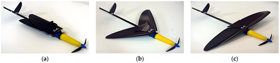
Figure 6.
AquaMAV of Imperial College London. (a) Folded state; (b) Half-folded state; (c) Unfolded state. Reprinted with permission from Refs. [38,39]. Copyright 2017–2019, Siddall R. et al.
In 2022, Harbin Engineering University developed the “Longbow 2” (see Figure 7). This model features a variable-sweep wing design, with a wingspan of 2.5 m and a fuselage length of 1.9 m. It is equipped with an oil-electric hybrid propulsion system: The propeller is driven by a piston engine in the air, with a cruising speed of 120 km/h and an endurance of 120 min. Underwater, it switches to electric propulsion, reaching 3 m/s and a maximum diving depth of 30 m. The variable swept-back wing technology adopted by “Longbow 2” further integrates an adaptive adjustment algorithm. It collects parameters such as airspeed, water speed, and medium density in real time via sensors. It automatically matches the optimal swept-back angle of 20° during air cruise, with a lift-to-drag ratio of 14. When submerged, the sweepback Angle is 60°, and the underwater drag coefficient is only 0.08. Tests show that this adaptive adjustment can increase the attitude stability by 30% during the medium conversion process [40].
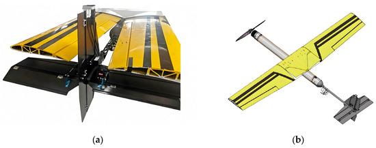
Figure 7.
“Longbow 2” of Harbin Engineering University. (a) Folded state; (b) Unfolded state. Reprinted with permission from Ref. [40]. Copyright 2024, Wang B.X.
2.2. Longitudinal-Folding Wing FUD
In 2005, Lockheed Martin initiated the engineering development of the folding-wing FUD “Cormorant” (see Figure 8). Its three-segment lateral folding mechanism divides the wing into inner, middle, and outer sections, actuated via a hydraulically driven hinge. When folded, the wingspan reduces from 5.8 m to 1.2 m, allowing deployment from a submarine’s 533 mm missile launch tube. A critical feature of this design is the folding lock mechanism, which utilizes a wedge-shaped latch and a spring pre-tightening system to achieve an unfolding positional accuracy of 0.1 mm and withstand aerodynamic loads of up to 12 kN. Drawbacks include the weight of the hydraulic system, which accounts for 12% of the total mass, and stringent sealing requirements for underwater operations. The vehicle uses a turbofan engine for aerial propulsion, achieving speeds up to Mach 0.8, and relies on a gas ejection system for water exit. In 2006, the “Cormorant” completed splashdown and recovery tests, providing a valuable technical reference for subsequent models [25].
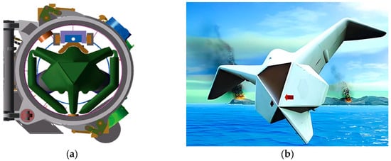
Figure 8.
Lockheed Martin’s Cormorant submarine-launched uncrewed aerial vehicle. (a) Folded state, suitable for submarine launch tubes; (b) Unfolded state, used for air cruise. Reprinted with permission from Ref. [25]. Copyright 2013, Weisshaar T.A.
In 2011, Nanchang Hangkong University developed an oil-electric hybrid and all-electric FUD, which adopted a variable swept-back structure of 90 degrees to reduce drag (see Figure 9). The aircraft is powered by tail propellers both underwater and on the water surface. Power is provided by the propellers at the front of the fuselage when flying in the air. Researchers tested its feasibility and found that it had excessive resistance during takeoff and insufficient power, thus failing to complete the task of taking off from the water surface [41].
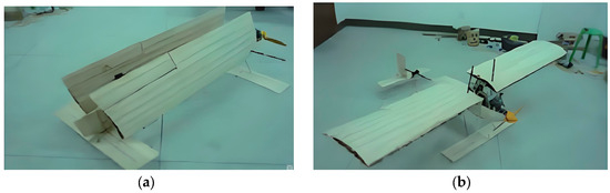
Figure 9.
FUD of Nanchang Hangkong University. (a) Folded state; (b) Unfolded state. Reprinted with permission from Ref. [41]. Copyright 2012, Zhu S.
In 2020, Central South University designed a three-section, foldable “Kingdee” (see Figure 10). The wings are divided into three sections along the wingspan direction: inner, middle, and outer. It mimics the sharp, blunt-tipped transition structure of the kingbird’s beak. The nose features a gradient curvature design with a 5 mm radius at the front end and a 20 mm radius in the middle, effectively suppressing the formation of air bubbles and reducing resistance when entering water. Folding and unfolding are achieved through a multi-hinge mechanism. When unfolded in the air, the wingspan measures 2.0 m, and the lift-to-drag ratio reaches 12. After underwater folding, the wingspan is reduced to only 0.8 m, and the underwater drag coefficient is decreased by 35%. It is powered by a single electric motor, boasting an in-flight endurance of 40 min and an underwater speed of 1.5 m per second. The improvement in hydrodynamic performance resulting from the variant structure was verified through water tunnel tests. However, the soft hinge’s stiffness is insufficient, leading to excessive wing shaking at high speeds [42].
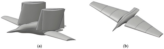
Figure 10.
“Kingdee” of Central South University. (a) Folded state; (b) Unfolded state. Reprinted with permission from Ref. [42]. Copyright 2019, Yun Z. et al.
2.3. Comparison of Various Folding-Wing FUD
This section provides a clear comparison of six representative models of folding-wing FUDs across four key aspects: airfoil structure, propulsion mode, aerial-aquatic performance, and medium-crossing capability. The analysis highlights three significant challenges that current folding-wing FUDs face: limited underwater endurance, substantial impact loads during transitions between mediums, and limitations in power system integration. Addressing these issues will be crucial for future research and development (see Table 1).

Table 1.
Performance Comparison of Typical Folding-wing FUD.
FUD technology is progressively evolving from conceptual validation to practical, high-performance applications. Lateral-folding configurations continue to dominate due to their structural simplicity and reliability. The investigation into longitudinal and multi-stage folding indicates a pursuit of enhanced spatial efficiency and hydrodynamic design.
For aerial propulsion, propellers are favored for their high efficiency at lower speeds, making them well-suited for small and medium-sized FUDs. Electric propulsion, with its technological maturity and precise control, is predominant in underwater operations. Additionally, this comparison reveals a distinct trade-off between aerial performance and aquatic capabilities.
The challenge of medium transitioning remains critical. The variety of technical solutions reflects the complexity of transitioning from water to air, with various institutions pursuing different strategies to tackle this issue. Splash-down is the most commonly employed method for transitioning from air to water, primarily due to its simplicity. Notably, Harbin Engineering University’s “Longbow 2” has made strides in achieving controlled water entry, marking a significant technological advancement that enhances mission reliability and stealth.
3. Propulsion System Technology
Cross-medium propulsion systems must simultaneously adapt to two vastly different media: air (density 1.2 kg/m3, viscosity 1.8 × 10⁻⁵ Pa·s) and water (density 1000 kg/m3, viscosity 1.0 × 10⁻³ Pa·s). The core challenges lie in power matching and mode transition. Currently, propulsion solutions for folding-wing FUD can be categorized into air-water dual-use propulsion systems and hybrid propulsion systems. The research progress for each is as follows:
3.1. Air–Water Dual-Use Propulsion Systems
Air–water dual-use propulsion systems use a single device to deliver power to both media. The core challenges involve multi-medium adaptation of propellers/thrusters and broad operational adaptation of power sources, which significantly reduce system mass and complexity, making this the mainstream direction for future development.
- Dual-use propeller technology: The key to dual-use propeller technology lies in airfoil design and material selection (see Figure 11). Traditional aerial propellers utilize high-lift-to-drag-ratio airfoils, such as NACA 2412, which results in low efficiency underwater. Traditional underwater propellers use thick airfoils, such as NACA 66, which cause high drag during aerial flight. To resolve this, Johns Hopkins University proposed a variable-section propeller solution in 2018. The blade root adopts an underwater-adapted airfoil 15% thickness, the mid-section a transitional airfoil 10% thickness, and the tip an aerial-adapted airfoil 8% thickness. Through CFD optimization, this propeller achieved an aerial propulsion efficiency of 0.75 and an underwater efficiency of 0.65, a 20% improvement over traditional single-airfoil propellers. In 2019, the National University of Singapore employed carbon fiber-reinforced polyether ether ketone CF/PEEK for its propellers. This material has a density of 1.4 g/cm3 and a tensile strength of 1.2 GPa, capable of withstanding pressures at a depth of 30 m, approximately 0.3 MPa, and exhibiting excellent corrosion resistance, with no significant degradation after 500 h in a salt spray environment. The propeller features a swept-back design, operating at 2000 rpm during aerial cruise and 800 rpm during underwater navigation. Motor speed adjustment enables multimedia adaptation, but the high cost limits mass production [43].

Figure 11.
Dual-use propeller. Reprinted with permission from Ref. [44]. Copyright 2021, Shan R.L.

- Advanced electric propulsion: For power sources, electric propulsion is the primary choice due to its simple structure and convenient speed control. However, traditional lithium batteries have a low energy density, which limits their endurance. In 2017, Harvard University adopted a hydrogen-oxygen fuel cell and a water electrolyzer regeneration system. The fuel cell extends aerial endurance from 10 min with lithium batteries to 30 min. Underwater, electrolysis produces hydrogen and oxygen for fuel cell regeneration; however, the process consumes significant energy, making it suitable only for micro-FUDs [45,46].
- Metal-fuel engines: Metal-fuel engines are a potential direction for large-sized FUD (see Figure 12). Liu proposed an aluminum-water reaction engine that uses aluminum powder as fuel and seawater as the oxidizer, providing continuous thrust. The engine operates via hydrogen-oxygen combustion in air and an aluminum-water reaction underwater, far exceeding that of lithium batteries. However, challenges remain in achieving uniform mixing of aluminum powder with seawater and in expelling the reaction product alumina. Currently, only ground tests have been conducted at 100 N thrust for 5 min [47,48].

Figure 12.
Particle-phase distribution in metal-fuel engines. Reprinted with permission from Ref. [49]. Copyright 2018, Liu P.A. et al.

- Ramjet engine: The National University of Defense Technology has proposed a cross-media ramjet engine scheme (see Figure 13). This power scheme enables the integration of air and underwater power units, allowing for high-speed navigation of aircraft at all stages of flight. This power system utilizes a metal-based oxygen-poor propellant as its primary fuel. It is primarily composed of components such as the air inlet, water inlet pipeline, gas generator, supplementary combustion chamber, and tail nozzle. Metal-based oxygen-poor propellants burn in the gas generation chamber to produce rich combustion gas. During the flight phase in the air, the produced flame-retardant gas reacts with the air entering the air intake in the supplementary combustion chamber and is sprayed out by the nozzle to provide thrust. During the underwater navigation stage, the metal particles in the rich combustion gas produced react with the seawater entering through the water inlet pipeline in the supplementary combustion chamber. On the one hand, the reaction generates hydrogen gas, which is discharged through the nozzle to generate thrust. On the other hand, the reaction releases heat, causing the water working medium in the secondary water inlet to evaporate and expand, doing work and generating thrust. The power scheme can achieve a high-altitude cruise Mach number of 2.5, a sea-crossing Mach number of 2.3, and an underwater navigation speed of 141 m/s. Currently, the power scheme for water-air dual-purpose ramjet engines remains in the conceptual design stage. Although the feasibility of this power system scheme has been theoretically demonstrated, several key technologies still need to be addressed before it can be applied in practical engineering [50].

Figure 13.
Preliminary conceptual diagram of a boron-based transmedia ramjet engine. Reprinted with permission from Ref. [51]. Copyright 2020, Chen W.W. et al.

3.2. Hybrid Propulsion Systems
Hybrid Propulsion Systems involve multiple propulsion systems that can work together or separately. Hybrid propulsion systems combine the advantages of numerous independent and dual-use propulsion systems, selecting the optimal mode for each mission phase. This approach boasts high technological maturity and is the mainstream choice. The advantages of hybrid Propulsion Systems include low technical risk and stable performance. However, they suffer from high mass and low integration, making them unsuitable for small FUD [52,53].
Lockheed Martin’s “Cormorant” uses a combination of a turbofan engine and a gas catapult. For aerial propulsion, a scaled-down version of the F404 turbofan engine is utilized, producing 2.5 kN of thrust with a thrust-to-weight ratio of 7.5, which enables a cruise speed of Mach 0.8. However, it lacks autonomous underwater propulsion and relies on a gas catapult device from a submarine launch tube to achieve a water-ejection speed of 15 m/s. This solution offers robust aerial thrust but relies on external equipment for underwater operations, thereby limiting its fully autonomous cross-media functionality [54].
In 2016, North Carolina State University’s fixed-wing FUD adopted a piston-engine and electric-propeller solution (see Figure 14). Aerial propulsion was achieved using a Rotax 912 80 kW power piston engine driving a two-blade propeller, with a cruise speed of 72 km/h. Underwater propulsion utilized a brushless 5 kW DC motor, driving a 0.6 m-diameter three-blade propeller, which achieved a speed of 2 m/s. A clutch mechanism enabled power switching, disengaging the underwater motor during flight to avoid deadweight. However, the two propulsion systems accounted for 35% of the total mass, reducing the effective payload by only 2 kg [55].
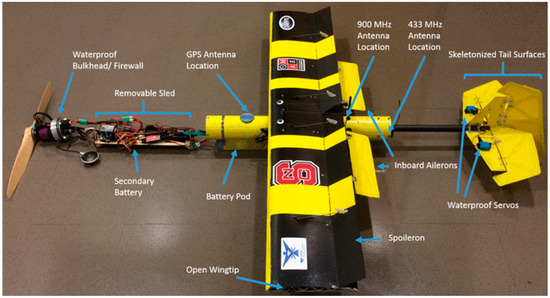
Figure 14.
The structure of North Carolina State University’s fixed-wing FUD. Reprinted with permission from Ref. [55]. Copyright 2018, Stewart W. et al.
Imperial College London’s AquaMAV uses both CO2 waterjet and a propeller propulsion system (see Figure 15). During water exit, 30 MPa liquid CO2 is ejected to generate a thrust of 50 N, enabling rapid water exit at 7 m/s. During aerial and underwater cruises, it switches to propeller propulsion at 100 W, providing 14 min of aerial endurance and 8 min of underwater endurance. This solution provides fast water exit and is suitable for emergency penetration scenarios. However, the CO2 tank supports only a single exit, and high-pressure tank safety is a concern due to the risk of explosion in the event of impact [56,57].
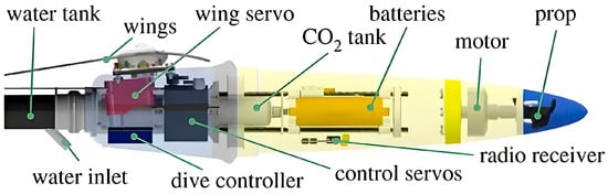
Figure 15.
Structure of Imperial College London’s AquaMAV. Reprinted with permission from Refs. [56,57]. Copyright 2014–2015, Siddall R. et al.
Harbin Engineering University introduced an oil-electric hybrid and shared transmission shaft design in the “Longbow 2” project (see Figure 16). During an aerial cruise, a turboprop engine with 300 kW of power enables a cruise speed of 150 km/h and a 180 min endurance. During underwater navigation, an electric propeller with 10 kW of power provides a speed of 4 m/s. The aerial piston engine and underwater motor drive the propeller via a single transmission shaft, reducing the mass of transmission components by 15%. However, a CVT is required to match the rotational speeds of the piston engine and the motor. In 2024, Harbin Engineering University proposed a thrust rocket booster and turboprop propulsion solution to enable rapid water exit from a depth of 10 m to the surface at an exit speed of 12 m per second. This solution reduces the water exit time from 10 s to 2 s, thereby lowering the detection probability. However, the disposable rocket booster significantly increases operational costs [58].
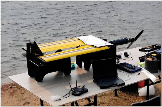
Figure 16.
Equipment of “Longbow 2”. Reprinted with permission from Ref. [40]. Copyright 2024, Wang B.X.
4. Dynamics Modeling and Control Technology
Multi-medium dynamic modeling must account for variations in forces and moments across different media, including aerodynamic, hydrodynamic, buoyancy, gravitational, and thrust forces. The core challenges lie in dynamically adapting medium-specific parameters and maintaining model coherence during transition phases.
4.1. Multi-Phase Flow Dynamics Modeling and Control
Multi-medium dynamics modeling must account for variations in force and moment across different media, including aerodynamic, hydrodynamic, buoyancy, gravity, and thrust forces. The core challenges are the dynamic adaptation of medium parameters and model cohesion during transition phases.
- Aerial flight phase: The dynamics during aerial flight can be described using a 6-DOF model applicable to conventional fixed-wing aircraft, emphasizing lift, drag, and pitching moment coefficients. Tang developed an aerodynamic model based on wind-tunnel data, in which these coefficients are functions of Mach number and angle of attack, with a model error of less than 5% [59].
- Underwater navigation phase: For underwater operation, the dynamic model must incorporate hydrodynamic forces such as viscous drag, inertial forces, and added-mass effects. Hou established a 6-DOF model grounded in potential flow theory, integrating added-mass coefficients to capture the influence of water on vehicle motion. These coefficients were validated through water-tunnel experiments, demonstrating an error of less than 8% across speeds ranging from 0.5 to 5 m/s [17].
- Medium transition phase: Modeling the medium transition phase is particularly challenging due to the involvement of two-phase gas–liquid flow and free-surface effects (see Figure 17). Control strategies for cross-media motion must adapt to the differing dynamics in air, water, and transition phases. Conventional single-medium control laws prove insufficient, necessitating multi-mode adaptive control frameworks. During water entry or exit, rapid attitude adjustments are essential to mitigate impact loads. Wang proposed a segmented coupling model that divides the transition into three regions: the near-surface air domain, the gas–liquid mixing domain, and the near-bottom water domain. Each region employs distinct force models: the near-surface region accounts for aerodynamic forces and surface tension [60,61]. The mixing domain utilizes the VOF multiphase model to compute interfacial tension and cavitation-induced troops, and the near-bottom region considers only hydrodynamic forces. This approach accurately simulates variations in impact loads during water entry. At an entry velocity of 8 m/s, the deviation in peak impact acceleration is merely 3% compared to experimental data. In addition, Wang developed an adaptive control law employing fuzzy logic to identify the medium state and autonomously adjust control parameters. Attitude gain values are elevated to hasten response in the gas–liquid mixed domain and reduced to prevent overshoot in water. Experimental validation confirms that this method restricts attitude error during water entry to within 1° and reduces peak impact acceleration by 15% [62].

Figure 17.
An imagined motion profile of an FUD. Reprinted with permission from Ref. [63]. Copyright 2024, Liu Y. et al.

- Water Surface Effect: The Water Surface Effect significantly influences FUD operation during surface-level flight (see Figure 18 and Figure 19). This aerodynamic phenomenon occurs when downwash airflow is obstructed by the water surface, leading to increased pressure under the wing, enhanced lift, and reduced induced drag. Its effective altitude typically remains below half the wingspan. Although it improves the lift-to-drag ratio, it introduces challenges related to the coupling of multiphase flow. Wake-induced surface deformations—such as depression, splash, or penetration—can cause thrust fluctuations of 12–15% and pose risks of lift loss or stall. Numerical and experimental studies indicate that density and viscosity disparities between air and water, combined with environmental factors such as sea breezes, waves, and currents, result in an unsteady, periodically fluctuating mixed flow of air and water. This complicates the modeling and measurement of multiphase flows. Current models, including Cheeseman and PSM, exhibit limited accuracy in predicting near-surface behaviors. Future efforts should prioritize the development and validation of high-fidelity, coupled pneumatic-hydraulic models [64].

Figure 18.
Mixed air-water flows induced by the multi-rotor. Reprinted with permission from Ref. [65]. Copyright 2025, Wang Y. Et al.


Figure 19.
Schematic of the WIG craft flying over wavy ground. Reprinted with permission from Ref. [66]. Copyright 2007, Qu Q.L. et al.

- Cavitation-bubble formation: At high-speed water entry or underwater, cavitation bubbles form when local water pressure falls below the saturated vapor pressure (see Figure 20). The emergence, evolution, and collapse of cavitation bubbles induce structural vibrations, increase impact loads, and may lead to material failure. Thus, FSI simulation represents a critical research focus. Du formulated a bidirectional coupled model for cavitation flow and structural vibration, targeting cavitation on elastic control surfaces of FUDs [67]. The fluid subsystem employs a full cavitation model to represent bubble dynamics, while the structural response is simulated via the finite element method. Simulations at a water-entry speed of 10 m/s revealed that cavitation collapse generates local pressures of up to 50 MPa, resulting in control surface deformations of 0.8 mm, which is consistent with experimental observations. To address interactions among multiple cavitation bubbles, Huang developed a multi-cavitation coupling model that considers pressure interference and flow-field superposition [68]. Simulations indicated that simultaneous cavitation at the nose and wingtips leads to bubble attraction and merging, amplifying collapse pressure by 20% compared to isolated cavitation. This insight guides anti-cavitation structural design, reinforcing high-risk regions such as the nose-wing junction with thicker titanium alloy plates. The coupling between cavitation, flow, and structure exacerbates attitude instability, underscoring the need for further optimization of impact-resistant designs and the development of cavitation suppression techniques.

Figure 20.
Air entrainment at the tail of the vehicle during highspeed water entry. Reprinted with permission from Ref. [69]. Copyright 2024, Ming F.R. et al.

4.2. Morphing-Flight Coordinated Control Technology
The morphing structures of folding-wing FUD involve relative motion between components, altering the FUD’s aerodynamic/hydrodynamic characteristics. Uncoordinated deformation and flight control can lead to attitude instability; therefore, it is crucial to consider constraints and interaction forces between elements, as well as the impact of motion on overall dynamics, with a focus on variant dynamics system modeling and motion coupling effects [70].
Yu used a multi-rigid-body dynamics model for a three-segment folding wing aircraft, dividing the wing into inner, middle, and outer rigid bodies connected by hinge constraints. Simulations analyzed the wing motion trajectory and fuselage attitude changes during folding, finding that at a folding angular velocity of 10°/s, the fuselage attitude change is ≤0.5°, meeting the stability requirements. If the angular velocity exceeds 15°/s, significant roll occurs, requiring compensation via control surfaces [71,72].
To account for coupling between multibody motion and flow fields, Shao proposed a multibody-flow-field coupling model that connects multibody dynamics and CFD models via an interface program to exchange motion parameters and flow-field forces [73]. The model successfully simulated flow-field interference during wingtip vortex generation during deployment, resulting in a 10% increase in local aerodynamic drag. This necessitated an optimized deployment sequence, such as deploying the inner wing first and the outer wing later, to reduce interference.
Wu proposed a strategy for optimizing deformation sequences. Through dynamic simulation analysis of different deformation sequences, such as fold wings, adjusting the thrust, and then repeating the fold wings, the sequence with the minimum attitude fluctuation is selected. For instance, for a three-segment folding wing aircraft (see Figure 21), the optimized sequence is inner wing folding 0–0.5 s → thrust increase 10% 0.5–1.0 s → middle wing folding 1.0–1.5 s → outer wing folding 1.5–2.0 s, resulting in fuselage attitude change ≤ 0.3°, far superior to the 2° change from unsequenced folding [74].
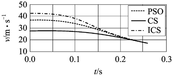
Figure 21.
Comparison of trajectory optimization results for PSO, CS, and ICS. Reprinted with permission from Ref. [74]. Copyright 2019, Wu Y. Et al.
To achieve real-time coordination between deformation and flight, Yun designed an integrated deformation-flight controller that unifies deformation commands and flight control commands. Closed-loop control is realized using state feedback. Applied to a bionic “kingfisher”, this controller achieved attitude control error ≤ 0.6° and deformation position error ≤ 0.5 mm during wing folding, enabling precise coordination.
For future intelligent operational needs, Zhen introduced RL technology, training an agent to learn deformation and flight coordination strategies autonomously. In simulation, after 1000 training episodes, the agent could autonomously select deformation sequences and flight control parameters under complex sea conditions, thereby increasing the aircraft’s medium transition success rate from 70% to 92%. This technology offers a new direction for the autonomous control of FUD, although challenges remain, such as insufficient training samples and difficulties in real-world transfer [75].
4.3. Strong Disturbance Control Algorithms
Folding-wing FUDs are subject to strong disturbances, including water-entry impact, cavitation collapse, wave interference, and sea winds, which are influenced by various uncertainties. The forces and moments exerted on FUD by these factors have a significant impact on its motion posture and trajectory. Traditional PID control algorithms struggle to meet stability requirements, necessitating high-robustness control algorithms [76,77].
ADRC is currently the mainstream choice, whose core lies in using an ESO to estimate disturbances and compensate in real-time. Wang applied ADRC to the water-exit attitude control of submarine-launched missiles [78]. The ESO estimated water-entry impact disturbances with a maximum disturbance of 500 N within 0.1 s and, through compensation control, limited water-exit attitude fluctuations to ≤0.5°, far superior to the 2° fluctuations of traditional PID control. In 2022, Harbin Engineering University combined ADRC with neural networks, utilizing online neural network optimization of ADRC parameters to reduce the disturbance estimation error from 8% to 3%, thereby further enhancing control precision.
To address parameter uncertainties arising from morphing structures, Yang proposed an LPV control algorithm that represents the dynamics model as a linear combination of parameters, achieving stable control under varying parameter values via gain scheduling [79]. This algorithm was applied to the variable-sweep wing control of Beihang University’s bionic “frigatebird”. When the sweep angle was changed from 0° to 60°, the attitude control error remained ≤0.8°, demonstrating its adaptability to parameter variations [80].
For multi-disturbance scenarios involving wave and cavitation interference, Tan proposed a composite algorithm that combines an SMC and a disturbance observer [81]. SMC ensures system robustness to disturbances, while the disturbance observer estimates disturbances in advance to reduce chattering. Tests showed that under combined disturbances of 1 m wave height and cavitation collapse, this algorithm stabilized the pitch angle within ±1°, with a 50% reduction in chattering amplitude compared to traditional SMC.
5. Experimental Verification Technology
The technical maturity of the folding-wing FUD requires experimental verification. The experimental content covers component performance testing, single-machine multimedia testing, and cluster collaborative testing. The core challenges lie in simulating real transmedia environments, precisely measuring dynamic parameters, and reproducing complex sea condition disturbances. Currently, a three-level experimental system comprising laboratory testing, lake/sea trials, and practical drills has been established for both FUDs.
5.1. Laboratory Testing Techniques
Laboratory testing is primarily used for verifying component performance and conducting fundamental theoretical research. Commonly used equipment includes wind tunnels, water tunnels, and impact test benches, which can precisely control the test environment parameters, such as flow rate, pressure, and temperature.
- Wind Tunnel Test: The airfoil of the “flyfish” was evaluated in a low-speed wind tunnel by Park at wind speeds ranging from 0 to 50 m/s [82]. They measured aerodynamic loads using a six-component balance and analyzed the surface flow field of the wing with PIV. The results indicated that the lift-to-drag ratio of the flyfish-inspired airfoil reached 12.5, which is 30% higher than that of the traditional NACA 0012 airfoil, thereby providing valuable data for wing design.
- Water Tunnel Test: The water tunnel tests were conducted to assess the hydrodynamic performance underwater, including resistance, propulsion efficiency, and cavitation characteristics. Lock evaluated the underwater propulsion capabilities in a circulating water tunnel, operating at flow rates of 0 to 10 m/s [83]. Strain sensors were employed to measure the hydrodynamics of the wing surface, offering insights for the design of propulsion systems. In 2022, Harbin Engineering University examined the cavitation characteristics of the Hybrid Autonomous Aerial Vehicle (FUD) in a cavitation water tunnel with pressures ranging from 0 to 0.5 MPa. By capturing images of cavitation bubble morphology with high-speed cameras, they discovered that cavitation bubbles began to form at the nose of the FUD when the underwater speed exceeded 4 m/s, thus providing a design benchmark for the maximum allowable underwater speed [84].
- Impact Bench Test: The impact bench test replicates the conditions of water entry impact and assesses the structural impact resistance. Beihang University performed a simulation of the water entry process for a bobby aircraft using a drop weight impact test bench with velocities ranging from 0 to 20 m/s. They recorded the impact load utilizing an acceleration sensor and assessed the structural stress through a strain gauge. The findings revealed that employing a gradient curvature design for the nose resulted in a 25% reduction in peak impact acceleration. Furthermore, the maximum stress within the structure was maintained at less than 60% of the material’s yield strength, confirming the efficacy of the impact-resistance design.
5.2. Lake/Sea Trial Technology
Lake/sea trials are experimental phases that simulate real-world environments and are used to verify aircraft performance throughout the entire mission cycle, including flight in the air, entry into water, underwater navigation, exit from water, and to address issues such as environmental monitoring, data transmission, and emergency recovery.
In 2022, Harbin Engineering University conducted a comprehensive test of the “Longbow 2” in Songhua Lake, with the Songhua Lake and Qingdao Sea areas serving as the primary test sites in China (see Figure 22). It deployed a meteorological station for monitoring wind speed and direction, a sonar array for monitoring underwater trajectories, and an optical measurement system for tracking air trajectories, achieving a cruise speed of 120 km/h. The parameter measurements for the entire stage, including 120 min of endurance, water surface taxiing 50 m in distance, 15 km/h, underwater diving 30 m in depth, 3 m in speed, and take-off after water release 25 km/h, showed that the performance of the FUD at each stage met the design indicators. The water release success rate reached 98%.
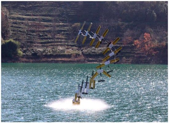
Figure 22.
“Longbow 2” full-process test. Reprinted with permission from Ref. [40]. Copyright 2024, Wang B.X.
North Carolina State University tested the Marine environmental adaptability of FUD in the waters off Hawaii, focusing on verifying their performance under high-sea conditions with a wave height of 1.5 m. The test results show that, through the wave-adaptive control algorithm, FUD has a flight attitude angle fluctuation of no more than 2° in the air and a trajectory deviation of no more than 5 m underwater, meeting the operational requirements for complex Marine environments [85].
Imperial College London conducted an AquaMAV effluent test in the North Sea. Using underwater pressure sensors and high-speed cameras, the effluent velocity and bubble morphology were measured, verifying the feasibility of the CO2 water-jet propulsion scheme [86].
Emergency recovery technology during lake/sea trials is key to ensuring test safety, especially for valuable prototypes. In 2021, Beihang University developed a dual-mode recovery system for parachute landing. When the FUD malfunctions, it automatically opens the parachute in the air or the inflatable float bag on the water surface/underwater to ensure the smooth recovery of the prototype. During the “Flying Fish” prototype test of this system, faulty prototypes were successfully recovered three times, resulting in a 100% recovery rate.
5.3. Cluster Collaborative Test
Cluster collaborative experiments have emerged as a promising new research direction, necessitating the verification of multi-machine communication collaboration, task allocation efficiency, and anti-interference capabilities [87,88].
Mao conducted a cluster test involving four FUDs over Poyang Lake, utilizing a distributed control architecture [89]. Each FUD was equipped with a blue-green laser communication module, boasting a transmission rate of 1 Mbps and an operational range of 5 km, which facilitated data sharing among the vehicles. By employing a cluster task allocation algorithm, the time from target detection to execution was reduced to just 5 min—three times more efficient than a single FUD operating alone. During this test, simulated enemy electromagnetic interference was introduced. However, thanks to frequency-hopping communication technology, the interruption time for cluster communication remained below 10 s, thereby validating the system’s anti-interference capabilities.
In 2023, the US DARPA conducted a swarm test involving 10 “Blackwing” intermediate loitering missiles off the coast of California. This test focused on verifying the coordination capabilities between submarine-launched swarms and their ability to remain concealed underwater. Throughout the experiment, the 10 Lovecraft missiles were sequentially launched from the submarine’s tubes, forming a clustered formation in the air with a spacing of 500 m between them. They conducted coordinated reconnaissance and simulated strikes on target vessels located 10 km away. Notably, this entire process was executed autonomously, without human intervention, marking a significant advancement in the practical verification of cross-media cluster technology in combat.
6. Application Scenarios and Development Trends of Folding-Wing FUD
6.1. Typical Application Scenarios
The Folding-wing FUD, with its dual advantages of low-altitude, high-speed penetration and underwater, concealed maneuvering, has precise applications in both military and civilian fields. Typical scenarios are as follows:
Cross-media reconnaissance and strike: The “Longbow 2” is capable of carrying electro-optical reconnaissance payloads, conducting aerial cruise reconnaissance, and deploying light torpedoes for covert underwater strikes. Following takeoff from its base, it performs a low-altitude penetration into the target maritime area, then submerges nearby to evade radar detection. After launching its attack, it exits the water. The United States plans to upgrade the “AquaMAV” to a loitering missile fitted with a 0.5 kg warhead (see Figure 23), enhancing its ability for cluster penetration and precise strikes. In Mao’s proposed cluster scheme, a three-dimensional control network for aerial cruise is established, enabling target monitoring through a combination of multi-source sensors, including radar, sonar, and electro-optical systems [90].
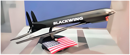
Figure 23.
“Black Wing” loitering missile. Reprinted with permission from Ref. [91]. Copyright 2013, Majumdar D.
- Marine Resource Exploration: FUD is utilized for the exploration of deep-sea minerals, as well as oil and gas resources. It can transport payloads such as magnetometers and side-scan sonar, enabling it to cover extensive areas of ocean at high cruising speeds quickly. Once potential resource areas are identified, the process can seamlessly transition to submersible navigation, allowing for the measurement of resource parameters, including ore layer thickness and the reserves of oil and gas, at close range. Compared to traditional exploration vessels, FUD’s efficiency is ten times greater, while costs are reduced by 50%. Harbin Engineering University has adapted the “Longbow 2” into an exploration platform and has conducted oil and gas exploration trials in the South China Sea.
- Disaster Rescue: In the event of disasters such as typhoons, tsunamis, or shipwrecks, FUD can execute search and rescue operations. For example, it can navigate at low altitudes through affected areas and, upon identifying individuals in distress, enter the water for underwater navigation. Using sonar technology, it can pinpoint the locations of people in need and deploy lifesaving equipment, such as lifebuoys and emergency communication devices. Additionally, FUD can function as a communication relay, establishing an air-to-sea connection to link rescue workers with those affected. In 2023, during a rescue drill for a typhoon disaster in Fujian, Central South University successfully located three individuals in distress using FUD.
- Environmental Monitoring: FUD is also employed for monitoring environmental issues, including marine pollution and red tides (see Figure 24). It can carry payloads such as water quality sensors and spectrometers, allowing it to cruise through the air and assess the extent of pollution. Upon entering the water, it collects samples and analyzes the concentration of contaminants, such as oil and heavy metals, in real time, transmitting this data back to the ground station. The prototype of Beihang University’s “Flying Fish” has been utilized to monitor oil pollution in the Bohai Sea, achieving significantly broader coverage than traditional monitoring buoys.
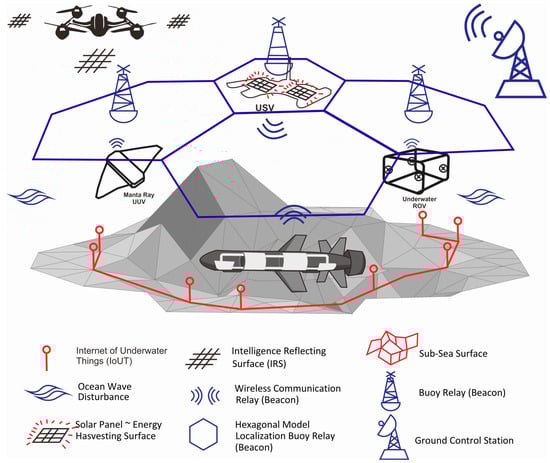 Figure 24. Scenario joint-operation. Reprinted with permission from Ref. [92]. Copyright 2018, Alzu’bi H. et al.
6.2. Technological Development Trends
Considering the current research bottlenecks and application demands, the future development of folding-wing FUDs is expected to progress along three main trajectories: intelligence, clustering, and integration. The key technological breakthroughs supporting these directions are as follows:
- Advanced Materials and Intelligent Morphing Structures: Future developments will focus on the synthesis of impact-resistant and anti-cavitation composite materials for critical components like the nose cone, while utilizing SMP for adaptive wing structures. The convergence of adaptive deformation technology, flexible material stiffness adjustment, and multimodal cooperative perception will enable the vehicle to reconfigure its shape in response to its surroundings autonomously. This capability will allow the dynamic optimization of deformation parameters, thereby maximizing aerodynamic lift during flight and minimizing hydrodynamic drag during underwater navigation [93].
- Cluster Collaboration and Intelligent Decision-Making: The introduction of deep learning algorithms, combined with advanced dynamic task allocation protocols, will significantly enhance the autonomous decision-making capabilities of FUDs in complex marine environments and adversarial scenarios. This intelligence will extend to robust multi-vehicle collaboration, improving resilience against jamming and enabling real-time, optimized task distribution within a cluster. Initiatives like the U.S. DARPA’s program, which aims to demonstrate autonomous decision-making for cross-media loitering munitions by 2026, underscore the strategic importance of this trend.
- Novel Propulsion and Energy Systems: To break the endurance bottleneck, innovations in power and propulsion are essential. Efforts will focus on enhancing energy density and optimizing the integration of air-water dual-purpose propulsion systems. A key breakthrough will be the development of multi-fuel compatible combustion chambers, capable of efficiently utilizing conventional aviation kerosene in the air and initiating reactions such as aluminum-water combustion underwater, thus reducing system complexity. Furthermore, energy harvesting technologies will be crucial. This includes deploying piezoelectric ceramics on the vehicle’s nose to convert water impact energy into electricity and integrating flexible piezoelectric films on wing surfaces to harvest energy from flow-induced vibrations. As evidenced by Beihang University’s plan to implement such energy recovery technologies in an upgraded “Flying Fish” prototype by 2026, which is projected to increase underwater endurance by 20%, these innovations are poised to extend mission durations significantly [94].
7. Conclusions and Prospects
This review highlights significant advancements in folding-wing FUDs, which tackle the challenging task of seamless operation across air and water boundaries. By systematically examining overall layout design, propulsion systems, dynamics, control mechanisms, and experimental verification, we delineate the current state of the art and identify ongoing challenges [95].
The development of morphing structures, inspired by natural organisms such as flying fish and kingfishers, has led to two primary folding paradigms: lateral and longitudinal folding. Each paradigm presents distinct trade-offs in performance, complexity, and spatial efficiency. In the realm of propulsion, the differentiation between integrated dual-use systems and reliable hybrid systems continues to define design trade-offs, with neither providing a fully optimal solution. Importantly, modeling and controlling complex multiphase flow during transitions between media remains a core scientific challenge, requiring advanced FSI simulations and robust control algorithms to ensure stability. The establishment of a comprehensive three-level experimental verification system illustrates the field’s maturity as it moves from benchtop tests to successful open-water and cluster trials.
Despite these accomplishments, critical bottlenecks remain. Restrictions such as limited underwater endurance, structural fatigue from repeated folding and impact loads, and unresolved compromises in propulsion system integration continue to hinder widespread deployment. Looking ahead, a truly interdisciplinary approach will be necessary. Key breakthroughs are likely to emerge from the development of intelligent morphing structures utilizing advanced composites and shape-memory polymers, as well as the integration of artificial intelligence and deep learning for autonomous decision-making and effective cluster collaboration. Innovations in multi-fuel propulsion and energy-harvesting systems are also expected to overcome existing limitations and unlock the full operational potential of FUDs in cross-domain missions.
The potential applications for FUDs are vast, spanning cross-domain reconnaissance, precision strikes, marine resource exploration, environmental monitoring, and disaster rescue. These applications promise significant impacts on national security and socio-economic development. As the technology evolves from principle validation to engineering application, collaboration among academia, research institutions, and industry will be essential to address the remaining challenges. With continuous innovation, folding-wing FUDs are anticipated to evolve into intelligent, long-endurance, and collaborative systems across multiple domains, ultimately becoming indispensable components of our future technological landscape.
Author Contributions
Conceptualization, J.T. and W.G.; methodology, H.C. and W.G.; investigation, H.Z. and C.Z.; data curation, H.Z. and C.Z.; writing—original draft preparation, J.T., W.G. and J.Z.; writing—review and editing, J.Z. and J.T.; visualization, J.Z. and J.T.; supervision, H.C. and W.G.; All authors have read and agreed to the published version of the manuscript.
Funding
This research was funded by the GANWEI action plan project (grant number GW2025-46, WZ2024-2-14), the National Natural Science Foundation of China (grant numbers U2141252, U2141249, 11902018, 92471205), the Hainan key research and development program (grant number ZDYF2025SHFZ059), the Open Funding of National Key Laboratory of Digital and Agile Aircraft Design (grant numbers KFJJ--2024-I-01-01), and the Open Research Fund of Yunnan Technology Innovation Center of Low-Altitude Economy and UAV.
Data Availability Statement
No new data were created or analyzed in this study. Data sharing does not apply to this article.
DURC Statement
Current research is limited to the design and engineering implementation technologies for Folding-wing FUD, which are beneficial for enhancing the efficiency and adaptability of tasks, including cross-domain reconnaissance, marine resource exploration, and disaster rescue, and do not pose a threat to public health or national security. The authors acknowledge the dual-use potential of the research involving the FUD system and confirm that all necessary precautions have been taken to prevent potential misuse. As an ethical responsibility, authors strictly adhere to relevant national and international laws about DURC. Authors advocate for responsible deployment, ethical considerations, regulatory compliance, and transparent reporting to mitigate misuse risks and foster beneficial outcomes.
Conflicts of Interest
The authors declare that they have no conflicts of interest.
Abbreviations
The following abbreviations are used in this manuscript:
| FUD | Flying Underwater Drone |
| ANN | Artificial Neural Network |
| ML | Machine Learning |
| CFD | Computational Fluid Dynamics |
| SMA | Shape Memory Alloy |
| CVT | Continuously Variable Transmission |
| VOF | Volume of Fluid |
| PI | Proportional-Integral |
| 6-DOF | Six-Degree-Of-Freedom |
| ADRC | Active Disturbance Rejection Control |
| ESO | Extended State Observer |
| LPV | Linear Parameter-Varying |
| SMC | Sliding Mode Control |
| RL | Reinforcement Learning |
| PIV | Particle Image Velocimetry |
| SMP | shape memory polymers |
| FSI | fluid–structure interaction |
| DARPA | Defense Advanced Research Projects Agency |
References
- Qi, H.; Hu, S.; Zhang, J.; Wu, G. Review of Hybrid Aerial Underwater Vehicle: Potential Applications in the Field of Underwater Marine Optics. Drones 2025, 9, 667. [Google Scholar] [CrossRef]
- Geder, J.D.; Ramamurti, R.; Edwards, D.; Sandberg, W.; Mueller, T. Swimming Performance of a Hybrid Unmanned Air-Underwater Vehicle. In Proceedings of the OCEANS 2016 MTS/IEEE Monterey, Monterey, CA, USA, 19–23 September 2016; pp. 1–5. [Google Scholar]
- Crouse, G. Conceptual Design of a Submersible Airplane. In Proceedings of the 48th AIAA Aerospace Sciences Meeting Including the New Horizons Forum and Aerospace Exposition, Orlando, FL, USA, 4–7 January 2010. [Google Scholar]
- Di Luca, M.; Mintchev, S.; Su, Y.X.; Shaw, E.; Breuer, K. A Bioinspired Separated Flow Wing Provides Turbulence Resilience and Aerodynamic Efficiency for Miniature Drones. Sci. Robot. 2020, 5, eaay8533. [Google Scholar] [CrossRef]
- Jiao, J.; Chen, C.; Wang, B.; Ying, P.; Wei, Q.; Nie, S. Active Flow Control Technology Based on Simple Droop Devices and a Co-Flow Jet for Lift Enhancement. Aerospace 2025, 12, 198. [Google Scholar] [CrossRef]
- Panta, A.; Marino, M.; Fisher, A.; Mohamed, A.; Watkins, S. Exploring the Impact of Rapidly Actuated Control Surfaces on Drone Aerodynamics. Drones 2023, 7, 494. [Google Scholar] [CrossRef]
- Abdolahipour, S. Review on Flow Separation Control: Effects of Excitation Frequency and Momentum Coefficient. Front. Mech. Eng. 2024, 10, 1380675. [Google Scholar] [CrossRef]
- Ramamurti, R.; Geder, J.D.; Edwards, D.; Palmisano, J.; Sandberg, W.C.; Nadira, A. Computational Studies for the Development of a Hybrid UAV/UUV. In Proceedings of the 33rd AIAA Applied Aerodynamics Conference, Dallas, TX, USA, 22–26 June 2015; p. 2414. [Google Scholar]
- Mathaiyan, V.; Vijayanandh, R.; Senthil, K.; Ramesh, M. Conceptual Design and Numerical Analysis of an Unmanned Amphibious Vehicle. In Proceedings of the AIAA Scitech 2021 Forum, Virtual Event, 11–15, 19–21 January 2021; p. AIAA 2021-1285. [Google Scholar]
- Paulo, L.J.; Armando, A.; Mario, F.M. A Survey on Aerial Submersible Vehicles. In Proceedings of the IEEE/OES Oceans, Bremen, Germany, 11–14 May 2009; pp. 1–7. [Google Scholar]
- Trdnt, Y.; Jason, G.; Dan, E. Flimmer: A Flying Submarine; Naval Research Laboratory SPECTRA: Washington, DC, USA, 2015. [Google Scholar]
- Petrov, G. Flying Submarine. Fleet 1995, 3, 52–53. [Google Scholar]
- Yao, G.C.; Li, Y.Z.; Zhang, H.Y.; Wang, T.M.; Liang, J.H. Review of Hybrid Aquatic-Aerial Vehicle (HAAV): Classifications, Current Status, Applications, Challenges and Technology Perspectives. Prog. Aerosp. Sci. 2023, 139, 100902. [Google Scholar] [CrossRef]
- Feng, J.F.; Hu, J.H.; Qi, D. Development Requirements and Key Technologies of Water-Air Cross-Domain Vehicles. J. Air Force Eng. Univ. Nat. Sci. Ed. 2019, 20, 8–13. (In Chinese) [Google Scholar]
- Zhang, C.Y.; Yang, F.; Liu, K.; Wang, J.H.; Li, W. Development and Key Technology Analysis of Reconfigurable Cross-Domain Aircraft. Astron. Syst. Eng. Technol. 2021, 5, 54–61, 72. (In Chinese) [Google Scholar]
- Yang, Y.X.; Duan, Y.J.; Huang, L.K.; Li, J.; Wang, Z.T. Development Concept of Combined Power Technology for Air/Water Cross-Domain Equipment. J. Propuls. Technol. 2020, 41, 2237–2244. (In Chinese) [Google Scholar]
- Hou, T.G.; Jin, D.Z.; Gong, Y.D.; Wang, J.H.; Li, Y. Advances in Frontier Technologies of Water-Air Cross-Domain Vehicles. Sci. Technol. Rev. 2023, 41, 5–22. (In Chinese) [Google Scholar]
- Li, C.; Lyu, R.Y.; Qian, R.J.; Li, Z.Y.; Wang, Z. Research on the Development and Application of U.S. Cross-Domain Vehicle Technology. Tactical Missile Technol. 2023, 6, 120–127. (In Chinese) [Google Scholar]
- Margulis, M.; Blaise, P.; Stimpson, S.; Graham, A.; Collins, B. Development of a Coupled Subplane Capability in Mpact. EPJ Web Conf. 2021, 247, 06051. [Google Scholar] [CrossRef]
- Liu, X.; Dou, M.; Huang, D.; Gao, S.; Yan, R.; Wang, B.; Cui, J.; Ren, Q.; Dou, L.; Gao, Z.; et al. TJ-FlyingFish: Design and Implementation of an Aerial-Aquatic Quadrotor with Tiltable Propulsion Units. In Proceedings of the 2023 IEEE International Conference on Robotics and Automation (ICRA), London, UK, 29 May–2 June 2023; pp. 7324–7330. [Google Scholar] [CrossRef]
- Liu, X.; Dou, M.; Yan, R.; Huang, D.; Gao, S.; Wang, B.; Cui, J.; Ren, Q.; Dou, L.; Gao, Z.; et al. TJ-FlyingFish: An Unmanned Morphable Aerial–Aquatic Vehicle System. Unmanned Syst. 2024, 12, 409–428. [Google Scholar] [CrossRef]
- Liu, K.; Xiao, J.; Lin, H.; Cao, Y.; Peng, H.; Huang, K.; Lu, H. SurfAAV: Design and Implementation of a Novel Multimodal Surfing Aquatic-Aerial Vehicle. J. Field Robot. 2025, 39, 1–15. [Google Scholar] [CrossRef]
- Lyu, C.; Lu, D.; Xiong, C.; Hu, R.; Jin, Y.; Wang, J.; Zeng, Z.; Lian, L. Toward a Gliding Hybrid Aerial Underwater Vehicle: Design, Fabrication, and Experiments. J. Field Robot. 2022, 39, 543–556. [Google Scholar] [CrossRef]
- Moore, J.; Fein, A.; Setzler, W. Design and Analysis of a Fixed-Wing Unmanned Aerial-Aquatic Vehicle. In Proceedings of the 2018 IEEE International Conference on Robotics and Automation (ICRA), Brisbane, Australia, 21–25 May 2018; pp. 1236–1243. [Google Scholar]
- Weisshaar, T.A. Morphing Aircraft Systems: Historical Perspectives and Future Challenges. J. Aircr. 2013, 50, 337–353. [Google Scholar] [CrossRef]
- Erbil, M.A.; Prior, S.D.; Karamanoglu, M.; Knight, G. Reconfigurable Unmanned Aerial Vehicles. In Proceedings of the International Conference on Manufacturing and Engineering Systems, Istanbul, Turkey, 16–18 December 2009; pp. 392–396. [Google Scholar]
- Yang, X.B.; Liang, J.H.; Wen, L.; Wang, T.M. Research Status of Water-Air Amphibious Cross-Domain Unmanned Aerial Vehicles. Robot 2018, 40, 102–114. (In Chinese) [Google Scholar] [CrossRef]
- Müller, R.; Abaid, N.; Boreyko, J.B.; Fowlkes, C.; Gardner, A.; Gorb, S.; Kim, S.; Kovač, M.; Lee, S.H.; López, R.; et al. Biodiversifying Bioinspiration. Bioinspir. Biomim. 2018, 13, 053001. [Google Scholar] [CrossRef]
- Davenport, J. How and Why Do Flying Fish Fly? Rev. Fish Biol. Fish. 1994, 4, 184–214. [Google Scholar] [CrossRef]
- Deng, J.; Zhang, L.X.; Liu, Z.Y.; Liu, Y.G.; Wu, Z. Numerical Prediction of Aerodynamic Performance for a Flying Fish during Gliding Flight. Bioinspir. Biomim. 2019, 14, 046009. [Google Scholar] [CrossRef]
- Hu, J.H.; Xu, B.W.; Feng, J.F.; Qi, D. Research on Water-Exit and Take-Off Process for Morphing Unmanned Submersible Aerial Vehicle. China Ocean Eng. 2017, 31, 202–209. [Google Scholar] [CrossRef]
- Huang, X.T.; Sun, P.N.; Zhang, A.M. Water Entry Problems Simulated by an Axisymmetric SPH Model with VAS Scheme. J. Mar. Sci. Appl. 2022, 21, 1–15. [Google Scholar] [CrossRef]
- Yang, X.B.; Wang, T.M.; Liang, J.H.; Yao, G.C.; Li, Y.M. Numerical Analysis of Biomimetic Gannet Impacting with Water during Plunge-Diving. In Proceedings of the 2012 IEEE International Conference on Robotics and Biomimetics (ROBIO), Guangzhou, China, 11–14 December 2012; pp. 569–574. [Google Scholar]
- Liu, H.X. Research on the Mechanism of Bionic Cross-Media Vehicle and Prototype Engineering. Ph.D. Thesis, Beihang University, Beijing, China, 2009. (In Chinese) [Google Scholar]
- Fabian, A.; Feng, Y.F.; Swartz, E.; Ratti, J.; Tricaud, C.; Baillieul, J.; Sabet, S. Hybrid Aerial Underwater Vehicle; MIT Lincoln Lab: Lexington, MA, USA, 2012. [Google Scholar]
- Liang, J.H.; Yang, X.B.; Wang, T.M.; Yao, G.C.; Li, Y.M. Design and Experiment of a Bionic Gannet for Plunge-Diving. J. Bionic Eng. 2013, 10, 282–291. [Google Scholar] [CrossRef]
- Yang, X.B.; Wang, T.M.; Liang, J.H.; Yao, G.C.; Li, Y.M. Submersible Unmanned Aerial Vehicle Concept Design Study. In Proceedings of the AIAA Aviation Technology, Integration, and Operations Conference, Los Angeles, CA, USA, 12–14 August 2013; p. 4422. [Google Scholar]
- Siddall, R.; Kovač, M. Fast Aquatic Escape with a Jet Thruster. IEEE/ASME Trans. Mechatron. 2017, 22, 217–226. [Google Scholar] [CrossRef]
- Armanini, S.F.; Siddall, R.; Kovac, M. Modelling and Simulation of a Bioinspired Aquatic Micro Aerial Vehicle. In Proceedings of the AIAA Aviation 2019 Forum, Dallas, TX, USA, 17–21 June 2019; p. 3115. [Google Scholar]
- Wang, B.X. Research on Motion Control of a Folding-Wing Cross-Domain Vehicle. Master’s Thesis, Harbin Engineering University, Harbin, China, 2024. (In Chinese) [Google Scholar] [CrossRef]
- Zhu, S. The Design and Research of Power System in Water-Air UAV. Master’s Thesis, Nanchang Hangkong University, Nanchang, China, 2012. (In Chinese) [Google Scholar]
- Yun, Z.; Chen, L.; Luo, Z.R.; Shang, J.Z. Numerical Simulation of Fluid Dynamics of Variable-Sweep Wing of Cross-Media Vehicle Based on Sarrus Mechanism. J. Mach. Des. 2019, 36, 15–20. (In Chinese) [Google Scholar]
- Tan, Y.H.; Chen, B.M. Design of a Morphable Multirotor Aerial-Aquatic Vehicle. In Proceedings of the OCEANS 2019 MTS/IEEE Marseille, Marseille, France, 17–20 June 2019; pp. 1–8. [Google Scholar]
- Shan, R.L. Research on Optimization Design and Experimental Method of Water-Air Dual-Purpose Propeller. Master’s Thesis, Shanghai Jiao Tong University, Shanghai, China, 2021. (In Chinese) [Google Scholar] [CrossRef]
- Li, P.F.; Huang, L.Y.; Xia, Z.X.; Liu, Y.; Tian, A. Research on the Working Characteristics of a Boron-Based Fuel-Rich Propellant Cross-Domain Ramjet. J. Solid Rocket Technol. 2022, 45, 662–667. (In Chinese) [Google Scholar]
- Schneider, S.J. Hydrogen Peroxide-Water-Ethanol Monopropellant Blend for CubeSat Propulsion. In Proceedings of the AIAA Propulsion and Energy 2020 Forum, Virtual Event, 24–28 August 2020; p. 3809. [Google Scholar]
- Zufferey, R.; Ancel, A.O.; Farinha, A.; Siddall, R.; Armanini, S.F.; Mange, R.; Stewart, W.J.; Kovac, M. Consecutive Aquatic Jump-Gliding with Water-Reactive Fuel. Sci. Robot. 2019, 4, eaax7330. [Google Scholar] [CrossRef]
- Wu, J.M.; Yang, Y.X.; Wang, Z.T.; Li, J.; Zhang, H. Research Status and Prospects of Propellant Feeding for Powder Engines. J. Aerosp. Power 2024, 39, 219–228. (In Chinese) [Google Scholar]
- Liu, P.A.; Chang, H.; Li, S.S.; Wang, J.; Zhang, L. Numerical Simulation of Distributed Combustion of the Aluminized Composite Propellant. J. Solid Rocket Technol. 2018, 41, 156–161, 168. (In Chinese) [Google Scholar]
- Whitmore, S.A.; Merkley, D.P. Arc-Ignition of a 70%–85% Hydrogen Peroxide/ABS Hybrid Rocket System. In Proceedings of the 53rd AIAA/SAE/ASEE Joint Propulsion Conference, Atlanta, GA, USA, 10–12 July 2017; p. 5047. [Google Scholar]
- Chen, W.W.; Huang, L.Y.; Xia, Z.X.; Liu, Y.; Tian, A. Theoretical Performance and Working Parameters Analysis of Trans-Medium Ramjet. Acta Aeronaut. Astronaut. Sin. 2020, 41, 197–206. (In Chinese) [Google Scholar]
- Yang, X.B.; Pei, X. Hybrid System for Powering Unmanned Aerial Vehicles: Demonstration and Study Cases. In Hybrid Technologies for Power Generation; Academic Press: Cambridge, MA, USA; Elsevier: Amsterdam, The Netherlands, 2022; pp. 439–473. [Google Scholar]
- Rendón, M.A.; Josselyn, G.M.; Smith, H.; Jones, P. Aircraft Hybrid-Electric Propulsion: Development Trends, Challenges and Opportunities. J. Control Autom. Electr. Syst. 2021, 32, 1244–1268. [Google Scholar] [CrossRef]
- Cong, M. Cormorant Submarine-Launched Multi-Purpose UAV Completes Splashdown and Recovery Test. Winged Missile J. Feihang Daodan 2007, 5, 25–26. (In Chinese) [Google Scholar]
- Stewart, W.; Weisler, W.; MacLeod, M.; Anderson, M.B.; DeVries, L.; Epps, B.; Lentink, D. Design and Demonstration of a Seabird-Inspired Fixed-Wing Hybrid UAV-UUV System. Bioinspir. Biomim. 2018, 13, 056013. [Google Scholar] [CrossRef]
- Siddall, R.; Kovač, M. Launching the AquaMAV: Bioinspired Design for Aerial–Aquatic Robotic Platforms. Bioinspir. Biomim. 2014, 9, 031001. [Google Scholar] [CrossRef] [PubMed]
- Siddall, R.; Kovač, M. A Water Jet Thruster for an Aquatic Micro Air Vehicle. In Proceedings of the 2015 IEEE International Conference on Robotics and Automation (ICRA), Seattle, WA, USA, 26–30 May 2015; pp. 3979–3985. [Google Scholar]
- Tang, Y.L.; Li, S.P.; Liu, Z.; Wang, Y.; He, B. Thrust Characteristics of Underwater Solid Rocket Motors. J. Aerosp. Power 2017, 32, 477–485. (In Chinese) [Google Scholar]
- Tang, S.J.; Zhang, B.C.; Yue, C.H.; Guo, J.J. Analysis of Key Technologies and Research Trends of Flight Dynamics for Cross-Domain Vehicles. Winged Missile J. Feihang Daodan 2011, 6, 7–13. (In Chinese) [Google Scholar]
- Wang, C.; Xu, H.Y.; Ma, G.H.; Li, H.Y.; Yan, J.Y. Research Progress on Frontier Technologies of Dynamics for Cross-Domain Vehicles. J. Unmanned Undersea Syst. 2024, 32, 384–395. (In Chinese) [Google Scholar]
- Wang, C.; Xu, H.Y.; Lu, J.X. Research Status and Prospects of Multiphase Flow Field and Motion Characteristics during Water Entry of Cross-Domain Vehicles. J. Unmanned Undersea Syst. 2023, 31, 38–49. (In Chinese) [Google Scholar]
- Siddall, R.; Kennedy, G.; Kovac, M. High-Power Propulsion Strategies for Aquatic Take-Off in Robotics. In Springer Proceedings in Advanced Robotics; Springer: Cham, Switzerland, 2017; Volume 3, pp. 5–20. [Google Scholar]
- Liu, Y.; Wu, Z.L.; Tan, H.J. Related Technologies and Analysis of Cross-Domain Aircraft. Aviat. Power 2024, 2, 13–16. (In Chinese) [Google Scholar]
- Bang, C.S.; Rana, Z.A.; Könözsy, L.; Marchante Rodriguez, V.; Temple, C. Numerical Investigation and Fluid-Structure Interaction (FSI) Analysis on a Double-Element Simplified Formula One (F1) Composite Wing in the Presence of Ground Effect. Fluids 2022, 7, 85. [Google Scholar] [CrossRef]
- Wang, Y.; Bai, X.Z.; Zhang, D.X.; Lin, Z.C.; Fan, Z.L.; Wu, W.H. Experimental Research on the Aerodynamic Characteristics of the Near-Water Effect of Multi-Rotor. Acta Aeronaut. Astronaut. Sin. 2025, 46, 32234. (In Chinese) [Google Scholar] [CrossRef]
- Qu, Q.L.; Liu, P.Q.; Qin, X.G. Numerical Research on Aerodynamic Characteristics of WIG Craft Flying over Wavy Ground. Acta Aeronaut. Astronaut. Sin. 2007, 28, 1327–1333. (In Chinese) [Google Scholar]
- Du, T.Z.; Huang, R.F.; Wang, C. Simulation Analysis of Fluid-Structure Interaction for Cavitating Flow Around Elastic Rudder Wings of Cross-Domain Vehicles. Astron. Syst. Eng. Technol. 2020, 4, 28–33. (In Chinese) [Google Scholar]
- Huang, Z.G.; Fan, H.W.; Chen, Z.H.; Hou, Y.; Li, J. Numerical Simulation Study on the Mechanism and Characteristics of High-Speed Water Entry of Hollow Projectile. Explos. Shock Waves 2024, 44, 117–131. (In Chinese) [Google Scholar]
- Ming, F.R.; Wang, J.J.; Liu, W.T.; Liu, X.J.; Zhang, A.M. Review of Multiphase Flow and Fluid-Structure Interaction of High-Speed Water Entry. Acta Aerodyn. Sin. 2024, 42, 68–85. (In Chinese) [Google Scholar] [CrossRef]
- Guo, T.H.; Hou, Z.X.; Zhu, B.J. Dynamic Modeling and Active Morphing Trajectory-Attitude Separation Control Approach for Gull-Wing Aircraft. IEEE Access 2017, 5, 17006–17019. [Google Scholar] [CrossRef]
- Yu, X.C.; Wang, Z.X.; Tan, W.; Wu, X.Y.; Li, J. A Review of Morphing Technology for Fixed-Wing Hybrid Aerial-Aquatic Vehicles (HAAV). Digit. Ocean Underw. Warf. 2025, 8, 47–53. (In Chinese) [Google Scholar]
- Yu, X.C.; Wang, Z.X.; Tan, W.; Wu, X.Y.; Li, J. Research Progress in Morphing Structure Design Technology for Cross-Domain Vehicles. Acta Aeronaut. Astronaut. Sin. 2024, 45, 231349. (In Chinese) [Google Scholar]
- Shao, D. Power Analysis of Cross-Domain Aircraft. Aviat. Power 2020, 1, 12–15. (In Chinese) [Google Scholar]
- Wu, Y.; Li, L.; Su, X.; Gao, B.W. Dynamics Modeling and Trajectory Optimization for Unmanned Aerial-Aquatic Vehicle Diving into the Water. Aerosp. Sci. Technol. 2019, 89, 220–229. [Google Scholar] [CrossRef]
- Zhen, Y.; Yuan, J.Q.; Chi, Q.X.; Wang, H.L.; Li, P. Research on the Application of Deep Reinforcement Learning Methods in Aircraft Control. Tactical Missile Technol. 2020, 4, 112–118. (In Chinese) [Google Scholar]
- Krawczyk, Z.; Vuppala, R.K.S.S.; Paul, R.; Kara, K. Urban Wind Field Effects on the Flight Dynamics of Fixed-Wing Drones. Drones 2025, 9, 362. [Google Scholar] [CrossRef]
- Abdolahipour, S. Effects of Low and High Frequency Actuation on Aerodynamic Performance of a Supercritical Airfoil. Front. Mech. Eng. 2023, 9, 1290074. [Google Scholar] [CrossRef]
- Wang, Y.J. Research on Attitude Control and Water-Exit Trajectory Optimization Design for Submarine-Launched Missiles. Ph.D. Thesis, Harbin Institute of Technology, Harbin, China, 2017. (In Chinese) [Google Scholar]
- Yang, G.T. Research on Modeling and Control Methods for Morphing Aircraft. Ph.D. Thesis, Beijing Institute of Technology, Beijing, China, 2015. (In Chinese) [Google Scholar]
- Yao, G.; Liang, J.; Wang, T.; Yang, X.; Li, Y. Submersible Unmanned Flying Boat: Design and Experiment. In Proceedings of the 2014 IEEE International Conference on Robotics and Biomimetics (ROBIO 2014), Bali, Indonesia, 5–10 December 2014; pp. 1308–1313. [Google Scholar]
- Tan, J.Y.; Hu, J.H.; Ma, Z.C.; Wang, C.; Li, H.Y. Research on Flight Path Angle Control during the Diving Process of Water-Air Cross-Domain Vehicles. Flight Dyn. 2019, 37, 34–38. (In Chinese) [Google Scholar]
- Park, H.; Choi, H. Aerodynamic Characteristics of Flying Fish in Gliding Flight. J. Exp. Biol. 2010, 213, 3269–3279. [Google Scholar] [CrossRef]
- Lock, R.J.; Vaidyanathan, R.; Burgess, S.C. Design and Experimental Verification of a Biologically Inspired Multi-Modal Wing for Aerial-Aquatic Robotic Vehicles. In Proceedings of the 2012 4th IEEE RAS and EMBS International Conference on Biomedical Robotics and Biomechatronics (BioRob), Rome, Italy, 24–27 June 2012; pp. 681–687. [Google Scholar]
- Siddall, R.; Ortega Ancel, A.; Kovač, M. Wind and Water Tunnel Testing of a Morphing Aquatic Micro Air Vehicle. Interface Focus 2017, 7, 20160085. [Google Scholar] [CrossRef]
- Weisler, W.; Stewart, W.; Anderson, M.B.; DeVries, L.; Epps, B.; Lentink, D. Testing and Characterization of a Fixed Wing Cross-Domain Unmanned Vehicle Operating in Aerial and Underwater Environments. IEEE J. Ocean. Eng. 2018, 43, 969–982. [Google Scholar] [CrossRef]
- Tan, Y.H.; Siddall, R.; Kovac, M. Efficient Aerial-Aquatic Locomotion with a Single Propulsion System. IEEE Robot. Autom. Lett. 2017, 2, 1304–1311. [Google Scholar] [CrossRef]
- Liang, J.H.; Yao, G.C.; Wang, T.M.; Yang, X.B.; Li, Y.M. Wing Load Investigation of the Plunge-Diving Locomotion of a Gannet Morus Inspired Submersible Aircraft. Sci. China Technol. Sci. 2014, 57, 390–402. [Google Scholar] [CrossRef]
- Wang, T.M.; Yang, X.B.; Liang, J.H.; Yao, G.C.; Li, Y.M. CFD Based Investigation on the Impact Acceleration When a Gannet Impacts with Water during Plunge Diving. Bioinspir. Biomim. 2013, 8, 036006. [Google Scholar] [CrossRef]
- Mao, J.Y.; Liu, F.; Wei, Z.P. Key Technologies and Development Trends of Lightweight and Small-Scale Cross-Domain Loitering Munition Clusters. J. Proj. Rocket. Missiles Guid. 2024, 44, 59–65. (In Chinese) [Google Scholar]
- Sun, D.P.; Feng, L.P.; Yan, G.Y. Analysis of the U.S. Military’s Blackwing UAV System and Its Operational Use. Winged Missile J. Feihang Daodan 2020, 9, 57–60. (In Chinese) [Google Scholar]
- Majumdar, D. US Navy Launches UAV from a Submarine. US Naval Inst. News 2013, 2, 31–42. [Google Scholar]
- Alzu’bi, H.; Mansour, I.; Rewashded, O. Loon Copter: Implementation of a Hybrid Unmanned Aquatic-Aerial Quadcopter with Active Buoyancy Control. J. Field Robot. 2018, 35, 764–778. [Google Scholar] [CrossRef]
- Eubank, R.D.; Atkins, E. Unattended Autonomous Mission and System Management of an Unmanned Seaplane. In Proceedings of the Infotech@Aerospace Conferences, St. Louis, MO, USA, 29–31 March 2011; p. AIAA 2011-1614. [Google Scholar]
- Eubank, R.D.; Bradley, J.M.; Atkins, E.M. Energy-Aware Multiflight Planning for an Unattended Seaplane: Flying Fish. J. Aerosp. Inf. Syst. 2017, 14, 73–91. [Google Scholar] [CrossRef]
- Bowman, J.; Sanders, B.; Cannon, B.; Kudva, J.; Joshi, S.; Weisshaar, T. Development of Next Generation Morphing Aircraft Structures. In Proceedings of the 48th AIAA/ASME/ASCE/AHS/ASC Structures, Structural Dynamics, and Materials Conference, Honolulu, HI, USA, 23–26 April 2007; p. 1730. [Google Scholar]


Disclaimer/Publisher’s Note: The statements, opinions and data contained in all publications are solely those of the individual author(s) and contributor(s) and not of MDPI and/or the editor(s). MDPI and/or the editor(s) disclaim responsibility for any injury to people or property resulting from any ideas, methods, instructions or products referred to in the content. |
© 2026 by the authors. Licensee MDPI, Basel, Switzerland. This article is an open access article distributed under the terms and conditions of the Creative Commons Attribution (CC BY) license.