Abstract
We present a two-stage energy extraction circuit for a piezoelectric energy harvester, powering an asset-tracking system. Exploiting non-sinusoidal accelerations generated by many logistic transport devices, e.g., pushcarts, forklifts, assembly belts or cars, we are able to harvest sufficient electrical energy to transmit radio signals, which will allow to track the object when it is moving. By using the proposed energy extraction circuit, the energy extraction efficiency could be improved by at least 30% compared to a single-stage solution for sinusoidal excitations. In the practical use-case, the two-stage energy extraction network performs more than four times better compared to the single staged on.
1. Introduction
Energy Harvesting gets more and more attractive caused by the technological advance in designing low power electronic devices. The energy harvesting technology has to be chosen according to the desired use-case, providing the electrical power demand of the electrical application under the conditions of the considered excitation. [1] The paper is organized as follows: At first, we describe the considered excitation scenario by measuring its accelerations. Furthermore, the electrical power output of a piezoelectric Energy Harvester (Figure 1a) is measured for sinusoidal excitation with respect to both load resistance and frequency. Subsequently, the proposed two-stage electrical energy extraction network is introduced and evaluated under laboratory conditions and for the desired practical use-case (Figure 1b). We conclude by comparing the performances of the single-stage and two- stage approach.

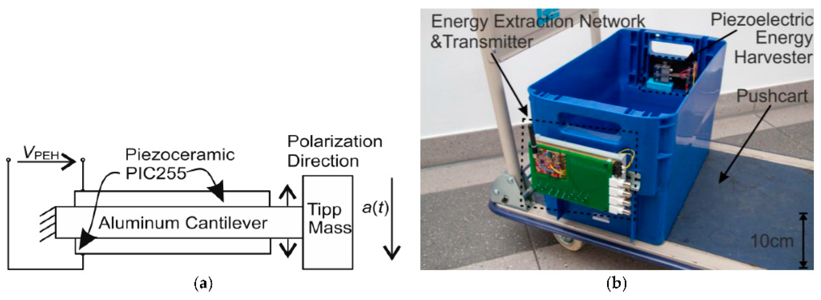
Figure 1.
(a) Piezoelectric energy harvester. (b) Photography of pushcart with container, piezoelectric energy harvester and energy extraction network.
2. Characterization of the Excitation and the Piezoelectric Energy Harvester
To extract the maximum electrical power of piezoelectric energy harvesters (PEH), both the mechanical excitation and the electrical load have to be at the maximum power point of the PEH. The design process relies on finite-element simulations which depend on exact material data obtained by the inverse method. [2] On the one hand, it is essential to characterize the surrounding acceleration power spectrum of the considered use-case to be able to adapt the mechanical side, the resonance frequency, of the PEH accordingly, as depicted Figure 2a. On the other hand, the optimal electrical load has to be connected to the piezoelectric energy harvester to extract the maximum electrical power from it, as shown in Figure 2b.
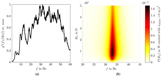
Figure 2.
(a) Power spectrum of measured acceleration. (b) Electrical power output (𝑅𝐿) of the piezoelectric energy harvester at directly connected load resistance 𝑅𝐿 with harmonic excitation frequency 𝑓.
Figure 2a shows the power spectrum of the measured acceleration of a pushcart driving on asphalt street. Though there is no distinct peak frequency detectable, it can be stated that the most surrounding power is at the frequency range between 30 Hz–50 Hz. As depicted in Figure 2b, the resonance frequency of the PEH was designed to be just in this range (33 Hz) and therefore, the PEH can gather the ambient mechanical power. Furthermore, it can be seen that the electrical power output also depends on the load resistance connected to the PEH.
3. Two Stage Energy Extraction Network
In literature [3,4,5], different energy extraction schemes are discussed. Active topologies, like synchronized electrical charge extraction pursue to extract the total electrical charge of 𝐶𝑃𝐸𝐻. This is realized by shortly connecting an inductivity at the maximum open circuit voltage of the PEH. To do this, the maximum of the PEHs open circuit voltage 𝑉𝑃𝐸𝐻,LL has to be detected. This fails for the case of non-sinusoidal excitation and is, thus, not applicable for the desired use-case. Therefore, the first stage is realized as a passive full bridge rectifier, which features easy implementation and does not rely on any information about the voltage of the PEH (Figure 3). However, as the measurement depicted in Figure 4 shows, the ratio of extracted energy ∆𝑊𝐶1 /𝑊𝑃𝐸𝐻 depends on the ratio between 𝑉𝑃𝐸𝐻,LL and the voltage 𝑉𝐶1 of the first stage capacitor. To keep this extraction rate at a high level, 𝑉𝐶1 has to be kept around 0.5 𝑉𝑃𝐸𝐻,LL. This is achieved by the first stage, an input voltage controlled flyback converter. The key advantage of this topology is the possibility of using common ground potential on the primary and secondary side of the flyback converter. So, there is no need for additional level shifters for switching MOSFETs on high potential.
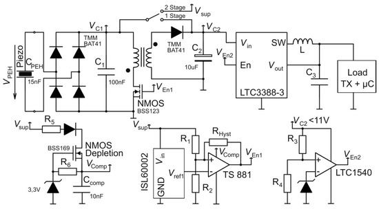
Figure 3.
Schematic of the proposed two-stage circuit for optimal energy extraction of piezoelectric energy harvesters.
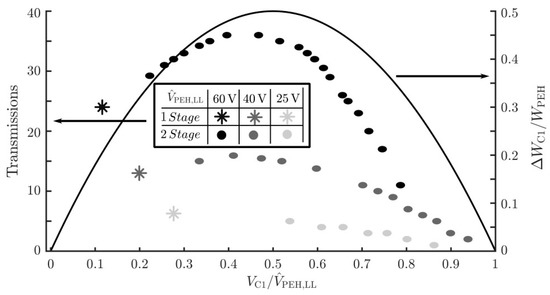
Figure 4.
Evaluation of the energy harvester (Figure 1) and the proposed two-stage energy extraction circuit (Figure 3). The right y-axis data shows the theoretical energy extraction rate. The left y-axis data compares the absolute measured number of sent radio transmissions for the single-stage and the two-stage approach, varying excitation and 𝑉C1/𝑉PEH,LL.
To power electrical applications and be able to maintain high extraction rates at the same time, a second stage is needed, since the required amount of electrical energy has to be provided at defined voltages. The capacity 𝐶2 of the second stage is charged to lower voltage and defined by the needed amount of energy of the application. When the demanded energy level is reached, the second stage will activate the electrical application. Figure 4 shows the evaluation of the proposed circuit and energy harvester for various sinusoidal excitation. It can be seen that the energy extraction efficiency improved about 30% compared to the single-stage approach for high open circuit voltages 𝑉𝑃𝐸𝐻,LL. In the next section, the performance of the system is tested for the desired practical application.
4. Practical Evaluation of the Two-Stage Approach
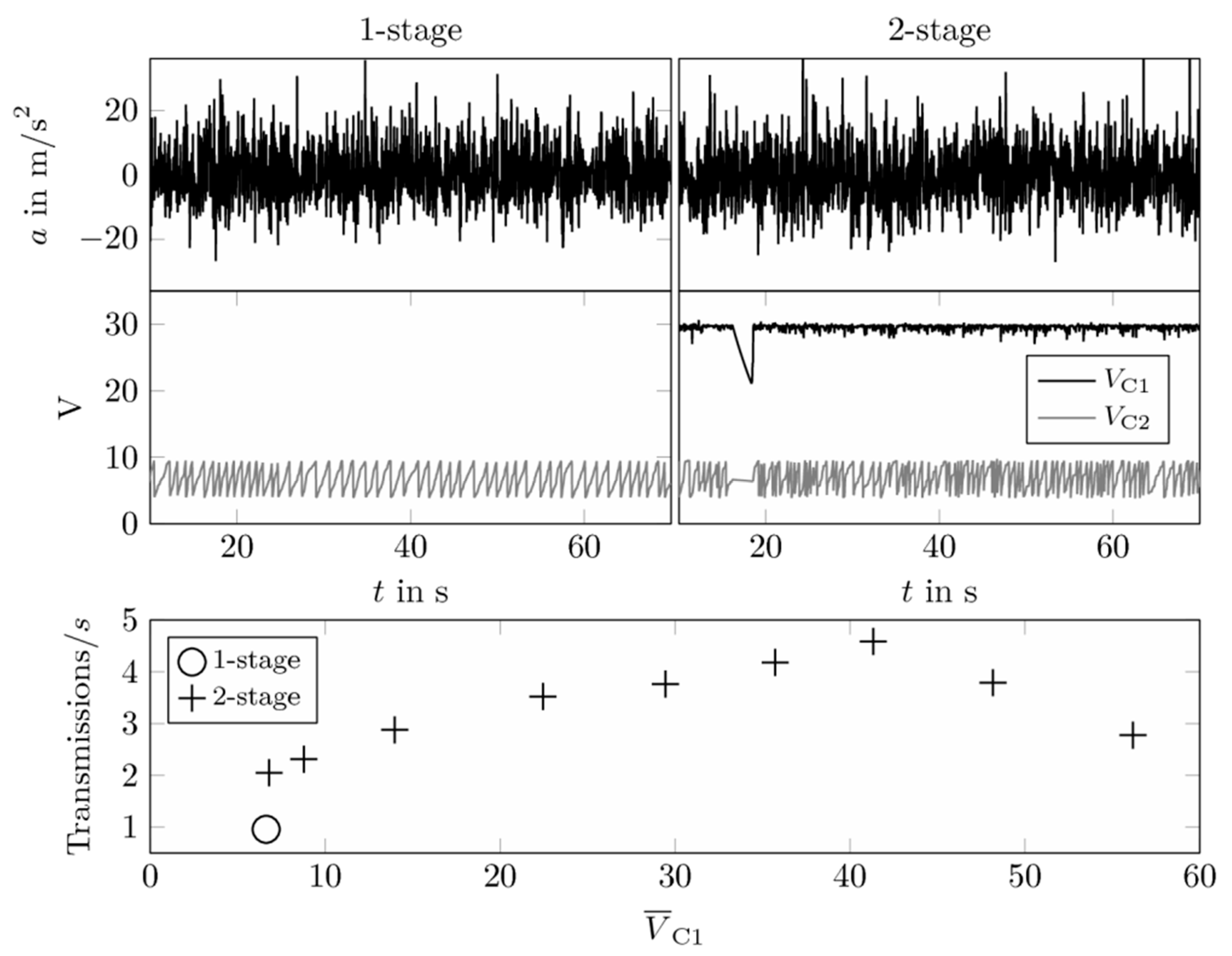
The complete system, as depicted in Figure 1, was tested under realistic conditions by driving the pushcart on an asphalt street for approximately two minutes. Figure 5 compares the performance of the single and two-stage extraction network with respect to their sending rate for the same excitation conditions. As the results show, the two-stage approach achieves a transmission rate, which is more than four times higher than the single-stage approach.
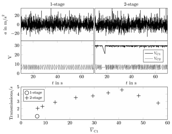
Figure 5.
Practical evaluation and comparison of the single- and two-stage energy extraction networks.
Acknowledgments
This contribution was supported by the Bavarian Ministry of Economic Affairs and Media, energy and Technology as part of the Bavarian Ministry of the Bavarian project “Leistungszentrum Elektroniksysteme (LZE)”.
Conflicts of Interest
The authors declare no conflict of interest. The founding sponsors had no role in the design of the study; in the collection, analyses, or interpretation of data; in the writing of the manuscript, and in the decision to publish the results.
References
- Dorsch, P.; Geyer, S.; Gedeon, D.; Hubert, F.; Rupitsch, S.J. Piezoelektrisches Energy-Harvesting in niederfrequenter Anregungsumgebung mittels kontaktbasierter Frequency-Upconversion. Tm–Technisches Messen 2018, 85, 275–290. [Google Scholar] [CrossRef]
- Rupitsch, S.J.; Ilg, J. Complete characterization of piezoceramic materials by means of wo block-shaped test samples. IEEE Trans. Ultrasonics Ferroelectr. Frequency Control 2015, 62, 1403–1413. [Google Scholar] [CrossRef]
- Lefeuvre, E.; Badel, A.; Richard, C.; Petit, L.; Guyomar, D. A Comparison between several vibration-powered piezoelectric generators for standalone systems. Sens. Actuators A Phys. 2006, 126, 4015–4016. [Google Scholar] [CrossRef]
- Guyomar, D.; Lallart, M. Recent Progress in Piezoelectric Conversion and Energy Harvesting Using Nonlinear Electronic Interfaces and Issues in Small Scale Implementation. Micromachines 2011, 2, 274–294. [Google Scholar] [CrossRef]
- Aguayo, A.E.; Paul, O.; Galchev, T. Integrated synchronous electrical charge extraction system for piezoelectric energy harvesters. In Proceedings of the IEEE International Symposium on Circuits and Systems (ISCAS), Lisbon, Portugal, 24–27 May 2015; pp. 1090–1093. [Google Scholar]


Publisher’s Note: MDPI stays neutral with regard to jurisdictional claims in published maps and institutional affiliations. |
© 2018 by the authors. Licensee MDPI, Basel, Switzerland. This article is an open access article distributed under the terms and conditions of the Creative Commons Attribution (CC BY) license (https://creativecommons.org/licenses/by/4.0/).