Abstract
Honeycomb graphene aerogels offer a combination of graphene wall qualities, such as mechanical strength and binding, and the unique, engineered architecture of honeycombs. The honeycomb structure opens new opportunities for property modification, such as reinforcement with metal nanoparticles, which can increase strength and electrochemical performance. This study uses molecular dynamics simulations to examine the reinforcement of graphene honeycomb aerogels containing 2.7% and 5.8% randomly distributed Ni or Al nanoparticles. Metal nanoparticles considerably increase the resistance to compression: stress increase occurred for aerogels with Al nanoparticles at a density of 1.3 g/cm3, while for aerogels and filled with Ni, stress increase occurred at 2.0 g/cm3. The strengthening mechanism is volume repulsion when Al NPs repel the graphene cell walls, while Ni nanoparticles easily spread along the cell walls and provide less compression resistance, analogous to pure graphene aerogels. The tensile properties remained unaffected by the presence of either nanoparticle type since the same deformation mechanism (cell collapse) occurred for all aerogels. The maximal ultimate tensile strength achieved was 160 GPa. Temperatures ranging from 300 to 3000 K slightly affected the strength of all aerogels.
1. Introduction
Graphene honeycomb aerogels (GHAs) represent a class of ultra-lightweight, highly porous materials with high specific surface area (SSA) and unique mechanical properties [1,2,3,4,5,6]. To date, a large number of graphene aerogel morphologies with considerably different properties have been developed. GHAs are especially promising due to their powerful combination of the intrinsic qualities of graphene (e.g., mechanical strength and binding) and the unique, engineered architecture of the honeycomb structure. Moreover, these properties can be engineered by controlling the architecture, such as cell size and chemical functionalization. The fabrication of such structures is well known, and mass production of GHAs can be achieved cost-effectively using various strategies, including solution-based self-assembly of GO precursors [7], hydrothermal processing [8], freeze casting [9], chemical vapor deposition (CVD) [10], 3D printing [11], and so on [6,12].
Recently, GHAs have been considered to be a hot topic due to their advantages in mass density, deformation ability, mechanical properties, and chemical stability, which allow their application in high-performance pressure sensors [13], energy storage [14], contaminates absorbents/adsorbents [15,16], thermal or acoustic insulators [17], and electromagnetic wave functional materials [18], to name a few [19,20,21,22,23,24]. Despite the many positive characteristics of the cellular morphology of GHAs, there are a number of unresolved problems. For example, precisely controlling the pore size, wall thickness, and uniformity of the honeycomb structure across a large volume is extremely difficult [1]. For GHAs, the other problem is deformability because these structures cannot sustain compression: such structures can support their own weight, but the network can be easily collapsed [25,26,27].
It is well-known that the mechanical behavior of GHAs is highly tunable; factors such as graphene oxide concentration, modification by other atoms, and morphology allow for the precise engineering of properties like stiffness, compressive strength, and anisotropy to meet specific application demands, ranging from energy-absorbing sponges to durable, flexible conductive supports [28]. A promising strategy to improve the properties of GHAs is reinforcement of the empty cells by other nanostructures that will play the role of supporting and volume repulsion. Previously, GHAs reinforced with carbon nanotubes (CNTs) were successfully synthesized and demonstrated improved mechanical and electronic properties [2,29,30,31,32]. In [33], a new, very unusual way to improve the mechanical properties of 3D aerogels was proposed: graphene flakes were wrapped by long CNTs, which prevented the sliding between the graphene flakes and enhanced the stiffness of cell walls. The CNTs may act as a scaffold in the aerogels to resist compressive stress and prevent them from collapse and simultaneously work as a promising adsorbent [34]. In these works, a very interesting morphology was considered: CNTs elongated over the cells of GHAs and attached to them to increase compressibility [33,35]. The CNTs disperse uniformly on the surface and junction points of graphene, which can enhance the stability of the frame structure and pressure resistance [36]. Thus, despite the positive effect of CNTs on different properties of GHA, the morphology, density, concentration, etc., of the resulting structure will affect all these properties [37]. Note that CNTs in such structures are mainly used to improve not the mechanical properties, but to simplify syntheses, improve adhesion, electrical and thermal conductivity of GHAs [33,35,38,39,40].
The addition of CNTs to GHAs, as they can be easily formed during the synthesis process, thus, can be considered as very effective. However, this method has its drawbacks: (i) only CNTs elongated over the surface and junction points of GHAs can serve as the reinforcing element; (ii) the final properties will be affected by a large number of factors—the length and number of layers in CNTs, the final density of the structure, the distribution of CNTs across the structure [33,36], the final morphology combining graphene flakes and nanotubes [33,34], the ratio between their amounts [37]. Moreover, the most common methods for forming porous CNT/graphene hybrid are based on the solution mixing of GO (Graphene Oxide) and CNTs followed by a hydrothermal or lyophilization treatment, which is, however, unfavorable for the uniform and controlled distribution of CNTs in graphene foam [41,42]. Thus, there is a crucial role of structural design for such graphene/CNT composites, which should be taken into account in each case under consideration.
The other impressive way to modify the structure and properties of GAs is the loading of the graphene cells with different nanoparticles. For example, GAs can be very effectively loaded by metal nanoparticles (Pd, Pt, Ni, and Sn) to improve the sensing properties of GAs [43]. Modification with different metal/metal oxides nanoparticles have been previously used to improve the electrochemical performance of GAs to develop their application in batteries and energy storage [44]. Metals such as Co and Ni can adjust the pore textures and surface characteristics and generate the graphitization of created carbon gels [45], or increase hydrogen storage [46]. The choice of a reinforcing element greatly influences both the synthesis process and the future properties of GHAs.
The incorporation of metal nanoparticles (NPs), particularly Ni [46,47,48] or Co [48,49,50,51], has a positive effect on the properties of GHAs. Formation of highly dispersed Re-GO sheets into a gel-like 3D architecture can be achieved in the presence of Ni [52]. The choice of Ni NPs for these purposes is based, firstly, on the significant improvement in the electrochemical properties of the modified aerogel, and also on the fact that Ni is very effective for graphene synthesis [53,54]. It has been found that Ni-doped GHAs demonstrate lower surface area, volume of micropores, and enveloped density but a higher porosity and electrical conductivity [55]. To date, several synthesis methods for incorporating metallic nanoparticles into different carbon lattices have been developed such as polymer thermal treatment, NaCl-assisted strategy, the solvothermal method, and the microwave irradiation method, to name a few [48,49,50,51]. Loading metallic nanoparticles onto a graphene surface requires mixing graphene oxide dispersion with a metal salt solution and needs some additional modifications of methods to obtain structures with the required properties [1,56,57]. To date, the interaction of graphene with various metals has been analyzed, but the use of metal nanoparticles as reinforcing elements for graphene has not been considered.
Inspired by this effect, in the present work, Al and Ni nanoparticles are used as the supporting elements to improve compression resistance. Here, Al and Ni NPs are chosen as examples of two metals that interact very differently with graphene: Ni is known for its strong inter-facial bonding with graphene [58,59], while Al exhibits much weaker interactions [60,61,62]. The type of interaction with the reinforcing element plays a decisive role in changing the properties of the material. The hypothesis is that metal NPs would increase the compression resistance, since Al will repel graphene [63,64], while Ni will spread over the graphene walls (in the same way as CNT elongates over walls and junctions) and also increase strength. The presence of metal NPs will also increase the density of the GHAs, increasing in this way the composite strength. The different natures of the interactions of these metals with graphene will allow us to analyze the best ways to modify the structure and improve the mechanical performance of GHAs.
Despite the fact that the loading of GHAs with CNTs as reinforcing elements demonstrates very positive results in improving both strength and other properties, the loading with metal NPs will affect the properties of GHAs in considerably different ways. Both CNTs and metal NPs (especially Ni) can facilitates the synthesis process [43,45]. While an increase in strength is also expected, for example, due to an increase in the density of the structure [33,37] or due to the repulsion between aluminum and graphene, the change in electrochemical performance, for example, due to the presence of nickel and the thermal and electrical conductivity of the material due to the presence of metal, will also occur [46]. In this work, only the changing of the mechanical properties will be considered, while changes in physical properties will the subject of further research.
Although the tensile and compressive strength can be studied experimentally, the indirect effect cannot be excluded in experimental studies. Molecular dynamic (MD) models have been employed to investigate the tensile/compressive behavior of different graphene nanostructures [64,65,66,67,68]. In [67], deformation mechanisms of GHAs with different morphologies were analyzed. In [69], various mechanical properties and the structural integrity of GHAs as a function of a wide range of simulation parameters were systematically studied. However, the actual description of the mechanical properties is very complicated. Deformation mechanisms have been defined in [70], involving slip-stick sliding, bending, buckling of graphene sheets, collapsing, and densification of graphene cells. Because graphene is prone to bending, and due to the presence of triple junctions in GHAs, load transfer may not be as efficient as in simple graphene structures. MD simulation shows that the mechanical properties of graphene aerogels can be significantly improved by enhancing the structural continuity [71]. Even if the deformation mechanisms for GHAs have been analyzed, the effect of the presence of reinforcing elements cannot be avoided. Furthermore, the direct effect of reinforcements can considerably affect the mechanical properties. Despite the different graphene/metal systems analyzed, the direct effect of reinforcements was not evaluated in these studies for such unusual structures as GHAs.
The hybrid material (graphene honeycomb aerogels filled with metal nanoparticles) is studied under compression and tension via molecular dynamics simulation. The mechanical response of the four different structures containing different distributions of Al or Ni nanoparticles are compared with an empty graphene aerogel. The obtained results proves future prospects for the design of next-generation lightweight structural materials based on graphene honeycomb.
2. Simulation Details
GHAs have a special network structure that is built by stacking graphene sheets compared to other aerogels. The stacking of graphene flakes to the triple junctions allows us to obtain complex structures with different morphology. Figure 1 presents an example of a GHA filled with metal NPs in a perspective view.
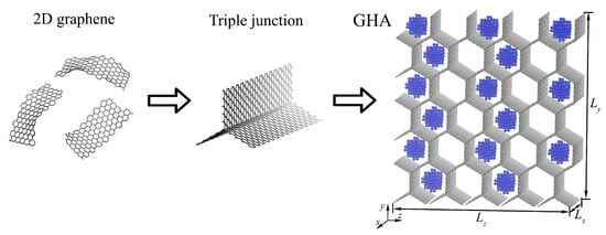
Figure 1.
Two-dimensional graphene flakes combined with graphene triple junction and transformed into three-dimensional GHA (grey color) filled with metal NPs (blue color).
Five different structures are considered, which are GHAs in the form of honeycomb cells: (1) empty GHA; (2) filled with randomly distributed Me NPs, with 2.7% Me, and (3) filled with ordered NPs, with 5.8% Me. Such a small percentage of metal is chosen because a fairly large graphene aerogel is being considered, and it is assumed that the strength can be increased even by a small amount of metal. These values are chosen for two reasons: (i) the diameter of the NPs must be such that they fit into a cell of the GHA without interaction with its walls; (ii) how many cells of the GHA are occupied. Thus, the size of the GHA cells controls the number of atoms in the metal NP, while the number of empty cells controls the total metal content. There are 30 cells that can be filled with NPs: for 5.8% Me, half of the cells are filled, while 2.7% Me means that quarters of the cells are filled. One more characteristic of the structure can be introduced: the ratio of the number of filled cells to the empty ones, which is 0.5 to 0.25.
Five samples are considered: GHA (number of atoms = 26,100), GHA-2.7Ni (number of atoms = 26,100, ), GHA-5.8Ni (number of atoms = 26,100, ), GHA-2.7Al (number of atoms = 26,100, ), and GHA-5.8Al (number of atoms = 26,100, ). Figure 1 presents GHA-5.8Ni, where 15 Ni nanoparticles are orderly settled inside a GHA. For GHAs, two highly symmetric directions—zigzag and armchair—can be distinguished, just as for graphene. In this case, the zigzag direction is along the z-axis, and the armchair direction is along the y-axis.
The diameter of each nanoparticle is 11 Å, and the number of atoms in one NP is 102. NPs are settled in the middle of the honeycomb cell with an average distance between the graphene wall and NP of 5 Å. The size of the simulation cell is Å, Å, and Å.
To obtain any of the studied structures, graphene nanoribbons are combined by the home-made program into graphene honeycomb. At the triple junctions, -hybridization is realized. Figure 1 presents a schematic transformation of 2D graphene to 3D GHA. Commonly, 3D GHAs are synthesized from 2D graphene or graphene oxide in a similar way [1,72,73,74]. Then, the required number of Me NPs with the chosen distribution is added with the same home-made program. Two types of metal NPs are considered—Ni and Al—both initially having a face centered cubic (FCC) lattice; however, during relaxation, FCC ordering is lost due to the small size of the NPs.
MD simulation is based on a mathematical description of the interaction between atoms. The accuracy of predictions made based on the simulation results depends on the accuracy of this description and application to a specific problem. Classical methods of interaction are described using the potential function , which determines the potential energy of a system of N atoms as the function of their coordinates. The dynamics of atoms in the system are governed by Newton’s equation of motion, and the forces acting on each atom are calculated as follows [75]:
where , , and are the force, acceleration, and mass of atom i, and P the potential energy of the system.
For the simulation of such a complex system composed of different atoms, hybrid interatomic potential should be used. For example, to simulate interactions in the graphene/metal system, carbon–carbon (C-C), metal–carbon (Me-C), and metal–metal (Me-Me) interactions should be taken into account. It is possible to describe all interactions (C-C, C-Me, and Me-Me) using just one complex potential, for example, with the modified bond-order potential or reactive force field potential, or different other optimized many-body interatomic potentials. The other way is to reproduce different interactions separately: bond-order potential for C-C, embedded atom method (EAM) for Me-Me, and pair Morse interatomic potential for Me-C. Thus, three potential energy components are required to describe the interactions in the GHA/Me system: , , and . The hybrid potential used for the simulation can be written as follows [64]:
Here, the interaction between metal atoms () is described by the well-known EAM potentials for Ni [76] and Al [77]. The interaction between carbon and metal atoms () is van der Waals and can be described by the simple pair interatomic potential of the Morse type [62,64,78,79]. The parameters , , and for the Morse potential were developed through first-principal calculations and can effectively describe graphene/metal systems. For C-Al interaction, the Morse parameters are = 0.196 eV, = 4.017 1/Å, and = 3.450 Å [62], and for C-Ni interaction, the Morse parameters are = 0.433 eV, = 3.244 1/Å, and = 2.316 Å [78,79].
The interactions between carbon atoms are described using the well-known Adaptive Inter-molecular Reactive Empirical Bond Order (AIREBO) potential [80]:
where is the hydrocarbon REBO potential developed in [81], is a term that adds longer-ranged interactions using a form similar to the standard LJ potential, and describes various dihedral angle preferences in hydrocarbon configurations [80]. It is also very important to consider the modified AIREBO-Morse interatomic potential for the description of C-C interactions during compression. Note that MD simulation is a powerful tool for the analysis of the mechanical properties and fracture behavior of carbon nanostructures, but there are some limitations of the method, and potential functions should be chosen very carefully. Despite the fact that AIREBO can effectively describe the realistic mechanical behavior of graphene, it still faces some challenges while reproducing the C-C bond in hybrid structures.
Note that for the study of metal/graphene systems, there are also exist complex potentials that allow one to simultaneously describe all types of interactions in the system [64,82]. For example, ReaxFF potential was developed for modeling Ni and graphene [82]. Similar complex potentials have been developed for other materials, for example, for Cu or Ti [64]. The use of such potentials makes it possible to take into account the electronic structure of the material; however, within the framework of this work, the application of simple Morse potential in combination with AIREBO for covalent crystals and well-known EAM potentials for metal is enough. The use of a simple paired Morse potential allows one to significantly speed up the calculation while having little effect on the result, as was previously shown for different metals interacting with graphene [64].
All the structures are equilibrated with the NPT ensemble at 0.01 K. The relaxation process is an important element of structure preparation and requires careful analysis [83,84,85]. In the present work, energy minimization of the system occurred by iteratively adjusting atom coordinates. Iterations are terminated when one of the stopping criteria is satisfied: stopping tolerance for energy is 10−24, and stopping tolerance for force is 10−26. Polak–Ribiere version of the conjugate gradient algorithm was used for the calculations.
The initial temperature was equal to 0 K. Relaxation was carried out at 0 K, followed by thermalization at 0 K. Then, relaxation and thermalization of the structure was conducted at 300 K for 10 ps. The structure was relaxed so that the pressure and stress were close to zero.
Then, uniaxial/biaxial tensile/compressive stress at 300 K was applied uni-axially or bi-axially. All the mechanical tests were performed with a quasi-static loading with a strain rate = 0.001 ps−1. For compression, three more temperatures were also considered: 1000, 2000, and 3000 K. In this case, only compression along y-axis (uniaxial) and in the -plane (biaxial) was considered. Compression along the x-axis was not investigated because the chosen periodic boundary conditions along the x-axis compression along this direction are not of interest for the present work. Tensile strain was applied along the y-axis and also in the -plane. Compression was conducted until the density of diamond (3.5 g/cm3) was reached, so the simulation time depended on the structure under consideration; tension was carried out until fracture and also depended on the type of structure.
To calculate the von Mises stress during tension and compression, the following is used:
where , , , , , are the stress components calculated during the simulation.
All the simulations were conducted using MD simulations in the LAMMPS simulation package [86,87,88,89,90]. The equations of motion for the atoms were integrated using the fourth-order Verlet method [91] with a time step of 0.2 fs. Periodic boundary conditions were applied along the x-, y-, and z-axes. A Nose–Hoover thermostat was used to control the system temperature when simulating the relaxation and tension. For visualization of the structure, the molecular graphics programs VMD (Visual Molecular Dynamics) and OVITO were used [92,93].
3. Simulation Results
3.1. Structure Relaxation
Figure 2 presents Al and Ni nanoparticles before and after relaxation (a) and GHA with 2.7% nanoparticles after relaxation at 300 K (b) and after the first steps of the MD simulation (c). As can be seen, after relaxation, the NPs remain in the crystal structure. In the initial state, both nanoparticles have FCC lattice, but after relaxation, especially at 300 K, a slight displacement of the atoms near the equilibrium position is observed, which is more pronounced for Ni. The NPs remain stable during relaxation and further simulation.
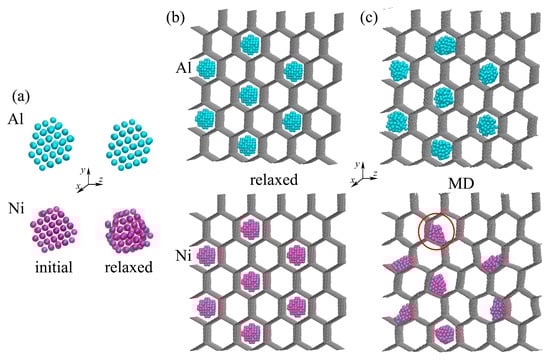
Figure 2.
(a) Snapshots of the NPs before and after relaxation. (b,c) Snapshots of the GHA with Al and Ni nanoparticles after relaxation (b) and after the first steps of the MD simulation (c). Al NPs are shown in blue, and Ni NPs are shown in purple.
For GHAs with Ni and Al NPs after relaxation, the structure is stable too; the NPs have a spherical shape. However, even the very first steps of the MD simulation lead to a significant change in the structure; aluminum nanoparticles lose their crystal structure due to strong repulsion from the walls of the GHA, and the Ni nanoparticles attach to the walls of the cells of the GHA (shown in the red circle) due to the strong interaction between graphene and Ni.
3.2. Compression
Figure 3 present the stress–strain and stress–density curves during uniaxial compression. Stress is zero when g/cm3, which is due to the cell collapse during the first deformation stages. Thus, both the density and strain are shown not from zero. GHAs are famously known for being some of the lightest solid materials with a remarkably low density. This incredibly low density is a direct result of its structure, which is mostly empty space. GHAs have a porosity often exceeding 99.9%. This means less than 0.1% of the volume is solid graphene, and the rest is air-filled pores. Again, this is the reason why these structures are highly compressive. At the very beginning of compression, the applied stress is low. The interconnected network of the GHA elastically bends and buckles. The walls of graphene cells can oscillate slightly at this deformation stage, and the pores (empty space) begin to collapse slightly.
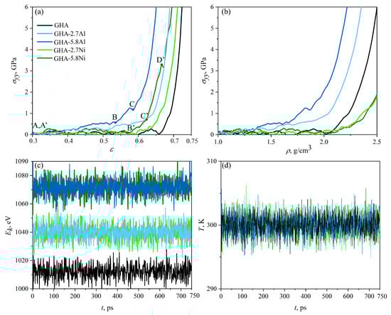
Figure 3.
Stress–strain (a) and stress–density (b) curves during uniaxial compression along the y-axis. Key points are marked as A-C, A’-D’ (c,d) Kinetic energy, , and temperature T as a function of simulation time during uniaxial compression.
Figure 3c,d presents the kinetic energy of the system, , and temperature T as the function of the simulation time during uniaxial compression for all the structures under consideration. As can be seen, during compression, there are no unexpected jumps in the kinetic energy. Temperature oscillates near the chosen value of 300 K, controlled by the Nose–Hoover thermostat. As can be seen, the empty GHA has the lowest kinetic energy, GHAs with 2.7% metal atoms have slightly increased kinetic energy, and an increase in the metal volume to 5.8% again slightly increases the system’s energy. The same was found for the potential and total energy of the systems.
As can be seen, the greatest resistance to compression is demonstrated by GHA-5.8Al: even at = 0.35, a gradual stress increase begins. The key points A (A’), B (B’), and C (C’), where important structural changes occur, are presented for two stress–strain (density) curves for GHA-5.8Al, dark-blue line (GHA-5.8Ni, dark-green line). For GHA-5.8Al, up to point B, the stress increase is smooth, after which a sharp increase in stress is observed, which is associated with structural rearrangements. Structural changes will be discussed further. After point C, the stage of pre-critical irreversible deformation occurs, when there is no longer a possibility for further compression. Here, all the considered structures can be compressed to the density up to that of diamond (3.6 g/cm3); however, at such high densities and applied compression strain, amorphisation of the graphene network occurred, which is not in the area of interest for the present work. Thus, the pre-critical regime is also not specifically analyzed, because structural transformations and phase transitions cannot be properly reproduced with the applied potential functions.
A very similar situation can be seen for GHA-2.7Al: stress increase begins at = 0.35, and slow stress increase occurred up to = 0.64, which is followed by the pre-critical regime. The density of the structure increases in a similar way for GHA-5.8Al and GHA-2.7Al until g/cm3, after which the inserted amount of Al nanoparticles becomes critical and fast stress increase occurs for GHA-5.8Al even at lower density.
For GHA filled with Ni NPs (GHA-5.8Ni), deformation behavior is considerably different: stress fluctuates near zero until = 0.56 (point B’), after which a slight increase in stress is observed up to point C’, which is followed by the pre-critical stage of deformation with the sharp stress increase. The lower content of Ni NPs results in a slower increase of stress up to = 0.64, and the pre-critical stage starts at = 0.67. As can be seen, empty GHA (black solid line) can be easily compressed: stress fluctuates near zero until = 0.61.
From the stress–density curves (see Figure 3b), it is clear that the critical stress and critical density correspond to 1.83 g/cm3 for GHA-5.8Al; 2.25 g/cm3 for GHA-2.7Al, while for both structures with nickel and the empty GHA, the critical density is 2.25 g/cm3. We can conclude that the presence of nickel NPs almost does not affect the process of deformation in comparison with the empty GHA. This happens as a result of the strong interaction between graphene and Ni and the good distribution of Ni NPs in graphene cells. Moreover, the density of GHA-2.7Ni and GHA-5.8Ni during compression changes in the same manner. Note that Ni nanoparticles can even simplify the process of cell collapse: Ni NPs ancored on one side of the graphene honeycomb cell attract the other side due to the strong interaction with graphene.
Figure 4 presents snapshots of the structure during uniaxial compression along the y-axis for GHA-5.8Al (a) and GHA-5.8Ni (b) in the key points from the stress(density)–strain curves. The structure of empty GHA during deformation can be found in numerous works [27,67,69]. Compression of the empty GHA occurs via the gradual collapse of all cells, which happens quite easily, resulting in the stress in the structure remaining zero up to high strain and high densities of the structure.
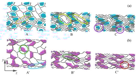
Figure 4.
Snapshots of the structure during uniaxial compression along the y-axis for GHA-5.8Al (a) and GHA-5.8Ni (b). Corresponding key points A-C and A’-C’ are shown in Figure 3. Al NPs are shown in blue color, and Ni NPs are shown in purple.
The presence of NPs in the GHA cells slows down its deformation and the collapse of the graphene cells. For GHA-5.8Ni at = 0.3, some cells have already collapsed (example is shown in the orange ellipse); however, the structure still has enough resources for further deformation without stress increase. At point B, almost all open cells without NPs are collapsed. Examples of the last opened cells are shown in yellow circles. Note that the cells filled with aluminum NPs are considerably stressed due to the mutual interaction between graphene and Al. At point C, the last resource for deformation is exhausted, and a strong stress increase begins. As can be seen from the figure, even at low strain, aluminum NPs strongly resist deformation of the material since they literally push off the walls of the GHA. There is always a free space between NPs and graphene walls (examples are shown in purple circles). This is common for Al/graphene systems: they have very low interaction energy and tend to move from each other [60,61,62].
A completely different situation is observed for the structure with nickel (GHA-5.8Ni) at = 0.3: a much larger number of cells are open, while nickel NPs are stuck to the walls (example is shown in light-green circle) of the GHA since Ni interacts well with graphene [58,59]. As can be seen, at point A’, there are much fewer collapsed cells (example is shown in the light-blue circle), which is explained by the fact that in the structure with Al, an aluminum NP, repels the wall of the honeycomb, forcing it to interact more strongly with the neighboring graphene wall. This leads to a faster collapse of open cells during deformation. At point B’, all cells gradually collapse, but the increase in stress is slow since Ni NPs easily spread along the walls of the GHA cells (example is shown in the dark-green circle). The small NPs become very plastic and line up well in cells of various shapes, even adapting to this shape. At point C’, the deformation resource is also exhausted: the presence of Ni NPs leads to a faster collapse of cells and a rapid accumulation of stress compared to in an empty GHA. As can be seen from Figure 4b, at point C’, not all the cells are fully collapsed (the example is shown in the red circle). At point D’ Figure 3a, there is a small stress drop which corresponds to the moment when all the cells become planar, without any free volume.
Figure 5 presents the stress–strain and stress–density curves during biaxial compression. Stress during biaxial compression is calculated as . In this case, stress increase begins earlier, and the stress–strain curve is presented from zero strain, which, however, corresponds to a density of 1.0 g/cm3. Figure 6 presents snapshots of the structure during uniaxial compression for GHA-5.8Al (a) and GHA-5.8Ni (b) in the key points from the stress(density)–strain curves.
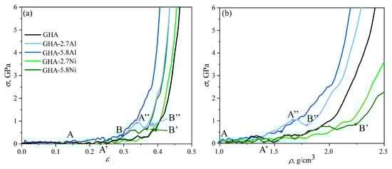
Figure 5.
Stress–strain (a) and stress–density (b) curves during biaxial compression along the y- and z-axis. Letters A, B, A″, B″ marked important deformation stages.
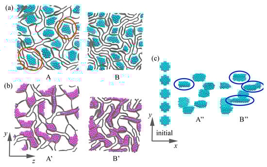
Figure 6.
Snapshots of the structure during biaxial compression for GHA-5.8Al (a) and GHA-5.8Ni (b). (c) Snapshots of the Al NPs in GHA-2.7Al during biaxial compression. Corresponding key points A, B, A″, B″ are shown in Figure 5. Al NPs are shown in blue, and Ni NPs are shown in purple.
In the case of biaxial compression, deformation occurs much faster, with critical compression strains of 0.34 for GHA-5.8Al and GHA-2.7Al, 0.36 for GHA-5.8Ni, and 0.4 for GHA-2.7Ni. However, the deformation behavior is similar to that under uniaxial compression: Al NPs repel the cell walls, preventing the collapse of the cells of GHA; Ni NPs particles spread over the cell walls. Pre-critical stresses are reached earlier, as well as critical densities of the structure, which can be seen both on the stress (density)–strain curves (see Figure 5) and from the snapshots of the structure (see Figure 6).
Interestingly, in the stress–strain curve for GHA-2.7Al, there is a stress drop at = 0.34, which is associated with the rearrangement of NPs inside the cells. As was mentioned above, Al NPs resist deformation and repel graphene walls. Again, there is always an empty space between NPs and cell walls; examples are shown in the red circles in Figure 6a. In the case of uniaxial deformation, Al NPs have the ability to change their shape in the direction normal to the compression direction, while during biaxial compression, there is no such possibility, and Al NPs begin to change their shape along the x-axis (for reference, see Figure 1). As can be seen from Figure 6c, initially, all NPs are located in the same position along the x-axis; however, during compression, they begin to shift slightly relative to each other to allow the neighboring graphene cells easily collapse. At = 0.34, Al NPs not only change their position along the x-axis but also change their shape and become elongated along the x-axis (point B″ in Figure 6c) (examples are shown in blue circles). This corresponds to a small compensation for the stressed state, which is followed by the pre-critical regime.
When compressed, the honeycomb cells do not fracture immediately. Instead, the flexible graphene walls undergo elastic bending and buckling. The interconnected network distributes the stress throughout the entire structure. Metal NPs are more effective reinforcing elements than CNTs because nanotubes tend to collapse or stack in bundles [94,95], which could not prevent the GHA from collapse. The deformation mechanisms in compression are graphene branch bending and branch wall elastic depression, which do not utilize the exceptionally high in-plane mechanical properties of graphene [96]. Monolayer graphene walls are flexible and can be easily crumpled, thus strengthening the interaction between different graphene sheets [97].
Figure 7a presents stress under compression as a function of density for three representative structures and four temperatures of 300, 1000, 2000, and 3000 K together with snapshots of the structure. Compressive strength decreases slightly with increasing temperature, so at 300 K, a strong increase in stress begins with a density of 2.0 g/cm3, while at 3000 K, this begins at a lower density of 1.8 g/cm3 for GHA with Al. Similar results were obtained for pure aerogels and aerogels with Ni. Thus, temperature facilitates the compression process. This is explained by the fact that the deformation is determined by the deformation of the graphene aerogel: at higher temperatures, the bending of the cell walls occurs easily; the presence of increased numbers of folds increases the rigidity of the structure. The presence of metal particles does not affect the deformation process; Ni particles melt at 1200 K, as was shown in [98,99,100], and at 2000 and 3000 K, they are completely melted and spread over the cell walls in a thin layer; they cannot provide any strengthening. The shift in the critical stress accumulation density is explained by the presence of denser elements in the aerogel structure; aluminum particles that are repelled by the graphene walls provide a faster stress increase. At 1000 K, the deformation process is very close to that at 300 K.
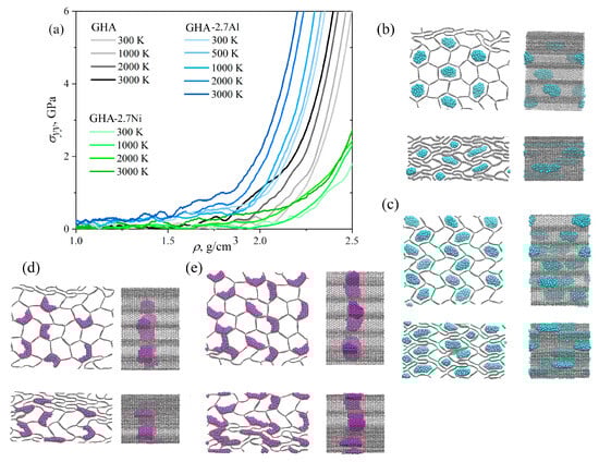
Figure 7.
(a) Stress–density curves during compression at 300, 1000, 2000, and 3000 K for all the structures under consideration. Snapshots of the structure at 1000 K in two projections: (b) GHA with 2.7% Al, (c) GHA with 5.8% Al, (d) GHA with 2.7% Ni, (e) GHA with 5.8% Ni. The density, in g/cm3: (b) = 1.5, 2.2; (c) = 1.5, 2.0; (d) = 1.5, 2.35; (e) = 1.5, 2.22. GHA is shown by grey color, Al NPs are shown by blue color, Ni NPs are shown by purple color.
Despite stress–strain curves under compression at high temperatures being presented only for 2.7% Me atoms, all the calculations were conducted for both structures. However, the deformation behavior of GHA with 5.8% Me under compression can be described based on the presented results. As for 2.7%, temperature increases the compression resistance due to the faster crumpling of the graphene walls. As can be seen from Figure 3, higher stress is achieved at a lower density for GHA with 5.8% Me in both cases. At higher temperatures, a similar trend is observed: curves shift to lower density, but qualitatively, the same behavior occurs.
During deformation, Al, for example, at 500–1000 K starts to melt even at low strain. Similarly, at higher temperatures, the particles melt almost immediately, with NPs losing their spherical shape and elongating along the axis and the cells. As can be seen, the Al still repels the walls, which results in stress increase. But, stress increase is not the result of the temperature increase, but just due to the special interaction between Al and graphene. During the deformation process, the Al particles move freely along the aerogel axis, or along the entire length of the cell: the soft, melted Al NPs can move freely (see the snapshots). The same can be seen for 5.8% Al: melted NPs elongate along the honeycomb axis, right in the same way. This explains why there is almost no difference in the deformation of GHA with two different numbers of Al NPs. Stress–density curves are not presented for 5.8% Al because the one difference is the increase in density.
A different situation is observed for GHAs with Ni. Firstly, Ni NPs are attached at one place and do not move anywhere during the deformation process. Secondly, the number of nanoparticles has no effect on the deformation process; they are easily spread along the cell walls, especially at high temperatures. This is very similar to the behavior for graphene, which completely covers Ni nanoparticles [64,100]. The strengthening is explained precisely by the formation of a large number of folds in the GHA, and only a small degree of density increase took place due to the presence of NPs. Similarly, the curves for 5.8% Ni are not drawn. But, from the snapshots of the structure, it is clear that the only difference is a slightly higher density of the material due to the presence of metal.
One of the important findings is the critical temperature, which corresponds to the melting temperature of the NPs. As was shown previously, the melting temperature of Al NPs is 424–448 K [64,101], while for Ni NPs, it is 1200–1400 K [64,98,99]. Thus, to clarify this, we considered one more temperature for GHAs with Al: at 500 K. We showed that before the melting temperature of the NPs, modification improves the compressive strength, while at higher temperatures, the NPs have almost no effect on the process. At temperatures lower than melting, Me particles cannot deform so easily.
It can be concluded that at temperatures higher than 1200 K (500 K), the effect of Ni (Al) NPs is not pronounced, while modification of the structure by NPs perfectly works for lower temperatures. At high temperatures, the increase in the compression resistance is explained by structural transformation of the GHA itself.
The compression behavior of GHAs is dictated by their nanoscale architecture, even when modification is not considered [1,67,102]. Numerous experiments have proven that the mechanical properties of GAs are significantly influenced by the intrinsic properties of graphene sheets, the microstructural parameters, and the structural design [1]. A structure with thicker, more continuous graphene sheets and a higher degree of cross-linking exhibits elastic, reversible deformation, recovering its original shape. In contrast, a fragile network of thin, sparsely connected strands undergoes irreversible, brittle collapse and plastic deformation under the same load. As in [103,104], junctions of GHAs play a very important role in the compressive behavior, even in the presence of metal NPs. As can be seen, GHA plays an important, even leading role in the deformation behavior. Very similar structural changes have been observed experimentally [19] and in simulations [105].
3.3. Tensile Behavior
Figure 8a presents the stress–strain (density) curves during tension of the GHA along the y-axis (solid lines). As can be seen, neither the presence of Al NPs nor Ni NPs has any effect on the tensile deformation. The tension of the empty GHA has been analyzed earlier in [27,67,69], where it was shown that strength under tension is anisotropic, and in different directions, GHA is deformed in different ways. In addition, pure GHA honeycomb turns into cellular GHA under tension along the zigzag direction. The main deformation mechanism is also the collapse of the cells as well as under compression.
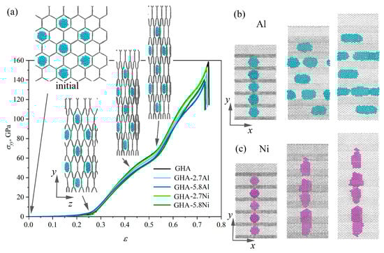
Figure 8.
(a) Stress–strain curves during uniaxial tension with snapshots of structure GHA-2.7Al in a projection to the plane at critical points. (b,c) Snapshots of the structure in a projection to the plane for (b) GHA-2.7Al and (c) GHA-2.7Ni. Al NPs are shown in blue, and Ni NPs are shown in purple.
Figure 8b presents a snapshots of the structure during tension: an example is shown for GHA-2.7Al; however, for structures with nickel and a large number of Al NPs, the deformation behavior is absolutely similar. Figure 8a shows the stress–strain curves and snapshots of the GHA-2.7Al in a projection to the plane. Figure 8b shows snapshots of the GHA-2.7Ni in a projection to the plane, for comparison. As can be seen, from the curves and snapshots, up to = 0.28, the honeycomb cells collapse easily without any stress increase. At = 0.28, all the cells are already collapsed, and there are no differences with an empty GHA. Ni NPs easily occupy the entire area of the cells in the collapsed state, transforming into flattened NPs. In the case of Al NPs, which should resist compression, rigid graphene walls compress the Al NPs and force them to spread along the x-axis (as in case of biaxial compression). The Al NPs behave in this way in order to reduce the area of contact with the graphene walls. At = 0.52, pre-critical state is achieved, then tension occurs due to the elongation of the covalent bonds in the basal plane of the graphene walls. Generally speaking, this process begins at about = 0.42. After = 0.52, the bonds inside the graphene walls are highly stressed, which results in the fast stress increase.
In [67], a maximum ultimate strength of 160 GPa in tension in the y direction for the same GHA was observed. It was also found that deformation behavior was considerably dependent on the morphology. Highly anisotropic behavior in tension along the different axes was also discussed. Moreover, it was shown that high stress concentration can be found near triple junctions, and the most strained bonds in graphene walls are oriented along the tensile direction. Very similar mechanical behavior of graphene networks under tension was shown in [96,97,106,107]. High strength and modulus can be achieved for monolayer graphene networks both under uniaxial tensile and compressive loading, which is attributed to the combination of out-of-plane deformation of monolayer graphene and inter-graphene slippage [97]. The mechanical performances under tension are principally related to their topology [106].
Figure 9a presents the stress and the length of the cell wall as a function of strain during biaxial tension together with snapshots of the structure. Changes in the representative valence angles and and covalent bonds a, b, c are also presented as a function of strain. During uniaxial and biaxial tension, deformations occurred in a similar way; however, under uniaxial tension, the structure realized the possibility of hexagon collapse, which results in zero stresses for high strain (up to ). For biaxial tension, four deformation stages are observed: elastic strain (yellow region); deformation hardening (green and blue region); and pre-critical strain (purple region). Here, the main deformation mechanisms are the elongation of bonds and changes in the valence angles. These changes are presented in Figure 9b,c: change in the cell wall length; change in bonds a and b, change in valence angles and .
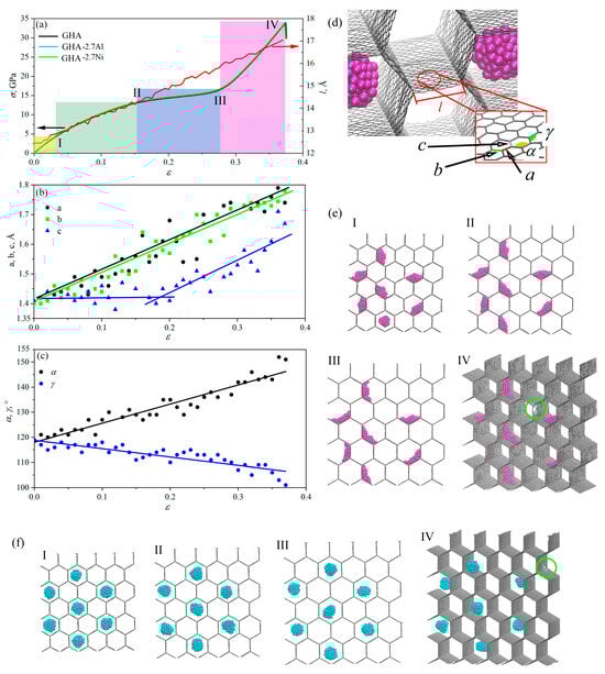
Figure 9.
(a) Stress–strain curves and changes in the length of the cell wall during biaxial tension for GHA, GHA-2.7Al, and GHA-2.7Ni. (b–d) Valence angles and covalent bonds in the structure. All parameters are shown in (c). (e,f) Snapshots of the structure during biaxial tension for GHA-2.7Ni and GHA-2.7Al (f). Critical points I–IV are shown on the stress–strain curve. GHA is shown by grey color, Al NPs are shown by blue color, Ni NPs are shown by purple color.
Under hydrostatic tension, Ni particles also anchored to the honeycomb walls, while Al nanoparticles stayed in the center of the cell, repelled by the walls. It is clearly seen that with increasing deformation, Al NPs remained almost unchanged staying at the maximum distance from the cell walls (see Figure 9e,f). The length of the cell wall increased almost uniformly with deformation (see Figure 9a, red curve).
Deformation occurred through elongation of the bonds and changes in the valence angles in the basal graphene plane. Bonds a and b continuously elongated, while bond c started to elongate at point II, which allowed further stress increase, but very slow, until point III. Then, a sharp stress increase began. The increase in the length of the cell wall l occured both due to the elongation of covalent bonds within the wall and due to a change in the valence angles (increase in the angle and a corresponding decrease in the angle. The moment of fracture is shown by a green circle and occurred near the triple junction.
In this case, it turned out that doubling the percentage of metal atoms (from 2.7 to 5.8%) did not lead to significant differences in the strength or tensile behavior. The deformation mechanism is absolutely the same for two metal contents. Al NPs are held in the center of the cells, Ni NPs are spread as thin metal layers along the walls of graphene cells. Since the overall percentage of metal atoms is really very small, they do not affect the tensile process. The main conclusion here is that the biaxial tension is determined only by the deformation of the pure GHA. Ni NPs for both metal contents spread along the walls and can only slightly change the deformation process. However, even the fracture occurs in a region free of metal. For Ni, this is explained by the fact that Ni is not only attracted to graphene itself but also holds the carbon atoms together, so the fracture itself cannot occur here. For Al, this is explained by the fact that the particles move in the center of the cell, repelling from it as they moves towards graphene. They also cannot affect the tensile behavior of GHA under biaxial tension.
The effect of temperature on the fracture behavior of GHA was studied previously in [27]: temperature slightly affects strength and failure strain for GHA.
4. Conclusions
In this work, the mechanical properties of a graphene honeycomb aerogel modified with Ni and Al nanoparticles were investigated in detail using molecular dynamics simulations. This study compared the response of pure graphene aerogel with structures containing different distributions and concentrations (2.7% and 5.8%) of Ni and Al nanoparticles under uniaxial and biaxial compression, as well as tension.
The incorporation of metal nanoparticles substantially improves the compressive resistance of graphene aerogels. The reinforcement effect is most pronounced for structures filled with aluminum nanoparticles. The Al nanoparticles act as supporting elements that physically repel the graphene cell walls, resisting collapse and leading to an earlier stress increase during compression. The strong chemical interaction between Ni and graphene walls results in perfect distribution of Ni nanoparticles inside graphene cells. The presence of Ni nanoparticles also provides some resistance but allows the structure to deform more easily.
Biaxial compression leads to earlier stress accumulation and lower critical strains compared to uniaxial compression. Under biaxial loading, Al NPs have less freedom to deform and rearrange, leading to earlier structural rearrangements and stress drops on the stress–strain curve. Ni NPs continue to spread along cell walls under both loading conditions, offering minimal resistance.
Temperature increase from 300 K to 3000 K slightly reduces compressive strength for all structures due to the thermal fluctuations. At 1000 K, the deformation process is very close to that at 300 K. At higher temperatures, graphene walls bend more easily, and Ni NPs melt and spread as thin layers, decreasing their reinforcing capability. At critical stress, the density shifted to lower values with increasing temperature, especially for Al-reinforced GHA. At temperatures higher than 1200 K, the effect of NPs became not pronounced, while modification of the structure by NPs perfectly worked for lower temperatures. At high temperatures, the increase in the compression resistance is explained by structural transformation of the GHA itself.
The deformation mechanism under tension is the collapse of the cells and shown to be unaffected by the presence of either type of metal nanoparticle. The honeycomb structure under tension transforms to a cellular structure. Ni nanoparticles are anchored on the walls of the graphene cells, while Al nanoparticles spread over the graphene aerogel.
In summary, this study demonstrates that embedding weakly interacting metal nanoparticles, such as aluminum, is a highly effective strategy for enhancing the compressive strength of graphene aerogels without compromising their ultra-low weight. The atomistic insights into the deformation mechanisms offer a valuable guideline for the computational design and experimental synthesis of next-generation lightweight, high-performance graphene–metal composite materials. This work demonstrates improvement in compression resistance; however, the the loading of GHA with metal NPs, especially such a different one, will greatly affect the physical properties of the GHA, for example, when it is used in sensors or for energy storage, which remains to be investigated. Another direction for the development of this work could be the study of composites based on Al and graphene, which are quite difficult to fabricate.
Author Contributions
Conceptualization, J.B. and P.Z.; Methodology, E.R.; Formal Analysis, J.B. and P.Z.; Investigation, E.R.; Writing—Original Draft Preparation, E.R. and P.Z.; Writing—Review and Editing, J.B. All authors have read and agreed to the published version of the manuscript.
Funding
The work of P.Z. was supported by the Grant of the Russian Science Foundation (24-22-20038) and the Grant of the St. Petersburg Science Foundation (24-22-20038). The work of E.R and J.B. was supported by the State Assignment of IMSP RAS.
Institutional Review Board Statement
Not applicable.
Informed Consent Statement
Not applicable.
Data Availability Statement
The data presented in this study are available upon request from the corresponding author due to privacy restrictions.
Conflicts of Interest
The authors declare no conflicts of interest.
Abbreviations
The following abbreviations are used in this manuscript:
| MD | Molecular dynamics |
| GHA | Graphene honeycomb aerogel |
| NP | Nanoparticle |
References
- Trembecka-Wójciga, K.; Sobczak, J.J.; Sobczak, N. A comprehensive review of graphene-based aerogels for biomedical applications. The impact of synthesis parameters onto material microstructure and porosity. Arch. Civ. Mech. Eng. 2023, 23, 133. [Google Scholar] [CrossRef]
- Afroze, J.D.; Tong, L.; Abden, M.J.; Yuan, Z.; Chen, Y. Hierarchical honeycomb graphene aerogels reinforced by carbon nanotubes with multifunctional mechanical and electrical properties. Carbon 2021, 175, 312–321. [Google Scholar] [CrossRef]
- Zhang, B.; Zhang, J.; Sang, X.; Liu, C.; Luo, T.; Peng, L.; Han, B.; Tan, X.; Ma, X.; Wang, D.; et al. Cellular graphene aerogel combines ultralow weight and high mechanical strength: A highly efficient reactor for catalytic hydrogenation. Sci. Rep. 2016, 6, 25830. [Google Scholar] [CrossRef]
- Nardecchia, S.; Carriazo, D.; Ferrer, M.L.; Gutiérrez, M.C.; del Monte, F. Three dimensional macroporous architectures and aerogels built of carbon nanotubes and/or graphene: Synthesis and applications. Chem. Soc. Rev. 2013, 42, 794–830. [Google Scholar] [CrossRef] [PubMed]
- Zhang, Q.; Xu, X.; Li, H.; Xiong, G.; Hu, H.; Fisher, T.S. Mechanically robust honeycomb graphene aerogel multifunctional polymer composites. Carbon 2015, 93, 659–670. [Google Scholar] [CrossRef]
- Xia, Y.; Gao, C.; Gao, W. A review on elastic graphene aerogels: Design, preparation, and applications. J. Polym. Sci. 2022, 60, 2239–2261. [Google Scholar] [CrossRef]
- Qian, Y.; Ismail, I.M.; Stein, A. Ultralight, high-surface-area, multifunctional graphene-based aerogels from self-assembly of graphene oxide and resol. Carbon 2014, 68, 221–231. [Google Scholar] [CrossRef]
- Bao, Q.; Hui, K.; Hui, K.; Wang, Y.; Hong, X. Hydrothermal self-assembly and supercapacitive behaviors of Co(II) ion-modified graphene aerogels in H2SO4 electrolyte. Mater. Res. Bull. 2014, 56, 92–97. [Google Scholar] [CrossRef]
- Wang, C.; Chen, X.; Wang, B.; Huang, M.; Wang, B.; Jiang, Y.; Ruoff, R.S. Freeze-Casting Produces a Graphene Oxide Aerogel with a Radial and Centrosymmetric Structure. ACS Nano 2018, 12, 5816–5825. [Google Scholar] [CrossRef]
- Song, Y.; Li, B.; Yang, S.; Ding, G.; Zhang, C.; Xie, X. Ultralight boron nitride aerogels via template-assisted chemical vapor deposition. Sci. Rep. 2015, 5, 10337. [Google Scholar] [CrossRef] [PubMed]
- Yao, B.; Chandrasekaran, S.; Zhang, H.; Ma, A.; Kang, J.; Zhang, L.; Lu, X.; Qian, F.; Zhu, C.; Duoss, E.B.; et al. 3D-Printed Structure Boosts the Kinetics and Intrinsic Capacitance of Pseudocapacitive Graphene Aerogels. Adv. Mater. 2020, 32, 1906652. [Google Scholar] [CrossRef]
- Shao, J.; Lv, W.; Yang, Q. Self-Assembly of Graphene Oxide at Interfaces. Adv. Mater. 2014, 26, 5586–5612. [Google Scholar] [CrossRef]
- Cao, X.; Zhang, J.; Chen, S.; Varley, R.J.; Pan, K. 1D/2D Nanomaterials Synergistic, Compressible, and Response Rapidly 3D Graphene Aerogel for Piezoresistive Sensor. Adv. Funct. Mater. 2020, 30, 2003618. [Google Scholar] [CrossRef]
- Hong, J.; Bak, B.M.; Wie, J.J.; Kong, J.; Park, H.S. Reversibly Compressible, Highly Elastic, and Durable Graphene Aerogels for Energy Storage Devices under Limiting Conditions. Adv. Funct. Mater. 2014, 25, 1053–1062. [Google Scholar] [CrossRef]
- Li, C.; Yang, J.; Pachfule, P.; Li, S.; Ye, M.Y.; Schmidt, J.; Thomas, A. Ultralight covalent organic framework/graphene aerogels with hierarchical porosity. Nat. Commun. 2020, 11, 4712. [Google Scholar] [CrossRef]
- Luo, Y.; Jiang, S.; Xiao, Q.; Chen, C.; Li, B. Highly reusable and superhydrophobic spongy graphene aerogels for efficient oil/water separation. Sci. Rep. 2017, 7, 7162. [Google Scholar] [CrossRef]
- Rapisarda, M.; Malfense Fierro, G.P.; Meo, M. Ultralight graphene oxide/polyvinyl alcohol aerogel for broadband and tuneable acoustic properties. Sci. Rep. 2021, 11, 10572. [Google Scholar] [CrossRef]
- Huang, X.; Yu, G.; Zhang, Y.; Zhang, M.; Shao, G. Design of cellular structure of graphene aerogels for electromagnetic wave absorption. Chem. Eng. J. 2021, 426, 131894. [Google Scholar] [CrossRef]
- Qiu, L.; Liu, J.Z.; Chang, S.L.; Wu, Y.; Li, D. Biomimetic superelastic graphene-based cellular monoliths. Nat. Commun. 2012, 3, 1241. [Google Scholar] [CrossRef]
- Qiu, L.; Huang, B.; He, Z.; Wang, Y.; Tian, Z.; Liu, J.Z.; Wang, K.; Song, J.; Gengenbach, T.R.; Li, D. Extremely Low Density and Super-Compressible Graphene Cellular Materials. Adv. Mater. 2017, 29, 1701553. [Google Scholar] [CrossRef]
- Guan, X.; Wang, Z.; Zhao, W.; Huang, H.; Wang, S.; Zhang, Q.; Zhong, D.; Lin, W.; Ding, N.; Peng, Z. Flexible Piezoresistive Sensors with Wide-Range Pressure Measurements Based on a Graded Nest-like Architecture. ACS Appl. Mater. Interfaces 2020, 12, 26137–26144. [Google Scholar] [CrossRef]
- Yao, W.; Mao, R.; Gao, W.; Chen, W.; Xu, Z.; Gao, C. Piezoresistive effect of superelastic graphene aerogel spheres. Carbon 2020, 158, 418–425. [Google Scholar] [CrossRef]
- Li, Q.; Liu, Y.; Chen, D.; Miao, J.; Lin, S.; Cui, D. Highly Sensitive and Flexible Piezoresistive Pressure Sensors Based on 3D Reduced Graphene Oxide Aerogel. IEEE Electron Device Lett. 2021, 42, 589–592. [Google Scholar] [CrossRef]
- Luo, R.; Li, Z.; Wu, X.; Liu, H.; Ma, L.; Wu, J.; Qin, G.; Wang, J.; Yang, S. Super durable graphene aerogel inspired by deep-sea glass sponge skeleton. Carbon 2022, 191, 153–163. [Google Scholar] [CrossRef]
- Guo, F.; Jiang, Y.; Xu, Z.; Xiao, Y.; Fang, B.; Liu, Y.; Gao, W.; Zhao, P.; Wang, H.; Gao, C. Highly stretchable carbon aerogels. Nat. Commun. 2018, 9, 881. [Google Scholar] [CrossRef]
- Wasalathilake, K.C.; Galpaya, D.G.; Ayoko, G.A.; Yan, C. Understanding the structure-property relationships in hydrothermally reduced graphene oxide hydrogels. Carbon 2018, 137, 282–290. [Google Scholar] [CrossRef]
- Baimova, J.A.; Shcherbinin, S.A. Strength and Deformation Behavior of Graphene Aerogel of Different Morphologies. Materials 2023, 16, 7388. [Google Scholar] [CrossRef]
- Kumar, P.; Šilhavík, M.; Zafar, Z.A.; Červenka, J. Contact resistance based tactile sensor using covalently cross-linked graphene aerogels. Nanoscale 2022, 14, 1440–1451. [Google Scholar] [CrossRef]
- Sun, H.; Xu, Z.; Gao, C. Multifunctional, Ultra-Flyweight, Synergistically Assembled Carbon Aerogels. Adv. Mater. 2013, 25, 2554–2560. [Google Scholar] [CrossRef]
- Hu, H.; Zhao, Z.; Gogotsi, Y.; Qiu, J. Compressible Carbon Nanotube–Graphene Hybrid Aerogels with Superhydrophobicity and Superoleophilicity for Oil Sorption. Environ. Sci. Technol. Lett. 2014, 1, 214–220. [Google Scholar] [CrossRef]
- Qin, Y.; Zhang, Y.; Qi, N.; Wang, Q.; Zhang, X.; Li, Y. Preparation of Graphene Aerogel with High Mechanical Stability and Microwave Absorption Ability via Combining Surface Support of Metallic-CNTs and Interfacial Cross-Linking by Magnetic Nanoparticles. ACS Appl. Mater. Interfaces 2019, 11, 10409–10417. [Google Scholar] [CrossRef]
- Slepchenkov, O.G.M. Effect of LaB6 nanoparticles on the electronic and emission properties of single-walled carbon nanotubes-graphene hybrid 1D nanomaterial. Lett. Mater. 2023, 13, 312–316. [Google Scholar] [CrossRef]
- Lv, P.; Yu, K.; Tan, X.; Zheng, R.; Ni, Y.; Wang, Z.; Liu, C.; Wei, W. Super-elastic graphene/carbon nanotube aerogels and their application as a strain-gauge sensor. RSC Adv. 2016, 6, 11256–11261. [Google Scholar] [CrossRef]
- Zhang, M.; Gao, B.; Cao, X.; Yang, L. Synthesis of a multifunctional graphene–carbon nanotube aerogel and its strong adsorption of lead from aqueous solution. RSC Adv. 2013, 3, 21099. [Google Scholar] [CrossRef]
- Zhan, W.; Yu, S.; Gao, L.; Wang, F.; Fu, X.; Sui, G.; Yang, X. Bioinspired Assembly of Carbon Nanotube into Graphene Aerogel with “Cabbagelike” Hierarchical Porous Structure for Highly Efficient Organic Pollutants Cleanup. ACS Appl. Mater. Interfaces 2017, 10, 1093–1103. [Google Scholar] [CrossRef]
- Ma, Z.; Zhao, X.; Gong, C.; Zhang, J.; Zhang, J.; Gu, X.; Tong, L.; Zhou, J.; Zhang, Z. Preparation of a graphene-based composite aerogel and the effects of carbon nanotubes on preserving the porous structure of the aerogel and improving its capacitor performance. J. Mater. Chem. A 2015, 3, 13445–13452. [Google Scholar] [CrossRef]
- Wan, W.; Zhang, R.; Li, W.; Liu, H.; Lin, Y.; Li, L.; Zhou, Y. Graphene–carbon nanotube aerogel as an ultra-light, compressible and recyclable highly efficient absorbent for oil and dyes. Environ. Sci. Nano 2016, 3, 107–113. [Google Scholar] [CrossRef]
- Liu, C.; Wu, N.; Pan, F.; Zhang, X.; Wang, Z.; Wu, L.; Lin, J.; Liu, W.; Liu, J.; Zeng, Z. Graphene/carbon nanotube aerogels with ultralow filling ratio through perfect cross-linking interface for efficient microwave absorption. Compos. Part B Eng. 2024, 287, 111835. [Google Scholar] [CrossRef]
- Worsley, M.A.; Satcher, J.H.; Baumann, T.F. Synthesis and Characterization of Monolithic Carbon Aerogel Nanocomposites Containing Double-Walled Carbon Nanotubes. Langmuir 2008, 24, 9763–9766. [Google Scholar] [CrossRef]
- Wang, C.; Yang, S.; Ma, Q.; Jia, X.; Ma, P.C. Preparation of carbon nanotubes/graphene hybrid aerogel and its application for the adsorption of organic compounds. Carbon 2017, 118, 765–771. [Google Scholar] [CrossRef]
- Kabiri, S.; Tran, D.N.; Altalhi, T.; Losic, D. Outstanding adsorption performance of graphene–carbon nanotube aerogels for continuous oil removal. Carbon 2014, 80, 523–533. [Google Scholar] [CrossRef]
- Gupta, S.; Tai, N.H. Carbon materials as oil sorbents: A review on the synthesis and performance. J. Mater. Chem. A 2016, 4, 1550–1565. [Google Scholar] [CrossRef]
- Shen, C.; Barrios, E.; McInnis, M.; Zuyus, J.; Zhai, L. Fabrication of Graphene Aerogels with Heavily Loaded Metallic Nanoparticles. Micromachines 2017, 8, 47. [Google Scholar] [CrossRef]
- Ramachandran, T.; Roy, N.; Hegazy, H.; Yahia, I.; Kumar, Y.A.; Moniruzzaman, M.; Joo, S.W. From graphene aerogels to efficient energy storage: Current developments and future prospects. J. Alloys Compd. 2025, 1010, 177248. [Google Scholar] [CrossRef]
- Wei, G.; Miao, Y.E.; Zhang, C.; Yang, Z.; Liu, Z.; Tjiu, W.W.; Liu, T. Ni-Doped Graphene/Carbon Cryogels and Their Applications As Versatile Sorbents for Water Purification. ACS Appl. Mater. Interfaces 2013, 5, 7584–7591. [Google Scholar] [CrossRef]
- Zubizarreta, L.; Menéndez, J.; Job, N.; Marco-Lozar, J.; Pirard, J.; Pis, J.; Linares-Solano, A.; Cazorla-Amorós, D.; Arenillas, A. Ni-doped carbon xerogels for H2 storage. Carbon 2010, 48, 2722–2733. [Google Scholar] [CrossRef]
- Wang, S.; Zhang, L.; Liu, Z. Synthesis and properties of Ni-doped carbon aerogel. J. Phys. Conf. Ser. 2020, 1605, 012161. [Google Scholar] [CrossRef]
- Kumar, R.; Youssry, S.M.; Soe, H.M.; Abdel-Galeil, M.M.; Kawamura, G.; Matsuda, A. Honeycomb-like open-edged reduced-graphene-oxide-enclosed transition metal oxides (NiO/Co3O4) as improved electrode materials for high-performance supercapacitor. J. Energy Storage 2020, 30, 101539. [Google Scholar] [CrossRef]
- He, L.; Zhang, W.; Lv, F.; Kong, X.; Zheng, Y.; Song, Y.; Zhao, Y. CoFe alloy nanoparticles encapsulated in a 3D honeycomb-like N-doped graphitic carbon framework for photocatalytic CO2 reduction. J. Mater. Chem. A 2022, 10, 22093–22104. [Google Scholar] [CrossRef]
- Yang, W.; Peng, D.; Kimura, H.; Zhang, X.; Sun, X.; Pashameah, R.A.; Alzahrani, E.; Wang, B.; Guo, Z.; Du, W.; et al. Honeycomb-like nitrogen-doped porous carbon decorated with Co3O4 nanoparticles for superior electrochemical performance pseudo-capacitive lithium storage and supercapacitors. Adv. Compos. Hybrid Mater. 2022, 5, 3146–3157. [Google Scholar] [CrossRef]
- Yin, B.; Cao, X.; Pan, A.; Luo, Z.; Dinesh, S.; Lin, J.; Tang, Y.; Liang, S.; Cao, G. Encapsulation of CoSx Nanocrystals into N/S Co-Doped Honeycomb-Like 3D Porous Carbon for High-Performance Lithium Storage. Adv. Sci. 2018, 5, 1800829. [Google Scholar] [CrossRef]
- Jiang, X.; Ma, Y.; Li, J.; Fan, Q.; Huang, W. Self-Assembly of Reduced Graphene Oxide into Three-Dimensional Architecture by Divalent Ion Linkage. J. Phys. Chem. C 2010, 114, 22462–22465. [Google Scholar] [CrossRef]
- Zhou, C.; Szpunar, J.A.; Cui, X. Synthesis of Ni/Graphene Nanocomposite for Hydrogen Storage. ACS Appl. Mater. Interfaces 2016, 8, 15232–15241. [Google Scholar] [CrossRef]
- Levshakova, A.; Kaneva, M.; Ninayan, R.; Borisov, E.; Satymov, E.; Shmalko, A.; Logunov, L.; Kuchmizhak, A.; Kulchin, Y.N.; Manshina, A.; et al. Deep Eutectic Solvent-Assisted Synthesis of Ni–Graphene Composite Supported on Screen-Printed Electrodes for Biogenic Amine Detection. Materials 2025, 18, 425. [Google Scholar] [CrossRef]
- González-Barriuso, M.; Sánchez-Suárez, M.; González-Lavín, J.; Arenillas, A.; Rey-Raap, N. Synthesis of Ni-Doped Graphene Aerogels for Electrochemical Applications. Gels 2024, 10, 180. [Google Scholar] [CrossRef]
- Cong, H.P.; Ren, X.C.; Wang, P.; Yu, S.H. Macroscopic Multifunctional Graphene-Based Hydrogels and Aerogels by a Metal Ion Induced Self-Assembly Process. ACS Nano 2012, 6, 2693–2703. [Google Scholar] [CrossRef]
- Yun, S.; Lee, S.; Shin, C.; Park, S.; Kwon, S.J.; Park, H.S. One-Pot Self-Assembled, Reduced Graphene Oxide/Palladium Nanoparticle Hybrid Aerogels for Electrocatalytic Applications. Electrochim. Acta 2015, 180, 902–908. [Google Scholar] [CrossRef]
- Das, S.; Lahiri, D.; Lee, D.Y.; Agarwal, A.; Choi, W. Measurements of the adhesion energy of graphene to metallic substrates. Carbon 2013, 59, 121–129. [Google Scholar] [CrossRef]
- Chang, W.; Rajan, S.; Peng, B.; Ren, C.; Sutton, M.; Li, C. Adhesion energy of as-grown graphene on nickel substrates via StereoDIC-based blister experiments. Carbon 2019, 153, 699–706. [Google Scholar] [CrossRef]
- Giovannetti, G.; Khomyakov, P.A.; Brocks, G.; Karpan, V.M.; van den Brink, J.; Kelly, P.J. Doping Graphene with Metal Contacts. Phys. Rev. Lett. 2008, 101, 026803. [Google Scholar] [CrossRef]
- Bartolucci, S.F.; Paras, J.; Rafiee, M.A.; Rafiee, J.; Lee, S.; Kapoor, D.; Koratkar, N. Graphene–aluminum nanocomposites. Mater. Sci. Eng. A 2011, 528, 7933–7937. [Google Scholar] [CrossRef]
- Katin, K.; Kaya, S.; Maslov, M. Graphene nanoflakes and fullerenes doped with aluminum: Features of Al-C interaction and adsorption characteristics of carbon shell. Lett. Mater. 2022, 12, 148–152. [Google Scholar] [CrossRef]
- Kolesnikov, V.; Mironov, R.; Baimova, J. Graphene/Metal Composites Decorated with Ni Nanoclusters: Mechanical Properties. Materials 2024, 17, 5753. [Google Scholar] [CrossRef]
- Safina, L.R.; Rozhnova, E.A.; Krylova, K.A.; Murzaev, R.T.; Baimova, J.A. Interatomic potentials for graphene reinforced metal composites: Optimal choice. Comput. Phys. Commun. 2024, 301, 109235. [Google Scholar] [CrossRef]
- Barkov, P.V.; Slepchenkov, M.M.; Glukhova, O.E. Current flow patterns in graphene nanomesh films functionalized with carbonyl and carboxyl groups. Lett. Mater. 2024, 14, 210–215. [Google Scholar] [CrossRef]
- Patil, S.P.; Shendye, P.; Markert, B. Molecular dynamics simulations of silica aerogel nanocomposites reinforced by glass fibers, graphene sheets and carbon nanotubes: A comparison study on mechanical properties. Compos. Part B Eng. 2020, 190, 107884. [Google Scholar] [CrossRef]
- Rozhnova, E.; Baimova, J. Morphology of Graphene Aerogel as the Key Factor: Mechanical Properties Under Tension and Compression. Gels 2024, 11, 3. [Google Scholar] [CrossRef]
- Polyakova, P.; Galiakhmetova, L.; Murzaev, R.; Lisovenko, D.; Baimova, J. Elastic properties of diamane. Lett. Mater. 2023, 13, 171–176. [Google Scholar] [CrossRef]
- Zheng, B.; Liu, C.; Li, Z.; Carraro, C.; Maboudian, R.; Senesky, D.G.; Gu, G.X. Investigation of mechanical properties and structural integrity of graphene aerogels via molecular dynamics simulations. Phys. Chem. Chem. Phys. 2023, 25, 21897–21907. [Google Scholar] [CrossRef]
- Tang, D.; Ren, C.; Zhang, L.; Tao, Y.; Zhang, P.; Lv, W.; Jia, X.; Jiang, X.; Zhou, G.; Ohmura, T.; et al. Size Effects on the Mechanical Properties of Nanoporous Graphene Networks. Adv. Funct. Mater. 2019, 29, 1900311. [Google Scholar] [CrossRef]
- Lei, J.; Liu, Z. The structural and mechanical properties of graphene aerogels based on Schwarz-surface-like graphene models. Carbon 2018, 130, 741–748. [Google Scholar] [CrossRef]
- Cheng, Y.; Zhou, S.; Hu, P.; Zhao, G.; Li, Y.; Zhang, X.; Han, W. Enhanced mechanical, thermal, and electric properties of graphene aerogels via supercritical ethanol drying and high-temperature thermal reduction. Sci. Rep. 2017, 7, 1439. [Google Scholar] [CrossRef]
- Riaz, M.A.; Hadi, P.; Abidi, I.H.; Tyagi, A.; Ou, X.; Luo, Z. Recyclable 3D graphene aerogel with bimodal pore structure for ultrafast and selective oil sorption from water. RSC Adv. 2017, 7, 29722–29731. [Google Scholar] [CrossRef]
- Kim, Y.; Patel, R.; Kulkarni, C.V.; Patel, M. Graphene-Based Aerogels for Biomedical Application. Gels 2023, 9, 967. [Google Scholar] [CrossRef]
- Li, J. Basic Molecular Dynamics. In Handbook of Materials Modeling; Springer: Berlin/Heidelberg, Germany, 2005; pp. 565–588. [Google Scholar] [CrossRef]
- Mendelev, M.; Kramer, M.; Hao, S.; Ho, K.; Wang, C. Development of interatomic potentials appropriate for simulation of liquid and glass properties of NiZr2 alloy. Philos. Mag. 2012, 92, 4454–4469. [Google Scholar] [CrossRef]
- Mendelev, M.; Kramer, M.; Becker, C.; Asta, M. Analysis of semi-empirical interatomic potentials appropriate for simulation of crystalline and liquid Al and Cu. Philos. Mag. 2008, 88, 1723–1750. [Google Scholar] [CrossRef]
- Katin, K.P.; Prudkovskiy, V.S.; Maslov, M.M. Molecular dynamics simulation of nickel-coated graphene bending. Micro Nano Lett. 2018, 13, 160–164. [Google Scholar] [CrossRef]
- Galashev, A.Y.; Katin, K.P.; Maslov, M.M. Morse parameters for the interaction of metals with graphene and silicene. Phys. Lett. A 2019, 383, 252–258. [Google Scholar] [CrossRef]
- Stuart, S.J.; Tutein, A.B.; Harrison, J.A. A reactive potential for hydrocarbons with intermolecular interactions. J. Chem. Phys. 2000, 112, 6472–6486. [Google Scholar] [CrossRef]
- Brenner, D.W.; Shenderova, O.A.; Harrison, J.A.; Stuart, S.J.; Ni, B.; Sinnott, S.B. A second-generation reactive empirical bond order (REBO) potential energy expression for hydrocarbons. J. Phys. Condens. Matter 2002, 14, 783–802. [Google Scholar] [CrossRef]
- Mueller, J.E.; van Duin, A.C.T.; Goddard, W.A. Development and Validation of ReaxFF Reactive Force Field for Hydrocarbon Chemistry Catalyzed by Nickel. J. Phys. Chem. C 2010, 114, 4939–4949. [Google Scholar] [CrossRef]
- Bitzek, E.; Koskinen, P.; Gähler, F.; Moseler, M.; Gumbsch, P. Structural Relaxation Made Simple. Phys. Rev. Lett. 2006, 97, 170201. [Google Scholar] [CrossRef]
- Guénolé, J.; Nöhring, W.G.; Vaid, A.; Houllé, F.; Xie, Z.; Prakash, A.; Bitzek, E. Assessment and optimization of the fast inertial relaxation engine (fire) for energy minimization in atomistic simulations and its implementation in lammps. Comput. Mater. Sci. 2020, 175, 109584. [Google Scholar] [CrossRef]
- Sheppard, D.; Terrell, R.; Henkelman, G. Optimization methods for finding minimum energy paths. J. Chem. Phys. 2008, 128. [Google Scholar] [CrossRef] [PubMed]
- Available online: https://www.lammps.org/ (accessed on 20 October 2025).
- Plimpton, S. Fast Parallel Algorithms for Short-Range Molecular Dynamics. J. Comput. Phys. 1995, 117, 1–19. [Google Scholar] [CrossRef]
- Thompson, A.P.; Aktulga, H.M.; Berger, R.; Bolintineanu, D.S.; Brown, W.M.; Crozier, P.S.; in ’t Veld, P.J.; Kohlmeyer, A.; Moore, S.G.; Nguyen, T.D.; et al. LAMMPS—A flexible simulation tool for particle-based materials modeling at the atomic, meso, and continuum scales. Comput. Phys. Commun. 2022, 271, 108171. [Google Scholar] [CrossRef]
- Aktulga, H.; Fogarty, J.; Pandit, S.; Grama, A. Parallel reactive molecular dynamics: Numerical methods and algorithmic techniques. Parallel Comput. 2012, 38, 245–259. [Google Scholar] [CrossRef]
- Aktulga, H.M.; Knight, C.; Coffman, P.; O’Hearn, K.A.; Shan, T.R.; Jiang, W. Optimizing the performance of reactive molecular dynamics simulations for many-core architectures. Int. J. High Perform. Comput. Appl. 2018, 33, 304–321. [Google Scholar] [CrossRef]
- Verlet, L. Computer “Experiments” on Classical Fluids. I. Thermodynamical Properties of Lennard-Jones Molecules. Phys. Rev. 1967, 159, 98–103. [Google Scholar] [CrossRef]
- Available online: https://www.ks.uiuc.edu/Research/vmd/ (accessed on 26 November 2025).
- Available online: https://www.ovito.org/ (accessed on 26 November 2025).
- Okhay, O.; Tkach, A. Graphene/Reduced Graphene Oxide-Carbon Nanotubes Composite Electrodes: From Capacitive to Battery-Type Behaviour. Nanomaterials 2021, 11, 1240. [Google Scholar] [CrossRef]
- Cui, X.; Lv, R.; Sagar, R.U.R.; Liu, C.; Zhang, Z. Reduced graphene oxide/carbon nanotube hybrid film as high performance negative electrode for supercapacitor. Electrochim. Acta 2015, 169, 342–350. [Google Scholar] [CrossRef]
- Nieto, A.; Boesl, B.; Agarwal, A. Multi-scale intrinsic deformation mechanisms of 3D graphene foam. Carbon 2015, 85, 299–308. [Google Scholar] [CrossRef]
- Bao, Q.; Yang, Z.; Lu, Z.; He, X. Effects of graphene thickness and length distribution on the mechanical properties of graphene networks: A coarse-grained molecular dynamics simulation. Appl. Surf. Sci. 2021, 570, 151023. [Google Scholar] [CrossRef]
- Güneş, B.; Erkoç, Ş. Melting and fragmentation of nickel nanoparticles: Molecular–dynamics simulations. Int. J. Mod. Phys. C 2000, 11, 1567–1580. [Google Scholar] [CrossRef]
- Safina, L.R.; Baimova, J.A.; Mulyukov, R.R. Nickel nanoparticles inside carbon nanostructures: Atomistic simulation. Mech. Adv. Mater. Mod. Processes 2019, 5, 2. [Google Scholar] [CrossRef]
- Safina, L.R.; Krylova, K.A.; Murzaev, R.T.; Baimova, J.A.; Mulyukov, R.R. Crumpled Graphene-Storage Media for Hydrogen and Metal Nanoclusters. Materials 2021, 14, 2098. [Google Scholar] [CrossRef] [PubMed]
- Puri, P.; Yang, V. Effect of Particle Size on Melting of Aluminum at Nano Scales. J. Phys. Chem. C 2007, 111, 11776–11783. [Google Scholar] [CrossRef]
- Qi, P.; Zhu, H.; Borodich, F.; Peng, Q. A Review of the Mechanical Properties of Graphene Aerogel Materials: Experimental Measurements and Computer Simulations. Materials 2023, 16, 1800. [Google Scholar] [CrossRef] [PubMed]
- Gu, X.; Pang, Z.; Wei, Y.; Yang, R. On the influence of junction structures on the mechanical and thermal properties of carbon honeycombs. Carbon 2017, 119, 278–286. [Google Scholar] [CrossRef]
- Morris, B.; Becton, M.; Wang, X. Mechanical abnormality in graphene-based lamellar superstructures. Carbon 2018, 137, 196–206. [Google Scholar] [CrossRef]
- Shang, J.; Yang, Q.S.; Liu, X.; Wang, C. Compressive deformation mechanism of honeycomb-like graphene aerogels. Carbon 2018, 134, 398–410. [Google Scholar] [CrossRef]
- Pedrielli, A.; Taioli, S.; Garberoglio, G.; Pugno, N.M. Mechanical and thermal properties of graphene random nanofoams via Molecular Dynamics simulations. Carbon 2018, 132, 766–775. [Google Scholar] [CrossRef]
- Pan, D.; Wang, C.; Wang, T.C.; Yao, Y. Graphene Foam: Uniaxial Tension Behavior and Fracture Mode Based on a Mesoscopic Model. ACS Nano 2017, 11, 8988–8997. [Google Scholar] [CrossRef] [PubMed]
Disclaimer/Publisher’s Note: The statements, opinions and data contained in all publications are solely those of the individual author(s) and contributor(s) and not of MDPI and/or the editor(s). MDPI and/or the editor(s) disclaim responsibility for any injury to people or property resulting from any ideas, methods, instructions or products referred to in the content. |
© 2025 by the authors. Licensee MDPI, Basel, Switzerland. This article is an open access article distributed under the terms and conditions of the Creative Commons Attribution (CC BY) license (https://creativecommons.org/licenses/by/4.0/).