Abstract
This research focuses on the passive behavior changes of 3 Ah pouch LiFePO4 (LFP) batteries during low-temperature storage, a point often neglected in previous studies. This experiment examines the low-temperature non-operational endurance of fully charged batteries (FCB) at 25 °C, −10 °C, and −35 °C. Battery performance reliability under these conditions is evaluated through capacity retention and internal resistance (IR) analysis. Microstructural changes on the surfaces of thawed battery electrodes are acquired using scanning electron microscopy (SEM) and X-ray diffraction (XRD) techniques. After seven freeze–thaw cycles, the maximum usable capacity is marginally affected. Notably, a pronounced increase in polarization resistance (Rp) has been observed, particularly at −10 °C conditions, with an increase of about 40.57 mΩ. Microstructural analyses reveal that low-temperature storage significantly led to cracking of the electrolyte layer and of the particles in the anode material. Subsequently, at room temperature (RT, 25 °C), external short circuit (ESC) tests were performed on thawed batteries. At 50C, the peak temperatures recorded at the center of the FCB−10, FCB25, and FCB−35 batteries are 104.35 °C, 94.67 °C, and 90.56 °C, respectively. The batteries exhibit rupture at approximately 47 s, 60 s, and 70 s during the ESC process. The results show that battery FCB−35 exhibits a slower temperature rise and delayed physical damage during ESC.
1. Introduction
Global carbon neutrality goals, together with the superior energy density and longevity of Li-ion batteries, are elevating the advancement of Li-ion battery technology [1,2]. However, the adaptability of batteries in changeable environmental conditions and the safety risks brought by possible thermal runaway events under extreme conditions are still key issues that need to be solved urgently in research and practice [3,4,5]. Generally, LFP batteries are promised to last at least five years. For products that have successfully passed a rigorous factory safety assessment, at least half of each day is spent in idle periods. The consideration of battery resistance change, capacity retention, and safety performance variations in the storage state is essential to fully understanding how batteries perform in real-world applications.
The operational use of lithium-ion battery equipment frequently involves exposure to diverse and complex scenarios. Abusive temperature conditions have been shown to significantly impact battery performance and safety [6,7,8,9]. Research indicates that the stability of the anode–electrolyte interface reaction, influenced by high-temperature storage and high-low temperature cycling, ultimately determines changes in the thermal runaway characteristics of lithium-ion batteries [10]. Previous work similarly demonstrated that low-temperature cycling degrades a battery’s thermal stability, while high-temperature storage can enhance it [11]. This enhancement is attributed to high-temperature storage promoting the formation of a new solid electrolyte interphase (SEI), which increases the self-discharge onset temperature and improves safety [11]. Further studies provide additional support for this perspective. Investigations into the thermal stability of batteries after 90 days of continuous storage at 55 °C revealed a reduction in the rate of thermal runaway over time, with the development of a passivation layer on the electrode surface identified as a critical factor [12]. Examinations of the thermal behavior of lithium nickel manganese cobalt oxide (NMC) after multi-condition aging showed that batteries subjected solely to high-temperature (60 °C) storage exhibited higher onset temperatures and slower temperature rise rates compared to those that underwent high-temperature storage after cycling [13]. In contrast, other findings indicate that brief storage at 80 °C can lead to intensified exothermic reactions between electrode materials and the electrolyte [14].
Regrettably, there has been limited scholarly focus on battery performance and safety during low-temperature storage. The performance of electric vehicles during winter is affected not only by low-temperature charge/discharge cycles but also by outdoor storage at low temperatures. Nandini et al. [15], Grandjean et al. [16], and Sunderlin et al. [17] explored the passive survivability of Li-ion batteries from various manufacturers in extreme cold environments, with differing nominal capacities and states of charge (SOCs). Based on their investigations, it has been concluded that low-temperature storage has a minimal impact on battery performance. Moreover, it did not disrupt the normal life cycle of subsequent batteries [18]. Thus, low-temperature conditions potentially enhance the transportation safety of Li-ion batteries, especially damaged ones. However, a study conducted by Li et al. [19] in 2021 revealed that low-temperature storage induced irreversible damage in LiNixMnyCozO2 cathode materials, consequently detrimentally affecting battery performance. Sun et al. [20] conducted a study on the calendar aging behavior of NCM811 full and half batteries, demonstrating that both types of batteries experienced capacity degradation as the SOC and storage duration increased. The study also highlighted that these batteries exhibited significantly better capacity retention when stored at −20 °C compared to −40 °C and 25 °C. The literature concerning the impact of low-temperature storage conditions on Li-ion battery performance revealed ongoing debate and ambiguity. Additionally, the above scholars have predominantly favored researching the ternary material batteries of LiNi0.8Co0.15Al0.05O2 (NCA) and NMC. Accordingly, it is evident that there is a need to further extend and supplement investigations into the low-temperature storage of LFP batteries to increase the knowledge of the performance and safety in low-temperature conditions.
A variety of abusive conditions can cause thermal runaway incidents, which carry substantial safety risks and may lead to accidents [21,22]. ESC was recognized as a common abusive factor contributing to battery safety incidents [23]. Upon the occurrence of an ESC, the battery was rapidly discharged at high currents [24,25], leading to intensified heat generation and the potential rupture of the aluminum–plastic package with electrolyte leakage, thereby escalating the risk of fire initiation and breakdown of arc restrike [26]. In practical battery modules, inadequate dimensioning, improper mounting, and insufficient contact between external components could cause an ESC within the battery [27]. Many scholars have concentrated on the risk associated with ESC failures. Zhang et al. [28] discovered that short-term ESC significantly affected long-term LiCoO2 battery performance, mainly due to cathode lattice structure degradation and non-uniform anode SEI leading to polarization. Rheinfeld et al. [29] comprehensively examined the ESC behaviors of NMC111 Li-ion batteries under varied conditions, including electrode loading, tab design, temperature, voltage, SOC, and external resistance. Step-like characteristics were observed in transient current and heat rate profiles across all test conditions. Chen et al. [30] proposed that separator membrane melting and shrinkage resulting from battery heating induced by ESC correspond to malignant transitions. Xiong et al. [31] reported voltage and current values reaching 0 at the ESC failure boundary and an internal battery temperature of 80 °C at the damage boundary. The aforementioned study investigated various operational conditions related to the ESC of fresh Li-ion batteries. As the market for Li-ion battery applications continues to expand, batteries may be subjected to various temperature environments before experiencing ESC failures; evaluating how storage conditions affect the ESC safety of the batteries is needed. The findings are critical for assessing the thermal stability of batteries, enhancing thermal management strategies, and developing safer and more reliable Li-ion batteries.
This investigation distinguishes itself from previous studies through two principal advancements. Firstly, to simulate the actual outdoor environment in Northwest China, this study selected −10 °C (typical winter low temperature) and −35 °C (extreme low temperature) as representative storage temperatures to conduct intermittent 48 h low-temperature storage experiments. Combined with 25 °C (room temperature control), these form a complete temperature gradient for systematically analyzing the influence of storage temperature on battery performance and safety. Battery capacity data were measured at 25 °C and at low currents. Moreover, the internal resistance change of selected batteries was tested after passive storage at low temperatures. The experimental protocol encompassed seven cycles of low-temperature storage and room-temperature recovery. After that, the LFP battery was disassembled to use the SEM and XRD to detect micromorphology flaws. This part was designed to investigate the effects of repeated exposure to outdoor conditions on the degradation of Li-ion batteries. Secondly, ESC experiments were conducted on thawed batteries. Analyses of voltage and battery surface temperature variations were carried out to assess the potential for cryogenic storage to advance or intensify incidents from subsequent ESC faults. This study offers valuable insights into the comprehensive performance and safety aspects of Li-ion batteries in outdoor settings with low temperatures, with the goal of advancing the extensive adoption of Li-ion battery products under low-temperature conditions.
2. Experiments
2.1. Batteries
The experimental samples in this test are commercially available 3 Ah LFP pouch batteries with graphite serving as the anode material (Hangzhou Dongjian Energy Technology Co., Ltd., Hangzhou, China). The battery’s internal structure resembles a jelly roll structure and is not stacked. In the pre-processing activation step, all batteries should be subjected to at least three full charge and discharge cycles until the difference between two consecutive adjacent discharge capacity results is less than ±0.3%. Battery samples with a consistent initial capacity (2.87–2.97 Ah) were selected utilizing the Neware device (CT-4008, Neware Technology Limited, Shenzhen, China), which provided real-time test status monitoring (Figure 1a). In detail, the battery was initially charged with a constant current of 1/3C and then a constant voltage of 3.65 V until the charge current declined to 60 mA. The battery’s actual capacity means the discharge capacity of the cell, which is ascertained with a discharge current of 1/3C and a 2.0 V cut-off voltage from the last discharge cycle. Table 1 provides detailed specifications and characteristics of the Li-ion batteries selected for this study.
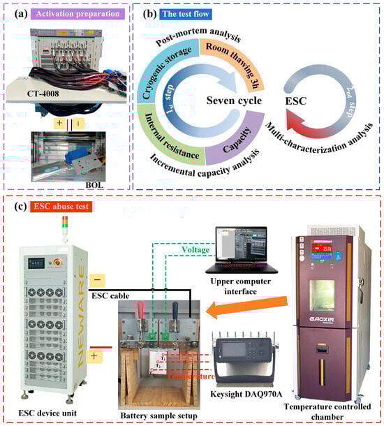
Figure 1.
Experimental arrangements: (a) preparation for battery sample pre-activation; (b) workflow for experimental procedures; (c) schematic representation of the ESC apparatus.

Table 1.
Specific parameters of the low-temperature storage-tested LFP pouch batteries.
2.2. Experimental Workflow and Apparatus
The experimental framework of this study comprised two test program steps: a battery intermittent low-cryogenic storage performance characterization experiment and an ESC test. The first step aimed to quantitatively assess the impact of low-temperature storage on battery performance, with post mortem analysis employed for cross-validation. The second step mainly explored the behavior of thawed batteries after triggering the ESC. The test flow was depicted in Figure 1b.
2.2.1. Low-Temperature Storage Experiments of Batteries
To maintain a desired temperature (e.g., the low temperature, −35 °C), the battery was set within a Gaoxin programmable constant-temperature explosion-proof chamber (Dongguan Gaoxin Testing Equipment Co., Ltd., Dongguan, China). The target temperature was monitored and set via the touch panel. It is important to highlight that the batteries underwent a standard charge/discharge procedure to reach 100% SOC before being exposed to cryogenic conditions. The selection of 100% SOC is primarily based on the following reasons: Firstly, this state simulates common real-world scenarios where batteries are stored after being fully charged, such as electric vehicles parked outdoors during winter. Secondly, from a safety evaluation perspective, a high SOC corresponds to a high chemical potential and relatively lower thermal stability of the battery. Conducting abuse tests, such as external short circuits, after storage under these conditions can more effectively reveal the critical boundaries of its thermal safety risks, representing a typical validation under rigorous operating conditions. The batteries were equilibrated at the target ambient temperature for 48 h, followed by thawing at RT prior to undergoing a reference performance test (RPT). The battery RPT test consists of a room-temperature static capacity test (SCT) and the pulse-relaxation internal resistance test [32]. The capacity test involved two consecutive fully charged and discharged cycles. The test step setting is the same as the battery sample pre-activation procedure, with a 10 min rest between the steps. The 2nd discharge value was deemed to be the aged battery’s current capacity. Each battery underwent seven complete freeze–thaw cycle tests. The selection of this cycle count aims to simulate the number of intermittent temperature fluctuations that a battery might experience during a typical mid-cold season (approximately 1.5–2 months) in Northwest China in order to assess cumulative changes in the performance and material state. This number is considered sufficient for capturing key evolutionary trends induced by repeated freeze–thaw cycles while ensuring the feasibility and completeness of the experiment within practical limits. A single 48 h storage duration is designed to simulate real-world scenarios where batteries experience sustained low-temperature weather (e.g., 2–3 days) or typical short-term parking periods (e.g., a weekend spanning 48–60 h). The batteries underwent an incremental capacity (IC) analysis before and after the intermittent low-temperature storage cycles (0th and 7th) to evaluate battery aging patterns, using a small current of 1/12C. Each condition was tested for repeatability, with a minimum of three repetitions. This setup ensured the statistical data’s accuracy and mitigated deviations stemming from battery inconsistency. Subsequently, the disassembled samples were transferred through a commercial sample transfer bag to an SEM for visual inspection and micromorphological analyses of the electrodes. During this process, there was no more than one minute of exposure to air.
To simplify notation, a fully charged battery is abbreviated as FCB, with the subscript indicating the battery stored at low temperature (e.g., FCB−10 for a fully charged battery stored at −10 °C). To ensure accurate comparison, these processes were similarly repeated in a 25 °C environment to serve as a comparison condition. The arrangement of the experimental procedure and battery nomenclature is depicted in Table 2.
Table 2.
Test matrix for low-temperature aging experiments and the battery definition.
2.2.2. Simulated ESC (High-Rate) Experiment
In ESC situations, the current served as a crucial parameter reflecting the internal energy release and heat generation within the battery. Therefore, this experiment was carried out by applying the short-circuit current to provide a consistent current pathway, thereby achieving uniform local current density during battery electrode discharge [33,34]. This method enables a more comprehensive assessment of the impact of varying degrees of ESC severity on battery performance. To assess the propensity of batteries for leakage, explosion, or thermal runaway after low-temperature storage, simulated ESC (high rate) tests were conducted on thawed batteries at 25 °C using the short-circuit current at 20C and 50C, as presented in Table 3. Although low-resistance short circuits are unlikely in real-world systems, this test method is valuable for defining safety limits and evaluating storage impacts. Key results like temperature rise rates and venting data provide critical references for BMS fault diagnosis and protection strategies. Furthermore, as a benchmark (control sample), identical experiments were conducted on FCB25 batteries. The experimental execution was replicated twice for each condition, thus enhancing the reliability of the outcomes.
Table 3.
The ESC experimental arrangement.
The configuration of the ESC experimental setup is displayed in Figure 1c, which includes a signal circuit connector, a controlled thermostat chamber, a data logger, and a high-speed pulse testing system. Time was utilized as the condition for terminating the ESC, with a duration set at 1.25 times the time required for the chosen discharge current. This ensures consistent testing duration for fair comparisons of battery behavior and cumulative effects, focusing on response differences over the same timeframe. For instance, the theoretical discharge time for 20C was estimated to be 180 s; however, it was adjusted to 225 s to ensure a more adequate short-circuit duration. The time and short-circuit rate of the tests were precisely set by the host computer and its integrated Neware battery testing system software (BTSDA 8.0.0.477). Throughout the ESC process, the terminal voltage and current of the batteries were monitored and documented with the CE-6000 Neware BTS (Neware Technology Limited, Shenzhen, China). Three K thermocouples (T1, T2, and T3) were attached to the battery’s surface (Figure 1c) to monitor external macroscopic temperature variations. The test battery was vertically secured using a custom-made clamp to maintain uniform heat transfer conditions on all sides of the battery. This also ensured minimal temperature signal disturbances. Additionally, temperature monitoring persisted for a minimum of 3 min following the conclusion of the test, aimed at capturing the full signal of temperature variation subsequent to battery failure. A camera was positioned inside an explosion-proof chamber at a 10 cm distance from the test battery, and we attempted to capture visual observations and audio intensity evolution during the ESC process.
3. Results and Discussion
3.1. Electrochemical Performance Prior to and After Low Temperature and RT
Battery performance was evaluated based on impedance and capacity before and after low-temperature storage. Figure 2 shows the voltage profiles and capacity tendency of the LFP batteries after periodic storage at different temperatures (25 °C, −10 °C, and −35 °C). Following the low-temperature storage condition, the actual maximum discharge capacity is obtained at RT. As shown in Figure 2a,c,e, there was significant overlap between the discharge curves of the thawed battery and the fresh battery. Minimal differences were observed before the discharge capacity exceeded 2.5 Ah. This made it difficult to differentiate the influence of the low temperature. After 14 days of intermittent storage at 25 °C, a capacity loss of 0.02 Ah was observed despite the low self-discharge rate of the LFP battery, indicating a gradual decline in performance. The extent of calendar aging in Li-ion batteries escalates in correlation with the duration of storage. During this time, ongoing side reactions led to a gradual loss of the Li+. This depletion directly contributed to a steady decline in capacity. An unexpected phenomenon was observed in the LFP batteries stored at −10 °C and −35 °C: a marginal capacity enhancement. This contrasts with the typical expectation of capacity degradation under such conditions. After the first 48 h, capacities increased by 0.04 Ah and 0.06 Ah, as shown in Figure 2d,f, respectively. The phenomenon was also mentioned in the study by Sun et al. [20]. The function of the anode suspension zone in combination with low-temperature storage conditions has been attributed to this phenomenon. During the charging process, part of the Li+ migrated to the anode suspension zone and was not fully utilized [35,36,37]. Under low-temperature storage conditions, Li+ was stably retained in the anode suspension zone, and side reactions and deposition phenomena were minimized. Cyclic thawing improved electrolyte wetting and promoted Li+ diffusion. Consequently, an escalation in the kinetic energy of chemical reactions within the pouch battery occurred. As a result, the previously underutilized Li+ was released, resulting in an observed rebound in capacity. Based on the results above, combined with the studies by Sun [20] and Maik [37], it is indicated that low-temperature storage has a positive impact on inhibiting battery self-discharge and reducing the occurrence of side reactions within the battery.
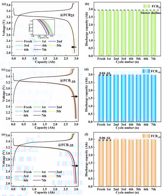
Figure 2.
Voltage profiles and capacity trends of LFP batteries after intermittent storage. Storage of 100% SOC batteries at 25 °C (a,b), −10 °C (c,d), and −35 °C (e,f).
The experimental set incorporated 4–5 battery samples per experimental condition to augment the reliability of the findings under a spectrum of storage environments. As illustrated in Figure 3, statistical analysis of the battery degradation patterns under diverse storage conditions indicated a correlation between battery decline and surrounding conditions and the number of low-temperature storage cycles. It was found that 100% SOC Li-ion batteries lose their capacity with increasing storage duration at 25 °C. This decrease was consistent with the changes in the battery discharge curves shown in Figure 2a. Under storage conditions of −10 °C, the Li-ion batteries showed an initial increase in capacity, which lasted until the seventh storage cycle, at which point the capacity began to decline by 0.04 Ah. Conversely, the initial performance at −35 °C was analogous. The battery capacity exhibited a notable stability across the subsequent storage cycles. As shown in Figure 3a–c, the standard deviation of the maximum usable capacity of the batteries was lower than 0.04 Ah, 0.03 Ah, and 0.05 Ah at 25 °C, −10 °C, and −35 °C, respectively, indicating a high degree of consistency. Extensive multi-sample assessments have demonstrated that, in Li-ion batteries operating at 100% SOC, the rate of self-discharge is markedly reduced as the ambient storage temperature is lowered. Based on the short-term storage (48 h) observations in this study, the −35 °C storage condition demonstrated the least suppression of initial capacity fade and even showed a slight capacity recovery phenomenon.
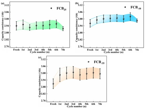
Figure 3.
Study of battery capacity consistency with storage times under different temperature storage conditions: (a) 25 °C, (b) −10 °C, and (c) −35 °C.
After the storage periods, the internal resistance of the thawed battery was evaluated using the pulse relaxation method, as shown in Figure 4. A slight decrease in the ohmic internal resistance (Ro) of 1.59 mΩ with an increasing number of storage cycles was observed for batteries stored at 25 °C (Figure 4a,b). The Rp showed a more pronounced decrease of around 24.28 mΩ. After carrying out seven storage cycles at −10 °C and −35 °C, a slight increase in the Ro of the battery was observed. Specifically, the Ro increased by 1.61 mΩ and 0.43 mΩ at −10 °C and −35 °C conditions, respectively, as shown in Figure 4c,e. The polarization effect of the battery was significantly influenced by the depth of discharge (DOD), which gradually increased with increasing discharge depth, as shown in Figure 4d,f. This trend was particularly pronounced towards the end of the discharge cycle. The Rp of the FCB−10 and FCB−35 batteries showed a significant increase, reaching 32.00 mΩ and 21.06 mΩ, respectively. It can be seen that both storage temperature and discharge depth significantly affect the IR of Li-ion batteries. This performance reduction is likely due to the substantially increased electrolyte viscosity at low temperatures, which blocks ion migration. Upon thawing, ohmic resistance (Ro) recovers relatively quickly. In contrast, polarization resistance (Rp) exhibits a slower recovery. Therefore, for batteries after low-temperature storage, extending the thawing time before reactivation is necessary.
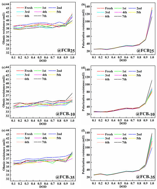
Figure 4.
The internal resistance analysis of batteries during the storage process. (a,c,e) Ohmic resistance; (b,d,f) polarization resistance.
The changes in internal resistance of different thawed batteries at DODs of 0.5, 0.8, and 1.0 are shown in Figure 5a–c. Figure 5d also showed the average incremental change in internal resistance of multiple samples after seven intermittent storage periods relative to the initial internal resistance. At the three temperature conditions of 25 °C, −10 °C, and −35 °C, the Ro of the batteries remained essentially constant from pre-freezing to post-storage. It can be visualized from Figure 5a to c that the increase in total internal resistance (Rt) at low temperatures was mainly due to the change in Rp. Notably, the pronounced Rp occurs at a depth of 1.0, stemming from heightened ion concentration gradients and internal reaction diffusion barriers during deep discharge. Additionally, the rise in charge transfer impedance is linked to surface film development or degradation on electrodes. Prolonged deep discharges can lead to physicochemical alterations in electrode materials, such as structural degradation, consequently affecting Rt. Storage tests at 25 °C showed a 12.86% decrease in Rp after more than 14 days and 7 cycles (Figure 5d). A similar decreasing trend in internal resistance was also observed for LiFePO4|Graphite batteries by Lewerenz et al. [35]. This implies that calendar aging is minimal at 25 °C. As depicted in Figure 5d, the Rp of the battery exhibited a more pronounced increase under the low-temperature storage condition at −10 °C. After 14 days of intermittent storage, the average increase in Rp was 40.57 mΩ. In contrast, at −35 °C, the average increase in Rp was 16.82 mΩ. This indicated that the effect of low temperatures on Rp was significant. To summarize, the relatively smaller change in internal resistance and capacity at −35 °C meant that the performance of the battery was more stable.
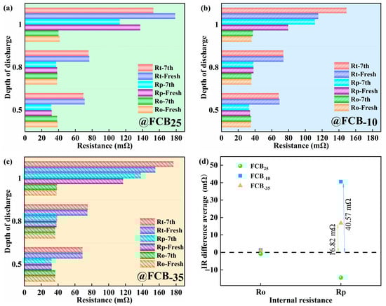
Figure 5.
Effect of discharge depth on internal resistance of (a) battery FCB25, (b) battery FCB−10, and (c) battery FCB−35 and (d) average value of Ro and Rp increase before and after the battery samples were stored at different temperatures.
3.2. Analysis of Li-Ion Battery Internal Material State Before and After Intermittent Freezing Process
The dQ/dV profile predominantly captures the phase transitions within both anode and cathode active materials throughout battery operation, which could qualitatively deduce the intrinsic mode of the capacity degradation of Li-ion batteries [38]. The LiFePO4 cathode material exhibits an olivine-type crystal structure. Its charge and discharge processes are primarily characterized by the reversible intercalation and deintercalation of lithium ions between the two phases of LiFePO4 and FePO4, accompanied by the redox reaction of the Fe2+/Fe3+ couple. The incremental capacity curve of Li-ion pouch batteries before and after 14 days of intermittent storage at 25 °C, −10 °C, and −35 °C is shown in Figure 6. To minimize the polarization effects as much as possible, 1/12C was used in this process. During the charging and discharging process, carbon, the anode material, goes through five different reaction stages, culminating in the formation of LiC6. On the other hand, the anode reacts mainly through a non-stoichiometric single-phase solid solution phase at both ends and an intermediate pseudo-binary first-order phase transition process. The characteristic peaks of FePO4 and LiFePO4 in the terminal phase region of the battery are not observed in Figure 6, indicating that the electrochemical reactions in these regions are weak. The changes in peaks I and II before and after storage were mainly characterized by different degrees of broadening, which may imply slower ion diffusion or electron transfer in the material. At room temperature, the intensity of peak II decreased by 13,707 mAh/V before and after storage, indicating a gradual decrease in the activity of the properties of the material, consistent with the slight decrease in capacity during storage. The shift to high-voltage characteristic peaks after low-temperature storage indicates an increase in the internal impedance of the battery and the loss of active Li+ [39]. In particular, storage at −10 °C and −35 °C resulted in shifts in intensity characteristic peaks I and II by about 0.002 V (Figure 6c) to 0.007 V (Figure 6b).
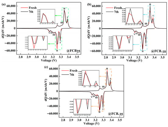
Figure 6.
Incremental capacity analysis of LiFePO4 batteries before and after storage at (a) 25 °C, (b) −10 °C, and (c) −35 °C.
The electrochemical performance of the batteries exhibited notable variations across various low-temperature storage conditions, indicating that intermittent low-temperature exposure adversely impacts battery performance. Visual inspection of the exterior of the battery before and after low-temperature storage did not reveal any obvious dents, cracks, or pits. Presumably, the internal material structure and surface composition of the battery have deteriorated; a post mortem of the battery was deemed necessary for a comprehensive understanding of the effects of intermittent low temperatures [19]. The battery was disassembled in an argon-dry environment. During this process, it was observed that the electrolyte inside the battery was evenly distributed, the separator remained intact, and the adhesion of the current collector was normal. Visual inspection did not reveal any anomalies such as separator pierce, material delamination, or edge shorting that might have been caused by low-temperature storage and subsequent thawing processes. Then, electrodes were extracted from the battery and subjected to surface structural analysis using an SEM and XRD. Three randomly selected positions of the battery electrode were analyzed to mitigate potential sampling position interference, ensuring the reliability of the results. The SEM results of the LFP and graphite materials are shown in Figure 7a. It could be seen that storage at different temperatures did not cause any visible damage to the cathode electrode of the battery, while the low-temperature-induced damage was more obvious on the anode electrode’s structure. While quantitative analyses of crack density and particle size could better quantify damage, our qualitative observations clearly show damage distributions linked to storage conditions, providing direct microstructural evidence for the increased polarization resistance. Typical electrolytes freeze gradually from approximately −20 °C to 60 °C [40], and it was hypothesized that the phase change process caused by the constant freezing–thawing of the electrolyte caused a number of effects when a low-temperature environmental response is encountered. This may include changes in electrolyte volume, redistribution after thawing, and stress deformation or rupture of the anode graphite particles to accommodate the frozen electrolyte. The observed Rp increase shows qualitative consistency with anode damage, and the mechanism based on material behavior strongly supports this conclusion. Together, these factors contributed to the low-temperature-induced damage of the battery anode material [41]. In addition, the presence of a surface covering layer on the anode material as a result of low-temperature storage may also contribute, to some degree, to the increase in the internal resistance of the battery. The significant increase in polarization resistance observed in this study results from the combined effects of interfacial and transport processes. Low temperatures and freeze–thaw cycles likely degrade the charge transfer kinetics at the electrode interface, while changes in electrolyte properties and damage to the electrode microstructure (e.g., anode cracking) exacerbate lithium-ion transport limitations. Although more detailed electrochemical impedance spectroscopy (EIS) analysis could further quantify the contributions of each sub-process, macroscopic performance testing combined with microscopic morphological characterization confirms that the performance degradation induced by low-temperature storage is primarily related to interfacial and structural evolution on the anode side. The morphological evolution of the cathode and anode lattice structures is observed, as characterized by XRD analyses in Figure 7b,c. No substantial shifts were observed in the crystal plane positions for both anode and cathode electrodes based on the measurements. Post-storage at low temperatures, the LFP’s diffractive intensity remains stable, contrasting with the diminished graphite anode peaks, potentially due to particle fragmentation and surface by-product accumulation. As shown in Figure 7d, an energy-dispersive spectrometer (EDS) is further used to detect the elemental composition of the graphite anode’s surface, in addition to the presence of C, O, F, and P elements, focusing on the detection of the presence of Fe elements. This proves that there was no internal dissolution of cathode Fe elements during the intermittent storage of the battery. It also further indicated that the separator was kept intact during the whole process. Peak fitting or deconvolution analysis of the incremental capacity (IC) curve can quantify the respective contributions of the cathode and anode to overall capacity degradation, providing a refined tool for investigating competing degradation mechanisms in future studies. Here, combined with direct electrode characterization via SEM, XRD, and EDS, the performance degradation is primarily attributed to anode interfacial and structural changes.
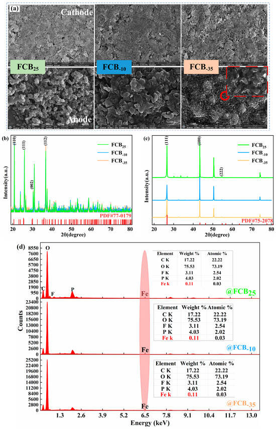
Figure 7.
(a) SEM images of the magnifications of the aged cathode and anode; the XRD results analysis of the aged cathode (b) and anode (c); (d) EDS analysis of the anode electrode.
3.3. Safety Behaviors of Thawed Batteries After Intermittent Low-Temperature Store
Li-ion batteries that had previously been stored at a range of temperatures were transferred to an ambient environment of 25 °C and then subjected to ESC tests at 20C and 50C, respectively. In this section, the first focus was on the typical electrical and thermal behavior of Li-ion batteries under ESC conditions. Subsequently, a comprehensive comparative characterization of thawed batteries was performed. Moreover, there was a focus on key parameters, including voltage variations, temperature evolutions, and mass losses when subjected to ESC.
The 20C ESC experiments were performed on 100% SOC Li-ion batteries, which suffered seven cycles of storage at 25 °C. Typical signal characteristics, including voltage, temperature, short-circuit current, and SOC, are shown in Figure 8. Upon triggering an ESC, Li+ in the solid–liquid phase within the battery rapidly reacts with electrodes. Consequently, the short-circuit current rapidly increased to approximately 60 A and then gradually declined to less than 1 A after 220 s. This continuous decline in current was typically associated with chemical reactions and physical alterations occurring within the battery. High-current discharge during ESC causes a sharp increase in the internal heat of the battery. Subsequently, the separators partially closed and filled the pores, thereby reducing the battery’s discharge capability [42]. In the end stage of ESC, the depletion of the electrolyte within the battery and mechanical breakage instantly resulted in a large quantity of side reaction products spraying out. This increased the internal transmission impedance and restricted lithium diffusion. A significant voltage drop is a key indicator of an external short circuit (ESC). Upon ESC triggering, this voltage anomaly occurs almost immediately (typically within 1 s). As shown in Figure 8a (red line), the terminal voltage rapidly drops from 3.41 V to 1.15 V and continues to decline, eventually approaching 0 V by the end of the test. The initial voltage drop of the battery is primarily associated with the internal ohmic resistance. During the experimental process, no fused tag phenomenon was observed. The pouch battery utilized in the experiment contains no circuit protection device. Consequently, the continuous voltage drop was mainly attributed to the internal heat-induced damage to the electrolyte film, which led to the blockage of ion transport [43]. The SOC of the battery initially decreased linearly, following physical breakage at a slow pace. This is correlated with the battery current’s change. The thermal response lags behind the electrical signal, manifesting a generally exponential rise [44]. Analyses of temperatures at different monitoring points revealed that the temperature response was quicker near the anode tag. In contrast, the center battery surface temperature (T2) tends to be comparatively lower. During the 20C ESC process, the temperature difference between different locations may reach over 10 °C, and the battery reached a maximum temperature of 106.10 °C. This temperature discrepancy can be attributed to two main factors. First, internal side reactions and gas generation interfere with accurate surface temperature measurement. Second, uneven current distribution and internal heat dissipation conditions within the battery itself lead to localized temperature variations [45]. Figure 8a illustrates the onset of T1 decline at 82 s. At this point, the internal pressure of the battery surpassed the sealing pressure of the pouch battery, causing high-temperature gas to accumulate and the battery to eventually rupture. As this happened, the accumulated heat inside was rapidly dissipated, causing the surface temperature of the battery to drop. As depicted in Figure 8b, accompanied by a distinct sound, white smoke was clearly visible emanating from the vicinity of the battery’s cathode lugs and dispersing into the surrounding environment. Although the aluminum–plastic shell breakage of the battery effectively prevented violent thermal runaway within the battery, the gases released are still a potential hazard that needs to be considered. This investigation did not extend research to an analysis of the precise gaseous constituents. However, based on the temperature values obtained during the experiment and the obvious pungent odor when the chamber was opened at the end of the experiment, it is presumed that they mainly consist of flammable, toxic, and potentially explosive gas–liquid mixtures such as CO2, CO, C2H4, etc., as observed by Yang et al. [46]. The accurate identification of gas species and quantification of gas generation rates require follow-up studies equipped with advanced diagnostic tools such as online mass spectrometry or gas chromatography.
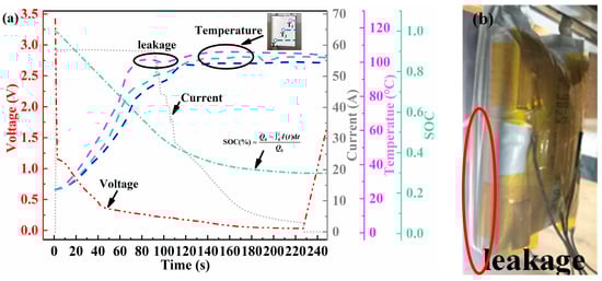
Figure 8.
Electrothermal characteristics of battery FCB25 subjected to a 20C ESC in an RT environment. (a) Voltage (red line), current (grey line), SOC (green line), and temperature (purple, light blue, and blue lines); (b) short-circuited battery leakage phenomena.
To accurately compare and analyze the impacts of different temperature storage conditions on the signal characteristics of subsequent ESC tests, 20C and 50C short-circuit tests were carried out on thawed batteries that had been subjected to three different intermittent store temperatures. Figure 9 presents a comparison of the various characteristic signals, encompassing short-circuit voltage response, discharge capacity, the temperature at the center point over time, and the temperature rise rate. Upon obtaining the experimental data shown in Figure 9a, the initial voltages of batteries FCB25, FCB−10, and FCB−35 dropped to 1.16 V, 1.22 V, and 1.12 V, respectively, after being subjected to ESC testing at 20C. The instantaneous voltage sharply dropped to approximately 0.44 V–0.49 V at 50C. The initial voltage reductions attributed to ESC are predominantly a result of the battery’s ohmic resistance losses. Interestingly, the change in battery Ro before and after low-temperature storage was minimal (shown in Figure 5d), indicating that the difference in the initial voltage drop for the initial voltage of ESC does not stem from low-temperature environments but rather from the characteristics of the batteries themselves. Although the initial voltage drop varied slightly from battery to battery, the overall trend was the same, and the voltage fluctuated in the later stages of the ESC. This is because the high currents generated by the ESC led to non-uniform current density and temperature distribution within the battery, as well as localized nonlinear damage [47].
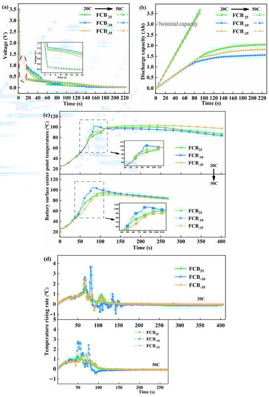
Figure 9.
Electrochemical behavior changes in different thawed batteries under 20C and 50C discharge current rates for comparison. (a) Voltage profiles, (b) discharge capacities, (c) T2 temperature changes, and (d) temperature increment rate.
The discharge capacity of a Li-ion battery under ESC is depicted in Figure 9b. It was found that an enhancement in the rate of discharge resulted in a prompt increase in discharge capacity during the ESC process. This capacity was calculated by integrating the current. To comprehensively monitor the entire process of failure, experiments were conducted with ample testing duration, allowing the battery to undergo over-discharge at the end of the ESC. At 50C, the theoretical discharge capacity of the battery exhibited a linear increase, reaching approximately 3.57 Ah. This phenomenon was consistent across various thawed batteries, indicating severe battery damage at this stage. Conversely, at a 20C short-circuit condition, batteries stored under different temperature conditions displayed significant variations. The data demonstrated a nonlinear trend with regard to discharge capacity during the ESC process, with the capacity being limited at around 1.80 Ah. This was related to the slowing down of the internal current drop during the later stages of the 20C short circuit.
The temperature–time curves for the center point of thawed batteries FCB25, FCB−10, and FCB−35 during the ESC are illustrated in Figure 9c. During the ESC process, the temperature of Li-ion batteries consistently increased, with peak temperatures typically observed following electrolyte leakage. This suggested that ESCs may initiate abusive side reactions within the internal materials: notably, a higher short-circuit rate with a more rapid temperature rise. However, the peak temperature at T2 reaches a comparatively low value because of the brief duration of the short-circuit event. During the initial phase of ESC abuse, a uniform rate of temperature rise was observed across all batteries, as depicted in Figure 9d. Hypothetically, in the absence of detrimental impacts from low-temperature storage on the batteries, it is anticipated that the thermal response of the three batteries will maintain a uniform rate of temperature escalation throughout the experimental protocol. In fact, the FCB−10 battery reached a temperature rise rate of 1.02 °C/s approximately 55 s after suffering 20C ESC and a maximum temperature rise rate of 3.67 °C/s. At 50C, this critical time was advanced to 45 s. Throughout the temperature parameters of the battery, FCB−10 changes the fastest, with FCB25 following and FCB−35 being the slowest. As shown in Figure 9c, the maximum temperatures at the center of the FCB−10, FCB25, and FCB−35 batteries’ surfaces were 104.35 °C, 94.67 °C, and 90.56 °C when suffering the 50C ESC fault, respectively. Based on earlier Rp analysis (Figure 5), the FCB−10 group with the largest Rp rise after low-temperature storage showed the fastest temperature rise during ESC (Figure 9d). This can be explained by Joule heating: A higher Rp directly increases polarization-related heat generation and may concentrate heat at the interface due to worsened electrode kinetics. Additionally, low-temperature storage can modify the internal electrochemical state of the cell by suppressing ion transport kinetics and inducing interfacial evolution. After subsequent activation cycling, these changes would result in increased internal resistance and electrochemical polarization, which in turn promote more rapid voltage collapse and intensified heat generation during an external short circuit.
The mass loss of Li-ion batteries stored at different temperatures during ESC is summarized in Table 4. Notably, while the discharge rate and experimental duration were held constant across tests, the data revealed a significant variance in mass loss among batteries. In Table 4, the weight loss of batteries FCB25, FCB−10, and FCB−35 at 20C was 8.19 g, 8.72 g, and 8.83 g, respectively, with an overall difference of 0.64 g. The loss constituted approximately 8.59% to 9.26% of the batteries’ total mass, predominantly resulting from solvent evaporation and electrolyte leakage. Comparatively, the mass loss of these batteries was 4.19 g, 3.70 g, and 0.50 g, respectively. Under the 50C short circuit, FCB−35 shows much lower mass loss than others (Table 4), with delayed/minimal leakage (Figure 10). This suggests insufficient gas pressure for casing rupture, likely due to less structural damage after low-temperature storage and slower gas-generating side reactions. Short-circuit durations critically affect cumulative heat and failure severity—longer times can raise peak temperatures and intensify failures. Our conclusions on ESC behavior differences across storage temperatures are specific to the tested time window.
Table 4.
The ESC mass loss.

Figure 10.
Sound intensity leakage during the ESC process of thawed batteries and the resulting battery appearance.
Figure 10 contains the moment of physical breakage, the duration of the leakage, and the visual representation of the battery’s condition. Regardless of the degree of ESC of the battery under test, the overall damage level of the battery satisfies FCB−10 > FCB25 > FCB−35. It can be seen from Figure 10 that the FCB−10 battery subjected to ESC displayed an early onset of leakage and the most pronounced leakage tone intensity, but its leakage duration was comparatively shorter. During the 20C ESC process, the battery FCB−10 rupture occurred at approximately 72 s, with a leakage duration of 58 s. The breakage moment during the 50C ESC process was advanced to 47 s, and the duration was about 28 s. Battery FCB−35 showed the latest onset of leakage under 20C ESC conditions. Then, it had the longest leakage time, which led to the greatest mass loss. This phenomenon was noted alongside the slow battery temperature drop observed in Figure 9c, where the battery leakage was relatively slow, resulting in less overall heat exchange with the environment. The inset of Figure 10 showed that the batteries did not rupture in the same location. The appearance of battery FCB−35 under 50C ESC conditions showed a clear difference. The observed phenomenon may stem from the fact that battery FCB−35 did not generate sufficient internal heat during the 50C ESC process to produce significant gas emissions. Under this 50C abuse condition, battery FCB−35 exhibited no signs of rupture, or the opening was minimal, leading to negligible amounts of gases and electrolyte leakage. So, the battery did not show internal air pressure phenomena similar to other battery short circuit conditions.
Figure 11 presents a comprehensive comparison of performance and ESC test results for batteries stored at different temperatures. The analysis focused on five key parameters: internal resistance following intermittent storage, initial voltage drops under uniform ESC conditions, leakage moment, leakage duration, and peak temperature. In addition, the battery capacity data was also a critical parameter, which was compared in Figure 3. In conclusion, the batteries after storage at different temperatures showed significant variability. Specifically, the Rt of the batteries exhibited a notable increase following exposure to −10 °C low-temperature storage conditions. When considering the parameters related to ESC, all three batteries displayed similar initial voltage drops at the same level of ESC fault. This further supported the conclusion that temperature variations have a minimal impact on the Ro of the batteries. Battery FCB−10‘s seal rupture moment was advanced with a noticeable leakage sound, and an abnormal increase in temperature during the ESC process could also be observed (Figure 9c). As a comparison, the short-circuit temperature rise of the FCB−35 battery was not significantly different from that of a room-temperature shelved battery, the leakage time was delayed by 6–10 s compared to that of a room-temperature stored battery, and the leakage sound intensity was smaller.
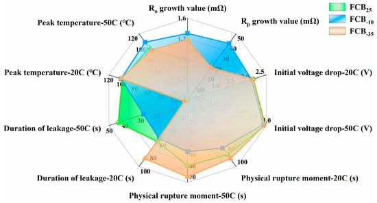
Figure 11.
Comprehensive comparison of performance and ESC test results for batteries stored at different temperatures.
4. Conclusions
This paper presents a comprehensive examination of the impact of various temperature storage conditions on the electrical performance and ESC safety characteristics of commercially available 3 Ah pouch Li-ion batteries. The batteries were stored at 25 °C, −10 °C, and −35 °C for 48 h, with each battery undergoing seven such cycles before ESC tests. The electrochemical properties and short-circuit safety variations of multiple battery samples consistently demonstrated good reproducibility:
- (1)
- Following seven storage cycles at 25 °C, we observed a 12.86% reduction in Rp in 100% SOC batteries, with a concurrent 0.71% decrease in actual capacity. Conversely, within the first 48 h of storage, FCB−10 and FCB−35 batteries exhibited a capacity increase of 1.2% to 2.05%. The average Rp of FCB−10 batteries increased by 40.57 mΩ, whereas at −35 °C, internal resistance increased marginally by 16.82 mΩ. Notably, the Ro of the batteries remained constant throughout the storage process across all tested temperatures.
- (2)
- Visual inspection of the exterior of the battery before and after low-temperature storage did not reveal any obvious dents, cracks, or pits. Exposure to low temperatures under test conditions primarily causes breakage of the anode material. Low-temperature storage induced a significant occurrence of electrolyte layer and particle cracking within the anode structure. In contrast, the cathode retained characteristics similar to its pristine state, a finding confirmed by XRD analysis. EDS analyses revealed the absence of iron on the anode electrode surface, suggesting that the anode and separator remained intact during low-temperature storage.
- (3)
- The decline in initial short-circuit terminal voltage is predominantly controlled by the ESC’s severity and is relatively insensitive to the temperatures at which the batteries were ever stored. After low-temperature storage, FCB−10 batteries exhibited a higher heat release rate of up to 2.78 °C/s, hastened physical damage at around 47 s into the 50C ESC, and increased leakage intensity over FCB25. In contrast, FCB−35 batteries experienced a significant delay in ESC leakage initiation and a reduced peak temperature of 90.56 °C, indicating mitigated ESC-induced damage. Low-temperature storage alters LFP battery responses under external short-circuit abuse, leading to differences in temperature rise rates and venting behavior. This affects safety-response evolution and may influence susceptibility to severe failure modes like thermal runaway.
Author Contributions
F.G.: Funding acquisition, investigation, methodology, writing—original draft; D.Q.: supervision, resources, and methodology; Y.B.: methodology and resources; Z.Z.: methodology and resources; Y.G.: data curation, and formal analysis; W.L.: conceptualization, supervision, and writing—review and editing; R.J.: investigation and methodology. All authors have read and agreed to the published version of the manuscript.
Funding
This research received no external funding.
Data Availability Statement
The raw data supporting the conclusions of this article will be made available by the authors upon request.
Conflicts of Interest
Authors Feng Gao, Yanping Bai, and Yechang Gao were employed by the State Grid Gansu Electric Power Company. Authors Desheng Qiang, Zongliang Zhai, and Weixing Lu were employed by Gansu Chengxin Electric Power Technology Co., Ltd. The remaining authors declare that the research was conducted in the absence of any commercial or financial relationships that could be construed as a potential conflict of interest. The authors declare that they have no known competing financial interests or personal relationships that could have appeared to influence the work reported in this paper.
Abbreviations
| LFP | LiFePO4 |
| FCB | Fully charged batteries |
| IR | Internal resistance |
| SEM | Scanning electron microscopy |
| XRD | X-ray diffraction |
| Rp | Polarization resistance |
| RT, 25 °C | Room temperature |
| ESC | External short circuit |
| SEI | Solid electrolyte interphase |
| NMC | Nickel manganese cobalt |
| SOC | State of charge |
| NCA | LiNi0.8Co0.15Al0.05O2 |
| RPT | Reference performance test |
| SCT | Static capacity test |
| IC | Incremental capacity |
| Ro | Ohmic internal resistance |
| DOD | Depth of discharge |
| Rt | Total internal resistance |
| EDS | Energy-dispersive spectrometer |
| ESCs | External short circuits |
References
- Liu, Y.H.; Zhang, L.; Huang, X.J.; Hao, M.L.; Huang, X.Y. Laser-induced thermal runaway dynamics of cylindrical lithium-ion battery. J. Energy Storage 2024, 86, 111337. [Google Scholar] [CrossRef]
- Ding, L.; Li, D.D.; Du, F.H.; Zhang, D.X.; Zhang, S.H.; Xu, R.Z.; Wu, T. Mechanical behaviors and ion transport variation of lithium-ion battery separators under various compression conditions. J. Power Sources 2022, 543, 231838. [Google Scholar] [CrossRef]
- Xu, C.S.; Wang, H.B.; Jiang, F.C.; Feng, X.N.; Lu, L.G.; Jin, C.Y.; Zhang, F.S.; Huang, W.S.; Zhang, M.Q.; Ouyang, M.G. Modelling of thermal runaway propagation in lithium-ion battery pack using reduced-order model. Energy 2023, 268, 126646. [Google Scholar] [CrossRef]
- Jia, Y.K.; Darst, J.; Surelia, A.; Delafuente, D.; Finegan, D.P.; Xu, J. Deformation and fracture behaviors of cylindrical battery shell during thermal runaway. J. Power Sources 2022, 539, 231607. [Google Scholar] [CrossRef]
- Hu, X.; Zhang, K.; Liu, K.; Lin, X.; Dey, S.; Onori, S. Advanced Fault Diagnosis for Lithium-Ion Battery Systems: A Review of Fault Mechanisms, Fault Features, and Diagnosis Procedures. IEEE Ind. Electron. Mag. 2020, 14, 65–91. [Google Scholar] [CrossRef]
- Su, L.; Zhang, J.; Wang, C.; Zhang, Y.; Li, Z.; Song, Y.; Jin, T.; Ma, Z. Identifying main factors of capacity fading in lithium ion cells using orthogonal design of experiments. Appl. Energy 2016, 163, 201–210. [Google Scholar] [CrossRef]
- Liu, J.; Zhang, Y.; Zhou, L.; Han, C.; He, T.; Wang, Z. Influencing factors of lithium-ion battery thermal runaway in confined space. J. Energy Storage 2023, 73, 109125. [Google Scholar] [CrossRef]
- Gupta, A.; Manthiram, A. Designing Advanced Lithium-Based Batteries for Low-Temperature Conditions. Adv. Energy Mater. 2020, 10, 2001972. [Google Scholar] [CrossRef] [PubMed]
- Zheng, Y.; Che, Y.; Hu, X.; Sui, X.; Stroe, D.-I.; Teodorescu, R. Thermal state monitoring of lithium-ion batteries: Progress, challenges, and opportunities. Prog. Energy Combust. Sci. 2024, 100, 101120. [Google Scholar] [CrossRef]
- Ren, D.; Hsu, H.; Li, R.; Feng, X.; Guo, D.; Han, X.; Lu, L.; He, X.; Gao, S.; Hou, J.; et al. A comparative investigation of aging effects on thermal runaway behavior of lithium-ion batteries. Etransportation 2019, 2, 100034. [Google Scholar] [CrossRef]
- Feng, X.; Ren, D.; Zhang, S.; He, X.; Wang, L.; Ouyang, M. Influence of aging paths on the thermal runaway features of lithium-ion batteries in accelerating rate calorimetry tests. Int. J. Electrochem. Sci. 2019, 14, 44–58. [Google Scholar] [CrossRef]
- Zhang, J.; Su, L.; Li, Z.; Sun, Y.; Wu, N. The Evolution of Lithium-Ion Cell Thermal Safety with Aging Examined in a Battery Testing Calorimeter. Batteries 2016, 2, 12. [Google Scholar] [CrossRef]
- Wang, Z.; Wang, J. An experimental investigation of the degradation and combustion behaviors associated with lithium ion batteries after different aging treatments. J. Clean. Prod. 2020, 272, 122708. [Google Scholar] [CrossRef]
- Zhang, L.; Liu, J.; Fan, P.; Du, L.; Ma, Y.; Qu, B.; Yin, G.; Fu, Q.; Yang, F.; Zhang, C. Unraveling the effect of short-term high-temperature storage on the performance and thermal stability of LiNi0.5Co0.2Mn0.3O2/graphite battery. J. Power Sources 2020, 459, 227842. [Google Scholar] [CrossRef]
- Nandini, K.; Usha, K.; Srinivasan, M.S.; Pramod, M.; Satyanarayana, P.; Sankaran, M. Study on survivability of 18650 Lithium- ion cells at cryogenic temperatures. J. Energy Storage 2018, 17, 409–416. [Google Scholar] [CrossRef]
- Grandjean, T.R.B.; Groenewald, J.; Marco, J. The experimental evaluation of lithium ion batteries after flash cryogenic freezing. J. Energy Storage 2019, 21, 202–215. [Google Scholar] [CrossRef]
- Sunderlin, N.; Colclasure, A.; Yang, C.; Major, J.; Fink, K.; Saxon, A.; Keyser, M. Effects of cryogenic freezing upon lithium-ion battery safety and component integrity. J. Energy Storage 2023, 63, 107046. [Google Scholar] [CrossRef]
- Grandjean, T.R.B.; Groenewald, J.; McGordon, A.; Marco, J. Cycle life of lithium ion batteries after flash cryogenic freezing. J. Energy Storage 2019, 24, 100804. [Google Scholar] [CrossRef]
- Li, J.; Li, S.; Zhang, Y.; Yang, Y.; Russi, S.; Qian, G.; Mu, L.; Lee, S.-J.; Yang, Z.; Lee, J.-S.; et al. Multiphase, Multiscale Chemomechanics at Extreme Low Temperatures: Battery Electrodes for Operation in a Wide Temperature Range. Adv. Energy Mater. 2021, 11, 2102122. [Google Scholar] [CrossRef]
- Sun, K.; Li, X.; Fu, K.; Yang, H.; Gong, L.; Tan, P. Extending the calendar life of LiNi0.8Co0.1Mn0.1O2-based lithium-ion batteries via low-temperature storage. Mater. Today Commun. 2024, 39, 108765. [Google Scholar] [CrossRef]
- Yu, Q.; Wang, C.; Li, J.; Xiong, R.; Pecht, M. Challenges and outlook for lithium-ion battery fault diagnosis methods from the laboratory to real world applications. Etransportation 2023, 17, 100254. [Google Scholar] [CrossRef]
- Galushkin, N.E.; Yazvinskaya, N.N.; Galushkin, D.N. Causes and mechanism of thermal runaway in lithium-ion batteries, contradictions in the generally accepted mechanism. J. Energy Storage 2024, 86, 111372. [Google Scholar] [CrossRef]
- Barai, A.; Uddin, K.; Chevalier, J.; Chouchelamane, G.H.; McGordon, A.; Low, J.; Jennings, P. Transportation Safety of Lithium Iron Phosphate Batteries—A Feasibility Study of Storing at Very Low States of Charge. Sci. Rep. 2017, 7, 5128. [Google Scholar] [CrossRef]
- Xiong, R.; Ma, S.; Li, H.; Sun, F.; Li, J. Toward a Safer Battery Management System: A Critical Review on Diagnosis and Prognosis of Battery Short Circuit. Iscience 2020, 23, 101010. [Google Scholar] [CrossRef]
- Chen, Z.; Xiong, R.; Lu, J.; Li, X. Temperature rise prediction of lithium-ion battery suffering external short circuit for all-climate electric vehicles application. Appl. Energy 2018, 213, 375–383. [Google Scholar] [CrossRef]
- Jaguemont, J.; Barde, F. A critical review of lithium-ion battery safety testing and standards. Appl. Therm. Eng. 2023, 231, 121014. [Google Scholar] [CrossRef]
- Zhou, X.; Wang, Z.; Sun, B.; Zhang, W.; Zhang, C.; Huang, Q.; Wang, S.; Yang, X.; Gong, H. Study of lithium-ion battery module external short circuit risk and protection design. J. Energy Storage 2024, 86, 111070. [Google Scholar] [CrossRef]
- Zhang, L.; Cheng, X.; Ma, Y.; Guan, T.; Sun, S.; Cui, Y.; Du, C.; Zuo, P.; Gao, Y.; Yin, G. Effect of short-time external short circuiting on the capacity fading mechanism during long-term cycling of LiCoO2/mesocarbon microbeads battery. J. Power Sources 2016, 318, 154–162. [Google Scholar] [CrossRef]
- Rheinfeld, A.; Noel, A.; Wilhelm, J.; Kriston, A.; Pfrang, A.; Jossen, A. Quasi-Isothermal External Short Circuit Tests Applied to Lithium-Ion Cells: Part I. Measurements. J. Electrochem. Soc. 2018, 165, A3427–A3448. [Google Scholar] [CrossRef]
- Chen, Z.-Y.; Xiong, R.; Zhang, B.; Yang, R.-X.; Shen, W.-X.; Yang, X.-G.; Sun, W.-Z.; Yu, D.-W.; Sun, F.-C. Benign-to-malignant transition in external short circuiting of lithium-ion batteries. Cell Rep. Phys. Sci. 2022, 3, 100923. [Google Scholar] [CrossRef]
- Xiong, R.; Sun, W.; Yang, R.; Sun, F. Damage and Failure Boundaries and Prediction of External Short Circuit in Lithium-ion Battery. J. Mech. Eng. 2023, 59, 113–124. [Google Scholar]
- Wu, H.; Zhang, X.; Cao, R.; Yang, C. An investigation on electrical and thermal characteristics of cylindrical lithium-ion batteries at low temperatures. Energy 2021, 225, 120223. [Google Scholar] [CrossRef]
- An, Z.; Shi, T.; Zhao, Y.; Gong, Q.; Zhang, D.; Bai, J.; Du, X. Study on aging and external short circuit mechanisms of Li-ion cells with different electrode thicknesses. Appl. Energy 2023, 350, 121796. [Google Scholar] [CrossRef]
- An, Z.; Zhao, Y.; Du, X.; Shi, T.; Zhang, D. Experimental research on thermal-electrical behavior and mechanism during external short circuit for LiFePO4 Li-ion battery. Appl. Energy 2023, 332, 120519. [Google Scholar] [CrossRef]
- Lewerenz, M.; Muennix, J.; Schmalstieg, J.; Kaebitz, S.; Knips, M.; Sauer, D.U. Systematic aging of commercial LiFePO4\Graphite cylindrical cells including a theory explaining rise of capacity during aging. J. Power Sources 2017, 345, 254–263. [Google Scholar] [CrossRef]
- Wilhelm, J.; Seidlmayer, S.; Keil, P.; Schuster, J.; Kriele, A.; Gilles, R.; Jossen, A. Cycling capacity recovery effect: A coulombic efficiency and post-mortem study. J. Power Sources 2017, 365, 327–338. [Google Scholar] [CrossRef]
- Naumann, M.; Schimpe, M.; Keil, P.; Hesse, H.C.; Jossen, A. Analysis and modeling of calendar aging of a commercial LiFePO4/graphite cell. J. Energy Storage 2018, 17, 153–169. [Google Scholar] [CrossRef]
- Zhu, J.; Darma, M.S.D.; Knapp, M.; Sorensen, D.R.; Heere, M.; Fang, Q.; Wang, X.; Dai, H.; Mereacre, L.; Senyshyn, A.; et al. Investigation of lithium-ion battery degradation mechanisms by combining differential voltage analysis and alternating current impedance. J. Power Sources 2020, 448, 227575. [Google Scholar] [CrossRef]
- Ma, W.; Yang, X.; Tao, X.; Xie, S. The effect of low-temperature starting on the thermal safety of lithium-ion batteries. Energy 2024, 311, 133427. [Google Scholar] [CrossRef]
- Ding, M.S.; Xu, K.; Jow, T.R. Liquid-Solid Phase Diagrams of Binary Carbonates for Lithium Batteries. J. Electrochem. Soc. 2000, 147, 1688. [Google Scholar] [CrossRef]
- Jin, C. Comment on “Multiphase, Multiscale Chemomechanics at Extreme Low Temperatures: Battery Electrodes for Operation in a Wide Temperature Range”. Adv. Energy Mater. 2022, 12, 2200686. [Google Scholar] [CrossRef]
- Zhang, B.; Chen, Z.; Tao, Q.; Jiao, M.; Li, P.; Zhou, N. Characterization study on external short circuit for lithium-ion battery safety management: From single cell to module. J. Energy Storage 2024, 99, 113239. [Google Scholar] [CrossRef]
- Kupper, C.; Spitznagel, S.; Doering, H.; Danzer, M.A.; Gutierrez, C.; Kvasha, A.; Bessler, W.G. Combined modeling and experimental study of the high-temperature behavior of a lithium-ion cell: Differential scanning calorimetry, accelerating rate calorimetry and external short circuit. Electrochim. Acta 2019, 306, 209–219. [Google Scholar] [CrossRef]
- Tran, V.; Siegel, J.B.; Stefanopoulou, A.G. Extending a Multiphysics Li-Ion Battery Model from Normal Operation to Short Circuit and Venting. J. Electrochem. Soc. 2024, 171, 060507. [Google Scholar] [CrossRef]
- Kriston, A.; Pfrang, A.; Doering, H.; Fritsch, B.; Ruiz, V.; Adanouj, I.; Kosmidou, T.; Ungeheuer, J.; Boon-Brett, L. External short circuit performance of Graphite-LiNi1/3CO1/3Mn1/3O2 and Graphite-LiNi0.3CO0.15Al0.05O2 cells at different external resistances. J. Power Sources 2017, 361, 170–181. [Google Scholar] [CrossRef]
- Yang, M.; Rong, M.; Ye, Y.; Zhang, Y.; Yang, A.; Chu, J.; Yuan, H.; Wang, X. Insight into gas evolution behavior induced by external short-circuit in commercial LiFePO4 batteries. J. Energy Storage 2024, 93, 112057. [Google Scholar] [CrossRef]
- Dong, T.; Wang, Y.; Peng, P.; Jiang, F. Electrical-thermal behaviors of a cylindrical graphite-NCA Li-ion battery responding to external short circuit operation. Int. J. Energy Res. 2019, 43, 1444–1459. [Google Scholar] [CrossRef]


Disclaimer/Publisher’s Note: The statements, opinions and data contained in all publications are solely those of the individual author(s) and contributor(s) and not of MDPI and/or the editor(s). MDPI and/or the editor(s) disclaim responsibility for any injury to people or property resulting from any ideas, methods, instructions or products referred to in the content. |
© 2026 by the authors. Licensee MDPI, Basel, Switzerland. This article is an open access article distributed under the terms and conditions of the Creative Commons Attribution (CC BY) license.