Abstract
The tokamak is a toroidal device that utilizes magnetic confinement to achieve controlled nuclear fusion. One of the major technical challenges hindering the development of this technology lies in effectively dissipating the generated heat. In this study, the inner blanket structure of a tokamak is selected as the research object, and a multi–physics numerical model coupling magnetic field, temperature field, and flow field is established. The effects of background magnetic field strength, blanket channel width, and inlet velocity of the liquid metal coolant on the thermal–flow characteristics of the blanket were systematically investigated. The results indicate that compared with the L-shaped channel, the U-shaped channel reduces flow resistance in the turning region by 6%, exhibits a more uniform temperature distribution, and decreases the outlet–inlet temperature difference by 4%, thereby significantly enhancing the heat transfer efficiency. An increase in background magnetic field strength suppresses coolant flow but has only a limited impact on the temperature field. When the background magnetic field reaches a certain strength, the magnetic field has a certain hindering effect on the flow of the working fluid. Increasing the thickness of the blankets appropriately can alleviate the hindering effect of the magnetic field on the flow and improve the velocity distribution in the outlet area.
1. Introduction
Nuclear fusion power generation is an important way to solve the increasingly severe energy crisis. In the 1950s, the Soviet Union proposed a magnetic confinement nuclear fusion device called “Tokamak”, which is considered the most likely device to achieve controlled nuclear fusion and has gradually become the main research object in the field of nuclear fusion. In addition, the United States has conducted extensive research in this field, with M. Abdou [1,2,3] being the first to propose the concept and idea of a fusion engineering experimental reactor. In recent years, China has made certain progress in the field of controlled nuclear fusion technology. A compact device is expected to be completed in 2027 and is expected to be the first in the world to achieve power generation, making controlled nuclear fusion technology once again a hot topic globally. The structural diagram of the Tokamak device is shown in Figure 1. In this configuration, the plasma is toroidally shaped inside the device, with toroidal field (TF) coils located outside the plasma, and poloidal field (PF) coils positioned outside the TF coils. The central solenoid is surrounded by the inner TF coils. The magnetic field generated by the TF coils confines the high-temperature ionized plasma to the central region of the torus, as illustrated in Figure 1 [4]. The nuclear fusion reaction occurring inside a tokamak involves the collision and fusion of two light atomic nuclei into a heavier nucleus, releasing substantial energy [5]. The blanket, a critical component of the tokamak, serves three primary functions: energy conversion, tritium breeding, and radiation shielding. Compared with solid blankets, liquid metal blankets—such as lead–lithium (Pb–Li) alloys and liquid sodium (Na)—exhibit higher thermal conductivity, a simpler structure (free from the complex gaps inherent to solid blankets), and are among the main candidate technologies for ITER (the International Thermonuclear Experimental Reactor) and future fusion reactors, e.g., China’s DFLL–TBM Pb–Li blanket [6]. However, the thermal–flow characteristics of liquid metal blankets are highly complex. On one hand, the strong magnetic field in the tokamak induces magnetohydrodynamic (MHD) effects, which can significantly increase flow pressure drop. On the other hand, the non-uniform distribution of neutron nuclear heating can generate buoyancy effects, altering the flow field structure. Moreover, the high power density of fusion reactors imposes stringent requirements on the blanket’s heat transfer performance. These factors are strongly coupled, making experimental studies—especially under conditions of intense magnetic field, high temperature, and radioactive environment—technically challenging and costly. Consequently, numerical simulation has become an indispensable tool for understanding and optimizing the thermal–flow characteristics of liquid metal blankets [7,8].
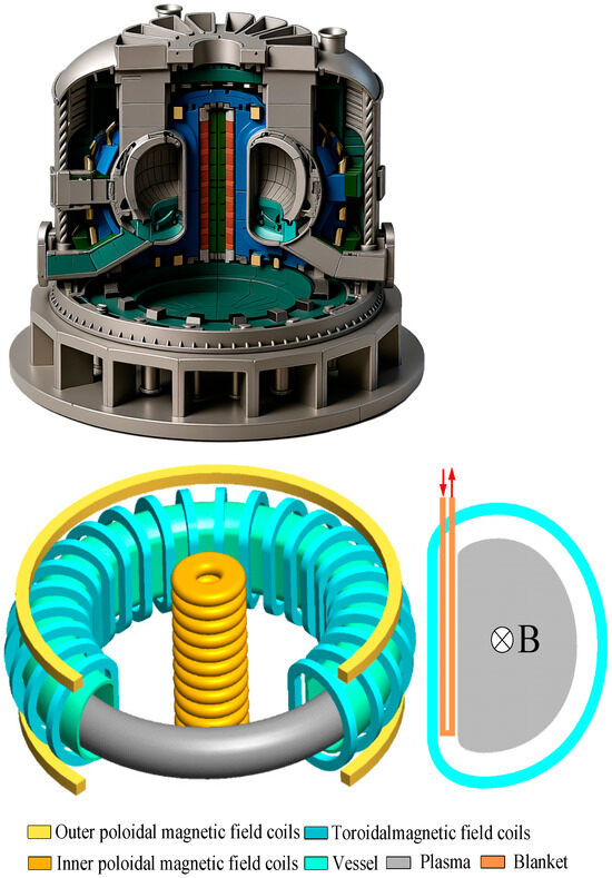
Figure 1.
Schematic diagram of a tokamak device and blanket channel structure.
Wang [9] conducted a numerical investigation of the liquid metal flow and heat transfer process under magnetic field conditions and reported that strong wall-attached jets were generated near the channel walls, entraining the bulk liquid metal flow inside the channel. As the magnetic field strength increased, the magnetohydrodynamic (MHD) Hunt flow effect became more pronounced. Luchinkin [10] simulated the liquid metal flow in the poloidal channels of a tokamak fusion reactor blanket cooling system, obtained temperature fields and heat transfer data through probe measurements, and compared them with numerical simulation results to determine the validity range of the computational model. Zheng [11], taking the Experimental Advanced Superconducting Tokamak (EAST) as the research object, analyzed the deposition distribution and fuel retention on plasma-facing material surfaces along both the poloidal and toroidal directions, revealing in detail the spatial regularities of metallic impurity deposition and deuterium retention characteristics. These findings provided valuable experimental data and insights for understanding plasma–wall interactions and optimizing tokamak operation. Xiang [12] summarized the properties and applications of liquid metal magnetofluids (LMMFs), highlighting their superior heat transfer performance in high magnetic field environments and verifying the effectiveness of utilizing the magnetocaloric effect of liquid metals for thermal management.
To date, most relevant studies have focused on liquid metals as the primary research subject, while systematic investigations specifically targeting tokamak blanket-related parameters remain scarce. The present study aims to address this gap by establishing a mathematical model to comprehensively analyze the thermal–flow characteristics of liquid metal within a tokamak blanket under strong magnetic field conditions. In particular, it explores the influence of background magnetic field strength, blanket channel width, and inlet velocity on the distribution of thermal–flow parameters. The outcomes of this research are expected to provide theoretical guidance for the optimal design and operation of tokamak blankets, as well as offer new perspectives and methodological approaches for related studies, thereby contributing to the advancement of nuclear fusion energy technology.
2. Mathematical Model Development
Liquid lithium–lead (LiPb) alloy, one of the coolants used in dual-cooled lithium–lead blankets, is an incompressible electrically conducting fluid [13,14,15]. In modeling the flow of the metallic fluid inside the blanket, the following basic assumptions are introduced to capture the dominant physical characteristics of the problem:
- The fluid is a Newtonian fluid, and joule dissipation is negligible.
- The fluid has constant physical parameters, including density, thermal volume expansion coefficient, concentration volume expansion coefficient, kinematic viscosity, specific heat capacity, and thermal conductivity.
- Temperature buoyancy and concentration buoyancy are expressed using the Boussinesq approximation [16].
- Since the magnetic Reynolds number Rem << 1, the induced magnetic field is negligible, where Rem = UL/ƞ, U is the characteristic velocity, L is the characteristic length, ƞ = 1/(σµ0) represents the surface magnetic diffusivity, σ is the material conductivity, and µ0 is the vacuum permeability.
- Since this paper focuses on the flow heat transfer process of the liquid metal within the cladding and tritium is a passive transport substance, the tritium content is not considered.
Based on the above assumptions, the governing equations for the flow heat transfer of liquid–liquid lithium-lead within the cladding in a high magnetic environment [17,18,19,20] are obtained as follows:
Continuity equation:
And the Navier–Stokes equation containing the Lorentz force and temperature buoyancy:
The temperature field satisfies the energy conservation equation:
The electromagnetic field satisfies Ohm’s law:
Charge conservation equation:
In the above equations, denotes the velocity vector of the liquid metal, and t is time. p and ρ represent the pressure and fluid density, respectively. , and are the current density, externally applied magnetic field, and electric potential, respectively, while E denotes the electric field strength. is the gravitational acceleration vector. , T, T0, and Q indicate, respectively, the thermal expansion coefficient, fluid temperature, wall temperature, specific heat capacity, and the exponentially distributed volumetric heat source.
In this work, the primary focus is placed on the inner blanket, which is modeled as a rectangular recirculating channel. The background magnetic field is considered spatially uniform, ignoring the self-generated magnetic field during the flow process of the working fluid, and the channel outlet is located adjacent to the volumetric heat source side. The channel length and width are set to l = 0.4 m and m = 0.1 m, respectively. In the experimental configuration, the blanket thickness directly affects the poloidal arrangement number of blanket modules, thus exerting a significant influence on heat transfer performance. For this reason, the blanket thickness is selected as one of the key parameters in the present study. The volumetric heat source Q follows an exponential distribution, with its magnitude given as , the unit of this physical quantity is W/m3. Structured grids are employed for the numerical simulations, with the minimum and maximum grid cell sizes being 0.001 m and 0.002 m, respectively. The computational mesh and boundary conditions are illustrated in Figure 2.
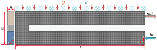
Figure 2.
Study object grid and boundary condition.
3. Results and Discussion
3.1. Influence of Recirculation Channel Design on Heat Transfer and Flow Field Within the Blanket
In practical engineering applications, the common shapes of return flow channels are U-shaped and L-shaped. The L-shaped channel is easier to machine and allows for higher assembly progress during installation, while the U-shaped channel can improve the utilization efficiency of liquid metal. Both structures have their own advantages. To further compare the effects of these two shapes on the thermal flow characteristics within the blankets, this section conducts a comparative analysis of the various physical fields in both U-shaped and L-shaped channels.
Figure 3 shows the electric field distribution on the horizontal mid-plane of channels with different geometries. The results indicate that the electric field in the L-shaped channel exhibits a distribution pattern similar to that of the U-shaped channel. According to Equation (2), it can be inferred that in the L-shaped channel, the Lorentz force generated by the magnetic field on the fluid is relatively weak in the right-angle region. Figure 4 presents the spatial distribution of the volumetric heat source Q for channels with various geometries. It can be observed that the Q distribution depends solely on the channel coordinates and is independent of the specific channel configuration.
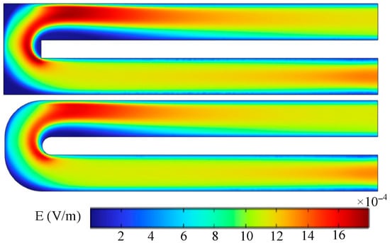
Figure 3.
Electric field distribution for channels with different geometries.
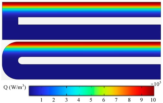
Figure 4.
Volumetric heat source distribution for channels with different geometries.
Figure 5 shows the velocity distribution on the horizontal mid-plane of channels with different geometries. The results indicate that in the L-shaped channel, the high-velocity region near the bend covers a larger area and exhibits greater velocity magnitudes compared with the U-shaped channel. Figure 6 presents the temperature distribution for the two channel configurations. It can be observed that the temperature profiles at the inlet side are similar for both channels, while slight differences appear at the outlet side. In the L-shaped channel, the temperature isotherms in the turning region are shifted closer to the lower wall, which is unfavorable for heat transfer.
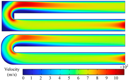
Figure 5.
Velocity distribution in channels with different geometries.
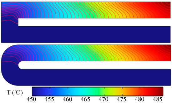
Figure 6.
Temperature distribution in channels with different geometries.
To further examine the thermal–flow characteristics inside the channels, the velocity distributions along the centerline at the inlet and outlet sides were extracted, as shown in Figure 7. When uin = 0.05 m/s, the inlet-center velocity reaches nearly twice the inlet bulk velocity. Combined with the observation from Figure 5, this increase is attributed to the intrinsic flow characteristics, where the boundary layer formed near the channel walls reduces the local fluid velocity, leading to an accelerated core region. At the inlet side, the L-shaped channel exhibits a slightly higher centerline velocity than the U-shaped channel, while at the outlet side, the difference becomes more pronounced: in the turning-centerline region, the L-shaped channel reaches 0.087 m/s, compared with 0.082 m/s for the U-shaped channel—a relative difference of 6%. The outlet flow velocity for both channels is 0.063 m/s. These results imply that the L-shaped channel has a greater flow resistance in the turning section than the U-shaped channel.
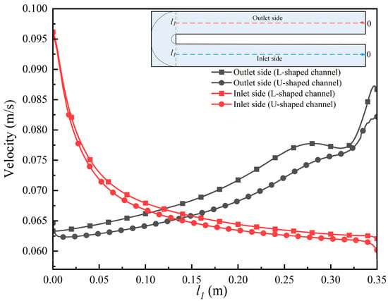
Figure 7.
Velocity variation along the centerline of channels with different geometries.
Figure 8 illustrates the temperature profiles along the centerline of channels with different geometries. When the inlet temperature of the working fluid is 450 °C, the temperature drop between the inlet and outlet is 34.6 °C for the L-shaped channel and 33.2 °C for the U-shaped channel, representing a reduction of approximately 4%. In general, a smaller temperature difference corresponds to lower structural thermal deformation, which is beneficial for the stable operation of the device. Based on the present comparative analysis, the U-shaped channel demonstrates superior thermal performance over the L-shaped channel. Therefore, the subsequent sections will focus on an in-depth investigation of the U-shaped channel configuration.
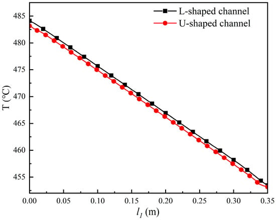
Figure 8.
Temperature variation along the centerline of channels with different geometries.
3.2. Influence of Inlet Flow Velocity on the Thermofluid Characteristics of the Cladding Channel
Figure 9 presents the Lorentz force distribution on the mid-plane of the channel. The results indicate that the Lorentz force component in the z-direction is nearly zero, suggesting that the magnetic field has a negligible effect on the working fluid in this direction. Instead, the electromagnetic influence is primarily manifested in the x- and y-directions, with the magnitude on the outlet side being slightly lower than that on the inlet side. In conjunction with the velocity distribution shown in Figure 10, it can be inferred that this asymmetry in magnetic field effects between the two sides is caused by flow rate variations induced after the fluid undergoes directional changes. Moreover, the larger the initial inlet velocity, the more pronounced this phenomenon becomes.
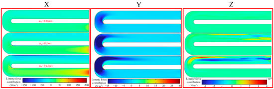
Figure 9.
Distribution of Lorentz force components in the mid-plane of the channel.
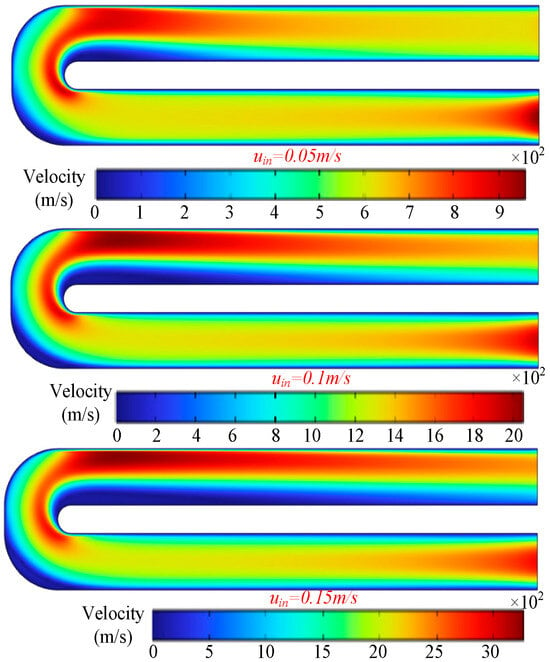
Figure 10.
Velocity distribution in the mid-plane of the channel for different inlet velocities.
Figure 10 shows the velocity distribution on the mid-plane of the channel. The results reveal that, as the inlet velocity increases, the velocity distribution near the outlet becomes less uniform. Specifically, the fluid velocity on the side closer to the heat source increases significantly, whereas the velocity on the opposite side decreases. Figure 11 depicts the temperature distribution on the mid-plane of the channel. The results suggest that increasing the inlet velocity does not substantially alter the overall temperature field pattern within the channel, but it does change the temperature magnitudes. Combined with the observations from Figure 10, it is evident that higher inlet velocities facilitate a reduction in outlet-side temperatures, thereby enhancing the heat transfer efficiency.
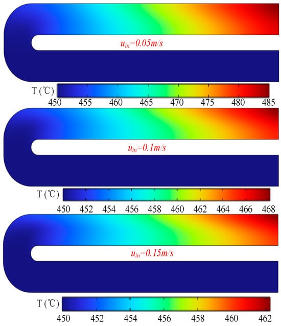
Figure 11.
Temperature distribution in the mid-plane of the channel for different inlet velocities.
Figure 12 presents the velocity profiles extracted along the centerlines on both the inlet and outlet sides of the channel in order to further quantify the aforementioned patterns. The results show that along the flow direction, the fluid velocity on the inlet side initially decreases and then gradually stabilizes, whereas on the outlet side it first decreases rapidly before increasing slowly. In conjunction with the velocity distribution in Figure 10, this behavior can be attributed to the non-uniform velocity distribution between the upper and lower regions after the fluid changes direction, with a clear boundary appearing at the channel centerline. The higher the initial inlet velocity, the more pronounced this boundary becomes, and the greater the velocity difference between inlet and outlet sides. When the initial inlet velocity is 0.05 m/s, the steady-state fluid velocity on the inlet side is approximately 0.06 m/s, representing a 20% increase, and the length of the steady-flow region is about 0.2 m. As the inlet velocity increases, the steady-flow region shortens significantly, whereas the relative increase in the fluid velocity within the steady-flow region, compared to the initial inlet velocity, remains essentially unchanged.
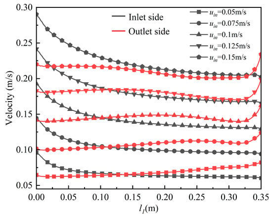
Figure 12.
Velocity profiles along the centerlines of the inlet and outlet sides of the channel.
Figure 13 shows the temperature variation along the channel centerline under different initial inlet velocity conditions. The results indicate that the temperature distribution along the outlet-side centerline exhibits an approximately linear trend. As the initial inlet velocity increases, the temperature drop along the outlet-side centerline becomes more pronounced. Figure 14 presents the centerline temperature at the outlet end face and the corresponding inlet–outlet temperature difference for different initial inlet velocities. The results reveal a nonlinear relationship between the inlet–outlet temperature difference and the initial inlet velocity, with larger inlet velocities leading to smaller temperature differences. A similar trend is observed between the average outlet-end-face temperature and the initial inlet velocity. Under the present operating condition, the inlet fluid temperature is 450 °C. When the initial inlet velocity is 0.05 m/s, the average outlet-end-face temperature is 483.2 °C, while the temperature at the outlet center is 483.3 °C. When the initial inlet velocity is 0.15 m/s, the corresponding temperatures are 460.8 °C and 461.0 °C, respectively. This close agreement indicates that in experimental practice, the outlet temperature can be effectively represented by measuring the temperature at the center of the outlet end face.
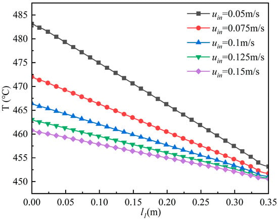
Figure 13.
Temperature profiles along the outlet-side centerline of the channel under different initial inlet velocities.
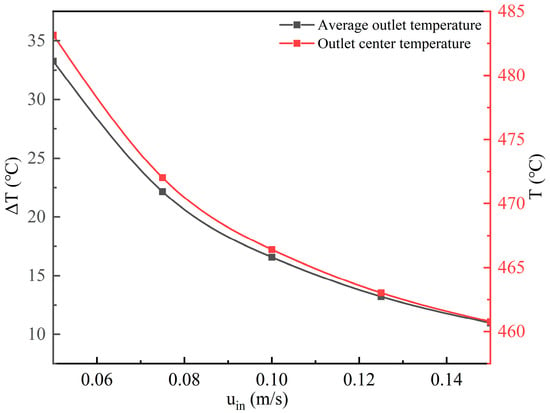
Figure 14.
Center temperature at the outlet end face and inlet–outlet temperature difference under different initial inlet velocities.
3.3. Influence of Background Magnetic Field Intensity on the Thermofluid Characteristics in the Blanket Channel
In practical engineering applications, the background magnetic field serves as an important control parameter. This section investigates the influence of magnetic field intensity on the thermofluid characteristics of the working fluid. Figure 15 illustrates the distribution of Lorentz force components on a selected cross-section within the channel. The results show that increasing the magnetic field intensity has only a negligible effect in the y-direction, with noticeable variations appearing only at the turning regions. In contrast, the effect in the x-direction is significant: as the background magnetic field increases, the Lorentz force acting on the working fluid on the inlet side becomes larger, whereas that on the outlet side decreases.
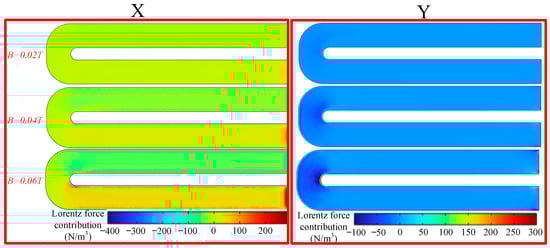
Figure 15.
Lorentz force components on the mid-plane of the channel under different background magnetic field intensities.
Figure 16 presents the velocity distribution on the mid-plane of the channel under different background magnetic field intensities. The results indicate that an increase in magnetic field strength reduces the flow velocity of the working fluid in the channel, resulting in a smaller velocity difference between the outlet side and the inlet side. In conjunction with Figure 15, it can be inferred that a stronger magnetic field imposes a larger Lorentz force on the working fluid at the inlet side, which, in turn, suppresses the local flow velocity. Figure 17 shows the temperature distribution on the mid-plane of the channel under different background magnetic field intensities. The results demonstrate that the magnetic field strength exerts no significant influence on the temperature distribution within the channel.

Figure 16.
Velocity distribution on the mid-plane of the channel under different background magnetic field intensities.
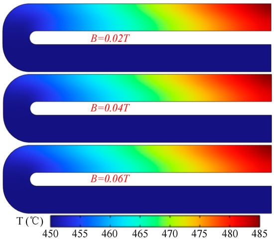
Figure 17.
Temperature distribution on the mid-plane of the channel under different background magnetic field intensities.
Figure 18 illustrates the velocity variation along the channel centerline under different background magnetic field intensities. The results show that on the inlet side, the velocity of the working fluid decreases initially. When the background magnetic field exceeds 0.04 T, a stable-velocity segment is formed within the channel. As the fluid passes through the turning region, the velocity drops sharply again. The length of the stable-velocity segment increases with increasing magnetic field intensity. On the outlet side, the fluid velocity decreases rapidly at the turning position and then increases. When the background magnetic field is greater than 0.04 T, another stable-velocity segment appears before the velocity rises significantly near the outlet. For instance, when the inlet velocity is 0.05 m/s and the magnetic field strength is 0.04 T, the stable-segment velocity is 0.053 m/s; whereas at 0.06 T, the stable-segment velocity is 0.045 m/s, which is close to the inlet velocity. These findings indicate that once the background magnetic field exceeds a certain threshold, it imposes a noticeable restraining effect on the fluid flow within the channel.
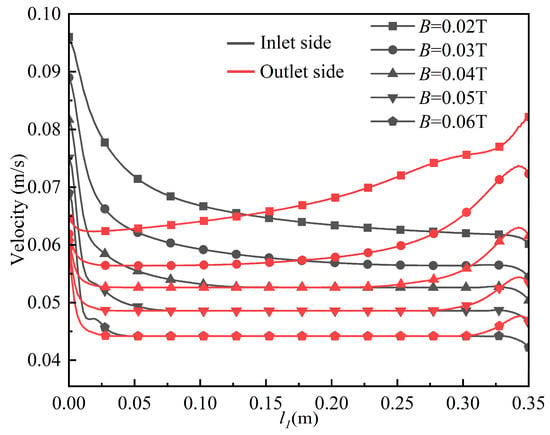
Figure 18.
Velocity profile along the channel centerline under different background magnetic field intensities.
Figure 19 and Figure 20 present, respectively, the temperature variation along the centerline on the outlet side of the channel and the center-point temperature at the outlet end face together with the temperature difference between the outlet and inlet. The results indicate that the background magnetic field strength has no significant effect on the center temperature or on the outlet–inlet temperature difference. As revealed in the preceding analysis, increasing the magnetic field strength reduces the flow velocity of the working fluid, and in Section 3.2 it was shown that a lower flow velocity corresponds to a higher outlet temperature. Combining these observations, it can be concluded that the influence of the magnetic field on the working fluid velocity is limited: it primarily reduces the velocity within the stable region to a value close to the inlet velocity. Consequently, the magnetic field exhibits little impact on the overall temperature distribution of the working fluid.

Figure 19.
Temperature variation along the centerline on the outlet side of the channel.
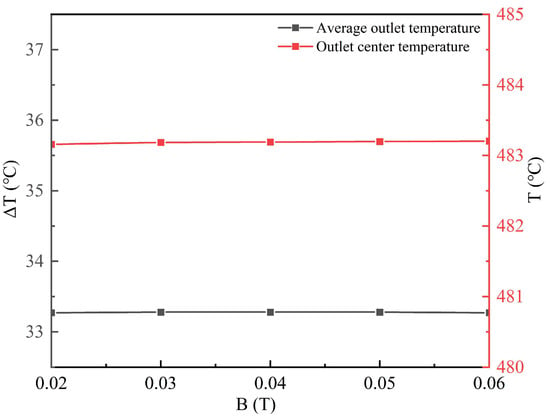
Figure 20.
Center-point temperature at the channel outlet end face and the temperature difference between outlet and inlet.
3.4. Effect of Cladding Thickness on the Thermofluid Characteristics in the Cladding Channel
The cladding thickness has a considerable impact on the mass flow rate of the working fluid. In practical experimental setups, the selection of cladding thickness is also influenced by the segmentation of the cladding and the channel design. In this section, the effect of cladding thickness on the thermofluid characteristics of the working fluid is analyzed.
Figure 21 shows the contribution of the Lorentz force components on the mid-plane of channels with different cladding thicknesses. The results indicate that increasing the cladding thickness leads to a decrease in the Lorentz force contribution along the x-axis. Combined with the analysis in the previous section, it can be seen that under a relatively strong background magnetic field, increasing the cladding thickness can mitigate the magnetic-field-induced flow resistance on the working fluid.
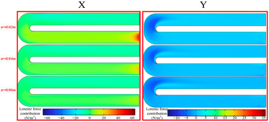
Figure 21.
Lorentz force contributions on the mid-plane of the channel.
Figure 22 presents the velocity distribution on the mid-plane of the channel for different cladding thicknesses. The results indicate that a larger cladding thickness leads to a slight increase in flow velocity near the outlet side, while the velocity of the working fluid near the inlet side decreases. Figure 23 shows the temperature distribution on the mid-plane of the channel. The results demonstrate that cladding thickness has negligible influence on the temperature distribution within the channel. In the experiments, an increase in channel (cladding) thickness led to an increase in the total mass flow rate of the working fluid at the same inlet velocity. In the present numerical results, the computation was terminated when the outlet temperature reached a steady value. Therefore, the temperature distribution is primarily governed by the heat source, whereas the effect of cladding thickness is insignificant.
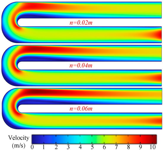
Figure 22.
Velocity distribution on the mid-plane of the channel.
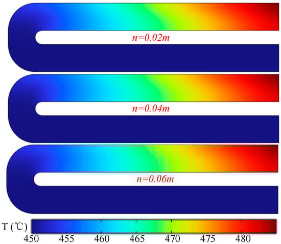
Figure 23.
Temperature distribution on the mid-plane of the channel.
Figure 24 illustrates the velocity variation along the outlet-side centerline of channels with different cladding thicknesses. The results indicate that, as the cladding thickness increases, the centerline velocity near the inlet decreases noticeably. However, after the working fluid flows beyond a certain position, the rate of velocity reduction in the channel with larger cladding thickness becomes significantly lower than that in the thinner-cladding channel. Specifically, when n = 0.02 m, the inlet centerline velocity is 0.096 m/s and the outlet centerline velocity is 0.065 m/s; when n = 0.06 m, the inlet centerline velocity is 0.086 m/s and the outlet centerline velocity is 0.071 m/s. These results suggest that increasing the cladding thickness can suppress the velocity near the inlet region while enhancing the velocity in the vicinity of the outlet.
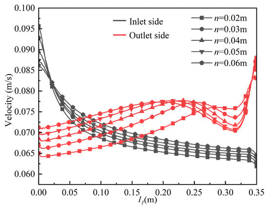
Figure 24.
Velocity variation along the centerline on the outlet side of the channel.
Figure 25 and Figure 26 present, respectively, the temperature variation along the outlet-side centerline of the channel and the centerline outlet temperature together with the temperature difference between the outlet and inlet. The results indicate that the cladding thickness exerts negligible influence on both the centerline outlet temperature and the outlet–inlet temperature difference.
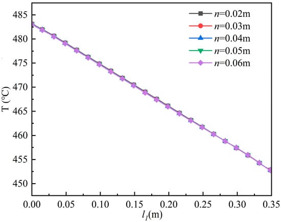
Figure 25.
Temperature variation along the outlet-side centerline of the channel.

Figure 26.
Centerline outlet temperature and temperature difference between outlet and inlet of the channel.
4. Conclusions
In this study, a coupled multi-physics numerical model integrating magnetic field, temperature field, and flow field was developed to systematically investigate the thermal–hydraulic characteristics of the liquid metal breeding blanket for a tokamak device, and the main conclusions are as follows:
- The U-shaped return channel exhibits superior thermal–hydraulic performance compared with the L-shaped channel. Specifically, the flow resistance is reduced by 6%, the outlet–inlet temperature difference decreases by 4%, and the temperature distribution is more uniform, which is beneficial for improving heat-transfer efficiency and reducing the risk of structural thermal deformation.
- Moderately increasing the liquid-metal inlet velocity (0.05–0.15 m/s) can significantly enhance the heat transfer capability. As the inlet velocity increases, the length of the developing section is markedly shortened, whereas the relative improvement in the flow velocity within the fully developed region is less pronounced compared with the increase in inlet velocity.
- Analysis reveals that the magnetic field primarily affects the fluid motion in the x- and y-directions. An increase in the background magnetic-field strength significantly suppresses fluid flow (e.g., when B = 0.06 T, the velocity in the developed section approaches the inlet velocity), while its influence on the temperature field distribution remains minimal.
- Geometric-parameter optimization: Increasing the cladding thickness can effectively mitigate the magnetic-field-induced suppression of fluid flow and improve the velocity distribution in the outlet region. However, its effect on the temperature field is relatively insignificant, providing an important reference for breeding blanket structural design.
Author Contributions
S.C. and J.D.: conceptualization and methodology; S.C. and F.L.: post-processing of numerical calculation results and data extraction; S.C. and J.D.: geometric modeling, analysis of data results, paper writing, results analysis, and calculation result checking. All authors have read and agreed to the published version of the manuscript.
Funding
Project of Science and Technology Tackling Key in Henan Province (242102241062).
Data Availability Statement
All data generated or analysed during this study are included in this published article.
Conflicts of Interest
Author Feng Li is an employee of State Grid Xinyu Electric Power Supply Company. The remaining authors declare that the research was conducted in the absence of any commercial or financial relationships that could be construed as a potential conflict of interest.
References
- Smolentsev, S.; Abdou, M.; Kunugi, T.; Morley, N.; Satake, S.; Ying, A. Modeling of liquid walls in APEX study. Int. J. Appl. Electromagn. Mech. 2001, 13, 373–379. [Google Scholar] [CrossRef]
- Wong, C.P.C.; Abdou, M.; Katoh, Y.; Kurtz, R.J.; Lumsdaine, A.; Marriott, E.; Merrill, B.; Morley, N.; Pint, B.A.; Sawan, M.E.; et al. Progress on DCLL Blanket Concep. Fusion Sci. Technol. 2013, 64, 623–630. [Google Scholar] [CrossRef]
- Wong, C.P.C.; Abdou, M.; Dagher, M.; Katoh, Y.; Kurtz, R.; Malang, S.; Marriott, E.; Merrill, B.; Messadek, K.; Morley, N.; et al. An overview of the US DCLL ITER-TBM program. Fusion Eng. Des. 2010, 85, 1129–1132. [Google Scholar] [CrossRef]
- Wang, T. Superconducting Magnet Technology and Magnetically Confined Fusion. South. Energy Constr. 2022, 9, 108–117. [Google Scholar] [CrossRef]
- Niu, S.J. Nuclear fusion introduction and artificial fusion status. Theor. Nat. Sci. 2023, 28, 10–17. [Google Scholar] [CrossRef]
- Wong, C.P.C.; Malang, S.; Sawan, M.; Dagher, M.; Smolentsev, S.; Merrill, B.; Youssef, M.; Reyes, S.; Sze, D.; Morley, N.; et al. An overview of dual coolant Pb–17Li breeder first wall and blanket concept development for the US ITER-TBM design. Fusion Eng. Des. 2006, 81, 461–467. [Google Scholar] [CrossRef]
- Smolentsev, S. Physical Background, Computations and Practical Issues of the Magnetohydrodynamic Pressure Drop in a Fusion Liquid Metal Blanket. Fluids 2021, 6, 110. [Google Scholar] [CrossRef]
- Litaudon, X.; Bosch, H.-S.; Morisaki, T.; Barbarino, M.; Bock, A.; Belonohy, E.; Brezinsek, S.; Bucalossi, J.; Coda, S.; Daniel, R.; et al. Long plasma duration operation analyses with an international multi-machine (tokamaks and stellarators) database. Nucl. Fusion 2023, 64, 15001. [Google Scholar] [CrossRef]
- Wang, Z.H.; Lei, T.Y. Liquid metal MHD effect and heat transfer research in a rectangular duct with micro-channels under a magnetic field. Int. J. Therm. Sci. 2020, 155, 106411. [Google Scholar] [CrossRef]
- Luchinkin, N.A.; Razuvanov, N.G.; Belyaev, I.A.; Sviridov, V.G. Heat Transfer in Liquid Metal at an Upward Flow in a Pipe in Transverse Magnetic Field. High Temp. 2020, 58, 400–409. [Google Scholar] [CrossRef]
- Zheng, W.; Yan, R.; Ding, R.; Xu, G.; Mu, L.; Zhu, Y.; Liu, Y.; Wan, J.; Chen, J. Post-mortem analysis of material deposition and fuel retention on the plasma-facing materials after the 2021 campaign in EAST. Nucl. Mater. Energy 2024, 41, 101828. [Google Scholar] [CrossRef]
- Xiang, W.; Lu, Y.; Wang, H.; Sun, X.; Chen, S.; He, Z.; Liu, J. Liquid-metal-based magnetic fluids. Nat. Rev. Mater. 2024, 9, 433–449. [Google Scholar] [CrossRef]
- Youchison, D.; Kessel, C.; Nogradi, P. Large Component Simulation of an Inboard Sector of a Dual-Coolant Lead-Lithium Blanket. Fusion Sci. Technol. 2023, 79, 222–250. [Google Scholar] [CrossRef]
- Palermo, I.; Alguacil, J.; Catalán, J.P.; Fernández-Berceruelo, I.; Lion, J.; Valiente, J.Á.N.; Sosa, D.; Rapisarda, D.; Urgorri, F.R.; Warmer, F.; et al. Challenges towards an acceleration in stellarator reactors engineering: The dual coolant lithium–lead breeding blanket helical-axis advanced stellarator case. Energy 2024, 289, 129970. [Google Scholar] [CrossRef]
- Palermo, I.; Warmer, F.; Häußler, A. Nuclear design and assessments of helical-axis advanced stellarator with dual-coolant lithium-lead breeding blanket: Adaptation from DEMO tokamak reactor. Nucl. Fusion 2021, 61, 76019. [Google Scholar] [CrossRef]
- Suarez, D.; Iraola, E.; Serrat, J. Numerical investigation of two-dimensional buoyancy-driven eddies in liquid metal magnetohydrodynamic flows in breeding blankets. Plasma Phys. Control. Fusion 2025, 67, 45019. [Google Scholar] [CrossRef]
- Hinton, F.L.; Waltz, R.E.; Candy, J. Effects of electromagnetic turbulence in the neoclassical Ohm’s law. Phys. Plasmas 2004, 11, 2433–2440. [Google Scholar] [CrossRef]
- Liu, F.B.; Yu, J.; Li, H.B.; Jiang, Z.H.; Geng, X. Numerical Simulation of the Magneto-Hydrodynamic Two-Phase Flow and Heat Transfer during Electroslag Remelting Hollow Ingot Process. Steel Res. Int. 2020, 91, 1900628. [Google Scholar] [CrossRef]
- Peng, Y.; Alsagri, A.S.; Afrand, M.; Moradi, R. A numerical simulation for magnetohydrodynamic nanofluid flow and heat transfer in rotating horizontal annulus with thermal radiation. RSC Adv. 2019, 9, 22185–22197. [Google Scholar] [CrossRef]
- Venkateswarlu, B.; Satya Narayana, P.V.; Joo, S.W.; Metwally, A.S.M. Numerical Simulation of Melting Heat Transfer in Magnetohydrodynamic Fluid Flow over Moving Surfaces: Role of Diffusion and Chemical Reactions. Chem. Eng. Technol. 2025, 48, 12007. [Google Scholar] [CrossRef]
Disclaimer/Publisher’s Note: The statements, opinions and data contained in all publications are solely those of the individual author(s) and contributor(s) and not of MDPI and/or the editor(s). MDPI and/or the editor(s) disclaim responsibility for any injury to people or property resulting from any ideas, methods, instructions or products referred to in the content. |
© 2026 by the authors. Licensee MDPI, Basel, Switzerland. This article is an open access article distributed under the terms and conditions of the Creative Commons Attribution (CC BY) license.