Abstract
We present numerical solutions of the semi-phenomenological model of self-propagating fluid pulses (auto-pulses) in the channel branching into two thinner channels, which simulates branching of a hypothetical artificial artery. The model is based on the lubrication theory coupled with elasticity and has the form of a single nonlinear partial differential equation with respect to the displacement of the elastic wall as a function of the distance along the channel and time. The equation is solved numerically using the 1D integrated radial basis function network method. Using homogeneous boundary conditions on the edges of space domain and continuity condition at the branching point, we obtained and analyzed solutions in the form of auto-pulses penetrating through the branching point from the thick channel into the thin channels. We evaluated magnitudes of the phenomenological coefficients responsible for the active motion of the walls in the model.
1. Introduction
The arterial systems are characterised by branching with a network of larger arteries splitting into smaller arteries which continue to bifurcate into arterioles and then into the capillaries. Therefore, in this paper we focus on simulation of pulses in branching channels. In our recent work [1] only non-branching (single) channels were considered; this is the major difference between the two studies. In addition, in the present paper we evaluate the empirical coefficients playing the key role in our model.
We emphasize that the model simulates an artificial, not a real, artery. Note that the recent years saw a remarkable progress in design and fabrication of artificial muscles. For example, Reference [2] describes the fluid-driven and origami-inspired artificial muscles.
Arterial blood flows are usually modelled by the classical Navier-Stokes equations. However, under certain conditions, non-Newtonian models are also used [3,4,5]. While some models consider arteries with rigid walls [6], most models assume the walls to be elastic [7]. Roberts [8] presented a simple argument why the elasticity of an artery is important: if arteries were not elastic then each pump of the heart would cause an immediate rise in blood pressure throughout the body.
Our analysis is based on the model [9], which further developed the ideas of Roberts of channels with active walls [8]. While Roberts considered the case of negligible viscous forces compared to inertia, which is relevant to wider channels, we will consider the case when inertia is negligible compared to viscous forces, which is relevant to narrow channels. In the previous paper of the current authors [1], a variety of pulse solutions is obtained for a single channel. In the current paper we consider branching channels and analyse the conditions under which a pulse can successfully propagate from a thick channel into a thin one through the branching point. Ultimately we aim to make our model self-consistent that is to have characteristics that gurantee the propagation of the pulses over the entire system of branching channels.
Strunin [9] considered the flow between infinite elastic walls, assuming symmetry with respect to the plane, ; hence it will suffice to analyse only half of the flow, , (see Figure 1). The mean flow is assumed to be in the x-direction, driven by the pressure gradient in that direction. Adopting the lubrication theory for the flow [10] we equate the pressure gradient to the viscous friction.
where is the flow velocity in the x direction, is the pressure and the viscosity.
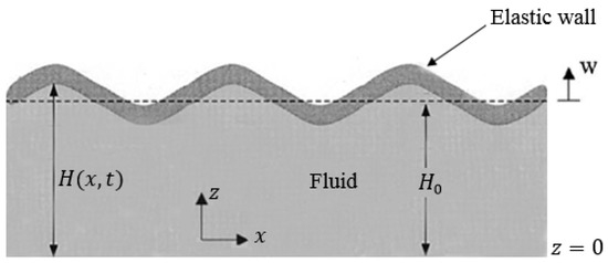
Figure 1.
Fluid flow between elastic walls (half of the channel is shown).
The mass flux Q is
Define the displacement, , of the wall in the z direction from the neutral position, , by
Then the continuity equation becomes
As we can see, the Equation (6) links the displacement of the flow boundary, coinciding with the wall position, to the flow pressure. The elasticity theory [11,12] provides the reverse link from the pressure to the displacement
where
In (7) and (8) is the wall’s displacement along the flow, D is the flexural rigidity of the wall, E is Young’s modulus, h is the thickness of the wall, is Poisson’s ratio and N the force caused by the displacements. Strunin [9] supposed that the walls exert extra pressure relative to (7),
where depends on w. He postulated that is proportional to the 4th power of the vertical displacement,
After further simplifying assumptions (for more details see Reference [9]), the model has the form
Dynamically the term has dissipative effect, the nonlinear term, , represents excitation and the nonlinear term transfers the energy from the excitation to dissipation.
Now we non-dimensionalize Equation (12) using some relevant scales to the form
where the coefficients A, B and C are non-dimensional.
2. Numerical Experiments
To solve Equation (13) numerically we used the one-dimensional integration radial basis function network (1D-IRBFN) method in conjunction with one-step Picard iteration (PI1) scheme [13]. This method is more efficient than the original IRBFN method presented by Mai-Duy and Tran-Cong [14]. The purpose of using integration instead of conventional differeniation to construct the Radial Basis Function (RBF) approximations is to improve the stability and accuracy of the numerical solution. In the present paper, we use the following notations: for a vector/matrix that is associated with a grid line and to denote selected components of the vector . In this method, the highest-order derivative, 6th order, is approximated by radial basis functions. The lower-order derivatives and function itself are then obtained by integration.
where x is the input vector, N is the number of nodes on the x-axis, are RBF weights to be determined; are known RBFs, for example, for the case of multiquadrics (MQ)
where and are the centre and width of the MQ-RBF, respectively. The set of centres is chosen to be the same as the set of collocation points and the RBF width is determined as , is a factor (presently ) and is the distance from the i-th centre to the nearest; ; ; ; ; ; ; the set of constants arising from the integration process. The new basis functions , , , and are obtained from integrating the multiquadrics as follows,
where . After discretization, Equations (14)–(20) can be written in a compact form as
where
…,
where is the set of nodal points, , , and . We denote . Equation (13) is discretized with respect to both time and space variables. Firstly, the time interval is partitioned into N subintervals of length with and . The temporal discretization is then accomplished by a time-stepping scheme, followed by the spatial discretization based on the IRBFN method. Among the many possible time-stepping schemes, the standard -scheme [15], is used in this work. The extreme cases and correspond to the well-known forward (fully explicit) and backward (fully implicit) Euler schemes, respectively. The scheme with is known as the (semi-implicit) Crank-Nicolson method which is second-order accurate. We re-write Equation (13) as
where
Applying the standard -scheme with Equation (22) is discretized as
where is the physical time step; and the superscripts and denote the previous and current physical time levels, respectively. Note that in Equation (24) consists of nonlinear terms. The one-step Picard iteration uses the solution at the previous time level to linearize the nonlinear terms. Equation (24) becomes
For simplicity, the above equation can be written as,
and the boundary conditions as
The system of Equations (27) and (28) is solved simultaneously at each time step for until the prescribed time T is reached. Numerical experiments are conducted on a computer with an Intel i7, 3.60 GHz processor and 16 GB RAM using Matlab-R2017b software. The following subsections present the numerical results.
2.1. Two-Channel Experiment
In this numerical experiment we consider a thick channel branching into two thin channels as shown in Figure 2. In the state of rest each of the thin channels has half the width of the thick channel.
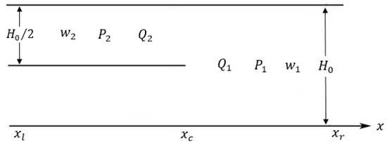
Figure 2.
Branching channels (in the state of rest).
The displacement of the channel walls satisfy the equations
where we assume that the parameters (and ) may be different between the channels. The boundary conditions are chosen homogeneous, namely zero values of the function and its first two derivatives at the edges, (l stands for “left”) and (r stands for “right” ),
In the experiments we used and (see Figure 3, Figure 4, Figure 5, Figure 6, Figure 7, Figure 8, Figure 9 and Figure 10). For the branching (contact) point the following boundary conditions are set. The kinematic condition expresses continuity of the wall displacement,
where c stands for “contact”, see Figure 2. The next conditions ensure continuity of the pressure (see (7)),
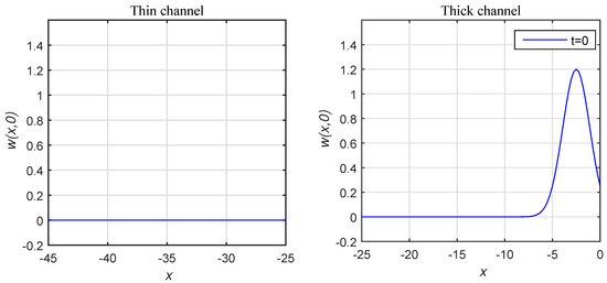
Figure 3.
The initial condition initiating the pulse in the thick channel.
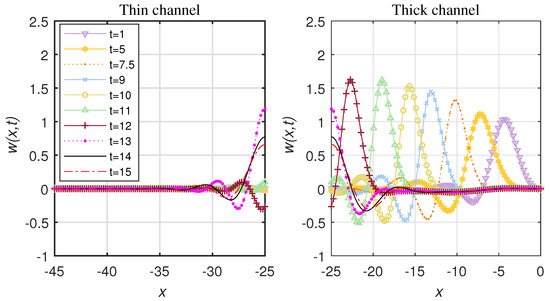
Figure 4.
The solution from to .
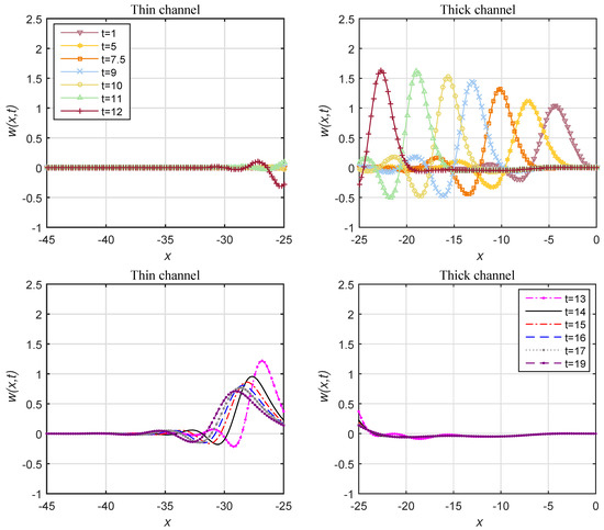
Figure 5.
Pulse propagation through the contact point showing the (top) early and (bottom) late stages ().
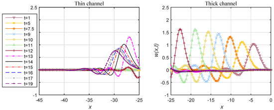
Figure 6.
The experiment with (); the time ranges from to 19.
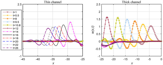
Figure 7.
The experiment with (); the time ranges from to 26.
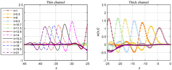
Figure 8.
The experiment with (); the time ranges from to 21.
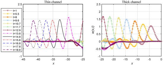
Figure 9.
The experiment with (); the time ranges from to .
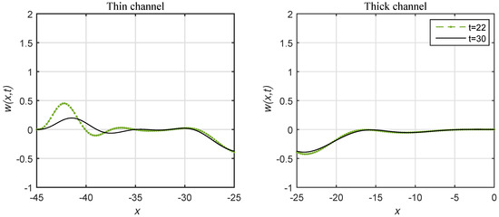
Figure 10.
Continuation from Figure 9. .
We used (see Figure 3, Figure 4, Figure 5, Figure 6, Figure 7, Figure 8, Figure 9 and Figure 10). The last condition will ensure continuity of the mass flux. According to (3), the flux for the thick channel is
As the width of the thin channel is , from Equation (33) the mass flux for the thin channel is
The continuity of the flux requires
Assuming continuity of the velocity in (36) we have
Prior to the numerical experiment we non-dimensionalized all the equations (see Section 3 for details) and the values of A, B and C were chosen such that , and . The size of spatial domain in each numerical experiment is chosen such that: (1) the experiment does not last too long before a settled stage is reached and (2) the pulses are satisfactoryly resolved in space. The number of nodes is 100, the time step and the size of the domain . In the first experiment, we assumed that and . After non-dimensionalizing the thick channel equation to the form
the non-dimensional thin channel equation becomes
where . We set the initial condition in the thick channel as and in the thin channel as shown in Figure 3.
From Figure 4, we see that in this particular experiment the pulse in the thick channel is not propagating to the thin channel. In the second experiment, in an attempt to make the pulse propagate into the thin channel we increased the value of (the thin channel parameter) by the factor of eight
As a result, we observed the dynamics shown in Figure 5. The pulse propagates from the right end of the thick channel towards its left end as time goes. The evolution of the pulse starts from a single hump in the thick channel. After a while, the solution takes a familiar pulse-like form moving towards the contact point. The homogeneous boundary conditions were used at the left end of the thin channel and right end of the thick channel. At , the pulse reaches the contact point .
Despite the pulse does make it into the thin channel and spends some time propagating through it, its height rapidly decreases and the pulse eventually decays without reaching the end of the channel. Looking at the mathematical structure of the governing equations, the only difference is the factor 1/8 in the right-hand side of the thin-channel equation compared to the thick-channel equation. Hence, the pulse solution definitely exists for the thin channel. But, as opposed to the way the pulse is started in the thick channel, within the thin channel we do not have freedom to choose the way the pulse is started, because it is already shaped by previous dynamics. In order to support the propagation in the thin channel we decided to increase the excitation coefficient in the thin channel, so that the thin channel non-dimensional parameters (Figure 6). An interesting question is what is the minimum (critical) value of b in the thin channel to guarantee the pulse survival. We increased the excitation coefficient b in the thin channel from experiment to experiment by increments (Figure 6, Figure 7, Figure 8 and Figure 9) until the pulse survived. Observe from Figure 6 that at a relatively low excitation level in the thin channel the pulse only travels to the mark of just over 30. At a higher excitation rate, as illustrated in Figure 7, the pulse travels further, namely to the mark of over 35. For an even higher excitation, see Figure 9, the pulse manages to propagate through the entire length of the thin channel.
The pulse finally disappears after hitting the left boundary of the thin channel as shown in Figure 10.
We determined that the critical value of the excitation coefficient in the thin channel is approximately .
2.2. Three-Channel Experiment
In this numerical experiment, we consider a three-channel configuration where a thick channel branches out into two thin channels and each of them in turn branches out into two even thinner channels. In the state of rest each of the thinner channels has half the width of the thicker channel with which it is in contact. The boundary conditions and the initial condition are the same as in the previous experiment. The displacement of the thinnest channel wall, , satisfies the equation
Now we non-dimensionalize Equation (44) to the form
where the non-dimensional coefficient . We run the numerical experiments in the similar fashion to the two-channel experiments, until the pulse survived in the thinnest channel as shown in Figure 11.
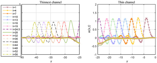
Figure 11.
The experiment with ; the time ranges from to 56.
Figure 12 shows that the pulse decays after hitting the left boundary of the thinnest channel.
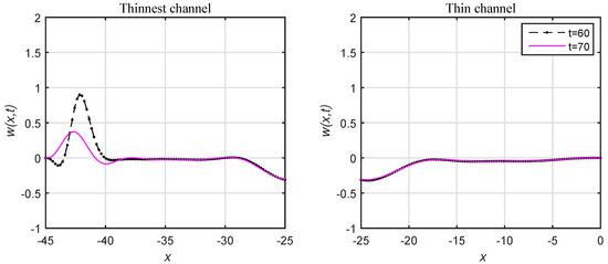
Figure 12.
Continuation from Figure 11. .
We then determined that the critical value of the non-dimensional excitation coefficient in the thinnest channel is approximately .
3. Evaluation of the Model Coefficients
In this section, we evaluate the coefficients and , which were introduced in the original model [9] empirically. The idea is to select and in such a way that the dimensional amplitude and dimensional velocity of the pulse have realistic values, that are values typical for a human artery (by the order of magnitude). Let us re-scale the main dimensional Equation (12) in two steps. In step one, we non-dimensionalize the equation using as the spatial scale and as the time scale. Then, in step two, we re-scale w, t and x using the yet-to-be-determined non-dimensional scaling factors W, T and X, respectively. Thus,
The resulting non-dimensional equation is
where
In the numerical experiments we used
Using the settled single-pulse solution in say the thinnest channel (before the pulse hit the boundary), we can measure the non-dimensional amplitude of the pulse and the non-dimensional pulse speed . Returning to the dimensional quantities, we have, for the dimensional pulse amplitude,
and, for the dimensional pulse speed,
We require that the coefficients and lead to realistic orders of magnitude for and v in (49) and (50). Of course we remember that our hypothetical channels do not have realistic cylindrical shape but the methodology of evaluation of and is applicable to any version of the model including possible future versions with cylindrical configuration. From the literature, by the order of magnitude, [16,17] and . The three Equations (48) (where A, B and C are given by (47)) and Equations (49) and (50) form a system of five equations with respect to the five parameters W, X, T, and that are to be determined. We find
As we noted, and are measured from the numerical experiments (Figure 11): and approximately. The other parameters have the following approximate values: , the Young’s modulus [18], the Poisson ratio [19,20,21,22,23,24], the blood viscosity [22] and the wall thickness [24]. Therefore, the flexural rigidity . Based on these figures, we have, by the order of magnitude,
and
4. Conclusions
We applied the 1D-IRBF numerical method to solve the model of the flow between active walls adapted for a branching channel. We used homogeneous boundary conditions at the edges and continuity conditions at the branching (contact) point. We obtained and analyzed solutions in the form of auto-pulses penetrating through the branching point from the thick channel into the thin channel. The numerical experiments showed that the pulse decays while moving through the thin channel unless the excitation coefficient in the thin channel is increased. Therefore, we conducted a series of experiments using larger values of the excitation coefficient in the thin channel until the pulse “survived.” The numerical results indicated that the thinner the channel the larger the excitation coefficient needs to be in order to guarantee the pulse propagation. Based on the numerical experiments, we evaluated the empirical parameters and responsible for the active component of the wall dynamics. So far we explored the branching configuration with only two branching points as maximum. In the future, it would be interesting to study a system of multiple vessels with three or more branching points.
Author Contributions
Conceptualization, D.S.; Formal analysis, F.A.; Investigation, D.S. and F.A.; Methodology, D.S.; Visualization, F.A.; Writing—original draft, F.A.; Writing—review and editing, D.S.
Funding
This research received no external funding.
Conflicts of Interest
The authors declare no conflicts of interest.
References
- Ahmed, F.Z.; Mohammed, M.G.; Strunin, D.V.; Ngo-Cong, D. Simulations of autonomous fluid pulses between active elastic walls using the 1D-IRBFN method. Math. Model. Nat. Phenom. 2018, 13, 47. [Google Scholar] [CrossRef]
- Li, S.; Vogt, D.M.; Rus, D.; Wood, R.J. Fluid-driven origami-inspired artificial muscles. Proc. Natl. Acad. Sci. USA 2017, 114, 13132–13137. [Google Scholar] [CrossRef] [PubMed]
- Bessonov, N.; Sequeira, A.; Simakov, S.; Vassilevskii, Y.; Volpert, V. Methods of blood flow modelling. Math. Model. Nat. Phenom. 2016, 11, 1–25. [Google Scholar] [CrossRef]
- Robertson, A.M.; Sequeira, A.; Owens, R.G. Rheological models for blood. In Cardiovascular Mathematics; Springer: Milano, Italy, 2009; pp. 211–241. [Google Scholar]
- Robertson, A.M.; Sequeira, A.; Kameneva, M.V. Hemorheology. In Hemodynamical Flows; Birkhäuser: Basel, Switzerland, 2008; pp. 63–120. [Google Scholar]
- Quarteroni, A.; Veneziani, A.; Zunino, P. Mathematical and numerical modeling of solute dynamics in blood flow and arterial walls. SIAM J. Numer. Anal. 2002, 39, 1488–1511. [Google Scholar] [CrossRef]
- Alastruey, J.A. Numerical Modelling of Pulse Wave Propagation in the Cardiovascular System: Development, Validation and Clinical Applications. Ph.D. Thesis, University of London, London, UK, 2006. [Google Scholar]
- Roberts, A.J. A One-Dimensional Introduction to Continuum Mechanics; World Scientific: Singapore, 1994. [Google Scholar]
- Strunin, D.V. Fluid flow between active elastic plates. ANZIAM J. 2009, 50, 871–883. [Google Scholar] [CrossRef][Green Version]
- Huang, R.; Suo, Z. Wrinkling of a compressed elastic film on a viscous layer. J. Appl. Phys. 2002, 91, 1135–1142. [Google Scholar] [CrossRef]
- Landau, L.D.; Lifshitz, E.M. Theory of Elasticity; Pergamon: London, UK, 1959; pp. 57–60. [Google Scholar]
- Timoshenko, S.; Woinowsky-Krieger, S. Theory of Plates and Shells; McGraw-Hill: New York, NY, USA, 1987. [Google Scholar]
- Ahmed, F.Z.; Strunin, D.V.; Mohammed, M.G.; Bhanot, R.P. Numerical solution for the fluid flow between active elastic walls. ANZIAM J. 2016, 57, 221–234. [Google Scholar] [CrossRef]
- Mai-Duy, N.; Tran-Cong, T. Numerical solution of differential equations using multiquadric radial basis function networks. Neural Netw. 2001, 14, 185–199. [Google Scholar] [CrossRef]
- Quarteroni, A.; Valli, A. Numerical Approximation of Partial Differential Equations; Springer: New York, NY, USA, 1997. [Google Scholar]
- London, G.M.; Pannier, B. Arterial functions: how to interpret the complex physiology. Nephrol. Dial. Transpl. 2010, 25, 3815–3823. [Google Scholar] [CrossRef] [PubMed]
- Lehmann, E.D. Clinical value of aortic pulse-wave velocity measurement. Lancet 1999, 354, 528–529. [Google Scholar] [CrossRef]
- Zhang, X.; Kinnick, R.R.; Fatemi, M.; Greenleaf, J.F. Noninvasive method for estimation of complex elastic modulus of arterial vessels. IEEE Trans. Ultrason. Ferroelectr. Freq. Control 2005, 52, 642–652. [Google Scholar] [CrossRef] [PubMed]
- Olufsen, M.S.; Peskin, C.S.; Kim, W.Y.; Pedersen, E.M.; Nadim, A.; Larsen, J. Numerical simulation and experimental validation of blood flow in arteries with structured-tree outflow conditions. Ann. Biomed. Eng. 2000, 28, 1281–1299. [Google Scholar] [CrossRef] [PubMed]
- Matthys, K.S.; Alastruey, J.; Peiró, J.; Khir, A.W.; Segers, P.; Verdonck, P.R.; Parker, K.H.; Sherwin, S.J. Pulse wave propagation in a model human arterial network: assessment of 1-D numerical simulations against in vitro measurements. J. Biomech. 2007, 40, 3476–3486. [Google Scholar] [CrossRef] [PubMed]
- Surovtsova, I. Effects of compliance mismatch on blood flow in an artery with endovascular prosthesis. J. Biomech. 2005, 38, 2078–2086. [Google Scholar] [CrossRef] [PubMed]
- Avolio, A.P. Multi-branched model of the human arterial system. Med Biol. Eng. Comput. 1980, 18, 709–718. [Google Scholar] [CrossRef] [PubMed]
- Kalita, P. Shell Models of the Artery Wall. Schedae Inform. 2004, 13, 104–122. [Google Scholar]
- Quarteroni, A.; Tuveri, M.; Veneziani, A. Computational vascular fluid dynamics: problems, models and methods. Comput. Vis. Sci. 2000, 2, 163–197. [Google Scholar] [CrossRef]
© 2019 by the authors. Licensee MDPI, Basel, Switzerland. This article is an open access article distributed under the terms and conditions of the Creative Commons Attribution (CC BY) license (http://creativecommons.org/licenses/by/4.0/).
