Abstract
The scour process of sand particles and multi-grain size and density particles were studied to investigate the segregation process of different particles in a confined channel. The effects of jet intensity and submergence as two controlling parameters were studied, and scour characteristics and profiles were measured. The time history of the scouring process was measured and the results were compared with the scour process in a uniform sand bed as benchmark tests. Experimental data revealed that the eroded area of different particle types increased with the jet intensity, but the erosion of relatively heavier particles was limited due to jet diffusion. The local erosion was affected by the level of submergence and more erosion occurred near the nozzle at low submergence. Increasing the jet Froude number increased the area of deposition, while submergence reduced the overall area of deposition. As submergence increased from 4 to 12, the area of sand particles reduced by more than 50% while the jet intensity was constant. In shallow submergence, increasing jet intensity from 1.46 to 2.11 increased the area of lead balls by 120%, whereas in relatively deep submergence, incrementing jet intensity increased the area of lead balls by more than five times. The effect of flow intensity on variations of scour dimensions was quantified by the densimetric Froude number. While a densimetric Froude number based on mean particle size, D50, was found to be suitable to estimate maximum scour bed in uniform sand beds, experimental data indicated that the best fit is achievable to predict maximum scour depth in multi-grain size and density once D95 is used. Semi-empirical models were proposed to predict scour dimensions as a function of the densimetric Froude number.
1. Introduction
Studying the effects of bed material and hydraulic conditions on the geometric characteristics of scour and deposition such as depth, width, and length downstream of hydraulic structures such as, spillways, gates, weirs, and jets is of utmost importance from the engineering point of view [1,2,3,4,5,6]. The scouring induced by a water jet constantly impinging on an erodible bed is important and it is present in natural and practical applications [7]. Many laboratory experiments have been carried out to investigate the evolution of scour downstream of two-dimensional (2D) plane and three-dimensional (3D) circular wall jets [8,9,10,11,12,13,14,15,16,17,18,19,20,21,22]. Recent research studies emphasised the importance of controlling parameters in scour formation and the corresponding difficulties in estimation of local scour induced by turbulent wall jets [23,24,25,26]. The development of slurry jets and particle clouds under different hydraulic conditions helps to understand the momentum and energy transfer from sediments to the ambient water, and this information can be utilized to estimate the sediment power, which is the primary cause of local erosion [27,28,29].
Dimensional analysis has been one of the main methods in prediction of the characteristic length scales in local scour induced by turbulent wall jets [13]. Many studies employed dimensional analysis to correlate the controlling parameters with the characteristics of scour and analyze scour development [7,14,15]. The main geometric characteristics of scour are scour depth, length, and width, and the hydraulic parameters that affect the mentioned characteristics downstream of hydraulic structures are the downstream Froude number and submergence ratio [14,21,30]. Aamir and Ahmad [17] reported that the interaction between the jet’s hydrodynamics and bed materials is the key phenomenon in estimating scour evolution. Recent investigations have attempted to develop different models to predict scour induced by turbulent wall jets [23,24,25]. The key parameters in flow classification are the jet’s geometry, which classified as two- or three-dimensional [30,31,32], the submergence condition, which can be divided into submerged and unsubmerged conditions depending on the tailwater depth [30], and the jet intensity, which can be quantified by the densimetric Froude number of the jet [10,14,33,34].
The effects of particle size and its interaction with other particles can significantly change the size and development of local scour induced by submerged wall jets [10]. The effect of sediment gradation on scour size was studied by Aderibigde and Rajaratnam [13]. A representative particle size of D95, defined as a grain size for which 95% of material is finer, was introduced for sediment mixtures. A linear correlation was proposed between scour depth, jet scaling parameter, normalized particle size, and densimetric Froude number, which is defined as FD = uo/(gD50Δρ/ρw)1/2, where uo is the initial jet velocity, D50 is the mean bed particle diameter, g is the gravitational acceleration, Δρ is the density difference between the bed material and water, and ρw is the density of water. The densimetric Froude number defines a relationship between the tractive and resistive forces on a single particle [10]. In the case of a sediment bed with a wide range of particle sizes, smaller particles are lifted from the bed and carried away by the mean flow. While large particles remain due to higher resistive force. Sediment segregation occurs over time because of wide sediment size distribution [30].
The effects of controlling parameters such as jet intensity have been tested in the literature [23,24,25,26,35], but fewer attempts have been made to investigate the effects of jet intensity and submergence on multi-particle size and density beds. The composition of bed material in the field is not uniform and the proposed models for prediction of scour on uniform sand bed results in significant error when it is employed for multi-grain size beds in real scenarios. Due to the armoring effect, the scour dimensions in multi-size and density beds are significantly different from scour induced by turbulent jets on uniform non-cohesive beds [21]. Therefore, the present study attempts to fill the knowledge gap in prediction of scour dimensions in multi-grain size and density beds. Accordingly, a series of experimental study was carried out to study the particle separation and armoring effect on a mixture of multi-density and multi-size particles induced by turbulent wall jets in a submerged flow condition.
The mixture of bed particles in the proposed study has different sizes and densities and was selected to study the separation of heavy minerals from mining ore as an example of a multi-size and density bed. The controlled application of a circular wall jet helps the separation of heavy particles from sand particles that can be utilized for optimization of mineral separation during preliminary extraction processes. The characteristic dimensions of the scour, such as scour depth, width, and length, in multi-density particles were measured and the results were compared, with the benchmark tests consisting of sediment erosion of uniform sand particles. The main goal of the proposed study is to investigate the effect of submergence by changing the tailwater depth and flow intensity by varying the densimetric Froude number on scour characteristics of multi-density and uniform-density loose beds.
The effects of hydrodynamic parameters such densimetric Froude number and jet scaling factors were investigated for different jet intensities and different levels of submergence. Empirical models were formulated based on dimensional analysis and equations were proposed for prediction of scour dimensions in both uniform sand and multi-density beds. The present study aims to investigate the effect of the initial hydrodynamic parameters on the local erosion of a loose bed by circular turbulent wall jets with different submergence levels in clear water condition. The obtained results and proposed models advance knowledge beyond previous studies.
2. Experimental Setup
A series of laboratory experiments was carried out in a glass-walled tank of 2.0 m length, 0.46 m width, and 0.48 m height in the Multiphase Flow Research Laboratory (MFRL) at Lakehead University, Canada. The experimental setup consists of a sediment bed section 1.0 m long, 0.14 m deep and with the same width as the tank, installed inside the tank. A circular wall jet was generated by discharging water through a nozzle with a nozzle diameter of do = 0.0127 and 0.0254 m and different discharges ranging between Q = 22.2 L/min and 32.1 L/min. The sediment section was leveled to the invert of the nozzle outlet to form a wall jet with no offset. A schematic diagram of the experimental setup and the adopted coordinate system is shown in Figure 1. The submergence is defined as a ratio of the water depth above the bed, Yt, to the nozzle diameter, do. The water temperature was kept constant at 20 ± 1 °C for all experiments. A sharp-crested weir with variable heights was placed at the downstream section to control the water level, Yt, in the sediment test section. Four tailwater depths were adjusted to provide a relatively wide range of submergence, Yt/do = 2, 4, 6, and 12.
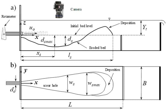
Figure 1.
Schematics of the experimental setup and coordinate system: (a) side view; (b) top view.
A uniform sand bed section was constructed by sand particles with a mean diameter of D50 = 0.38 mm. The obtained results from the sand bed section were utilized as a benchmark to study the effect of bed armoring and particle segregation on scour development. To study the segregation of mining ore due to scour formation and armoring effect downstream of a three-dimensional circular wall jet, a bed mixture consisting of four different particles representing a mixture of a specific mining ore in northern Ontario was used. The characteristics of the multi-density and multi-size bed and the uniform sand section are summarized in Table 1. The jet flow was generated by a submergible pump. To avoid transmitting any vibrations from the pump to the test section and reduce measurement uncertainties, the pump was placed 5 m away from the tank. The jet discharge, Q, was controlled by a valve, and discharge was measured by an accurate rotameter (FCH-C-PA, 97478431, BioTech e.k, Vilshofen, Germany). The photos of the experiment setup in the hydraulic lab and the top view image of a sample scour of the multi-density bed are shown in Figure 2.

Table 1.
Particle size and size distributions of the uniform and mixed bed material used in this study.
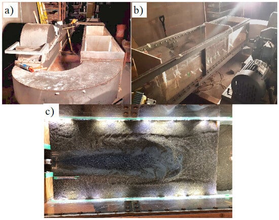
Figure 2.
Images of experimental setup and test section in the hydraulic lab: (a) frontal view; (b) side view; (c) top view.
Sieve analysis was performed to assess particle size distribution and the characteristic S curve for each material was obtained. The density of each particle in the mixed bed was measured using the suspended particle method to separate particles according to their density. The Reynolds number of the jet was determined as Re = uodo/ν, where uo is the initial jet velocity (i.e., uo = Q/(πdo2/4)) and ν is the kinematic viscosity of water at 20 °C. The jet Froude number was determined as Fr = uo/(gdo)1/2 and it varied from 1.46 to 11.96. The experiments were labeled based on the combination of the bed material and controlling parameters. The first letter denotes the type of bed material, where U stands for uniform and M stands for mixed bed. The first number in each test is the nominal discharge in L/min followed by submergence, Yt/do. For example, the test (U-22-8) performed over a uniform bed with an approximate discharge of 22 L/min and submergence ratio of, Yt/do = 8. A total of 60 experiments were performed to study the local scour development in both uniform and multi-density beds (see Table 2).
Table 2.
Experimental variables and non-dimensional parameters in the present experimental study.
To achieve the equilibrium state, the geometries of scour hole downstream of submerged turbulent wall jets were measured over time and the experiments were terminated once the scour geometries became constant within a 30 min period. Great care was taken to monitor the local motions of particles to select the last 30 min time interval to justify termination of experiments. The selected method to determine equilibrium state resulted in an overall experimental time of 8 h for each run. The scour depth, ds, maximum scour length, ls, width, ws, and the distance from the nozzle to the deepest scour, xs, were measured at each time interval. The longitudinal profile of scour was measured at 0.1 m distance intervals using a point gauge with an accuracy of ±0.1 mm. The water within the test section was drained at each time step and water was carefully refilled to reach the desired tailwater level.
A high-resolution camera (Photron Fastcam, 1024PCI100KC, Tokyo, Japan) was placed above the tank to capture images of scour development over time. Due to rapid variations of scour geometry over time, the top view images were captured with a time interval of 2 min in the first 30 min of the experiment. The time interval of images increased to 5 min for the second 30 min. After one hour from the beginning of the test, the time interval of imaging increased to 10 min. Three hours from the commencement of each test, the images were captured every 30 min and the time interval increased to one hour till the end of the experiment. LED strip lights (Zorsen Led 5050, Ansen, Shenzhen, China) were placed around the tank to improve the quality of images and to set suitable contrast between each type of particle. An image processing toolbox in the MATLAB (2018) [36] software package (MatWorks, 2018. version 9.7.0, Natick, MA, USA) was employed to extract the boundaries of different particles and to capture the maximum scour length, ls, and width, ws, using an in-house code. The edges of the scour were captured using the in-house MATLAB program.
3. Results
3.1. Visualization
The present study shows the effect of bed configuration on local erosion results of loose beds induced by 3D circular turbulent wall jets with different tailwater depth in clear water condition. The prediction of the characteristic dimensions of the scour hole will help to avoid possible failure in hydraulic structures. Moreover, the full understanding of this phenomenon could be employed in mining operations to separate heavy particles from a multi-density mixture in an extraction process. Furthermore, the effect of the mentioned parameters is considered to compare the results with those reported in the literature.
Figure 3 shows the impact of tailwater and flow intensity on local scour characteristics of uniform sand beds in a confined channel. The top view of the scour profiles, produced by 3D circular horizontal jets, shows an irregular semi-elliptical scour shape that varies accordingly with the discharge [9,37]. The image in each row shows the effect of flow intensity as the initial discharge increases from left to right and the images in each column shows the effect of submergence as the normalized tailwater depth increases from top to bottom. The images in each row indicate that the scour size slightly increases with increasing discharge as more incoming momentum flux does the work to generate scour hole. The effect of submergence is less noticeable that the discharge intensity. However, images in each column that have the same discharge show a slight increase on the scour length.
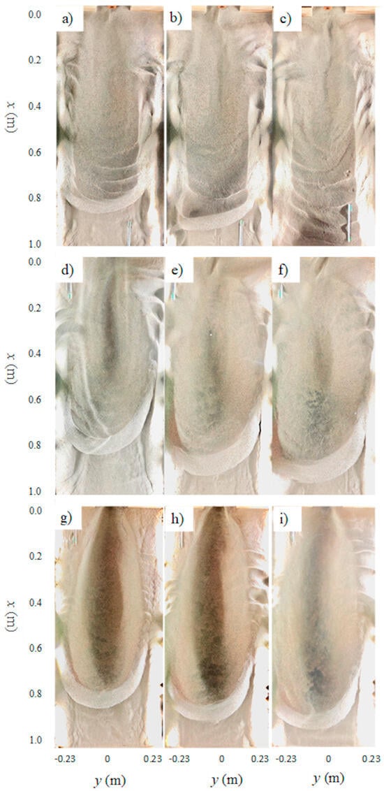
Figure 3.
Raw images of the impact of the tailwater in the sediment erosion for uniform sand particles from a circular wall jet with do = 12.7 mm at different flow rate: First row with a tailwater of 2do; (a) Q = 25 L/min; (b) Q = 28.5 L/min; (c) Q = 30.7 L/min; second row with a tailwater of 4do (d) Q = 25 L/min; (e) Q = 28.5 L/min; (f) Q = 30.7 L/min; and Third row with a tailwater of 6do (g) Q = 25 L/min; (h) Q = 28.5 L/min; and (i) Q = 30.7 L/min.
A larger eroded scour hole was observed as the discharge intensity increased. In unsubmerged (i.e., free flow) condition, the backflow is greater which resulted in the production of more ripples on the uniform beds. A larger number of ripples and the backflow noticeably influence the shape of the scour hole (see Figure 3a–c). The scour hole shows evidence of an irregular crest and high erosion in the vicinity of the nozzle exit, as it does in multi-density and size beds. As the tailwater increases, the backflow decreases. In the second and third rows of Figure 3, the ripples decrease considerably for partially and deeply submerged wall jets, and the jet produced more defined scour holes and less erosion near the jet exit. From Figure 3, it is evident how the jet diffusion is lower at a higher submerged ratio, meaning that the jet has a higher capacity to erode the bed.
Similar results were observed on the effects of discharge intensity and submergence from a 3D circular turbulent wall jet with slightly larger diameter (see Figure 4). As can be seen in Figure 4, when the wall jet is applied to the uniform-density sand bed, the top view of the scour hole takes an elliptical form. Similar shapes have been observed in the literature [10,14,33,34]. In such flow condition, the downstream dune height and the volume of deposited sediments are higher in comparison with the multi-size and density beds. The eroded scour hole tends to be larger in all the characteristic dimensions when the jet velocity increases. On the other hand, by increasing tailwater depth, the scour hole shape becomes more symmetric with a lower number of side ripples due to the absence of backflow, and only the longitudinal axis of the scour tends to increase. The transverse axis remains similar due to the interference of the side walls. At lower tailwater depths, Yt = 2do and 4do, the presence and the magnitude of the complex secondary backflow is evident. It causes greater erosion in the vicinity of the nozzle exit, as well as the presence of ripples in the opposite directions of the jet. At higher tailwater depths, the energy of the jet is conserved over distance, and such high energy produces larger scour holes. Less deposition is formed at the higher submergence level because sand particles wash out completely from the bed. On the other hand, for low tailwater depths, the jet does not have the possibility to wash out the bed particles outside the bed, producing higher deposition after the crest.
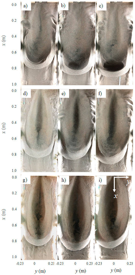
Figure 4.
Raw images of sediment erosion for uniform sand particles downstream of a circular wall jet with do = 25.4 mm for different flow rates and tailwater depths: First row Yt = 2do; (a) Q = 25 L/min; (b) Q = 28.5 L/min; (c) Q = 30.7 L/min; Second row Yt = 4do; (d) Q = 25 L/min; (e) Q = 28.5 L/min; (f) Q = 30.7 L/min; Third row (g) Yt = 6do, Q = 25 L/min; (h) Yt = 6do, Q = 28.5 L/min; and (i) Yt = 6do, Q = 30.7 L/min.
Figure 4 also shows a self-similarity between the transversal profiles for the uniform sand beds at higher submerged ratios when the flow velocity increases on a uniform bed. Most of the curves are described by a single curve (see Figure 4g–i), while for lower submerged ratios, the scour profiles became different when discharge increased (see Figure 4a–c). Unlike in Lim’s [12] study, the width of the scour hole in a narrow channel was recorded to establish how the lateral walls incise on the maximum width.
Figure 5 and Figure 6 show the effect of discharge intensity and submergence on scour formation on the multi-grain bed for do = 12.7 mm and 25.4 mm, respectively. As can be seen, an armor layer is formed in the middle of the scour area, and they are evident in all images. The armor layer is composed of lead balls, lead particles, and magnetite particles. Due to the size and density of the lead balls, they were always located in the center region of the scour hole and the lead and magnetite particles are in the surrounding area of the lead balls. The armor layer produces a narrower scour hole with irregular front dunes. The limited lateral jet expansion and the restriction by tailwater depth also affect the ridge shape, showing a flattened and open ridge in the presence of small tailwater level. At lower tailwater depth, Yt = 2do, the scour hole has a longer transverse axis and a smaller longitudinal axis. As the submergence of the jet is lowered, the jet diffusion increased and a higher disturbance on the water surface was observed.
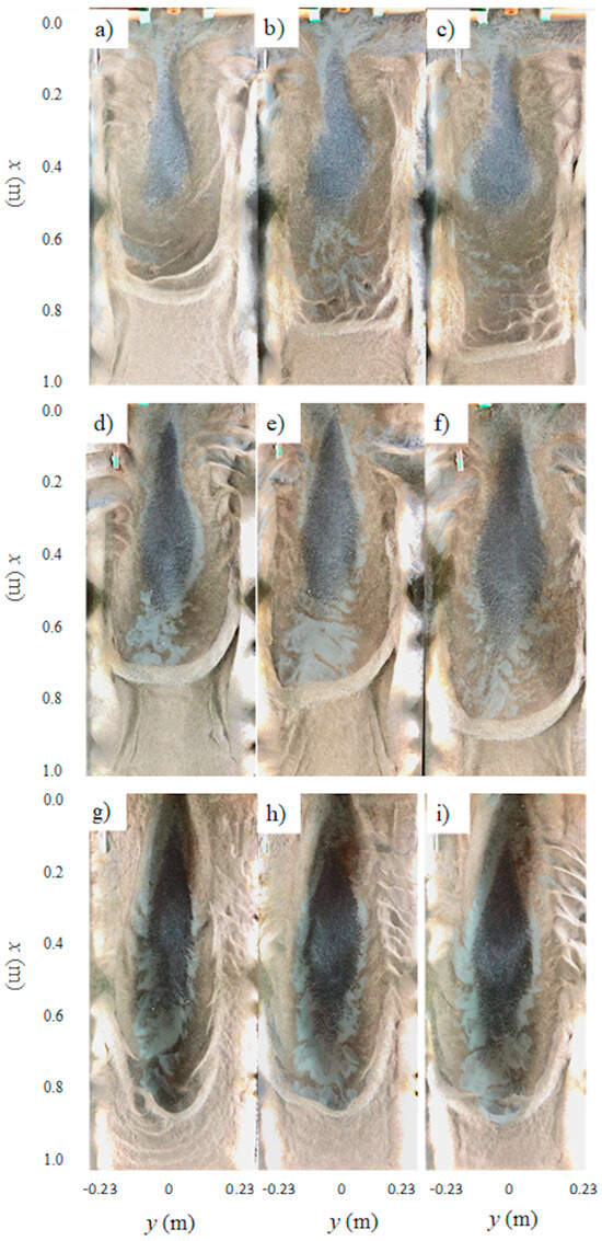
Figure 5.
Raw images of the impact of the tailwater in the sediment erosion of multi-density particles from a circular wall jet with do = 12.7 mm at different flow rate: First row with a tailwater of 2do, (a) Q = 25 L/min; (b) Q = 28.5 L/min; (c) Q = 30.7 L/min; Second row with a tailwater of 4do (d) Q = 25 L/min; (e) Q = 28.5 L/min; (f) Q = 30.7 L/min; and Third row with a tailwater of 6do (g) Q = 25 L/min; (h) Q = 28.5 L/min; and (i) Q = 30.7 L/min.
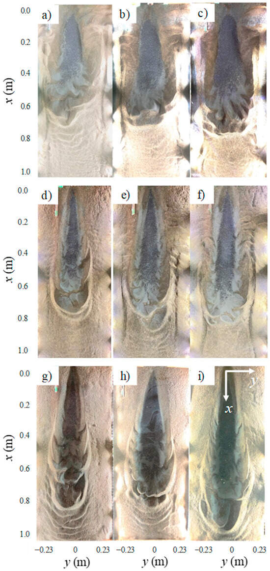
Figure 6.
Raw images of sediment erosion of multi-density particles downstream of a circular wall jet with do = 25.4 mm for different flow rates and tailwater depths: First row Yt = 2do, (a) Q = 25 L/min; (b) Q = 28.5 L/min; (c) Q = 30.7 L/min; Second row Yt = 4do, (d) Q = 25 L/min; (e) Q = 28.5 L/min; (f) Q = 30.7 L/min; Third row (g) Yt = 6do, Q = 25 L/min; (h) Yt = 6do, Q = 28.5 L/min; and (i) Yt = 6do, Q = 30.7 L/min.
It seems that in lower tailwater depths, the vortical flow is more intense and such flow structure causes higher erosion in the vicinity of the nozzle exit. For a constant submergence, the effect of flow intensity becomes negligible, as similar scour shapes are formed but with slightly higher segregation between particles. Considering erosion pattern from same discharge intensity, higher submergence elongated the scour. The jet energy is dissipated over the bed and such energy transfer causes particle separation and segregation. Images show that by increasing the jet velocity, the bed particles are spread over a larger area. Moreover, at higher submergence ratio, the semi-elliptical shape of the eroded bed tends to have a higher eccentricity. With increasing tailwater depth, the scour hole had a shorter transverse axis and a larger longitudinal axis.
When the tailwater increases and partially submerges the jet, the backflow decreases, and the jet diffusion decreases accordingly. The jet produces a higher scour hole at the same discharge and less erosion in the vicinity of the nozzle. In the same way, the irregularity of the crest is smaller, and the jet congregates heavier particles in more defined zones, producing three deposit areas. Figure 6g–i show the eroded area produced by a deeply submerged wall jet. As expected, the backflow is minimal with higher tailwater depths and as a result, the jet produces larger and deeper scour holes. Likewise, the jet produces more defined scour holes and, due to the low jet energy diffusion, the jet can congregate the materials in higher proportions.
3.2. Time Evolution of Scour
Figure 7 shows the effect of submergence on the time history of local erosion produced by a circular wall jet with do = 12.7 mm in multi-grain beds. Under the same discharge intensity, the scour holes are found to be larger than the erosion pattern illustrated in Figure 3. Due to the smaller nozzle size, the exit velocity is higher, and the jet has higher energy, which can cause deeper erosion. In smaller submergence, the wall jet can erode the vicinity of the nozzle. Owing to the low tailwater depth, the crest of the scour cannot be freely developed, and it is constantly eroded, producing an irregular border at the end of the scour hole. By increasing the intensity of the jet, the eroded area increases accordingly, but due to the jet diffusion on the water surface, the jet erodes a smaller proportion of the heavier particles and a large proportion of finer particles.
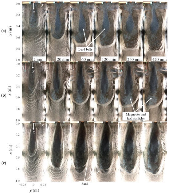
Figure 7.
Raw images of the evolution of the scour hole over time for a discharge of Q = 28 L/min for different tailwater depth and nozzle size of do = 12.7 mm: (a) Yt = 2do; (b) Yt = 4do; (c) Yt = 6do.
The evolution of the scour hole in multi-size and density bed at different tailwaters is shown in Figure 7. When the jet exits the nozzle, the erosion starts almost immediately, as well as the separation of different bed materials, because the flow shear velocity exceeds the critical shear stress of each particle on the bed. According to the intensity and progress of scouring, the scour process can be divided into four phases of (1) initiation, (2) development, (3) stabilization, and (4) equilibrium phase [38]. At t = 2 min, the scour hole is forming, so it is on the initiation phase. The scour hole is larger when the tailwater is higher, since the jet exerted from the nozzle is more concentrated. At t = 20 min, the scour hole is in the development phase, and the downstream section of the growing scour hole stabilizes until it reaches the next phase. The scour hole on multi-size and density beds seems to be almost developed at the same time of t = 60 min, regardless of tailwater depth. The rate of scour formation becomes slower once the scouring process reaches the stabilization phase. The eroded bed shows small differences in the scour hole characteristics after the development phase (i.e., t = 60 min) due to formation of the armor layer that reduces the growth rate of the scour hole. At t = 120 min, the characteristic length of scour does not change significantly, and the scour area is modified.
Figure 8 shows the modified images to analyze the evolution of the occupied areas of each particle in the scour hole over time. Finally, at t = 420 min, the scour hole is in an equilibrium phase when it remains virtually unchanged. By temporally developing the scour hole in a multi-density sand bed, the lead balls, magnetite, and lead particles are revealed, separated, and deposited, and they make distinct areas in the scour hole. The scour hole shows three rings, which are composed of different materials. The first ring is composed of the lead balls, the second is composed of the lead particles and magnetite particles, and the third ring is composed of sand particles. All three rings appear simultaneously. Over time, each region grows bigger and more defined over time.
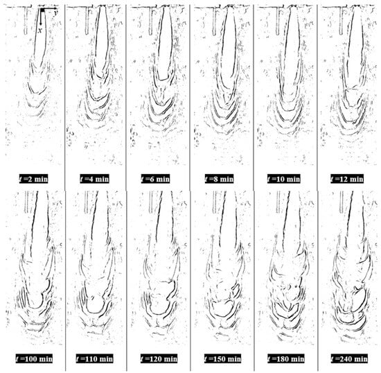
Figure 8.
Evolution of the scour hole over the time for bed erosion of multi-size and density particles with a discharge of Q = 25 L/min for a tailwater depth of Yt = 6do and nozzle size jet of do = 25.4 mm processed with a MATLAB algorithm.
3.3. Scour Profiles
Figure 9 shows the effects of flow intensity and submergence in variations of normalized scour depth for uniform beds over distance. As it was expected, at lower submergence range the erosion near the nozzle is higher. As the jet intensity increases, the scour size increases accordingly, and such growth is independent of the tailwater depth. However, at higher submergence, the scour hole is deeper and larger. The position of the maximum depth does not change if the tailwater depth changes (see Figure 9). Because the shape of the scour hole does not change significantly with tailwater depth, it could be described by a single curve.
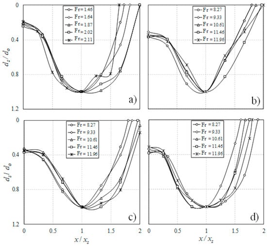
Figure 9.
Correlations of non-dimensional scour profiles ds/do for uniform sand particles in equilibrium state, t = 420 min: (a) Yt/do = 2; (b) Yt/do = 4; (c) Yt/do = 8; (d) Yt/do = 12.
Figure 10 shows the effects of flow intensity and submergence on variations of normalized scour profile over the distance. As reported by Kells [39], the multi-size and density beds show scour profiles with two sequence holes. The second scour hole seems to be independent of the densimetric Froude number and the tailwater depth. Therefore, the first hole near the nozzle is shown in Figure 10. As can be seen, the maximum scour depth increases with increasing jet Froude number, and they are independent of submergence. Figure 10a,b shows scour profile in relatively shallow water and Figure 10c,d shows the scour profiles in relatively deep submergence. In free flow condition, the expected scour hole is smaller than what is produced by a submerged wall jet due to the jet’s diffusion. When the tailwater is low, the jet’s energy is mainly dissipated by water surface fluctuation, which results in the formation of shorter and shallower scour holes.
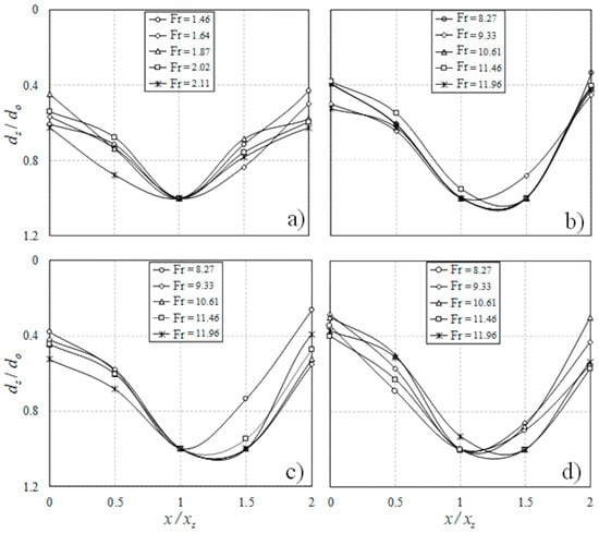
Figure 10.
Correlations of non-dimensional scour profiles ds/do for multi-size and density particles beds in equilibrium state, t = 420 min: (a) Yt/do = 2; (b) Yt/do = 4; (c) Yt/do = 8; (d) Yt/do =12.
As can be seen in Figure 10a,b it is evident how the backflow eroded the vicinity of the jet in comparison with the submerged wall jets. In relatively shallow submergence, the strong backflow at both sides of the nozzle is influenced by the channel width and such backflow causes additional scour near the vicinity of the nozzle (see Figure 10a). In moderately submerged wall jets, the backflow causes differences in the scour hole shape, mainly on the region before the location of the maximum scour depth, so the scour hole no longer maintains the shape that was observed in deeply submerged conditions (see Figure 10b). In a deeply submerged flow condition (i.e., Yt/do = 12), the jet permits almost unbounded expansion downstream of the jet in streamwise, vertical, and transversal directions. On confined channels, the position of the maximum scour depth is almost independent of discharge and tailwater depth, with a value of near ds/do = 1.
4. Discussion
4.1. Scour Dimensions
Figure 11 shows the correlations of the maximum scour depth with the densimetric Froude number in the equilibrium state, t = 420 min, to develop a prediction model of the equilibrium scour depth at the centerline of scour for different tailwater depths (i.e., submergence levels). As it was reported by Aderibigde and Rajaratnam [13], lighter bed materials moved out from the scour hole and the coarse materials (i.e., lead balls) are mainly deposited at the maximum depth of the scour. Hence, determination of the effective diameter that better represents the maximum scour depth was necessary, and the use of the diameter of the coarser materials seems to be correct.
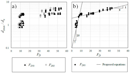
Figure 11.
Variations of the non-dimensional equilibrium scour depth downstream of a circular jet for both uniform and multi-density particle beds with different Densimetric Froude numbers: (a) FD50 and FD85; (b) FD95.
Figure 11a shows the correlation between the normalized maximum scour depth and the densimetric Froude number calculated employing the median grain size, D50, and the grain size for which 85% of materials are finer, D85, respectively. The scatter on such relationship is high, showing that it is not suitable for any prediction. Figure 11b shows the correlation of the normalized maximum scour depth with the densimetric Froude number, FD95. The densimetric Froude number calculated is based on the grain size for which 95% of materials are finer, D95, and shows less scatter (see Figure 11b). The relationship produces a piecewise linear equation that has two slopes. The equation is proposed for FD95 ≤ 12 and FD95 > 12, in accordance with other researchers [12,16,40] who established ranges to predict the maximum scour depth. Lim [12] established FD50 = 10 as the point where the slopes of the equations dramatically changed. It seems that for lower densimetric Froude numbers, FD95 ≤ 12, the rate of increase is higher for the normalized maximum scour depth than the rate of increase for higher densimetric Froude numbers, FD95 > 12. Figure 11b shows that most of the data is close together in a well-defined band, showing a strong correlation between the dsmax/do with the FD95, which can be expressed as:
The coefficient of determination of the above equations are R2 = 0.978 for the first stretch, and R2 = 0.920 for the second stretch. It is reasonable to use a coarser particle diameter that is representative of the bed mixture after the erosion. The logic is that the coarser particles that remained on the eroded bed formed a coarse layer and the finer particles on the top layer of the eroded bed were washed away by the turbulent resuspension mechanism. As was reported by Lim [12], for narrow channels the trend between the normalized maximum scour depth shows a strong relationship with the densimetric Froude number, and the effect of the channel width, nozzle shape, and the tailwater are less significant in comparison with FD for confined channels (see Figure 11). The increase of the jet Froude number, Fr, seems to have a lower effect on the increment of the maximum width for both beds, since the channel walls restrict the normal diffusion of the jet and do not allow free growth of this dimension in the transversal direction [12,40].
Figure 12 shows the variation of maximum scour width, wsmax, normalized with the nozzle size, do, with densimetric Froude number, FD. Same as in Figure 11, choice of the effective diameter that better describes the maximum width was necessary. The use of the mean diameter, D50, shows a better relationship between the normalized maximum width with the nozzle diameter, wsmax/do, and the densimetric Froude number, FD50. An empirical model was proposed for prediction of scour depth, which is expressed as:
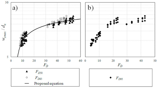
Figure 12.
Variations of the non-dimensional maximum scour width downstream of a circular jet for both uniform and multi-density particle beds with different Densimetric Froude number: (a) FD50 and FD85; (b) FD95.
The coefficient of determination of the above equation is R2 = 0.934. The different variations of normalized maximum scour width with the densimetric Froude number proposed based on FD85 and FD95 and those correlations show greater scatter, rendering undesirable their use to predict the characteristic dimension of the scour hole. In a narrow channel, the side walls restrict the lateral diffusion of the jet, hence the jet flow momentum is concentrated and increases the bed scour length in the streamwise direction [12,41].
As is depicted in Figure 13, the variation of the maximum scour length, ls, for both multi-size and density bed and uniform beds can be analyzed by plotting ls/do as a function of densimetric Froude number, FD. The process to find the effective diameter that best describes the relationship between these two variables is the same as in Figure 11. It was found that the diameter that shows the lower scatter is the densimetric Froude number calculated with mean diameter, D50, and the proposed prediction equation of maximum scour length can be described as
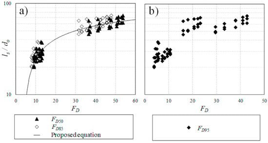
Figure 13.
Variations of the non-dimensional maximum scour length downstream of a circular jet for both uniform sand and multi-density particle beds with different Densimetric Froude numbers: (a) FD50 and FD85; (b) FD95.
As can be seen in Figure 11, the scour depth in multi-grain size and density was correlated with the densimetric Froude number using D95, whereas Figure 12 and Figure 13 show that both scour width and length were correlated with densimetric Froude number based on D50. Such correlations emphasize the hypothesis that the armoring effect significantly reduces the scour depth while it has less impact on the spreading and length of scour. The proposed hypothesis based on the obtained results is limited to the tested range of jet Froude number (1.46 ≤ Fr ≤ 11.96), densimetric Froude number (4.02 ≤ FD ≤ 42.83), and submergence ratio of 2 ≤ Yt/do ≤ 12.
Figure 14 shows a comparison of the normalized maximum scour depth that was predicted from current experiments and the experiments conducted by other researchers [11,12,13,31,39,40,41]. The scour induced by 2D turbulent wall jets were mainly conducted for low densimetric Froude numbers, and as expected, the scour hole produced by a 2D wall jet shows larger values of maximum scour depth. On the other hand, the erosion induced by a 3D wall jet shows smaller values at maximum depth. A significant difference in the values for this length denotes the large differences in the scour process. As Figure 14 shows, the 2D and 3D jet data tend to be grouped in different zones of the graph. The 2D and 3D data also show different slopes of prediction. Uniform sand beds data show that the maximum depth is much lower than the values produced by the jet under free flow conditions. On the other hand, the multi-size and density beds clearly show the effect of armor layer and the confinement of the tank. The maximum depth produced by the jet is lower in comparison to the data presented by other researchers. However, such effect is more appreciable for higher densimetric Froude numbers, reducing the values of the maximum depth by almost 50%.
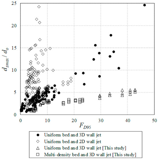
Figure 14.
Correlation of the non-dimensional maximum scour depth dsmax/do with densimetric Froude number in transient flow condition.
4.2. Bed Material Segregation
On multi-size and density beds, the jet deposits the coarser material at the center of the scour hole and covers the coarser materials with finer materials layer by layer, forming rings. In this experiment, it is evident that the three groups of layers were lead balls, magnetite, and lead particles, and finally sand particles. Figure 15a shows the percentage of each area that the jet can group on the scour hole and the change in each case due to the effects of flow intensity and submergence. The number in the horizontal axis of Figure 15 is the jet Froude number, Fr. The coarser materials, as expected, are in the top layer of the scour hole for each experiment, creating the armoring effect. Figure 15b shows that for submerged jets and at lower velocity, the area covered by the lead balls is smaller. When the jet velocity increases, the area of the lead balls increases as well, indicating the effect of energy transfer in spreading large and heavier particles. In the confined channel, the tailwater slightly affects the percentage of lead balls that jet can group, especially when the jet is submerged. However, in the presence of deep submergence, increasing flow intensity does not increase the area of lead balls.
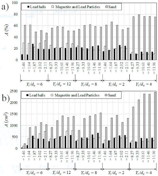
Figure 15.
Effects of Froude number and tailwater depth on the eroded area of different particles in mixed bed tests; (a) Areas in percentage; (b) Areas in cm2.
The largest area of the grouped lead balls occurs at a tailwater ratio of 8 and jet Froude number of 11.96 (see Figure 15b). The second area more noticeable on the scour hole is the magnetite and lead particles which are depicted in gray color (see Figure 5 and Figure 6). These particles surround the coarser material, and it is evident that at lower tailwater depths, the area of those particles becomes smaller due to the jet’s diffusion (see Figure 15b). In a confined channel and shallow submergence, when the relationship between nozzle size and tailwater depth is equal to 4, particles are mainly deposited at the vicinity of the nozzle and the percentage of the deposit area is similar for all flow intensities. The higher areas of magnetite and lead particles occur at the deeply submerged condition when the tailwater is 12 times that of the nozzle diameter. Diffusion is lower at higher tailwaters, and the jet can move heavier particles more easily. Increasing the jet Froude number increased the area of deposition while submergence reduced the overall area of deposition. For instance, the area of sand particles reduced by more than 50% when Yt/do increased from 4 to 12 while Fr is constant with a value of 8.27. For constant submergence of Yt/do = 2, increasing Fr from 1.46 to 2.11 increased the area of lead balls by 120%. Whereas in higher submergence of Yt/do = 6, such incrementing of the jet Froude number increased the area of lead balls by more than five times.
Finally, the last group of particles noticeable on the scour hole is the eroded sand that surrounds the magnetite and lead particles. The percentage of the area does not increase significantly when tailwater depth is changed; however, when the tailwater ratio is low or the jet is unsubmerged, the eroded area of sand particles is notably bigger at higher flow intensities and such change is due to the presence of stronger backflow. The jet in shallow submergence is diffused predominantly at the water surface and cannot penetrate the bed as much. Thus, at a tailwater depth of 0.0508 m and nozzle size of 0.0127 m, the area of sand particles is the largest.
5. Conclusions
A series of laboratory experiments was carried out to study the effects of flow intensity and submergence on the scour formation induced by circular turbulent wall jets on uniform sand and multi-grain size and density beds. The geometric characteristics of scour, such as scour depth, width, and length, were measured and the results were compared with scour dimensions induced by the same jets on uniform sand bed as benchmark tests. The following conclusions were made from the experimental results:
- The comparison revealed that the effects of particle segregation and armoring on the scour development in multi-grain size and density is significant.
- It was found that the eroded area of different particle types increased with the jet intensity, but the erosion of relatively heavier particles was limited due to jet diffusion.
- Four stages of initiation, development, stabilization, and equilibrium were identified and the corresponding times for each stage was determined from image analysis. It was observed that the development phase is achieved after an hour of jet discharge initiation and the growth rate of scouring reduced due to formation of an armor layer.
- The scour area reached an equilibrium phase after approximately two hours from the initiation of the experiment and the final equilibrium stage was achieved at 420 min. At the equilibrium stage, the scour hole consists of three rings made by three bed materials.
- It was found that the erosion is higher near the nozzle at low submergence and the scour hole is larger and deeper as the jet intensity increases.
- A densimetric Froude number based on D95 can properly describe the correlation between flow intensity and maximum scour in a multi-grain size and density bed. Two linear models were proposed to describe the correlation between normalized peak scour depth and densimetric Froude number with a threshold value of FD95 = 12.
- Data analysis for prediction of scour width and length indicated that a densimetric Froude number based on D50 provides the best fit. Non-linear models were proposed for prediction of maximum scour width and length in multi-grain size and density beds.
- The effect of submergence in suppressing jet diffusion was evident in variations of lead and magnetite particles. In lower tailwater depths, the area covered by the lead and magnetite particles reduced due to jet diffusion. Therefore, the highest area of lead and magnetite particles occurred in deeply submerged flow conditions. The jet in shallow submergence was diffused predominantly at the water surface and did not penetrate efficiently towards the bed. Therefore, the area of sand particles was found to be higher in the presence of low submergence.
- It should be noted that the proposed models based on the obtained results are limited to the tested range of jet Froude number (1.46 ≤ Fr ≤ 11.96), densimetric Froude number (4.02 ≤ FD ≤ 42.83), and submergence ratio of 2 ≤ Yt/do ≤ 12.
- The result of the present study is limited to the scouring induced by a three-dimensional circular wall jet in confined channels. The effect of channel confinement in the generation of backflow was evident and such backflow affected the shape of the scour profile in multi-grain size and density beds. Therefore, future studies are needed to evaluate the effects of channel width to nozzle diameter ratio on scour characteristics.
Author Contributions
Conceptualization, A.H.A.; methodology, H.H.; formal analysis, H.H.; investigation, H.H.; resources, A.H.A.; data curation, H.H.; writing—original draft preparation, H.H.; writing—review and editing, A.H.A.; visualization, H.H. and A.H.A.; supervision, A.H.A.; project administration, A.H.A.; funding acquisition, A.H.A. All authors have read and agreed to the published version of the manuscript.
Funding
This research was funded by the Natural Science and Engineering Research Council of Canada (NSERC) grant number 421785.
Institutional Review Board Statement
Not applicable.
Informed Consent Statement
Not applicable.
Data Availability Statement
The raw data supporting the conclusions of this article will be made available by the authors on request.
Conflicts of Interest
The authors declare no conflict of interest.
Notations
The following symbols were used in this thesis:
| A | magnitude of area occupied by specific particles, m2 |
| Ao | nozzle area, m2 |
| B | flume wide, m |
| do | jet pipe size, m |
| ds | scour depth, m |
| dsmax | maximum scour depth, m |
| D | bed particle size, mm |
| D16 | grain size for which 16% of material is finer, mm |
| D50 | median grain size, mm |
| D85 | grain size for which 85% of material is finer, mm |
| D95 | grain size for which 95% of material is finer, mm |
| FD | densimetric Froude number |
| FDi | densimetric Froude number defined with the bed material for i % of which is fine by weight |
| Fr | jet Froude number |
| g | acceleration due to gravity, m/s2 |
| Kd; KD; Kf; KL; Ks; Kσ | constants |
| lc | critical shear stress length, m |
| ls | maximum scour length, m |
| L | total length of the bed, m |
| m | mass of particles, kg |
| Q | discharge, L/min |
| Re | jet Reynolds number |
| RH | hydraulic radius, m |
| Re* | boundary Reynolds number |
| t | time, s |
| T | time scale, s |
| uo | initial jet velocity, m/s |
| u* | shear velocity, m/s |
| ws | scour width, m |
| wsmax | maximum scour width, m |
| x | longitudinal axis, m |
| xs | location of the maximum scour depth from nozzle, m |
| y | transversal axis, m |
| Yt | tailwater depth, m |
| z | vertical axis, m |
| V | volume occupied by the mass, m3 |
| ν | kinematic viscosity, m2/s |
| Δρp | density difference between the bed particles and the fluid, kg/m3 |
| ρp | density of particle, kg/m3 |
| ρw | density of water, kg/m3 |
| σg | geometric standard deviation of bed material size |
| τb | bed shear stress, Pa |
| τc | critical shear stress, Pa |
References
- Azimi, A.; Zhu, D.; Rajaratnam, N. Experimental study of subaqueous sand deposition from slurry wall jets. J. Eng. Mech. 2014, 140, 296–314. [Google Scholar] [CrossRef]
- Manzouri, M.; Azimi, A.H. Laboratory experiments evaluating sedimentation and mound formation of obliquely discharged sand particles in stagnant water. Int. J. Sediment Res. 2019, 34, 564–576. [Google Scholar] [CrossRef]
- Manzouri, M.; Azimi, A.H. Effects on oily sand jet evolution from impact momentum and channelization of particles through an immiscible interface. Int. J. Multiph. Flow 2019, 121, 103124. [Google Scholar] [CrossRef]
- Pandey, M.; Valyrakis, M.; Qi, M.; Sharma ALodhi, A.S. Experimental assessment and prediction of temporal scour depth around a spur dike. Int. J. Sediment Res. 2021, 36, 17–28. [Google Scholar] [CrossRef]
- Baranwal, A.; Das, B.S. Live-bed scour depth modelling around the bridge pier using ANN-PSO, ANFIS, MARS, and M5Tree. Water Resour. Manag. 2024, 38, 4555–4587. [Google Scholar] [CrossRef]
- Bombardelli, F.A.; Palermo, M.; Pagliara, S. A general theoretical framework for equilibrium scour due to inclined jets based on the Phenomenological Theory of Turbulence. Phys. Fluids 2025, 37, 083425. [Google Scholar] [CrossRef]
- Buffon, P.; Uijttewaal, W.S.J.; Valero, D.; Franca, M.J. Evolution of Erosion and Deposition Induced by an Impinging Jet to Manage Sediment. Water Resour. Res. 2025, 61, WR038657. [Google Scholar] [CrossRef]
- Rajaratnam, N.; Pani, B.S. Three-dimensional turbulent wall jets. J. Hydraul. Div. 1974, 100, 69–83. [Google Scholar] [CrossRef]
- Rajaratnam, N.; Berry, B. Erosion by circular turbulent wall jets. J. Hydraul. Res. 1977, 15, 277–289. [Google Scholar] [CrossRef]
- Rajaratnam, N. Erosion by plane turbulent jets. J. Hydraul. Res. 1981, 19, 339–358. [Google Scholar] [CrossRef]
- Chatterjee, S.S.; Ghosh, S.N.; Chatterjee, M. Local scour due to submerged horizontal jet. J. Hydraul. Eng. 1994, 120, 973–992. [Google Scholar] [CrossRef]
- Lim, S.Y. Scour below unsubmerged full-flowing culvert outlets. Proc. Inst. Civ. Eng.-Water Marit. Energy 1995, 112, 136–149. [Google Scholar]
- Aderibigbe, O.; Rajaratnam, N. Effect of sediment gradation on erosion by plane turbulent wall jets. J. Hydraul. Eng. 1998, 124, 1034–1042. [Google Scholar] [CrossRef]
- Balachandar, R.; Kells, J.A.; Thiessen, R.J. The effect of tailwater depth on the dynamics of local scour. Can. J. Civ. Eng. 2000, 27, 138–150. [Google Scholar] [CrossRef]
- Dey, S.; Sarkar, A. Effect of upward seepage on scour and flow downstream of an apron due to submerged jets. J. Hydraul. Eng. 2007, 133, 59–69. [Google Scholar] [CrossRef]
- Melville, B.W.; Lim, S.Y. Scour caused by 2D horizontal jets. J. Hydraul. Eng. 2014, 140, 149–155. [Google Scholar] [CrossRef]
- Aamir, M.; Ahmad, Z. Review of literature on local scour under plane turbulent wall jets. Phys. Fluids 2016, 28, 105102. [Google Scholar] [CrossRef]
- Zhao, P.; Yu, G.; Zhang, M. Local Scour on Noncohesive Beds by a Submerged Horizontal Circular Wall Jet. J. Hydraul. Eng. 2019, 145, 06019012. [Google Scholar] [CrossRef]
- Hernandez, H.; Mostaani, A.; Azimi, A.H. Segregation of particles in multi size and density beds by circular wall jets. In Canadian Society of Civil Engineering Annual Conference; Springer: Singapore, 2021; pp. 211–221. [Google Scholar]
- Li, G.; Wang, B. Simulation of the flow field and scour evolution by turbulent wall jets under a sluice gate. J. Hydro-Environ. Res. 2022, 43, 22–32. [Google Scholar] [CrossRef]
- Hernandez, H.; Azimi, A.H. Effect of armor layer on the local scour formation induced by a deeply submerged circular wall jet in confined channels. Can. J. Civ. Eng. 2023, 50, 510–522. [Google Scholar] [CrossRef]
- Khuntia, J.R.; Devi, K.; Mumtaz, M.A. Modeling of scour hole characteristics under turbulent wall jets using machine learning. Sci. Rep. 2024, 14, 15567. [Google Scholar] [CrossRef]
- Samma, H.; Khosrojerdi, A.; Rostam-Abadi, M.; Mehraein, M.; Cataño-Lopera, Y. Numerical simulation of scour and flow field over movable bed induced by a submerged wall jet. J. Hydroinform. 2020, 22, 385–401. [Google Scholar] [CrossRef]
- Si, J.; Lim, S.; Wang, X. Evolution of Flow Fields in a Developing Local Scour Hole Formed by a Submerged Wall Jet. J. Hydraul. Eng. 2020, 146, 04020040. [Google Scholar] [CrossRef]
- Yan, X.; Mohammadian, A.; Rennie, C. Numerical modeling of local scour due to submerged wall jets using a strict vertex-based, terrain conformal, moving-mesh technique in OpenFOAM. J. Sediment Res. 2020, 35, 237–248. [Google Scholar] [CrossRef]
- Nazarimehr, F.; Ghodsian, M. Experimental study of scour characteristics by circular turbulent impinging jets in cohesive soils. ISH J. Hydraul. Eng. 2025, 31, 443–460. [Google Scholar] [CrossRef]
- Salehi, S.; Mostaani, A.; Azimi, A.H. Experimental and numerical investigations of flow over and under weir-culverts with a downstream ramp. J. Irrig. Drain. Eng. 2021, 147, 04021029. [Google Scholar] [CrossRef]
- Salehi, S.; Azimi, A.H.; Heidarpour, M. Hydraulic properties and local scour downstream of permeable grade-control structures. J. Irrig. Drain. Eng. 2024, 150, 0402402. [Google Scholar] [CrossRef]
- Salehi, S.; Azimi, A.H. Effects of spoiler and piggyback on local scour under single and twin submerged pipes. Ocean Eng. 2022, 261, 112137. [Google Scholar] [CrossRef]
- Ali, K.H.M.; Lim, S.Y. Local scour caused by submerged wall jets. Proc. Inst. Civ. Eng. 1986, 81, 607–645. [Google Scholar] [CrossRef]
- Dey, S.; Sarkar, A. Scour downstream of an apron due to submerged horizontal jets. J. Hydraul. Eng. 2006, 132, 246–257. [Google Scholar] [CrossRef]
- Sarathi, P.; Faruque, M.A.A.; Balachandar, R. Influence of tailwater depth, sediment size and densimetric Froude number on scour by submerged square wall jets. J. Hydraul. Res. 2008, 46, 158–175. [Google Scholar] [CrossRef]
- Rajaratnam, N.; Macdougall, R.K. Erosion by plane wall jets with minimum tailwater. J. Hydraul. Eng. 1983, 109, 1061–1064. [Google Scholar] [CrossRef]
- Blaisdell, F.W.; Anderson, C.L. A comprehensive generalized study of scour at cantilevered pipe outlets. J. Hydraul. Res. 1988, 26, 509–524. [Google Scholar]
- Lavaei, H.; Esmaeili, M.; Mehraein, M. Enhanced prediction of scour dimensions: Temporal variations induced by turbulent plane wall jets using FFNN, CatBoost, and XGBoost models. Ocean. Eng. 2025, 333, 121539. [Google Scholar] [CrossRef]
- MathWorks. Matlab User Manual; Math Works: Natick, MA, USA, 2018. [Google Scholar]
- Ade, F.; Rajaratnam, N. Generalized study of erosion by circular horizontal turbulent jets. J. Hydraul. Res. 1998, 36, 613–636. [Google Scholar] [CrossRef]
- Hoffmans, G.J.C.M.; Verheij, H.J. Scour Manual; A.A. Balkema: Rotterdam, The Netherlands, 1997. [Google Scholar]
- Kells, J.A.; Balachandar, R.; Hagel, K.P. Effect of grain size on local channel scour below a sluice gate. Can. J. Civ. Eng. 2001, 28, 440–451. [Google Scholar] [CrossRef]
- Rajaratnam, N.; Diebel, M. Erosion Below Culvert-like Structures. In Fifth Canadian Hydrotechnical Conference; CSCE: Fredericton, NB, Canada, 1981; pp. 469–484. [Google Scholar]
- Faruque, M.; Sarathi, P.; Balachandar, R. Clear Water Local Scour by Submerged Three-Dimensional Wall Jets: Effect of Tailwater Depth. J. Hydraul. Eng. 2006, 132, 575–580. [Google Scholar] [CrossRef]


Disclaimer/Publisher’s Note: The statements, opinions and data contained in all publications are solely those of the individual author(s) and contributor(s) and not of MDPI and/or the editor(s). MDPI and/or the editor(s) disclaim responsibility for any injury to people or property resulting from any ideas, methods, instructions or products referred to in the content. |
© 2026 by the authors. Licensee MDPI, Basel, Switzerland. This article is an open access article distributed under the terms and conditions of the Creative Commons Attribution (CC BY) license.