Abstract
This study presents a compact, 3D-printed Savonius wind turbine rotor incorporating pointed deflectors to enhance concave-side airflow and mitigate blade-edge vortex formation. The prototype, fabricated from ABS plastic, was experimentally evaluated in an Eiffel-type wind tunnel under low-speed wind conditions (3, 4, and 5 m/s), with blockage effects taken into account. Flow visualization revealed improved airflow attachment and pressure concentration on the concave blade surfaces, increasing drag asymmetry and torque generation. Corresponding power coefficients with applied blockage ratio were observed to be 0.181, 0.185 and 0.186, while torque coefficients with applied blockage ratio were observed to be 0.385, 0.374 and 0.375 at each wind speed and optimal tip-speed ratio, respectively, and were compared with previously reported computational results. The optimal operating tip-speed ratios identified for the torque and power coefficients were remarkably close, enabling efficient torque and power generation during operation. The experimental findings validate earlier numerical predictions and underscore the importance of physical testing in assessing turbine performance. Observed deviations between predicted and experimental coefficients suggest that fabrication parameters may influence prototype performance and warrant further investigation. Overall, the results demonstrate the technical viability of 3D-printed Savonius turbines for small-scale urban energy harvesting applications in the Philippines.
1. Introduction
The Philippine power sector faces persistent challenges stemming from its archipelagic geography and fragmented, predominantly privatized power generation, transmission, and distribution systems [1,2]. As a result, power production in the Philippines remains dominated by coal and natural gas, which accounted for approximately 64.46% and 14.21% of gross power generation in 2024, respectively, reflecting a continued dependence on fossil-fuel-based generation [3]. This reliance on fossil fuels directly conflicts with the Philippines’ commitments under the Paris Agreement, as articulated in the Renewable Energy Act of 2008, to reduce greenhouse gas emissions and transition to low-carbon energy systems [4]. Although feasibility studies conducted by the German–Philippine Chamber of Commerce and Industry and the Global Wind Energy Council identified significant renewable energy (RE) potential for solar, hydrogen and wind, deployment and adoption remain limited due to a perceived lack of government support and incentivization for private energy providers [5,6,7]. Further prospective analysis on coastal and island localities showed that the country’s varied landscape is well-suited for RE integration, given the abundant access to solar, tidal, and wind resources [8,9,10,11]. Despite this potential, wind energy remains severely underutilized, accounting for less than 1% of total energy generation in 2024, highlighting a significant gap in resource utilization and implementation [3].
A major limiting factor of wind power is hourly and seasonal wind variability, which can greatly affect the power output of large-scale on-grid plants and overall grid stability [12]. As an alternative, smaller off-grid wind systems may serve as supplementary power sources, delivering electricity directly to homes and businesses alongside on-grid transmission or other RE systems. However, these systems are typically only viable for wind-rich, unobstructed locations like elevated or coastal areas, limiting their applicability in dense urban environments. Wind resource collection mainly utilizes wind energy from the urban canopy and obstructed urban terrain, which is characterized by low wind speeds and high turbulence [13]. In urban settings, wind energy integration has been explored through building-integrated wind turbines (BIWTs) that take advantage of airflow characteristics around buildings, often as a complement to solar systems [13,14]. Bošnjaković et al. [15] identified that, while BIWTs may offer a contributory solution to decarbonization, current implementation remains costly due to low capacity, short operation life, and high building integration costs. This approach is compounded by considerable hurdles in tropical environments, where extreme climate and weather events can damage and destroy infrastructure [16]. Therefore, urban wind power generation calls for robust, scalable wind energy systems that can be effectively integrated into existing tall structures like skyscrapers.
Savonius wind turbines, a type of vertical-axis wind turbine (VAWT), specialize in operating in variable and low-wind-speed conditions [17]. Savonius wind turbines are drag-based, economical designs due to their simplicity, operation independent of wind direction, self-starting capabilities, and low vibration and noise [18]. These capabilities make Savonius wind turbines ideal for urban and semi-urban settings through integration with existing infrastructure [19,20]. Previous literature has also highlighted the advantages of VAWT configurations over horizontal-axis wind turbines (HAWTs) in urban environments, where wind is often turbulent and flow patterns are more complex [13].
Despite these advantages, conventional Savonius turbine designs suffer from low efficiency and high negative torque, thereby limiting their adoption in the wind energy industry [21,22]. Savonius wind turbines rely on the pressure differential between the concave and convex sides of the blades to produce useful rotational energy. The force on the concave side of the advancing blade must be more than the force on the convex side of the returning blade to generate positive torque [23]. However, negative torque can be generated by opposing forces acting on the returning side of the rotor blade, which inhibits power generation and turbine efficiency.
Previous studies have focused on the manipulation of rotor blade characteristics to enhance turbine performance. Chaichana and Thongdee [24] reported that increasing the blade number and adjusting blade angle enhanced the power coefficient of H-type Savonius turbines, with optimal performance observed at a 16-blade configuration and a 5° blade angle. In contrast, Wenehenubun et al. [25] observed that a three-bladed Savonius wind turbine outperformed two- and four-bladed configurations at high tip-speed ratios, highlighting the significance of operating conditions on optimization. Geometric modifications have also been shown to influence turbine performance. Abdelaziz et al. [26] found that varying the outer- and inner-blade arc angles improves turbine efficiency by up to 13% compared to the conventional design. Loganathan et al. [27] observed a 50% increase in performance when the rotor diameter was doubled, demonstrating the influence of rotor size and scale on energy capture and power output.
Blade tip modifications, like endplates and other tip modification devices, are considered one of the simplest methods of improving aerodynamic performance [28]. Endplates redirect incoming air towards the advancing blade and mitigate flow leakage near the blade edges, thereby increasing the pressure differential between the convex and concave sides of the blade and increasing overall turbine efficiency [29]. Wong et al. [30] reported substantial performance improvement using a circular endplate design, which was attributed to the reduction in spanwise spillage and improved rotor aerodynamics. Similarly, Wang et al. [31] observed performance improvements across eight different endplate designs, indicating that flow leakage suppression along the blade edges has a dominant role in performance enhancement. However, endplates may also induce parasitic drag on the blade tips, highlighting the need to balance airflow directionality against aerodynamic losses when optimizing endplate designs. While substantial research has focused on the general effectiveness of endplates on turbine performance, few studies have explored their efficacy on small-scale Savonius wind turbines. This gap in research highlights the need for further research to identify the performance of various designs under low-wind-speed and size-constrained operating conditions.
Contemporary research in Savonius wind turbine optimization has been bolstered by rapid advancements in powerful computational analysis techniques like computational fluid dynamics (CFD) [29,32,33,34,35], finite element analysis (FEA) [36,37], and artificial intelligence (AI) [38,39,40]. These in silico techniques offer immediate design feedback and optimization in the pre-prototype phase of development. However, experimental validation of computational results is key to the scientific process. Experimental characterization of 3D-printed experimental prototypes of Savonius wind turbines has also been explored in the previous literature, with 3D printing offering a rapid, cost-effective, and accessible approach to prototype fabrication, enabling the use of materials with diverse physical properties [41,42]. This, coupled with numerical simulation testing methods, creates a robust and rapid pipeline for design optimization, fabrication, and testing. Three-dimensional-printed Savonius wind turbine rotors have been explored in previous research using plastic fused deposition modeling (FDM) [43,44] and laser printing [45], demonstrating the method’s low-cost, expeditious manufacturing capabilities that enable rapid design optimization.
This study presented a compact, 3D-printed Savonius wind turbine rotor with pointed deflectors designed to enhance concave-side airflow and reduce blade-edge vortex formation. The design of the fabricated prototype was developed in a previous study, which characterized the performance of a three-blade Savonius wind turbine rotor with pointed deflectors using CFD and FEA [46]. The design’s performance in numerical simulations showed exceptional wind flow direction and enhanced drag differential and rotor efficiency under low-wind-speed conditions. This study built upon this previous work by characterizing a 3D-printed prototype within a controlled environment under similar low-wind-speed conditions. Specifically, this study had the following aims: (a) fabricate a functional prototype using 3D printing; (b) characterize the prototype’s performance in a wind tunnel under uniform low wind speeds; and (c) identify methods to improve performance and potential applications based on these findings. By demonstrating the performance capabilities of 3D-printed VAWT rotors in low-wind-speed urban and semi-urban settings, this study contributes to advancing VAWT rotor-design research and promotes their wider adoption in both the Philippines and the international community through an economical fabrication approach.
2. Materials and Methods
2.1. Rotor Design and Fabrication
The examined three-blade Savonius wind turbine rotor design was developed in a previous computational study that utilized pointed deflectors on the blade edges to improve air directionality and aerodynamics, concentrate wind flow towards the concave side of the rotor’s blades, and minimize vortex formation at the blade extremities under low-wind-speed conditions [46]. The height of each blade (H) was measured at 0.2 m, while the rotor’s total outer diameter (D) was 0.205 m, leading to an approximate aspect ratio (H/D) of 0.98. The three blades were arranged around the central axis with an equal spacing of 120° and exhibited a small overlap ratio of around 1% (the blades nearly connect at the center with minimal overlap). Each blade was designed as a half-cylindrical cup, presenting a concave surface to the incoming airflow and a convex surface on the returning side. The tapered deflectors were incorporated into the blade design to prevent the creation of sudden drag elements. The characteristics and specifications of the rotor model design are detailed in Figure 1 and Figure 2, respectively.
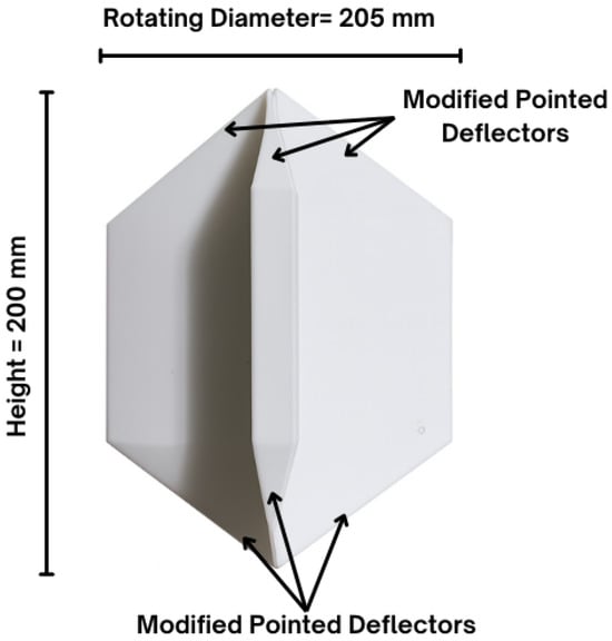
Figure 1.
Savonius wind turbine with pointed deflectors model.
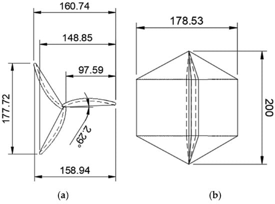
Figure 2.
Savonius wind turbine with pointed deflectors (model dimensions in mm): (a) top view; (b) side view [46].
Following the design specifications, a physical prototype was fabricated via 3D printing using and eSun ABS filament (Shenzhen Industries, Shenzhen, China). Acrylonitrile butadiene styrene (ABS) is a widely used plastic filament in 3D printing, known for its high impact resistance, hardness, and strength [47]. While ABS operates poorly in outdoor conditions, it shares similar physical material properties with acrylonitrile styrene acrylate (ASA), a derivative of ABS with enhanced weatherability and UV resistance [48]. Therefore, ABS filament was suitable for wind tunnel testing. The material properties and printing parameters are detailed in Table 1 and Table 2, respectively.

Table 1.
Material properties of eSun ABS filament [49].
Table 2.
Parameters for prototype fabrication by 3D printing.
2.2. Wind Tunnel Experimental Set-Up
The HM170 Eiffel-type (GUNT, Hamburg, Germany) wind tunnel was utilized to characterize the prototype in a controlled environment. The prototype was secured on a force sensor that measured horizontal, vertical, and twisting (torque) forces acting on the rotor. A smoke–air mixture was drawn into the chamber using a variable-speed axial fan for airflow visualization during testing. Ambient air temperature was measured at 26 °C under normal atmospheric pressure conditions during the experimental trials.
Three trials were conducted at 3 m/s, 4 m/s, and 5 m/s, respectively, to simulate the lower end of expected wind speeds in the Philippines [12]. First, the rotor was allowed to reach stable rotation in a clockwise direction, subjected only to bearing friction. Upon achieving free-spin, a dynamometer attached to the rotor shaft induced progressive brake torque on the rotor shaft until the system approached near-stall conditions. This method aimed to establish a range of quasi-steady operating points from free-spin (maximum RPM, minimal torque) to near-stall (low RPM, high torque). Rotor speed, torque, and acting forces on the rotor were measured and recorded at 5 s intervals. Diagrams showing the dimensions of the experimental set-up are shown in Figure 3 and Figure 4. The actual experimental set-up is also shown in Figure 5.
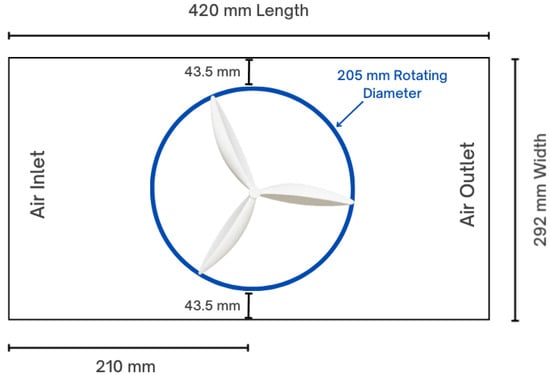
Figure 3.
Top view of wind tunnel experimental set-up.
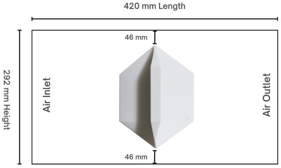
Figure 4.
Side view of wind tunnel experimental set-up.
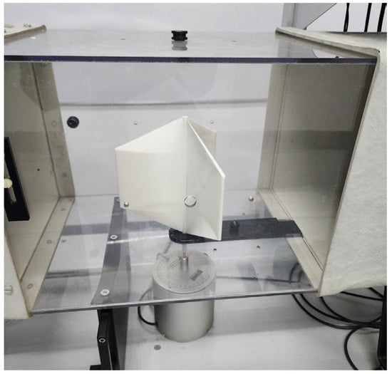
Figure 5.
Actual wind tunnel experimental set-up.
2.3. Performance Evaluation and Data Visualization
The performance and efficiency of a Savonius wind turbine design are generally evaluated based on the measured tip-speed ratio (TSR), torque coefficient (Ct), and power coefficient (Cp). The equations for each factor are shown in Equations (1)–(3), respectively.
where R is the rotor radius in m, is the angular velocity of the rotor in rad/s, and V is the measured wind speed in m/s.
where T is the measured torque in N-m, is the density of air at 1.225 kg/m3, H is the height of the rotor, D is the diameter of the rotor, and R is the radius of the rotor.
The maximum power output in watts can also be estimated using the maximum observed Cp (), as shown in Equation (4).
Due to the compact size of the wind tunnel, the measured results must be adjusted to consider the blockage ratio. This factor adjusts the experiment’s findings to project the probable performance of the turbine rotor under free-stream conditions. A high BR indicates significant interference between the walls of the wind tunnel and the flow of observed air [50]. The work of Roy et al. [51] established a comprehensive method of data modification for high BR in Eiffel-type wind tunnels to correct for wall interactions. Using this method, the blockage ratio (BR) is equal to a fourth of the frontal area of the rotor divided by the cross-sectional area of the wind tunnel test section, as shown in Equation (5).
where h and w are the height and width of the wind tunnel, respectively. The BR is also factored into the measured wind speed, the angular velocity, and torque, as shown in Equations (6)–(8) [51].
where an asterisk (*) denotes BR-adjusted values. Thus, Equations (1)–(4) are rewritten as Equations (9)–(12), respectively, to determine the adjusted Cp, Ct, TSR, and Pmax.
This yielded three datasets: unprocessed data collected directly from the experiment (No BR), and the data adjusted using the BR (With BR). The collected data were graphically visualized using RStudio (Posit, Boston, MA, USA) version 2025.12.1+563.
3. Results
3.1. Experimental Conditions
3.1.1. Prototype Characteristics
The fabricated prototype in Figure 6 weighed 731.5 g with a smooth, matte finish. No surface defects were observed after fabrication. When mounted, the turbine rotor operated with no observed oscillation or vibrational movement, indicating that the design was well-balanced and that the ABS infill was distributed evenly across the rotor.
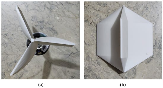
Figure 6.
Fabricated prototype: (a) top view, (b) side view.
3.1.2. Observed Blockage Ratio
The BR observed for the experimental analysis was determined as 12.02%. This value was above the generally accepted 10% threshold, which indicated that the spatial limitations of the wind tunnel caused wall interference with wake development, wind flow, and wind velocity around the rotor. The measured BR was used as a factor to project turbine rotor performance under free-stream conditions [50,51]. The raw experimental data and BR-adjusted data formed three separate datasets that are further explored in Section 3.3.
3.2. Wind Flow Visualization Analysis
The wind tunnel set-up, as shown in Figure 7 and Figure 8, shows the prototype spinning in a clockwise direction under low-wind-speed conditions. The path of the wind, visualized using smoke trails, formed a well-defined laminar flow region at the leading edge of the blade and continued to flow smoothly over the rotor’s surface. Small areas of smoke dispersion at the trailing edges of the blade exhibit signs of isolated turbulent wake formation. Minor vortex formations are also observable at the tips of the rotor during the transition period between the leaving and approaching blades. These findings indicate excellent aerodynamic performance, particularly in flow directionality, wind adherence to the blade surface, and minimization of vortex formation at the blade’s edges.
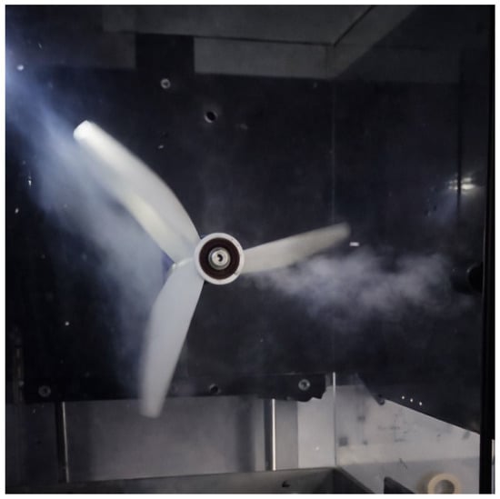
Figure 7.
Top view of rotor prototype.
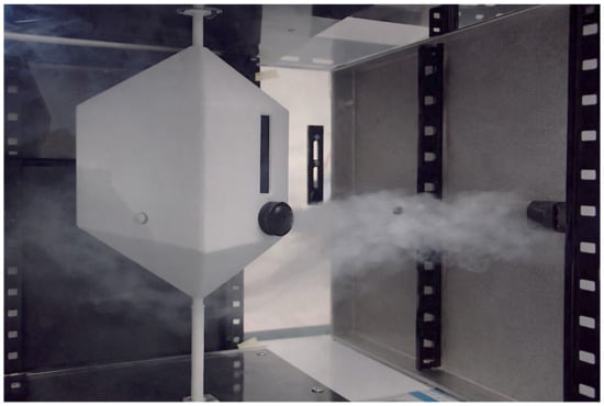
Figure 8.
Side view of rotor prototype.
3.3. Performance Analysis
The performance of a Savonius wind turbine is generally determined by its optimal TSR, where the Cp and Ct are maximized. The following section discusses the relationship of the prototype’s TSR to other observed parameters to characterize its efficiency under low-wind-speed conditions. Each figure presents both With BR and No BR data to illustrate the effect of BR on data behavior.
3.3.1. Torque Coefficient and Tip-Speed Ratio
The relationship between the Ct and TSR at a wind speed of 3 m/s, as shown in Figure 9, indicates a measurable decrease between the No BR and With BR data. The overall behavior of the curves remained generally similar between the two sets of data. The highest Ct observed for the No BR data was 0.417 with a TSR of 0.483. In comparison, the BR-adjusted data showed a lower Ct value of 0.385 with a TSR of 0.435, exhibiting an 8.31% reduction in peak Ct relative to the No BR dataset.
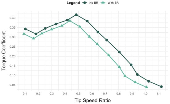
Figure 9.
The relationship between Ct and TSR at 3 m/s.
Consistent with the trend established in Figure 9, the data curvature shown in Figure 10 retains its general shape after BR incorporation at the 4 m/s wind speed condition. However, the observed curve in Figure 10 has a slightly more jagged increase in Ct as TSR increases before reaching its zenith, indicating the influence of negative torque on the system. The No BR data achieved a peak Ct of 0.405 at a TSR of 0.528, while the With BR data achieved a Ct of 0.374 at a TSR of 0.476 and a 7.41% reduction in maximum Ct.
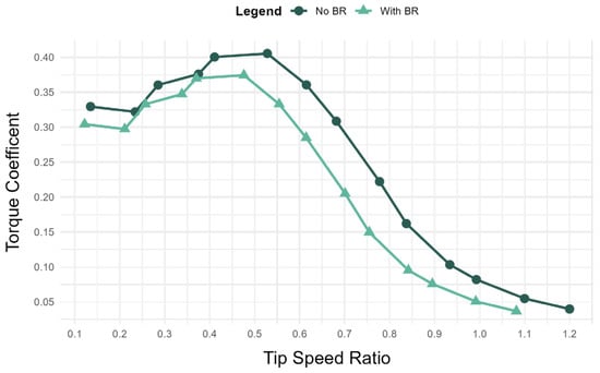
Figure 10.
The relationship between Ct and TSR at 4 m/s.
Figure 11 continues the observed data behavior established in Figure 9 and Figure 10 at the 5 m/s wind speed condition. A slight decrease in Ct at the beginning of the curve indicates notable negative torque acting on the turbine. This is overcome by a steady increase in Ct as it reaches the maximum value, followed by a steep decline, similar to the curvature of Figure 9. For Figure 11, the highest Ct observed for the No BR dataset was 0.406 at a TSR of 0.498. In contrast, the With BR dataset achieved a slightly lower peak Ct of 0.375 at a TSR of 0.449. This corresponds to an 8.26% reduction in the peak Ct between the two datasets.
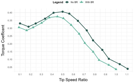
Figure 11.
The relationship between Ct and TSR at 5 m/s.
These findings indicated an optimal TSR range of 0.48 to 0.5 for the No BR data and 0.43 to 0.45 for the With BR data, which lies on the lower end of optimal TSRs for Savonius wind turbines. However, considering only BR-adjusted data, the experimental performance of the rotor achieved a satisfactory Ct of 0.385, 0.374 and 0.375 under low-wind speed-conditions for wind speeds of 3 m/s, 4 m/s and 5 m/s, respectively.
3.3.2. Power Coefficient and Tip-Speed Ratio
Figure 12 illustrates the relationship between the Cp and TSR at a wind speed of 3 m/s. The No BR dataset achieved a peak Cp of 0.217 at a TSR of 0.565. By comparison, the With BR dataset achieved a lower peak Cp of 0.181 at a TSR of 0.510, corresponding to a 19.89% reduction in the peak Cp when BR effects were considered. Unlike the relatively similar data behavior observed in Section 3.3.1, the difference in data curvature between the No BR and With BR datasets is more pronounced in Figure 12. Although both datasets exhibit a generally parabolic trend, the No BR curve peaks above the 0.2 Cp threshold and extends to higher TSR values than the With BR curve.
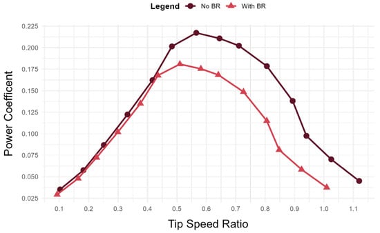
Figure 12.
The relationship between Cp and TSR at 3 m/s.
Compared to Figure 12, Figure 13 displays a more balanced bell-shaped curve relationship between Cp and TSR at the 4 m/s wind speed condition. The maximum observed Cp at this condition was 0.222 at a TSR of 0.615 for the No BR data and Cp of 0.185 at a TSR of 0.554 for the With BR data, indicating a 16.67% reduction in maximum Cp.
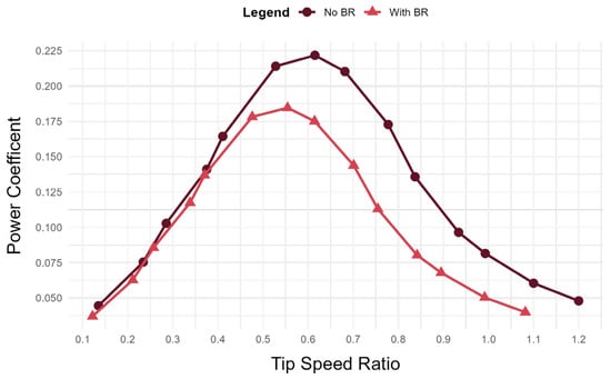
Figure 13.
The relationship between Cp and TSR at 4 m/s.
Similarly, Figure 14 shows the relationship between the Cp and TSR at a wind speed of 5 m/s, where both datasets exhibit a balanced bell-shaped parabolic curve. The No BR dataset achieved the highest Cp of 0.223 at a TSR of 0.642, whereas the With BR dataset achieved a lower peak Cp of 0.186 at a TSR of 0.579. This represents a 16.59% reduction in the measured peak Cp.
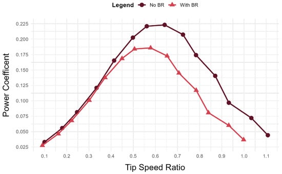
Figure 14.
The relationship between Cp and TSR at 5 m/s.
These results indicate that in terms of Cp for the specified wind velocities, the optimal operational TSR lies between 0.56 and 0.64 for the No BR dataset and in the range 0.51–0.58 for the With BR dataset. These ranges are optimal TSR values identified for the maximum Cp. Moreover, the maximum Cp values for only BR-adjusted data are 0.181, 0.185, and 0.186 for wind speeds of 3 m/s, 4 m/s and 5 m/s, respectively, which fall within the average of the expected range for Savonius wind turbines.
3.3.3. Maximum Power Output
The Pmax was derived from the maximum Cp values observed in Section 3.3.2, as shown in Table 3 below. In both datasets, the maximum power output rises notably with wind speed, indicating a direct relationship between wind velocity and extracted power. The measured power output is limited due to the compact size and scale of the prototype design, which may be deployed in groups to increase power output.
Table 3.
Maximum power output observed at each wind speed condition.
3.3.4. RPM and Tip-Speed Ratio
Figure 15, Figure 16 and Figure 17 show the relationship between the TSR and angular velocity at wind speeds of 3 m/s, 4 m/s, and 5 m/s, respectively. For both figures, the No BR dataset exhibited a near-linear relationship between TSR and angular velocity. The With BR dataset also exhibited the same behavior with a slight deviation at higher TSRs. This follows the established mathematical direct relationship between the two values with only minor deviations in slope at high TSRs.
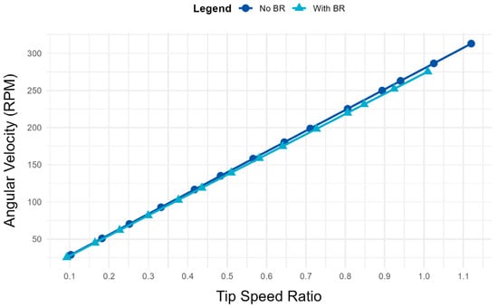
Figure 15.
The relationship between RPM and TSR at 3 m/s.
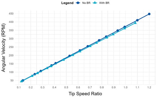
Figure 16.
The relationship between RPM and TSR at 4 m/s.
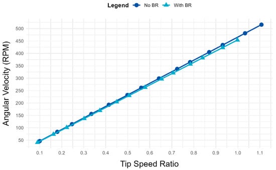
Figure 17.
The relationship between RPM and TSR at 5 m/s.
3.3.5. Torque and Tip-Speed Ratio
Figure 18 shows the relationship between the measured torque and TSR under a constant wind speed of 3 m/s. The No BR data exhibited a maximum torque of 0.0096 N-m at a TSR of 0.483, while the With BR data showed a maximum torque of 0.0085 N-m at a TSR of 0.436. This indicated a maximum torque reduction of 12.94% when BR is considered. A sharp, steady decline in torque was observed for both datasets after reaching maximum output, thus supporting the identified peaks as the optimal TSR for the 3 m/s constant wind speed condition.
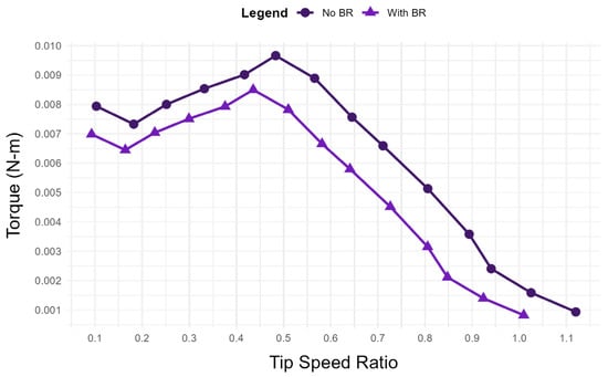
Figure 18.
The relationship between torque and TSR at 3 m/s.
Figure 19 shows a similar relationship between torque and TSR at the 4 m/s wind speed condition, where the data behaves identically to the Ct-TSR graph counterpart shown in Figure 10. This finding further supports the presence of negative torque acting on the rotor at low TSRs between 0.1 and 0.4. The highest observed torque was measured at 0.017 N-m at a TSR of 0.528 for the No BR data and 0.015 N-m at a TSR of 0.476 for the With BR data. This indicates an 11.76% decrease in maximum torque for the specified wind speed.
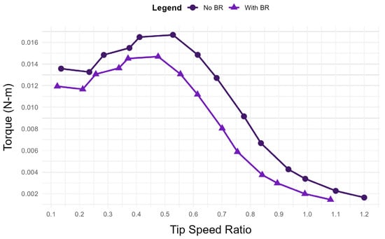
Figure 19.
The relationship between torque and TSR at 4 m/s.
Figure 20 shows the relationship between torque and TSR for the 5 m/s wind speed condition. Like Figure 19, a small decline in torque is observed after start-up due to negative torque at low TSRs. A maximum torque of 0.026 N-m at a TSR of 0.5 was observed for the No BR dataset, while the With BR dataset had a maximum torque of 0.023 N-m at a TSR of 0.449. This indicated a 13.04% decrease in maximum torque when BR is considered. Unlike Figure 14, the curves shown in Figure 15 display smoother transitions between data points as the TSR increased.
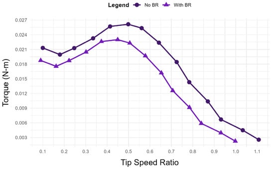
Figure 20.
The relationship between torque and TSR at 5 m/s.
4. Discussion
4.1. Wind Tunnel Testing Conditions
4.1.1. Experimental Wind Speed Conditions
The uniform wind speed conditions, namely 3, 4, and 5 m/s, were selected based on the average variation in wind speeds in the Philippines reported in the previous literature [12]. These conditions are supported by Philippine Atmospheric, Geophysical and Astronomical Services Administration (PAGASA) data indicating an annual mean wind speed of approximately 3 m/s in highly urbanized areas with dense populations and developed infrastructure, with low-lying data centers recording as low as 1 m/s wind speeds [52,53,54]. Coastal and higher-altitude urbanized environments experience notably higher wind speeds, with seasonal variability ranging up to an average of 5.5 to 6 m/s. In addition to the 3 m/s and 5 m/s wind speeds analyzed in the previous computational study, the 4 m/s condition was also evaluated as an intermediate wind speed to provide a more accurate picture of turbine performance within the specified range.
4.1.2. Adjusted Blockage Ratio
The conditions of the wind tunnel experiment sought to replicate the boundary conditions used in the previous computational study, including material properties, wind speed and direction, and rotor size [46]. The main environmental difference in the experimental set-up between the wind tunnel and CFD testing was the limited wind tunnel chamber size. The BR was an instrumental correction factor that adjusted the observed data to determine a reasonable estimation of prototype free-stream condition performance. The computed BR for the experimental set-up was measured at 12.02%, which was above the 0–10% threshold, below which BR is generally considered negligible for Eiffel-type wind tunnels [50]. When BR was considered, the data were measurably reduced, by approximately 8% in terms of Ct and 16 to 19% in terms of Cp for each wind speed, respectively. Notably, the adjusted data still retained its general shape and curve characteristics, with more pronounced deviations occurring in the Cp. This effect can be attributed to the numerical relationship between wind velocity, angular velocity, and CP, as well as the quantitative adjustments applied to these variables.
4.2. Prototype Performance
4.2.1. Prototype Quality
The 3D-printed prototype performed well in experimental testing, exhibiting negligible oscillation and vibration during operation. It required no post-printing processing and had a smooth surface finish with no visible external deformation. Such 3D-printed rotors have enormous potential in providing cheap, easily manufacturable parts for wind turbine construction and maintenance. However, 3D printing requires substantial technical knowledge to optimize printing parameters to ensure ideal performance. Variables such as print layer height, print support generation, infill density, and infill pattern can significantly impact the surface finish, weight, weight distribution, and filament consumption of any given object. A balance between economic design and performance must be reached to improve the viability of 3D-printed rotors in the future of wind energy.
4.2.2. Visual Flow Pattern Performance
The concept of flow adhesion is defined as the boundary-layer attachment that occurs at the blade or deflector surface. The loss of adhesion manifests as separation, which the classical boundary layer theory directly associates with the collapse of wall shear under adverse pressure gradients. Periodic separation and shear-layer roll-up lead to coherent vortices under Savonius operation, which convert into wake regions [55]. The wake regions, physically expressed as detached vortices, transport kinetic energy downstream, creating direct energy losses through reductions in torque and Cp. The pointed deflectors nitrated on the prototype’s rotor tips act as passive control elements to create smoother near-tip streamline turning and manage end-region pressure gradients. This, in turn, improves attachment and reduces the vortex formation at blade extremities like endplates and winglets explored in the previous literature [56].
In terms of observable flow patterns, the prototype performed exceptionally well under low wind speeds. The smoke-highlighted airflow formed clear paths of wind along the concave sides of the blades, demonstrating the design’s effectiveness at airflow–blade adhesion. These properties increase the drag force differential between the concave and convex sides of the blade, thereby improving the generated torque. While this may improve performance, it may also induce negative torque through vortex formation and recirculation of eddies at the blade edges [57]. Although no visible vortexes were observed during visual analysis of the prototype, negative torque was detected numerically, particularly at TSRs between 0.1 to 0.4. The previous CFD study that proposed the novel design detected small yet discernable vortex formations on the blade edges during cycling, which may require more sensitive experimental set-ups to detect [46]. However, the extent of the negative torque’s effects on turbine efficiency under optimal TSR operation requires further investigation. Nonetheless, the visual flow field analysis validates the findings of the previous CFD vector flow analysis study, demonstrating the capabilities of the pointed deflectors in improving rotor aerodynamics.
4.2.3. Aerodynamic Efficiency
Considering the BR-adjusted data, the prototype achieved modest maximum power coefficients of 0.181 at a TSR of 0.570, 0.185 at a TSR of 0.554, and 0.186 at a TSR of 0.579 for the 3 m/s, 4 m/s, and 5 m/s wind speed conditions, respectively. These values fall within the normative performance of an average Savonius wind turbine design, which typically falls between 0.1 and 0.25 [58,59]. The experimental data also fell short of the maximum power coefficients observed in the design’s computational simulations, which measured approximately 0.25 at a TSR range of 1.15—1.20. This indicates a 26% decrease between computational and experimental data. Most notably, the optimal operating TSR range is also drastically different. These discrepancies could be caused by prototype weight, as influenced by the infill density. Infill density is a parameter of 3D printing that dictates the percentage of material to be used for an object’s internal structure. Infill density and infill pattern are known to affect the mechanical properties, center of gravity, weight, and strength of 3D-printed objects [60]. Further experimentation could focus on the effects of these 3D-printing characteristics on the performance of wind turbine rotors.
The Ct was drastically improved from the computational simulation to 0.417 at a TSR of 0.483, 0.374 at a TSR of 0.476, and 0.375 at a TSR of 0.449 for the 3 m/s, 4 m/s, and 5 m/s wind speeds, respectively. These values fall within the generally accepted range of Ct for Savonius wind turbines and represent a vast improvement to the drastically low Ct values observed in the computational study.
The optimal operating TSR range identified for Ct is also notably close to the optimal Cp operating TSR range. Cp is generally accepted as equal to the TSR multiplied by Ct. As TSR and angular velocity increase, torque coefficient decreases due to the changing relative flow causing increased adverse drag on the returning blade, and loss mechanisms that intensify at higher speeds [61]. However, the initial increase in TSR outpaces the reduction in Ct, resulting in a transient rise in Cp; as Ct subsequently decreases at a faster rate, Cp correspondingly declines [62]. While Cp is generally always higher than Ct at any given TSR, the proximity of the optimal TSR ranges of Cp and Ct enable efficient torque and power output. This finding is a remarkable improvement to the computational results, where the optimal TSR ranges for Cp and Ct were 1.15–1.2 and 0.3738–0.3587, respectively. These developments may be attributed to the external factors acting on the rotor in real-world conditions. Factors such as bearing friction, material surface roughness, and weight distribution influence experimental systems in ways difficult to replicate through computational analysis.
4.2.4. Maximum Power Output and Potential Applications
For each wind speed, the experimental Pmax was used as the representative performance metric, reflecting a realistic achievable limit under laboratory conditions. This corresponds to operation at the optimal TSR where the Cp reaches its maximum value. Using Pmax eliminates dependence on arbitrary loading or rotational conditions and enables consistent comparison between experimental measurements and CFD predictions, as well as between different rotor configurations. This approach is standard in Savonius wind turbine performance evaluation and reflects the physically meaningful upper bound of energy extraction for a given rotor geometry and flow condition.
Considering the With BR data, the estimated Pmax of the presented prototype ranged from 0.1140 W to 0.5423 W. This range, while modest for Savonius wind turbines, is constrained by the rotor’s compact design. A wind turbine of similar capacity designed by Kishore and Priya [63] was proposed as a small portable turbine for structural monitoring devices for tall public infrastructure like bridges, highways, and household security systems. The presented prototype could serve a similar purpose, providing power to essential auxiliary services in buildings or low-power monitoring systems. The design may also be enlarged to increase capacity but will require subsequent characterization testing to fine-tune optimal operational TSRs for larger scale models.
5. Conclusions
This study presented an in-depth evaluation of a compact, 3D-printed Savonius wind turbine rotor with pointed deflectors in a wind tunnel with applied blockage ratio. Wind tunnel flow visualization demonstrated airflow concentrations along the concave sides of the blade, validating the design’s performance in the previous computational study. These findings demonstrate the design’s effectiveness in airflow–blade adhesion and improved aerodynamics under low-wind-speed conditions of 3 m/s, 4 m/s and 5 m/s.
The experimental results exhibited an increase in Ct values of 0.385, 0.374 and 0.375 and a decrease in Cp values of 0.181, 0.185, 0.186 relative to computational predictions, indicating the influence of mitigating factors such as prototype fabrication methods, tolerances, friction, and wind–wall interactions on turbine efficiency. The identified optimal TSR for a maximum Ct range of 0.43 to 0.45 and Cp range of 0.51–0.58 were observed in exceptional proximity, which enables efficient torque and power generation. These findings emphasize the importance of experimental validation when fabricating physical prototypes from computational designs. Overall, the study demonstrated the turbine’s potential for small-scale energy harvesting in low-wind-speed urban environments. Future studies may explore the effects of printing parameters on rotor performance as well as assess real-world performance and viability.
Author Contributions
Conceptualization, E.A.; methodology, E.A.; software, E.A.; validation, E.A.; formal analysis, E.A.; investigation, E.A.; resources, E.A.; data curation, E.A.; writing—original draft preparation, E.A.; writing—review and editing, E.A. and J.H.; visualization, E.A.; supervision, E.A. and J.H.; project administration, E.A. All authors have read and agreed to the published version of the manuscript.
Funding
This research received no external funding.
Data Availability Statement
Data will be made available on request.
Conflicts of Interest
The authors declare no conflicts of interest.
References
- La Viña, A.G.; Tan, J.M.; Guanzon, T.I.M.; Caleda, M.J.; Ang, L. Navigating a Trilemma: Energy Security, Equity, and Sustainability in the Philippines’ Low-Carbon Transition. Energy Res. Soc. Sci. 2018, 35, 37–47. [Google Scholar] [CrossRef]
- Manych, N.; Jakob, M. Why Coal?—The Political Economy of the Electricity Sector in the Philippines. Energy Sustain. Dev. 2021, 62, 113–125. [Google Scholar] [CrossRef]
- Philippine Department of Energy 2024 Power Statistics. 2025. Available online: https://legacy.doe.gov.ph/energy-statistics/philippine-power-statistics (accessed on 27 November 2025).
- Zubiri, J.M. Renewable Energy Act of 2008; Fourteenth Congress of The Philippines. 2008. Available online: https://ppp.worldbank.org/sites/default/files/2021-10/Philippines%20Renewable%20Energy%20Act%20of%202008.pdf (accessed on 27 November 2025).
- Dasalla, R.; Dunn, E.; Sahin, T.; Gellatly, B.; Lewis, G. Philippines Offshore Wind Supply Chain Study. 2024. Available online: https://cdn.climatepolicyradar.org/navigator/PHL/2024/the-philippines-offshore-wind-supply-chain-study_1bf27374284f98174bf568e9d309d257.pdf (accessed on 25 March 2025).
- Fritze, T.; Weigel, J.; Bertheau, P.; Dunks, C. Feasibility Study: Green Hydrogen Technology in off-Grid Areas in the Philippines; Makati City. 2024. Available online: https://reiner-lemoine-institut.de/wp-content/uploads/2024/07/Feasibility-Study_-Green-Hydrogen-Technology-in-off-grid-areas-in-the-Philippines.pdf (accessed on 6 May 2025).
- Bertheau, P.; Dionisio, J.; Jütte, C.; Aquino, C. Challenges for Implementing Renewable Energy in a Cooperative-Driven off-Grid System in the Philippines. Env. Innov. Soc. Transit. 2020, 35, 333–345. [Google Scholar] [CrossRef]
- Gacu, J.G.; Garcia, J.D.; Fetalvero, E.G.; Catajay-Mani, M.P.; Monjardin, C.E.F.; Power, C. A Comprehensive Resource Assessment for Wind Power Generation on the Rural Island of Sibuyan, Philippines. Energies 2024, 17, 2055. [Google Scholar] [CrossRef]
- Castro, M.; Ocon, J. Can Off-Grid Islands Powered by Renewable Energy Microgrids Be Operated Sustainably without Subsidies? A Techno-Economic Case Study in the Philippines. Chem. Eng. Trans. 2021, 88, 427–432. Available online: https://www.cetjournal.it/cet/21/88/071.pdf (accessed on 27 November 2025).
- Questo, L.I.; Rotor, M.A. Numerical Hydrodynamic Model of Awasan Bay, Surigao Del Norte, Philippines for Tidal Energy Resource Characterization. Discov. Ocean. 2025, 2, 55. [Google Scholar] [CrossRef]
- Eleanor, M.; Catanyag, A.; Edward, L.; Michael, T.; Abundo, L.S. Financial Analysis of a Hybrid Tidal Stream Energy System for Sustainable Island Electrification in the Philippines. Asian J. Converg. Technol. 2022, 8, 28. [Google Scholar] [CrossRef]
- Lucas, K.R.E.; Sato, T.; Ohba, M. Hourly Variation of Wind Speeds in the Philippines and Its Potential Impact on the Stability of the Power System. Energies 2021, 14, 2310. [Google Scholar] [CrossRef]
- Liu, S.; Zhang, L.; Lu, J.; Zhang, X.; Wang, K.; Gan, Z.; Liu, X.; Jing, Z.; Cui, X.; Wang, H. Advances in Urban Wind Resource Development and Wind Energy Harvesters. Renew. Sustain. Energy Rev. 2025, 207, 114943. [Google Scholar] [CrossRef]
- Filipowicz, M.; Papis-Frączek, K.; Podlasek, S. Building-Integrated Wind Turbines in Urban Environments: A Case Study From Agh’S Center of Energy. E3S Web Conf. 2025, 654, 02008. [Google Scholar] [CrossRef]
- Bošnjaković, M.; Veljić, N.; Hradovi, I. Perspectives of Building-Integrated Wind Turbines (BIWTs). Smart Cities 2025, 8, 55. [Google Scholar] [CrossRef]
- Vallejo Díaz, A.; Herrera Moya, I. Urban Wind Energy with Resilience Approach for Sustainable Cities in Tropical Regions: A Review. Renew. Sustain. Energy Rev. 2024, 199, 114525. [Google Scholar] [CrossRef]
- Chitura, A.G.; Mukumba, P.; Lethole, N. Enhancing the Performance of Savonius Wind Turbines: A Review of Advances Using Multiple Parameters. Energies 2024, 17, 3708. [Google Scholar] [CrossRef]
- Zhao, D.; Han, N. Optimizing Overall Energy Harvesting Performances of Miniature Savonius-like Wind Harvesters. Energy Convers. Manag. 2018, 178, 311–321. [Google Scholar] [CrossRef]
- Kumar, R.; Raahemifar, K.; Fung, A.S. A Critical Review of Vertical Axis Wind Turbines for Urban Applications. Renew. Sustain. Energy Rev. 2018, 89, 281–291. [Google Scholar] [CrossRef]
- Mao, Z.; Yang, G.; Zhang, T.; Tian, W. Aerodynamic Performance Analysis of a Building-Integrated Savonius Turbine. Energies 2020, 13, 2636. [Google Scholar] [CrossRef]
- Al Noman, A.; Tasneem, Z.; Sahed, M.F.; Muyeen, S.M.; Das, S.K.; Alam, F. Towards next Generation Savonius Wind Turbine: Artificial Intelligence in Blade Design Trends and Framework. Renew. Sustain. Energy Rev. 2022, 168, 112531. [Google Scholar] [CrossRef]
- Maldar, N.R.; Ng, C.Y.; Oguz, E. A Review of the Optimization Studies for Savonius Turbine Considering Hydrokinetic Applications. Energy Convers. Manag. 2020, 226, 113495. [Google Scholar] [CrossRef]
- Dewan, A.; Tomar, S.S.; Bishnoi, A.K.; Singh, T.P. Computational Fluid Dynamics and Turbulence Modelling in Various Blades of Savonius Turbines for Wind and Hydro Energy: Progress and Perspectives. Ocean Eng. 2023, 283, 115168. [Google Scholar] [CrossRef]
- Chaichana, T.; Thongdee, S. Effect of Blade Number and Angle on the Characteristics of the Savonius Type Wind Turbine. J. Phys. Conf. Ser. 2019, 1380, 012110. [Google Scholar] [CrossRef]
- Wenehenubun, F.; Saputra, A.; Sutanto, H. An Experimental Study on the Performance of Savonius Wind Turbines Related with the Number of Blades. Energy Procedia 2015, 68, 297–304. [Google Scholar] [CrossRef]
- Abdelaziz, K.R.; Nawar, M.A.A.; Ramadan, A.; Attai, Y.A.; Mohamed, M.H. Performance Investigation of a Savonius Rotor by Varying the Blade Arc Angles. Ocean Eng. 2022, 260, 112054. [Google Scholar] [CrossRef]
- Loganathan, B.; Mustary, I.; Chowdhury, H.; Alam, F. Effect of Sizing of a Savonius Type Vertical Axis Micro Wind Turbine. Energy Procedia 2017, 110, 555–560. [Google Scholar] [CrossRef]
- Akwa, J.V.; Vielmo, H.A.; Petry, A.P. A Review on the Performance of Savonius Wind Turbines. Renew. Sustain. Energy Rev. 2012, 16, 3054–3064. [Google Scholar] [CrossRef]
- Kassab, S.Z.; Chemengich, S.J.; Lotfy, E.R. The Effect of Endplate Addition on the Performance of the Savonius Wind Turbine: A 3-D Study. Proc. Inst. Mech. Eng. Part. A J. Power Energy 2022, 236, 1582–1592. [Google Scholar] [CrossRef]
- Wong, K.H.; Foo, J.S.Y.; Chong, W.T.; Mat, S.; Ng, J.H. Experimental Investigation into the Effects of Endplate Designs for a Savonius Turbine. IOP Conf. Ser. Earth Env. Sci. 2024, 1372, 012010. [Google Scholar] [CrossRef]
- Wang, X.-H.; Foo, J.S.-Y.; Fazlizan, A.; Chong, W.-T.; Wong, K.-H. Effects of Endplate Designs on the Performance of Savonius Vertical Axis Wind Turbine. Energy 2024, 310, 133205. [Google Scholar] [CrossRef]
- Farajyar, S.; Ghafoorian, F.; Mehrpooya, M.; Asadbeigi, M. CFD Investigation and Optimization on the Aerodynamic Performance of a Savonius Vertical Axis Wind Turbine and Its Installation in a Hybrid Power Supply System: A Case Study in Iran. Sustainability 2023, 15, 5318. [Google Scholar] [CrossRef]
- Saikot, M.M.H.; Rahman, M.; Hosen, M.A.; Ajwad, W.; Jamil, M.F.; Islam, M.Q. Savonius Wind Turbine Performance Comparison with One and Two Porous Deflectors: A CFD Study. Flow. Turbul. Combust. 2023, 111, 1227–1251. [Google Scholar] [CrossRef]
- Kumar, S.; Mitra, S.; Mishra, N.; Vaikuntanathan, V. Computational Fluid Dynamical Analysis of a Savonius Vertical Axis Wind Rotor Array. Phys. Fluids 2025, 37, 017163. [Google Scholar] [CrossRef]
- Tian, W.; Bian, J.; Yang, G.; Ni, X.; Mao, Z. Influence of a Passive Upstream Deflector on the Performance of the Savonius Wind Turbine. Energy Rep. 2022, 8, 7488–7499. [Google Scholar] [CrossRef]
- Ridwan; Setyawan, I.; Setiyono. Performance of Vertical Axis Savonius Wind Turbines Related to the Fin Number on the Blade. IOP Conf. Ser. Mater. Sci. Eng. 2019, 539, 012032. [Google Scholar] [CrossRef]
- Mat Yazik, M.H.; Ishak, M.H.H.; Chang, W.S.; Ismail, F.; Zawawi, M.H.; Ahmed, A.N.; Mohd Sidek, L.; Basri, H. Optimizing Structural Performance of Savonius Turbine Blades through Comparative Analysis of Mechanical Properties. Phys. Fluids 2024, 36, 087154. [Google Scholar] [CrossRef]
- Jiang, Z.; Li, H.; Yang, H.; Wu, H.; Liu, W.; Chen, Z. Review of Artificial Intelligence-Based Design Optimization of Wind Power Systems. Wind 2025, 5, 18. [Google Scholar] [CrossRef]
- Al-Shammari, S.A.; Karamallah, A.H.; Aljabair, S. Blade Shape Optimization of Savonius Wind Turbine at Low Wind Energy by Artificial Neural Network. IOP Conf. Ser. Mater. Sci. Eng. 2020, 881, 012154. [Google Scholar] [CrossRef]
- Xia, H.; Zhang, S.; Jia, R.; Qiu, H.; Xu, S. Blade Shape Optimization of Savonius Wind Turbine Using Radial Based Function Model and Marine Predator Algorithm. Energy Rep. 2022, 8, 12366–12378. [Google Scholar] [CrossRef]
- Meri Al Absi, S.; Hasan Jabbar, A.; Oudah Mezan, S.; Ahmed Al-Rawi, B.; Thajeel Al_Attabi, S. An Experimental Test of the Performance Enhancement of a Savonius Turbine by Modifying the Inner Surface of a Blade. Mater. Today Proc. 2021, 42, 2233–2240. [Google Scholar] [CrossRef]
- Zhao, D.; Han, N.; Goh, E.; Cater, J.; Reinecke, A. 3D-Printed Miniature Savonious Wind Harvester. Wind. Turbines Aerodyn. Energy Harvest. 2019, 21–165. [Google Scholar] [CrossRef]
- Velásquez, L.; Rengifo, J.; Saldarriaga, A.; Rubio-Clemente, A.; Chica, E. Geometric Optimization of Savonius Vertical-Axis Wind Turbines Using Full Factorial Design and Response Surface Methodology. Sci 2025, 7, 154. [Google Scholar] [CrossRef]
- Deda Altan, B.; Altan, G.; Kovan, V. Investigation of 3D Printed Savonius Rotor Performance. Renew. Energy 2016, 99, 584–591. [Google Scholar] [CrossRef]
- Aslan, K.; Cagan, C.; Buldum, B. Savonius Turbine Rotor Design Produced By 3d Printer. November 2017. Available online: https://www.researchgate.net/publication/325487183_Savonius_Turbine_Rotor_Design_Produced_By_3d_Printer (accessed on 23 December 2025).
- Ang, E.B.; Honra, J.P. Theoretical Aerodynamic Performance and FEA Analysis of a Novel Three-Blade Savonius Wind Turbine Blade with Pointed Deflectors. Dynamics 2025, 5, 8. [Google Scholar] [CrossRef]
- Samykano, M.; Selvamani, S.K.; Kadirgama, K.; Ngui, W.K.; Kanagaraj, G.; Sudhakar, K. Mechanical Property of FDM Printed ABS: Influence of Printing Parameters. Int. J. Adv. Manuf. Technol. 2019, 102, 2779–2796. [Google Scholar] [CrossRef]
- Sedlak, J.; Joska, Z.; Jansky, J.; Zouhar, J.; Kolomy, S.; Slany, M.; Svasta, A.; Jirousek, J. Analysis of the Mechanical Properties of 3D-Printed Plastic Samples Subjected to Selected Degradation Effects. Materials 2023, 16, 3268. [Google Scholar] [CrossRef]
- Shenzhen Esun Industrial Co., Ltd. ABS Filament Technical Data Sheet; Shenzhen Esun Industrial Co., Ltd.: Shenzhen, China, 2021. [Google Scholar]
- He, R.; Sun, H.; Gao, X.; Yang, H. Wind Tunnel Tests for Wind Turbines: A State-of-the-Art Review. Renew. Sustain. Energy Rev. 2022, 166, 112675. [Google Scholar] [CrossRef]
- Roy, S.; Saha, U.K. An Adapted Blockage Factor Correlation Approach in Wind Tunnel Experiments of a Savonius-Style Wind Turbine. Energy Convers. Manag. 2014, 86, 418–427. [Google Scholar] [CrossRef]
- PAGASA. CLIMATOLOGICAL NORMALS—SCIENCE GARDEN, QUEZON CITY. Available online: https://pubfiles.pagasa.dost.gov.ph/pagasaweb/files/cad/CLIMATOLOGICAL%20NORMALS%20(1991-2020)/SCIENCE%20GARDEN.pdf (accessed on 23 December 2025).
- PAGASA. CLIMATOLOGICAL NORMALS—NAIA (MIA), Pasay City. Available online: https://pubfiles.pagasa.dost.gov.ph/pagasaweb/files/cad/CLIMATOLOGICAL%20NORMALS%20(1991-2020)/NAIA.pdf (accessed on 23 December 2025).
- PAGASA. CLIMATOLOGICAL NORMALS—PORT AREA (MCO). Available online: https://pubfiles.pagasa.dost.gov.ph/pagasaweb/files/cad/CLIMATOLOGICAL%20NORMALS%20(1991-2020)/PORT%20AREA.pdf (accessed on 23 December 2025).
- Schlitchting, H.; Gersten, K. Boundary-Layer Theory, 8th ed.; Springer: Berlin/Heidelberg, Germany, 2003. [Google Scholar]
- Ōtomo, S.; Tasaka, Y.; Denissenko, P.; Murai, Y. On the Rotation of a Savonius Turbine at Low Reynolds Numbers Subject to Kolmogorov Cascade of Turbulence. Phys. Fluids 2024, 36, 027104. [Google Scholar] [CrossRef]
- Fatahian, E.; Ismail, F.; Ishak, M.H.H.; Chang, W.S. Aerodynamic Performance Improvement of Savonius Wind Turbine through a Passive Flow Control Method Using Grooved Surfaces on a Deflector. Ocean Eng. 2023, 284, 115282. [Google Scholar] [CrossRef]
- Rabiei, A.; Paraschivoiu, M. Performance of a Savonius Vertical Axis Wind Turbine Installed on a Forward Facing Step. Trans. Can. Soc. Mech. Eng. 2024, 48, 560–571. [Google Scholar] [CrossRef]
- Zemamou, M.; Aggour, M.; Toumi, A. Review of Savonius Wind Turbine Design and Performance. Energy Procedia 2017, 141, 383–388. [Google Scholar] [CrossRef]
- Tanveer, M.Q.; Mishra, G.; Mishra, S.; Sharma, R. Effect of Infill Pattern and Infill Density on Mechanical Behaviour of FDM 3D Printed Parts- a Current Review. Mater. Today Proc. 2022, 62, 100–108. [Google Scholar] [CrossRef]
- Dinh Le, A.; Minh, B.D.; Trinh, C.D. High Efficiency Energy Harvesting Using a Savonius Turbine with Multicurve and Auxiliary Blade. J. Fluids Eng. 2022, 144, 111207. [Google Scholar] [CrossRef]
- Hansen, M.O.L. Aerodynamics of Wind Turbines, 2nd ed.; Taylor & Francis Group: London, UK, 2008. [Google Scholar] [CrossRef]
- Anant Kishore, R.; Priya, S. Design and Experimental Verification of a High Efficiency Small Wind Energy Portable Turbine (SWEPT). J. Wind Eng. Ind. Aerodyn. 2013, 118, 12–19. [Google Scholar] [CrossRef]


Disclaimer/Publisher’s Note: The statements, opinions and data contained in all publications are solely those of the individual author(s) and contributor(s) and not of MDPI and/or the editor(s). MDPI and/or the editor(s) disclaim responsibility for any injury to people or property resulting from any ideas, methods, instructions or products referred to in the content. |
© 2025 by the authors. Licensee MDPI, Basel, Switzerland. This article is an open access article distributed under the terms and conditions of the Creative Commons Attribution (CC BY) license.