Abstract
Electromagnetic pumps are developed for industrial, medical and scientific applications, moving electrically conductive liquids and molten solder in electronics manufacturing using electromagnetism instead of mechanical parts. This study presents a comprehensive thermal analysis of an electromagnetic diaphragm pump, focusing on the influence of operating current, permanent magnet switching speed, and cooling conditions on pumping performance. The pump utilizes a flexible diaphragm embedded with a permanent neodymium magnet, which interacts with time-varying magnetic fields generated by electromagnets to drive fluid motion. Temperature monitoring is conducted using a waterproof DS18B20 sensor and an uncooled FLIR A325sc infrared camera, allowing accurate mapping of thermal distribution across the pump surface. Experimental results demonstrate that higher current and increased magnet switching speed lead to faster temperature rise, impacting the volume of fluid pumped. Incorporation of an automatic cooling fan effectively reduces coil temperature and stabilizes pump performance. Polynomial regression models describe the relationship between temperature, pumped liquid volume, and magnet switching speed, providing information to optimize pump operation and cooling strategies. The novel relationship between temperature and the volume of the pumped liquid is considered as a fourth-degree polynomial. In particular the model describes a quantitative evaluation of the effect of heating on pumping efficiency. An initial increase in temperature correlates with a higher pumped volume, but excessive heating leads to efficiency saturation or even decline. Indeed, mathematical dependencies are crucial in mechanical pump engineering for analyzing physical phenomena; this is achieved by using a mathematical equation to define how different physical variables are related to each other, enabling engineers to calculate performance and optimize the pump design.
1. Introduction
Electromagnetic pumps use electromagnets without mechanical seals for the circulation of liquid metals or aggressive liquids at high temperatures [1,2,3]. Permanent magnets are controlled and magnetized by the DC motor, the rotor has electromagnets, and their polarity is continuously reversed by the commutator and brush [4]. Magnetic fields induce motion in conducting liquids due to the electromagnetic force [5,6]. In the absence of mechanical parts, diaphragm pumps use a flexible and oscillating diaphragm to perform fluid movement, creating a pressure change during one stroke and pushing it out during the next [7,8]. The pump system can deliver the amount of fluid from one location to another with high precision [9,10]. Generally, the crucial necessities for the manufacturing of a commercial pump system are a fast response, a volumetric speed rate, and lower power consumption [11]. However, pump performance is affected by the heating mechanism due to magnetic pumping and the driving current generated within the coil in an electromagnetic pump that creates the magnetic field [12,13,14]. Therefore, the permanent magnet depends on temperature, especially in high-speed operations, and the increased Joule heat from high currents causes high electrical resistance in coils and electromagnets and their degradation, leading to the loss of overall pump performance and material deformation [15,16,17,18]. For this reason, pump cooling technology and analytical models have been developed using simulation software to create complex predictive models based on experimental results [19,20,21,22,23,24,25,26]. In this work, temperature measurements and estimation of the electromagnetic diaphragm pump system are proposed using an infrared thermal imaging camera and a waterproof temperature sensor probe as a prerequisite for the realization of a cooling system to prevent damage to the device [3,27].
For this reason, a study equation model is proposed to examine how the temperature, electrical current, flow rate of the pumped liquid and the switching frequency of the permanent magnet directly affect the pump speed and volume of liquid delivered over time in the electromagnetic pump diaphragm controlled by an Arduino platform. The relationships between the temperature, pumped liquid, and speed of permanent magnet is described by a fourth-degree polynomial equation, providing a quantitative framework to evaluate and optimize pump operation. The novelty is in the combination of a polynomial-regression mathematical model to monitor the parameters such as temperature, pumped liquid, speed of permanent magnet, and pump current, and alongside temperature monitoring, in using thermal cameras (infrared thermography) for industrial pump monitoring. Polynomial regression is often used to create empirical equations that model specific aspects of pump performance based on experimental data. In our case, a fourth-degree polynomial provides flexibility to capture the typical nonlinear shape of these curves. This is generally applicable to a narrow range of operation for a specific pump and fluid. In our case, the electromagnetic (EM) diaphragm pumps are increasingly integrated with smart monitoring systems to optimize performance through real-time thermal and operational feedback. The combination of thermal studies and performance monitoring emphasize the coupling of temperature data with flow dynamics to maintain precision flow and control by microcontrollers (e.g., Arduino-based systems) to monitor the temperature of electromagnets alongside pumping volume, and integrated sensors that capture real-time data on flow, pressure, and diaphragm wear. This allows the system to adjust the switching speed of electromagnet polarization, ensuring linear flow even as heat buildup alters material properties like copper resistivity and magnet remanence. Thermal monitoring is critical because electromagnetic efficiency depends on temperature, which can rise in electrical components, reducing power density, increasing copper losses, and directly impacting the pump’s net flow rate and pressure output.
The main contributions of this work include the following:
- Working principle, design, and testing method of the electromagnetic diaphragm pump assembled with hardware architecture [3,27].
- Detection of temperatures on the surface of the electromagnetic pump system using a thermal imaging camera to measure infrared (IR) radiation and using a sensor probe by direct physical contact.
- Polynomial regression models describe the nonlinear relationship between temperature, pumped liquid volume, and the permanent magnet switching speed.
2. Materials and Methods
Electromagnetic Pump Design and Thermal Control System
Electromagnetic diaphragm pumps can offer benefits like being more energy-efficient and quieter than air-operated pumps, requiring low maintenance for the few moving parts, and precise flow control of corrosive chemicals and hazard materials. Their realization and design can contribute to the safe handling of corrosive and abrasive chemicals substances by applying energy and are crucial for ensuring they operate efficiently, reliably, and safely for specific tasks in industries like manufacturing, water treatment, and oil and gas.
The electromagnetic diaphragm pump, developed in the Laboratory of the Department of Mechatronics at the Silesian University of Technology, Gliwice [3,27], consisted of a diaphragm, electromagnets, a permanent magnet, valves, a coil, pumping chamber, and a measurement and control system (Figure 1). Generally a diaphragm pump generates a pressure difference between the inlet (suction side) and the outlet, allowing the motion of fluids, and transfers the mechanical energy to them by increasing its pressure through the membrane to compress it. The membrane, called diaphragm, is moved by compressed air, which causes the linked diaphragms to move back and forth, creating a vacuum to draw fluid in and pressure to expel it. An electromagnetic pump uses the interaction of a magnetic field to generate a pressure gradient so as to promote fluid movement. An electromagnetic pump has no rotating parts and has a simple structure and reliable operation. The realized pump featured a circular rubber diaphragm embedded with a permanent neodymium magnet, N42, with dimension of 25 × 10 mm, which moved in response to the magnetic field generated by the electromagnets (65 × 30 core and dimension of 30 × 10 mm). This diaphragm separated the pumping chamber, where the fluid was contained and pressurized, and its motion alternately expanded and compressed the chamber, drawing in and expelling the liquid (Figure 2a). The circular diaphragm had a diameter of 65 mm and a thickness of 1.5 mm. Two inlet and outlet valves controlled the flow, allowing unidirectional movement and preventing backflow. The input and output plastic tubes, each with a diameter of 4 mm, were positioned at the top of the chamber, which had dimensions of 65 × 15 mm. The interaction between the permanent magnet and the electromagnets was driven by alternating magnetic fields generated by the coil current, producing cyclic attraction and repulsion within the chamber. A control system managed pump operation, including temperature monitoring and electromagnet actuation, through data communication based on UART (Universal Asynchronous Receiver-Transmitter), which is a hardware communication protocol used for asynchronous serial data communication between two devices, a graphical user interface, and a Nextion touch display (3rd Flr, Bld A, International Import Expo Hall, No. 663, Bulong Rd, Longgang Dist, Shenzhen, GD, China). The control cabinet integrated an Arduino Nano microcontroller (ATmega328) (Controller Nano V3.0 ATmega328P created by Atmel, Headquarters San Jose, CA, USA), a printed circuit board (PCB) as the mechanical base used to hold and connect the components of an electric circuit (EZ-Stream, China), buttons, relays (Product origin: China), a cooling fan, and a DS18B20 digital temperature sensors (product origin: China) installed on the upper surface of each radiator to monitor thermal conditions (Figure 2b).
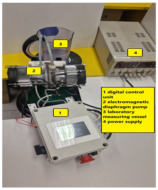
Figure 1.
The electromagnetic diaphragm pump with control unit, power source, and measuring vessel.
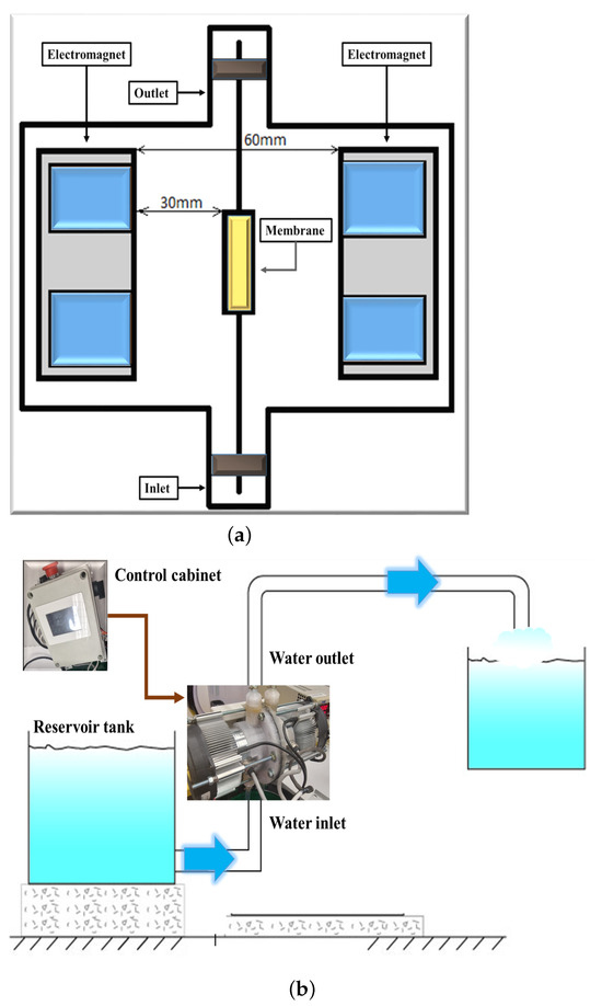
Figure 2.
(a) Illustrative design concept of the electromagnets that interact with a permanent magnet embedded in the middle of the diaphragm. As a result, the diaphragm moves toward the direction of the electromagnets. The motion of the diaphragm creates a vacuum in the pump chamber moving the fluid; (b) Schematic diagram of water pump.
Motor direction and electromagnet polarity were controlled via a BTS7960 half-bridge. For thermal regulation, the fan and DS18B20 sensor maintained safe operating temperatures. The system was powered by a 24 V DC supply. In brief, the control system was based mainly on an Arduino NANO microcontroller and for control of rotational direction of the DC motors, the BTS7960 half-bridge system with a voltage of 5 V. The electromagnets were simultaneously repelled and attracted by the permanent magnet during the power supply and connected to a half-bridge system for cyclical polarization in order to provide a sufficient fluid pumping force. The Nextion brand touch panel and the LCD display were selected to control the cabinet via UART and to read the individual parameters, respectively.
3. Measurements Tests
3.1. Description of the Measurement Stand
The electromagnetic diaphragm pump drives the fluid by utilizing the force generated from the interaction between a permanent magnet and the time-varying magnetic field produced by the current flowing through the electromagnets. Consequently, the temperature of the electromagnet steadily rises. To ensure efficient fluid transport and protect pump components from thermal damage, an investigation of the temperature field within the cooling system is required [28,29].
This study examined how temperature, electrical current, flow rate of the pumped liquid, and the switching frequency of the permanent magnet—factors that directly influence pump speed—affect the volume of liquid delivered over time. Consequently, the experimental setup included a digital Sanwa 5000 multimeter (SANWA ELECTRIC INSTRUMENT CO., LTD. Dempa Bldg, Sotokanda2-Chome Chiyoda-Ku, Tokyo, Japan), a container, a laboratory power supply, a funnel with laboratory glassware, an electromagnetic diaphragm pump, a digital control unit, and a thermal imaging camera (see Figure 1a). The coil current in the pump generates a magnetic field that interacts with the permanent magnet embedded in the diaphragm, causing it to oscillate within the electromagnetic chamber. Given an electromagnet spacing of 60 mm, the effective switching speed of the permanent magnet is approximately 1 mm/s. The switching speed indicates how quickly the permanent magnet can be moved by the electromagnet; at 1 mm/s, it would take 60 s to move the permanent magnet across the full 60 mm gap. The values of 60 mm and 1 mm/s were chosen for optimal performance based on the electromagnetic field properties and mechanical requirements. The electromagnetic spacing of 60 mm was selected to optimize the balance between signal strength and sensor detection while avoiding interference or weak signal. In particular when the electromagnets are too close, it can cause interference or a weak signal; conversely, the signal strength may become too weak for the sensor detection. The switching speed of 1 mm/s was likely chosen to ensure reliable physical and electrical switching. In particular, the switching speed is the speed at which the permanent magnet can be moved in relation to the electromagnet, while the switching time refers to the time to change the state to another. The electromagnets have variable switching times, whereas permanent magnets have constant, non-switchable magnetism. Electromagnets’ magnetic field may be turned on and off because their magnetism is regulated by an electric current. The characteristics of the electromagnets and their control circuit are determined by switching time and speed. The permanent magnet is permanently magnetized and does not require an external power source to maintain its magnetic field. Its magnetism cannot be turned on or off in the same way an electromagnet’s can, so the concept of a switching time or speed is not directly applicable to the magnet itself, although its magnetic state can be influenced by external fields. To increase the volume of pumped fluid, the diaphragm switching time was sequentially reduced by 20%, 40%, and 100%. Temperature probes were installed on the upper surface of each radiator to monitor thermal conditions (see Figure 3a). The diagram in Figure 3b shows the acquisition and control system in the electromagnetic device to produce signals such as the temperature. Both the radiator and its cooling fan were positioned adjacent to each electromagnet.
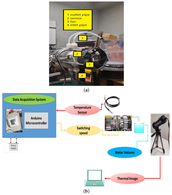
Figure 3.
(a) Electromagnetic pump setup with sensor probe for temperature monitoring; (b) Schematic diagram of temperature control system.
The sensor for measuring temperature was a DS18B20 chip encapsulated in a waterproof stainless-steel probe with a protective rubber cover and connection cable. The microcontroller received the temperature readings from the sensor and processed the information. The versatile digital temperature sensor DS18B20 communicates using a unique 1-Wire bus protocol encapsulated in a waterproof stainless-steel probe with a connection cable and rubber cover for protection. The DS18B20 is a high-precision digital temperature sensor and the DS18B20 temperature measurements typically lack explicit, custom error bars or device-specific calibration information in raw data because they are digital, factory-calibrated sensors with fixed, published accuracy specifications. The lack of cooling in ambient conditions introduces a potential self-heating effect that is not accounted for in the raw output. Therefore, the DS18B20 digital thermometer detects temperatures with 9-bit to 12-bit precision in a temperature range from −10 °C to +85 °C, with an accuracy of ±0.5 °C. This inherent accuracy range serves as the implied “error bar” for standard use. Due to its waterproof design, the sensor could be conveniently integrated with the microcontroller for reliable operation. Temperature monitoring was carried out to ensure efficient fluid transfer into the pump chamber. A reservoir containing about 12 L of water was emptied within 700 s by the electromagnetic pump with an average discharge rate of approximately 0.017 L per second (or about 17 mL per second) and with the pumping rate controlled through the switching speed of the permanent magnet. The reservoir was a 5 L wash bucket (approximately 19 L), and a plastic measuring cup with a diameter of approx. 15.5 cm and height of 21 cm was used to fill the reservoir with water.
During the experiment, the radiator operated continuously while directing the water into the chamber. In the course of operation, the electromagnets incur various electrical losses, leading to the conversion of input power into heat, which can adversely affect the magnetic components. As the system temperature rises, the current supplied at a constant voltage decreases, thereby reducing the overall magnetic field intensity. During measurements without the use of the radiator and cooling system, the coil temperature increased to 47 °C and 45 °C for the switching speeds of 20% and 40% with a supply current of 3.5 A, respectively.
At a lower current of 2 A, the corresponding temperatures were decreased, suggesting that heating is strongly dependent on operating current. Through the interaction between the electromagnet and the permanent magnet embedded in the diaphragm, the electromagnet pump works by drawing in and compressing the liquid inside the chamber, transferring energy to the fluid. At switching speeds of 20% and 40%, the maximum pumped volumes were 10.46 L and 12 L, respectively. The cooling was provided by a fan operating in the range from standstill up to 3000 rpm, controlled automatically according to the sensor temperature. Under automatic cooling, the coil temperature was kept at about 28 °C. Excess heat reduces efficiency and poses a risk of damaging the device, particularly the coil windings and insulation; therefore, heat sinks or active fans are required to stabilize operation.
3.2. Experimental Results and Analysis
The experimental data included four cases of electromagnetic pump operation: (i) supply current of 2 A at a magnet switching speed of , (ii) 2 A at , (iii) 3.5 A at , and (iv) 3.5 A at . First, the relationship between temperature and the volume of the pumped liquid (l) was considered as a fourth-degree polynomial.
where T is the temperature in degrees Celsius, and l is the volume of the liquid in liters. The fitted coefficients for the four cases considered are presented in Table 1. This table summarizes the coefficients of the fitted fourth-degree polynomial model. Their values characterize the nonlinear dependence between temperature and pumped volume for each operating condition. The coefficients allow quantitative comparison between cases and were used to evaluate how changes in current and switching speed modify the thermal response of the pump. Figure 4 and Figure 5 present plots of these dependencies. The fitted models describe the nonlinear dependency , which allows a quantitative evaluation of the effect of heating on pumping efficiency. For all cases, an initial increase in temperature correlated with a higher pumped volume, but excessive heating led to efficiency saturation or even decline.

Table 1.
Fitted coefficients of the fourth-degree polynomial for different operating conditions of the electromagnetic pump.
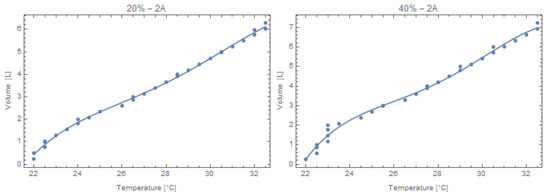
Figure 4.
Polynomial fit (4th degree) of volume vs. temperature at 2 A.
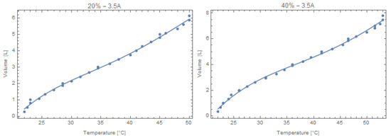
Figure 5.
Polynomial fit (4th degree) of volume vs. temperature at 3.5 A.
The temporal evolution of the system’s temperature is depicted in Figure 6 and Figure 7. It can be observed that higher switching speed (40%) and higher current (3.5 A) lead to a faster temperature rise due to increased Joule heating in the electromagnets.
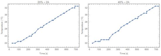
Figure 6.
Time vs. temperature for 20% and 40% switching speed at 2 A.
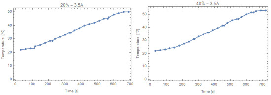
Figure 7.
Time vs. temperature for 20% and 40% switching speed at 3.5 A.
Figure 8 compares the cumulative volume of liquid pumped over time. The 40% switching speed delivers a greater volume than the 20% case for the same supply current. This effect becomes more pronounced at higher current (3.5 A).
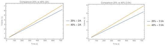
Figure 8.
Comparison of pumped liquid volume over time for different switching speeds at 2 A and 3.5 A.
3.3. Temperature Monitoring
A thermal imaging camera was used to track the temperature distribution of the electromagnetic pump system by capturing the infrared radiation emitted from the electromagnetic pump system’s surface and converting it into visual thermal images The camera was set up to record the temperature of the front surface of the pump.
The thermal imaging camera monitored both the water pumped into the system and the heat generated by the device. Then, through the use of FLIR ResearchIR Max software and an uncooled FLIR A325sc camera, detailed thermal pictures and temperature data were captured, managed, and processed using the GenICam protocol API.
The FLIR A325sc is equipped with an uncooled Vanadium Oxide (VoX) microbolometer detector, producing thermal images with a resolution of pixels at up to 60 Hz, where each pixel represents an independent temperature measurement. For accurate thermal recording during the pump operation, the camera was mounted on a tripod at a distance of 1 m from the electromagnetic pump. The emissivity was set to 0.95, while ambient temperature and relative humidity were controlled at 20 °C and 50%, respectively. In our case, a 0.95 emissivity value for water was accurate for the conditions indicated because it is a common reference value for many non-metallic, painted, or heavily oxidized surfaces, and these general values are based on prior experimental verification. Thermal imaging was performed for a pump current of 3.5 A at 40% switching speed, both with the heat sink in place and without active cooling. The infrared camera captured complete temperature maps, with warmer regions displayed in red, orange, and yellow, and cooler regions in purple and blue. During operation without cooling, the passive heat sink reached a maximum temperature of ∼50 °C (Figure 9a). Activating the automatic cooling fan, the temperature was reduced to less of 27.8 °C, which was the maximum temperature recorded by the thermal camera in that case (Figure 9b).
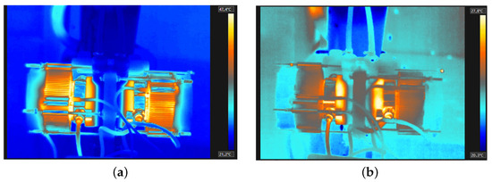
Figure 9.
Thermal images of the chamber pump: (a) without active cooling, (b) with auto-matic cooling.
The cooling system uses a fan to actively remove excess heat and maintain a target temperature around 27 °C, as observed in the temperature comparison with vs. without the cooling system for a 40 % switching speed and pump current of 3.5 A in Figure 10. In general, the thermal images obtained were in good agreement with the measurements from the temperature sensor probes, which confirms the accuracy of the thermal monitoring system.
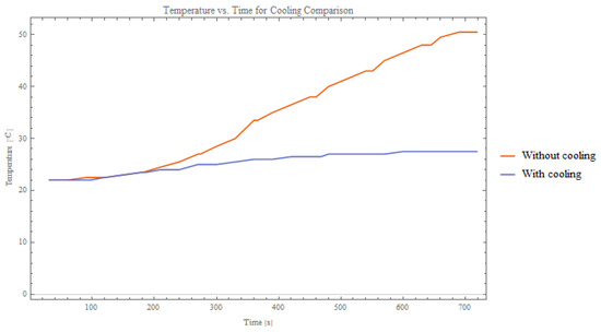
Figure 10.
Temperature comparison: with vs. without cooling system.
4. Conclusions
Electromagnetic diaphragm pumps are important due to their versatility, efficiency, and reliability and essential for applications involving liquids, fluids with solids, and viscous and corrosive chemicals. This study provided a detailed examination of the thermal behavior of an electromagnetic diaphragm pump and its influence on pumping performance. The experimental results indicated that the interaction between the permanent magnet and electromagnets produced Joule heating, which increased the coil temperature and directly affected the volume of fluid delivered. Accurate temperature mapping was achieved using both a DS18B20 sensor and an uncooled FLIR A325sc infrared camera, confirming the reliability of these measurement techniques. The observations revealed that higher supply currents and faster magnet switching speeds accelerated the temperature rise, potentially reducing pump efficiency and risking thermal damage if left uncontrolled. The introduction of an automatic cooling fan significantly reduced the coil temperature, stabilized pump operation, and prevented overheating of the electromagnet and diaphragm. The study also showed that, while the volume of pumped liquid initially increased with temperature, overheating could cause saturation or a drop in performance. Polynomial regression models successfully captured the nonlinear relationship between temperature, pumped liquid volume, and magnet switching speed, providing a quantitative framework to evaluate and optimize pump operation. In general, these findings emphasize the critical role of thermal management in diaphragm electromagnetic pumps and provide practical guidance to control temperature to maintain reliable and efficient operation.
The combination of a polynomial regression mathematical model to monitor parameters such as temperature, pumped liquid, speed of the permanent magnet, and pump current, and alongside temperature monitoring, using thermal cameras (infrared thermography) is useful for industrial pump monitoring. In this study, the electromagnetic (EM) diaphragm pump was integrated with smart monitoring systems to optimize performance through real-time thermal and operational feedback to maintain precision flow and control by microcontrollers (e.g., Arduino-based systems), and integrated sensors captured real-time data on flow, pressure, and diaphragm wear.
The limitations of this research on electromagnetic diaphragm pumps include a limited flow rate due to the small dimensions and lower power efficiency due to the supply current. The device was designed to be rated at 24 V DC with a supply current of approximately 2 A for the series connection arrangement of electromagnets, and approximately 1 A was requested by the electromagnet. However, the control electronics and heat sinks were chosen to allow the dissipation of heat energy associated with the conversion of electrical energy into energy associated with the mechanical system. The operating speed of the electromagnets was selected in the device on the basis of the switching time. The control of the supply current and switching speed was influenced by forces like resistance and friction or forces that affect the fluid’s movement associated with compression and suction of the fluid from the tank. Specifically, the increase in performance was of 17% for switching modes set to 20% and 40%.
In future work, the computational model study will investigate thermal and magnetic effects, different parameters including heat source, fluid flow, and velocity distribution to be controlled, and ensure a more stable and efficient electromagnetic diaphragm pump. Therefore, investigations will be carried out into heat management and recycling within the pump as a function of volumetric flow rate of the pumped liquid. In fact, the future system will capture the waste heat that would otherwise be lost to the environment and instead reuse it to pre-heat incoming fresh air or water in industrial applications.
Author Contributions
Conceptualization, S.S., P.K., S.C., R.B. and G.L.S.; methodology, S.S. and P.K.; software, R.B., S.S., G.C. and G.L.S.; validation and formal analysis, S.S., P.K., S.C., G.C., R.B. and G.L.S.; writing—review and editing, R.B. and G.L.S.; visualization, P.K., R.B. and G.L.S.; supervision, P.K., G.C. and G.L.S. project administration, P.K.; funding acquisition, S.C. All authors contributed equally to this work. All authors have read and agreed to the published version of the manuscript.
Funding
This research was supported by TC-SMART: “Thermomechanical characterization of shape memory alloys and possible applications in industrial and biomedical area”—PIAno di inCEntivi per la RIcerca di Ateneo 2024/2026—Linea di Intervento 1, University of Catania, and financial support by the European Regional Development Fund within the Operational Programme “Bulgarian national recovery and resilience plan”, Procedure for direct provision of grants “Establishing of a network of research higher education institutions in Bulgaria”, under the Project BG-RRP-2.004-0005 “Improving the research capacity and quality to achieve international recognition and resilience of TU-Sofia”.
Informed Consent Statement
This article does not contain any studies with human participants or animals performed by any of the authors.
Data Availability Statement
The data presented in this study are available on request from the corresponding author. The data are not publicly available due to relation to public funding specifics.
Conflicts of Interest
The authors declare no conflicts of interest.
References
- Gaile, A.; Berenis, D.; Kalvāns, M.; Milgrāvis, M.; Beinerts, T.; Grants, I.; Bojarevičs, A. Permanent Magnet Pump for Aluminum Transport in a Linear Channel. Metals 2023, 13, 1160. [Google Scholar] [CrossRef]
- Qiu, X.; Wang, Z.; Li, C.; Shen, T.; Zheng, Y.; Wang, C. Design and Optimization of a Permanent Magnet Synchronous Motor for a Two-Dimensional Piston Electro-Hydraulic Pump. Energies 2024, 17, 5379. [Google Scholar] [CrossRef]
- Sciuto, G.L.; Skupien, S.; Kowol, P.; Capizzi, G.; Coco, S. Temperature Estimation Using Infrared Thermal Imaging Camera and Temperature Sensor Probe in the Electromagnetic Diaphragm Pump. In Proceedings of the 2025 17th International Conference on Electronics, Computers and Artificial Intelligence (ECAI), Targoviste, Romania, 26–27 June 2025; IEEE: New York, NY, USA, 2025; pp. 1–6. [Google Scholar]
- Krishnan, R. Permanent Magnet Synchronous and Brushless DC Motor Drives; CRC Press: Boca Raton, FL, USA, 2017. [Google Scholar]
- Dehghan, M.; Tahmasebipour, M. Fabrication of peristaltic electromagnetic micropumps using the SLA 3D printing method from a novel magnetic nano-composite material. Sens. Actuators A Phys. 2023, 358, 114431. [Google Scholar] [CrossRef]
- Guo, K.; Jiang, J.; Zhang, D.; Meng, L.; Zhang, Y.; Fan, X.; Zhang, H. Hydrodynamic Performance Study of a Reciprocating Plate Column Dirven by Electro-permanent Magnet Technology. Machines 2024, 12, 330. [Google Scholar] [CrossRef]
- Luo, X.; Yang, L.; Cui, Y. Micropumps: Mechanisms, fabrication, and biomedical applications. Sens. Actuators A Phys. 2023, 363, 114732. [Google Scholar] [CrossRef]
- Sun, H.; Zhao, J.; Zhang, Y.; Xu, M. Flexible pump for small-scale soft robotics: Actuation, design and prospects. Measurement 2024, 237, 115299. [Google Scholar] [CrossRef]
- Zhu, J.; Zhang, H.Q. A review of experiments and modeling of gas-liquid flow in electrical submersible pumps. Energies 2018, 11, 180. [Google Scholar] [CrossRef]
- Clime, L.; Daoud, J.; Brassard, D.; Malic, L.; Geissler, M.; Veres, T. Active pumping and control of flows in centrifugal microfluidics. Microfluid. Nanofluidics 2019, 23, 29. [Google Scholar] [CrossRef]
- Gan, X.; Pei, J.; Pavesi, G.; Yuan, S.; Wang, W. Application of intelligent methods in energy efficiency enhancement of pump system: A review. Energy Rep. 2022, 8, 11592–11606. [Google Scholar] [CrossRef]
- Ley, F.; Zweibel, E.G.; Riquelme, M.; Sironi, L.; Miller, D.; Tran, A. A heating mechanism via magnetic pumping in the intracluster medium. Astrophys. J. 2023, 947, 89. [Google Scholar] [CrossRef]
- Iverson, B.D.; Garimella, S.V. Recent advances in microscale pumping technologies: A review and evaluation. Microfluid. Nanofluidics 2008, 5, 145–174. [Google Scholar] [CrossRef]
- Zhao, X.; Li, F.; Ruan, L.; Wen, J.; Zhang, Y.; Gao, R.; Zhang, F.; Zhang, K.; Wang, Y.; Yang, W. Flexible PDMS-NdFeB Composite Membrane for Haptic Force Perception. ACS Appl. Electron. Mater. 2025, 7, 1708–1717. [Google Scholar] [CrossRef]
- He, L.; Feng, Y.; Zhang, Y.; Tong, B. Methods for temperature estimation and monitoring of permanent magnet: A technology review and future trends. J. Braz. Soc. Mech. Sci. Eng. 2024, 46, 174. [Google Scholar] [CrossRef]
- Tang, H.; Di, J.; Wu, Z.; Li, W. Temperature analysis for the asymmetric six-phase permanent magnet synchronous motor in healthy and fault-tolerant modes. IEEE Trans. Ind. Electron. 2022, 70, 6482–6493. [Google Scholar] [CrossRef]
- Kwak, J.; Kim, H.R. Numerical analysis of the temperature distribution of the EM pump for the sodium thermo-hydraulic test loop of the GenIV PGSFR. Nucl. Eng. Technol. 2021, 53, 1429–1435. [Google Scholar] [CrossRef]
- Yu, Y.; Chai, F.; Pei, Y.; Zhang, X.; Lee, C.H. Comparative Thermal Analysis of Two Permanent Magnet Machines With Improved Heat Dissipation for in-Wheel Traction Application. IEEE Trans. Ind. Appl. 2025, 61, 3648–3662. [Google Scholar] [CrossRef]
- Liu, H.C. Design, Analysis, and Comparison of Electric Vehicle Electric Oil Pump Motor Rotors Using Ferrite Magnet. World Electr. Veh. J. 2025, 16, 50. [Google Scholar] [CrossRef]
- Karabulut, Y.; Ayhan, U.; Aktaş, S.; Ayaz, M.; Meşe, E. Thermal Analysis of Small-Scale Axial Flux Permanent Magnet Synchronous Motors for LVAD Systems. IEEE Trans. Ind. Appl. 2025, 61, 3701–3710. [Google Scholar] [CrossRef]
- Li, Z.; Wu, J.; Lv, C.; He, M. Analysis and experiment of internal temperature distribution and cooling performance of the liquid hydrogen pump. J. Energy Storage 2025, 111, 115365. [Google Scholar] [CrossRef]
- Qin, Y.; Li, W.T.; Yuen, C.; Tushar, W.; Saha, T.K. IIoT-enabled health monitoring for integrated heat pump system using mixture slow feature analysis. IEEE Trans. Ind. Inform. 2021, 18, 4725–4736. [Google Scholar] [CrossRef]
- Slaughter, J.; Griffith, L.; Czernuszewicz, A.; Pecharsky, V. Scalable and compact magnetocaloric heat pump technology. Appl. Energy 2025, 377, 124696. [Google Scholar] [CrossRef]
- Todorov, G.; Kralov, I.; Kamberov, K.; Sofronov, Y.; Zlatev, B. Failure mechanisms of stay vanes in a pumped hydroelectric energy storage Francis turbine unit. Aip Conf. Proc. 2025, 3274, 050001. [Google Scholar]
- Todorov, G.; Kralov, I.; Kamberov, K.; Sofronov, Y.; Zlatev, B.; Zahariev, E. Failure Modes and Effect Analysis of Turbine Units of Pumped Hydro-Energy Storage Systems. Energies 2025, 18, 1885. [Google Scholar] [CrossRef]
- Todorov, G.; Kralov, I.; Kamberov, K.; Sofronov, Y.; Zlatev, B.; Zahariev, E. Investigation and Identification of the Causes of the Unprecedented Accident at the “Chaira” Pumped Hydroelectric Energy Storage. Water 2024, 16, 3393. [Google Scholar] [CrossRef]
- Skupień, S.; Kowol, P.; Capizzi, G.; Sciuto, G.L. Control System Hardware Design, Analysis and Characterization of Electromagnetic Diaphragm Pump. Appl. Sci. 2024, 14, 8043. [Google Scholar] [CrossRef]
- Kang, T.U.; Kim, H.R. Temperature analysis of extra vessel electromagnetic pump cooling for a Micro nuclear reactor with an electric power of 20 MW. Nucl. Eng. Technol. 2024, 56, 275–282. [Google Scholar] [CrossRef]
- Brēķis, A.; Buligins, L.; Bucenieks, I.; Goldšteins, L.; Kravalis, K.; Lācis, A.; Mikanovskis, O.; Jēkabsons, N. Electromagnetic pump with rotating permanent magnets operation at low inlet pressures. Fusion Eng. Des. 2023, 194, 113919. [Google Scholar] [CrossRef]


Disclaimer/Publisher’s Note: The statements, opinions and data contained in all publications are solely those of the individual author(s) and contributor(s) and not of MDPI and/or the editor(s). MDPI and/or the editor(s) disclaim responsibility for any injury to people or property resulting from any ideas, methods, instructions or products referred to in the content. |
© 2025 by the authors. Licensee MDPI, Basel, Switzerland. This article is an open access article distributed under the terms and conditions of the Creative Commons Attribution (CC BY) license.