Abstract
Laser Wireless Power Transmission (LWPT), as a revolutionary energy supply technology, holds broad application prospects in areas such as drone endurance, space solar energy transmission, and power supply in remote regions. The core efficiency of this technology primarily depends on the energy concentration and uniformity of the light spot at the receiving end. Through systematic simulation analysis, this paper studies the spot uniformity and energy transmission efficiency of Gaussian beams, vortex beams, and flat-topped beams under different atmospheric conditions (turbulence intensity, visibility) and transmission distances. By quantitatively analyzing key indicators such as light spot non-uniformity and power density within the bucket, the advantages and disadvantages of the three beam types are comprehensively evaluated. The results indicate that the flat-topped beam is the optimal choice for short-distance laser energy transfer under favorable atmospheric conditions, while the vortex beam exhibits the best overall performance and robustness in medium and strong turbulence transmission environments. This study provides a theoretical basis for beam selection in different application scenarios.
1. Introduction
Currently, a series of experimental verifications have been conducted on laser wireless energy transmission centered around ground military bases, unmanned aerial vehicles, and space platforms. The core technological breakthroughs and basic capability verifications for the laser transmitting end and the laser receiving power conversion end have been basically completed. The core task of a laser energy transmission system is to achieve efficient and stable projection of laser energy onto photoelectric conversion devices (e.g., photovoltaic cells). In this process, the uniformity of the spot at the receiving end is crucial, mainly reflected in the following three aspects [1,2,3]:
- Conversion Efficiency Optimization: Photovoltaic cells exhibit a significant “saturation effect.” When the local light intensity exceeds a threshold, it not only triggers hotspot effects but also leads to a significant decline in photoelectric conversion efficiency. Achieving uniform illumination allows the photovoltaic cell to operate consistently within its optimal efficiency range, thereby maximizing energy conversion performance.
- System Safety Protection: Non-uniform spot distribution (particularly the inherent center-strong, edge-weak characteristic of Gaussian beams) may cause localized overheating of the receiver, potentially leading to device burnout in severe cases. Uniform light intensity distribution can effectively avoid such safety hazards.
- System Robustness Enhancement: Atmospheric turbulence causes random scintillation and spatial drift of the beam. Beam profiles with higher uniformity and stability can significantly improve the system’s resistance to atmospheric disturbances.
Traditional Laser Wireless Power Transmission (LWPT) systems commonly employ Gaussian beams due to their ease of generation and high mode purity. However, because their far-field distribution still presents a Gaussian profile, characterized by a center-strong, edge-weak intensity distribution, they severely constrain energy transmission efficiency and receiver safety. In contrast, vortex beams, with their unique annular field structure (characterized by a central dark core) and orbital angular momentum properties, theoretically can effectively avoid central overheating issues. Meanwhile, flat-topped beams (e.g., super-Gaussian beams) present a nearly flat-top intensity distribution in the near field, making them ideal optical models for achieving uniform illumination [4,5].
When a laser propagates through the atmospheric medium, it is simultaneously affected by two primary interference mechanisms: on the one hand, random fluctuations in refractive index induced by atmospheric turbulence lead to beam spreading, spatial drift, and intensity scintillation; on the other hand, absorption and scattering by aerosols cause energy attenuation [6,7,8,9]. It is noteworthy that the intensity of these interference effects changes significantly with transmission distance and variations in atmospheric environmental conditions. Therefore, systematically conducting simulation research on the transmission evolution laws of three typical beams (Gaussian, vortex, and flat-topped) under different atmospheric environmental conditions holds significant value for advancing the theoretical development and practical application of laser energy transmission technology.
2. Beam Models and Transmission Theory
This chapter focuses on the core optical foundation of laser energy transmission systems, systematically elaborating on the physical modeling methods of three typical beam types and the evolution laws of their transmission characteristics in the atmospheric environment [10,11,12,13].
2.1. Initial Beam Field Distributions
2.1.1. Gaussian Beam
As the benchmark model for traditional LWPT systems, the Gaussian beam’s intensity distribution follows a two-dimensional Gaussian function, characterized by a central peak intensity and exponentially decaying tails. The field distribution at the beam waist (z = 0) is
where is the central intensity and is the waist radius.
2.1.2. Vortex Beam
Vortex beams are constructed based on Laguerre–Gaussian or Bessel functions. The field distribution is given by Equation (2). This beam exhibits characteristic features such as an annular intensity distribution and a central dark core after propagation and evolution in space [14,15].
2.1.3. Flat-Topped Beam
Flat-topped beams are generally modeled using super-Gaussian functions or square-wave approximations, presenting a uniform top platform and steep boundary decay in intensity distribution. Here, a uniform plane wave model is adopted as follows:
2.2. Atmospheric Transmission Model
To model laser propagation in the atmosphere, two coupled interference mechanisms are primarily considered: atmospheric turbulence effects and attenuation caused by absorption and scattering [16,17].
2.2.1. Atmospheric Turbulence Model
Atmospheric turbulence can be regarded as a series of random phase screens perturbing the wavefront. According to Kolmogorov turbulence theory, the power spectral density function of its phase fluctuations is
where is the spatial wavenumber and is the atmospheric coherence length, a key parameter for measuring turbulence strength (smaller indicates stronger turbulence). By numerically simulating phase distortions caused by atmospheric turbulence, dynamic behaviors such as beam spreading, drift, and intensity scintillation can be quantitatively analyzed, revealing the influence patterns of transmission distance and turbulence intensity on spot stability. This paper constructs a phase screen model related to the refractive index structure constant, discretizes the propagation path, and inserts random phase screens at the end of each segment. Phase screens are generated by creating random phases in the frequency domain that conform to the above power spectrum, followed by an inverse Fourier transform (IFFT).
2.2.2. Atmospheric Attenuation Model
By combining Mie scattering theory, a correlation model between aerosol concentration and particle size distribution, an extinction coefficient is established. The attenuation of laser energy by molecules and aerosols in the atmosphere follows the Beer–Lambert law:
where is the attenuation coefficient, including absorption and scattering coefficients, closely related to wavelength and weather conditions. Generally, in clear weather, is small, and turbulence dominates; in hazy/foggy weather, increases significantly, and attenuation becomes the dominant factor. Specific values can be obtained through calculations using the HITRAN atmospheric database. Furthermore, simulating the interaction between photons and aerosols via the Monte Carlo method can predict the energy attenuation characteristics of the beam under different atmospheric conditions such as fog and haze, providing key parameters for system link budget estimation.
2.3. Numerical Calculation Method
The angular spectrum method is employed to accurately solve the Helmholtz equation. The calculation process for the field distribution propagating from plane to is as follows:
- Perform a two-dimensional Fourier transform (FFT) on the field distribution at to obtain the angular spectrum .
- The transfer function for angular spectrum propagation in free space is , where .
- The propagated angular spectrum is .
- Perform IFFT on to obtain the field at .
When a phase screen is present, after step 1, transform the angular spectrum back to the spatial domain, multiply by the phase screen transmission function , then perform FFT again before executing steps 2–4. Atmospheric transmission is implemented by segmentally superimposing multiple phase screens (Figure 1).
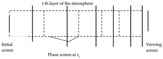
Figure 1.
Multi-phase screen method.
3. Simulation Scheme Design
3.1. Simulation Platform and Parameter Settings
This scheme employs the SeeLight laser system physical optics simulation platform, independently developed by the Institute of Software, Chinese Academy of Sciences. The platform adopts a modular architecture, fully integrating four core model libraries: geometric optics, wave optics, adaptive optics, and atmospheric optics, supporting simulation of the entire physical process from source emission to target reception. Developed based on a parallel computing architecture, the platform offers significant speed advantages when handling complex atmospheric transmission problems, reducing single simulation computation time by approximately 60% compared to traditional methods while maintaining a physical confidence level as high as 95%. Leveraging the platform’s secondary development capabilities, models for the CV uniformity parameter evaluation method and three typical atmospheric environments were added. A simulation evaluation scheme for the atmospheric transmission performance of different beam types was designed.
Aiming at the energy replenishment needs of long-endurance aerial unmanned combat platforms, key technology research and capability verification for ground-based long-distance continuous wireless energy transmission are conducted. Simulation source parameters are set as the following: operating wavelength 795 nm (near-infrared atmospheric window) continuous-wave laser, beam quality factor M2 = 5, tracking accuracy 5 μrad (RMS). Specific parameters for each beam are as follows:
- Gaussian beam parameters: Field distribution as in Equation (1), transmit power P = 100 kW, transmit aperture D = 300 mm, waist radius = 100 mm, central intensity = .
- Vortex beam parameters: Field distribution as in Equation (2), transmit power P = 100 kW, transmit aperture D = 300 mm, waist radius = 100 mm, central intensity = , topological charge l = 1.
- Flat-topped beam parameters: Field distribution as in Equation (3), transmit power P = 100 kW, transmit aperture D = 300 mm, intensity = .
Transmission scenario parameters are set as transmission distances of 5 km, 8 km, 10 km, 15 km, and 20 km (covering near-, medium-, and long-range transmission needs) and elevation angles of 0° (horizontal), 10°, 30°, 50°, 70°, and 90° (zenith). Atmospheric environmental conditions are as follows: desert environment (Condition 1, atmospheric coherence length = 13 cm at 550 nm, visibility 25 km, corresponding to weak turbulence conditions); rural environment (Condition 2, atmospheric coherence length = 9 cm at 550 nm, visibility 10 km, representing moderate turbulence intensity); urban environment (Condition 3, atmospheric coherence length = 5 cm at 550 nm, visibility 6 km, belonging to strong turbulence scenarios).
The receiving surface (target size) is set from 100 × 100 mm2 to 400 × 400 mm2 (dynamically adjusted according to transmission distance). Spatial sampling is a 256 × 256-pixel grid, satisfying the Nyquist sampling theorem. The bucket energy calculation range is the diameter enclosing 87% of the energy for Gaussian beam or 84% for flat-topped beam.
3.2. Evaluation Parameters and Simulation Process
CV (Coefficient of Variation), is defined as the ratio of the standard deviation to the mean of the intensity distribution within the receiving surface, it can be used to represent the uniformity of the beam (spot non-uniformity):
where is the intensity standard deviation and is the average intensity. A smaller CV value indicates better spot uniformity.
Power density within the bucket (I) is defined as the average power per unit area within a circular receiving region of radius a:
This parameter directly characterizes energy transmission efficiency, unit: W/cm2. For photovoltaic conversion systems, this indicator is positively correlated with photoelectric conversion efficiency.
A four-factor full factorial simulation scheme is constructed, including beam type, transmission distance, atmospheric environment, and elevation angle. The simulation execution steps are:
- Initial field setup: Generate the corresponding initial optical field complex amplitude distribution based on the beam type.
- Atmospheric transmission simulation: Solve the wave equation using the split-step Fourier algorithm with adaptive step size adjustment.
- Turbulence phase screen generation: Generate random phase screens using the power spectrum inversion method based on the Kolmogorov turbulence spectrum model.
- Attenuation effect calculation: Calculate energy attenuation caused by molecular absorption and aerosol scattering according to the Beer–Lambert law.
- Receiving surface data analysis: Extract intensity distribution, calculate evaluation parameters such as CV and power density within the bucket.
- Result storage and visualization: Save raw data and generate visualization results like spot patterns and parameter curves.
4. Simulation Results and Comparative Analysis
4.1. Free-Space Transmission Results
According to the simulation design scheme elaborated in Section 3, the transmission effects of the three beams focused over 5 km under ideal conditions of no turbulence and no attenuation were first calculated (at an elevation angle of 90 degrees). The spot non-uniformity was calculated within the full on-target diameter for each beam. Results for beam qualities of 1, 3, and 5 are shown in Table 1, Table 2, and Table 3, respectively.

Table 1.
Simulation results of free-space transmission of different beams (with beam quality of 1)—5 km.
Table 2.
Simulation results of free-space transmission of different beams (with beam quality of 3)—5 km.
Table 3.
Simulation results of free-space transmission of different beams (with beam quality of 5)—5 km.
From the simulation results, the following can be observed:
- The Gaussian beam diverges naturally with increasing distance and the central peak intensity decreases, but the Gaussian profile remains unchanged. In the far field, its beam concentration performance is optimal, resulting in the highest power density within the bucket. Under lower beam quality conditions, the uniformity of the Gaussian beam lags noticeably behind that of the flat-topped and vortex beams.
- The flat-topped beam exhibits the best uniformity in the near field. However, during propagation due to diffraction effects, its flat-top profile gradually evolves into a Gaussian-like or annular-like shape with oscillating edges. Under short-distance, turbulence-free conditions, if the receiver aperture is matched, the flat-topped beam can provide optimal uniform illumination.
- The vortex beam maintains its annular shape in the near field. In the far field, the annulus widens, and the central dark core becomes partially filled. For the same initial width, its divergence angle is larger than that of the Gaussian beam, leading to more dispersed energy and a lower power density compared to the Gaussian beam, but its spot uniformity is superior to that of the Gaussian beam.
4.2. Transmission Results at Different Distances
Based on the laser atmospheric transmission simulation calculation method described in Section 2.2, the long-exposure on-target spot characteristics were calculated for different beams at different transmission distances under three different atmospheric conditions. Results for the desert environment (Condition 1) and urban environment (Condition 3) are shown in Table 4, Table 5, Figure 2, and Figure 3 (at an elevation angle of 90 degrees), respectively (results for the rural environment are similar to the desert environment and are omitted here for brevity).
Table 4.
Simulation results for different beams and transmission distances—desert environment.
Table 5.
Simulation results for different beams and transmission distances—urban environment.
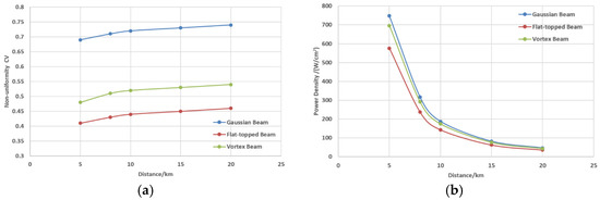
Figure 2.
Simulation results in desert environment: (a) spot non-uniformity (CV) vs. transmission distance and (b) power density on the target vs. transmission distance.
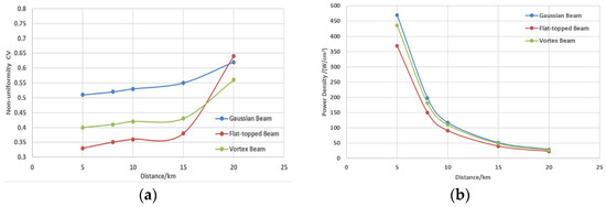
Figure 3.
Simulation results in urban environment: (a) spot non-uniformity (CV) vs. transmission distance and (b) power density on the target vs. transmission distance.
From the simulation results, the following can be observed:
- Short distance: Diffraction and turbulence effects are both weak. The flat-topped beam’s uniformity advantage is most evident, but its average power density is the lowest. The vortex beam’s annular structure remains intact. The Gaussian beam’s hotspot issue is prominent.
- Medium-to-long distance: As diffraction and turbulence cumulative effects increase for all three beams, energy decreases rapidly, power density within the bucket continuously declines, and uniformity slightly decreases. Although the Gaussian beam diverges, its energy concentration characteristic results in a relatively higher bucket power density over long distances, especially when accompanied by attenuation. The flat-topped beam’s uniformity is optimal at close range and under weak turbulence, but its advantage gradually diminishes as atmospheric turbulence intensifies. The vortex beam performs relatively stably in terms of on-target spot uniformity, particularly under long-distance and strong turbulence conditions, where its uniformity is relatively optimal.
4.3. Transmission Results Under Different Atmospheric Environments
Considering long-distance transmission scenarios, with the transmission distance set to 20 km, the long-exposure on-target spot characteristics for different beams under different atmospheric conditions were calculated. The results are shown in Table 6 (the elevation angle was set to 90 degrees).
Table 6.
Simulation results under different atmospheric conditions.
From the simulation results, the following can be observed:
- Desert environment (weak turbulence/high visibility): The Gaussian beam undergoes random drift and fragmentation due to turbulence. The central hotspot persists but becomes unstable in position, resulting in the highest power density but also the highest non-uniformity. The vortex beam’s annular structure offers some “interference resistance” to turbulence, leading to better uniformity than the Gaussian beam, but the energy is more dispersed. The flat-topped beam’s flat-top structure is disrupted by turbulence, but under weak turbulence, it still maintains the best uniformity among the three, albeit with the lowest power density.
Advantage comparison: Under weak turbulence, the Gaussian beam has the highest on-target power density but the worst uniformity; the flat-topped beam has the best uniformity but the lowest power density; the vortex beam strikes a better balance between power density and uniformity, offering good stability.
- Rural environment (moderate turbulence/medium visibility): Scattering and turbulence lead to reduced energy and enhanced spot dispersion. The Gaussian beam still has the highest power density but the worst uniformity. The flat-topped beam’s uniformity advantage is weakened. The vortex beam’s power density is intermediate, with good uniformity.
Advantage comparison: The vortex beam demonstrates advantages in stability and safety (no hotspot). The flat-topped beam’s uniformity advantage is diminished. The Gaussian beam retains a slight advantage in energy concentration but has the poorest stability.
- Urban environment (strong turbulence/poor visibility): All beams suffer severe degradation in quality, with spots splitting into multiple speckles. Long-exposure averaging leads to some improvement in uniformity for all. The Gaussian beam’s power density advantage weakens, but its uniformity improves. The flat-topped beam degrades into a speckle field, its uniformity advantage is weakened, and its power density is the worst. The vortex beam maintains good stability, having the best uniformity and the second-highest power density after the Gaussian beam.
Advantage comparison: Under strong turbulence, the vortex beam maintains good stability and robustness in both uniformity and energy concentration, making it the safest choice
4.4. Transmission Results at Different Elevation Angles
With the transmission distance fixed at 20 km and the rural environment selected, the influence of different elevation angles (from 90° to 0°) on transmission results was considered. Calculation results are shown in Table 7.
Table 7.
Simulation results under different elevation angles.
As the elevation angle decreases from 90° to 0° (turbulence increases), the power density of all three beams drops sharply. However, due to spot dispersal, uniformity improves accordingly. The Gaussian beam has the best on-target concentration and highest power density, but the worst uniformity. The flat-topped beam has good spot uniformity but the smallest power density, and its uniformity advantage disappears at horizontal transmission (strongest turbulence). The vortex beam’s performance in both spot concentration and uniformity is intermediate. As the elevation angle decreases (turbulence increases), its uniformity gradually matches that of the flat-topped beam, and its on-target power density becomes comparable to that of the Gaussian beam, making it the optimal choice.
5. Conclusions
Based on the above simulation analysis, the following conclusions can be drawn:
- The flat-topped beam is the optimal solution for short-distance laser energy transfer under favorable (or no) atmospheric conditions. It maximizes photovoltaic cell conversion efficiency and ensures safety. It is suitable for scenarios like indoor wireless power supply and close-range drone charging.
- The Gaussian beam may exhibit the highest energy transmission efficiency for receivers of limited size under long-distance, severely attenuating atmospheric conditions. This is due to its inherent propagation characteristics resulting in the highest energy concentration in the far field. The trade-off is extremely poor uniformity on the receiving surface, posing burn risks and conversion efficiency loss. It is suitable for scenarios prioritizing energy delivery, with well-designed receiver heat dissipation, or for preliminary technical verification.
- The vortex beam demonstrates the best overall performance and robustness in medium and strong turbulence transmission environments. It is less sensitive to turbulence, provides a more stable intensity distribution, and effectively prevents hotspot effects. Although its absolute energy concentration may not be the highest, its stable, hotspot-free characteristic is crucial for protecting expensive photoelectric equipment. It is suitable for medium-distance energy transfer scenarios with certain atmospheric disturbances, such as ground-to-air or air-to-air transmission.
Author Contributions
Conceptualization, F.X. and X.X.; methodology, F.X.; software, J.W.; validation, L.Z. and F.X.; formal analysis, L.Z.; investigation, L.Z.; resources, X.X.; data curation, J.W.; writing—original draft preparation, L.Z.; writing—review and editing, F.X.; visualization, L.Z.; supervision, X.X.; project administration, L.Z.; funding acquisition, F.X. All authors have read and agreed to the published version of the manuscript.
Funding
This research received no external funding.
Data Availability Statement
The data presented in this study are available on request from the corresponding author.
Conflicts of Interest
The authors declare no conflicts of interest.
Abbreviations
The following abbreviations are used in this manuscript:
| LWPT | Laser Wireless Power Transmission |
| IFFT | Inverse Fourier transform |
| FFT | Fourier transform |
| RMS | Root mean square |
References
- Oguz, O.Y. World energy outlook and state of renewable energy: 10-Year evaluation. Innov. Green Dev. 2023, 2, 100070. [Google Scholar] [CrossRef]
- Bhattacharya, M.; Churchill, S.A.; Paramati, S.R. The dynamic impact of renewable energy and institutions on economic output and CO2 emissions across regions. Renew. Energy 2017, 89, 157–167. [Google Scholar] [CrossRef]
- Hou, X.; Shi, D.; Xu, H.; Ding, S.Q. Analysis of laser wireless power supply in lunar orbit. J. Deep. Space Explor. 2024, 11, 444–452. [Google Scholar] [CrossRef]
- Cui, J.; Zhang, Z.; Deng, Y.; Ji, X.L.; Li, X.Q. Beam quality of high-power vortex beam propagating upward through turbulent atmosphere. Chin. J. Lasers 2026, 53, 3. [Google Scholar]
- Luo, Y.; Lü, B.; Tang, B.; Zhu, Y. Polarization singularities of electric and magnetic fields in Gaussian vortex beams propagating in free space. Acta Phys. Sin. 2012, 61, 134202. [Google Scholar] [CrossRef]
- Lü, B. Propagation and Control of High-Power Lasers; National Defense Industry Press: Beijing, China, 1999; pp. 236–271. [Google Scholar]
- Rice, C.A.; Pitz, G.A.; Guy, M.R.; Perram, G.P. Open-Path Atmospheric Transmission of Diode-Pumped Alkali Lasers in Maritime and Desert Environments. Appl. Spectrosc. 2023, 77, 335–349. [Google Scholar] [CrossRef] [PubMed]
- Masamori, E.; Hiroki, N.; Fumio, W. Analytical model of a diode-pumped cesium laser for investigation of upper-state mixing and quenching reactions. Opt. Express 2023, 31, 15423–15437. [Google Scholar] [CrossRef]
- Zhang, L.; Xi, F.; Liu, Q.; Xu, X. Atmospheric transmission calculation of diode-pumped alkali laser energy transfer. Microw. Opt. Technol. Lett. 2023, 66, e33935. [Google Scholar] [CrossRef]
- Coles, W.A.; Filice, J.P.; Frehlich, R.G.; Yadlowsky, M. Simulation of wave propagation in three-dimensional random media. Appl. Opt. 1995, 34, 2089–2101. [Google Scholar] [CrossRef] [PubMed]
- Zhang, H. Fundamentals of Atmospheric Turbulence; Peking University Press: Beijing, China, 2014. [Google Scholar]
- Andrews, L.C.; Phillips, R.L. Laser Beam Propagation through Random Media, 2nd ed.; SPIE Press: Bellingham, WA, USA, 2005. [Google Scholar]
- Peng, J.; Zhao, Y. Research on laser atmospheric transmission problems. J. Natl. Univ. Def. Technol. 1990, 12, 91–96. Available online: http://journal.nudt.edu.cn/gfkjdxxb/article/abstract/199001016 (accessed on 14 January 2026).
- Ding, P.; Pu, J. Spot analysis of partially coherent vortex beams during propagation. Acta Phys. Sin. 2012, 61, 174201. [Google Scholar] [CrossRef]
- Liao, C.; Jiang, F.; Sun, X.; Wang, C.; Liu, X.; Yin, S.Y. Study on 4.6 km real atmospheric transmission of Laguerre-Gaussian beam and sharp vortex beam. Laser Optoelectron. Prog. 2026, 63, 7. [Google Scholar]
- Cao, Z.; Yao, H.; Zhang, Y.; Zhang, T.; Wang, W.; Jiang, K.; Liu, J.; Dong, Q.; Hao, Q.; Jiang, H. Research progress in atmospheric turbulence image simulation and correction methods (Invited). Laser Optoelectron. Prog. 2025, 62, 2200001. [Google Scholar] [CrossRef]
- Zheng, J.; Wang, J.; He, A.; Zhang, W.K. Research on atmospheric turbulence simulation technology based on laser near-field wavefront modulation. Electro-Opt. Technol. Appl. 2025, 40, 14–20. Available online: https://www.opticsjournal.net/Articles/OJbb7d9fa706d8fcc8/Abstract (accessed on 14 January 2026).


Disclaimer/Publisher’s Note: The statements, opinions and data contained in all publications are solely those of the individual author(s) and contributor(s) and not of MDPI and/or the editor(s). MDPI and/or the editor(s) disclaim responsibility for any injury to people or property resulting from any ideas, methods, instructions or products referred to in the content. |
© 2026 by the authors. Licensee MDPI, Basel, Switzerland. This article is an open access article distributed under the terms and conditions of the Creative Commons Attribution (CC BY) license.