Abstract
Apodization is a well-known method designed to control the propagation of light in photonic crystals (PCs) and has a variety of applications. Apodization involves modulating the depth of refractive index variation in PCs. In this work, we considered harmonic PCs with different forms of linear apodization. We investigated the characteristics of reflection, absorption, photonic density of states (PDOS), and light energy density spectra in the PC. For the first time, it was shown that apodization significantly reduces the PDOSs at the first edge modes, while its influence on higher-order edge modes is considerably weaker. Depending on the apodization profile, the spectral density of integral absorption can either substantially increase or decrease, and, moreover, in large intervals. We also studied the evolution of light localization in the PC, both in the presence and in the absence of apodization. One of the central and most significant claims in our paper is the demonstration of a divergence between integral absorption and total localized light energy. Our results demonstrate that apodization leads to a reduction in the total integral light energy localized within the PC layer.
1. Introduction
Apodized one-dimensional photonic crystals (PCs) represent a promising class of photonic structures in which the modulation depth of the refractive index varies along the crystal axis [1,2]. This enables efficient control over the propagation, reflection, transmission, absorption, and localization of electromagnetic waves, opening up new possibilities for light manipulation and the development of optical devices. One of the key advantages of apodization is the suppression of undesirable side oscillations (or sidelobes) near the edges of the photonic bandgap (PBG), which arise due to sharp boundaries and interference effects in conventional periodic structures [3,4,5,6,7,8,9,10,11,12,13,14,15,16,17,18,19,20,21,22,23,24,25]. These sidelobes can lead to noise, reduced contrast, and instability in optical systems [15,16]. In contrast, apodized structures exhibit smoother and more predictable spectral characteristics, making them particularly valuable for applications in high-precision optical filters, resonators, and sensors [17,18,19].
It should be noted that studies on apodized one-dimensional PCs typically consider two types of crystals: layered and harmonic PCs. The latter belongs to the class of photonic crystals with a continuous harmonic refractive index modulation and exhibits a number of unique optical properties due to the absence of sharp interfaces between layers. Such structures enable effective control of light propagation while minimizing scattering and parasitic interference effects typical of discrete layered systems. One of the most interesting features of harmonic PCs is the dependence of the Brewster angle on the order of the PBG. In conventional periodic structures, the Brewster angle—the angle at which the reflectance for p-polarized light vanishes—is determined solely by the average refractive indices and does not depend on the bandgap order. However, in PCs with smoothly varying refractive index, such as those with a sinusoidal profile, a shift in the Brewster angle toward smaller values is observed as the PBG order increases. This phenomenon is associated with changes in the effective optical thickness and dispersion characteristics of the structure for different harmonics of the electromagnetic field [16].
Recently, particular attention has been paid to the effects of electromagnetic field localization, absorption, and the formation of an inhomogeneous photonic density of states (PDOS) in photonic structures. In apodized harmonic PCs, the smooth variation in the refractive index reduces scattering and suppresses unwanted resonances. This makes apodized harmonic PCs promising for applications in optical buffers, time-delay devices, optical memory, selective filters, and spectral analysis systems.
In this work, we investigate, theoretically, the optical properties of one-dimensional apodized harmonic photonic crystals with a linearly varying modulation depth of the dielectric permittivity. For the first time, we investigated the spatial localization of the electromagnetic field, spectral features of the photonic density of states, and asymmetric absorption effects. The apodized structure, which exhibits different absorption depending on the direction of incident laser radiation [16], resembles the behavior of an optical diode [24,25]. This absorption asymmetry, arising from the breaking of spatial symmetry in light localization within the structure, opens new avenues for developing optical devices without the need for magnetic fields or nonlinear media. The obtained results deepen the understanding of the role of apodization in light control and demonstrate the significant potential of such crystals for applications in modern photonic technologies, including integrated photonics, optical sensors, and information processing devices.
2. Theoretical Background
Let us consider the propagation of light through a planar one-dimensional PC (Figure 1). We will consider the light normal incidence case. We will assume that the PC layer borders on both sides with isotropic half-spaces with the same refractive index .
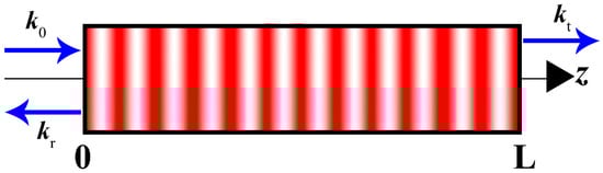
Figure 1.
The geometry of the problem. The periodic alternation of red and white areas indicates a harmonic change in the permittivity of the PC along the z axis. , , and are the wave vectors of the incident, reflected, and transmitted waves, respectively. L is PC thickness.
We will consider the PC with a dielectric permittivity and magnetic permeability of the form:
where is the value of the dielectric permittivity in the absence of modulation, is the spatial period of the PC, is the depth of modulation, is the coordinate inside the 1D PC directed along the PC optical axis.
We will consider two types of apodized PCs. The first-type corresponds to an apodized structure, with the following law of apodization:
and the second type is defined by
Here is the thickness of the PC. In the first case, along the direction of light propagation, the modulation depth decreases linearly from the value at the input surface to the value at the output surface, while in the second case, it increases linearly from at the input surface to at the output surface (Figure 2).
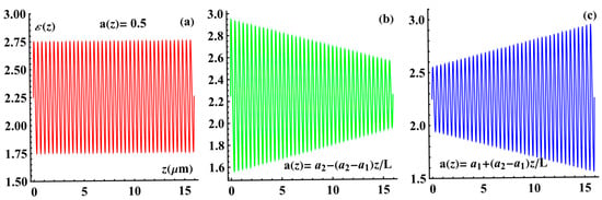
Figure 2.
Dependence of the PC dielectric permittivity on . (a) The non-apodized PC with , (b) the first-type apodized PC, and (c) the second-type apodized PC. The parameters are as follows: , , , , and .
In Figure 2, the red line represents the non-apodized PC, the green line corresponds to the first-type apodized PC, and finally, the blue line corresponds to the second-type apodized PC.
Below, we will compare the results for apodized PCs with those for a non-apodized PC with .
To study such structures, we have chosen the mathematical method developed in references [26,27,28]. We will assume that the plane of incidence coincides with the (, ) plane, and we will consider the light normal incidence case, and the layer boundaries coincide with the (, ) plane. The amplitudes for the electric field of the incident, reflected, and transmitted plane waves will be denoted by , and , respectively.
The complex amplitudes of transmission and reflection can be written in the following form:
and the corresponding transmission and reflection coefficients are defined as
In accordance with the theory, developed in [26,27,28], the amplitude coefficients and are expressed as
and the functions and are solutions to the following differential equations:
with boundary conditions .
Here, , , is the wavelength of the incident light; and are the dielectric and magnetic permeabilities of the medium bordering on both sides of the inhomogeneous medium layer. Here, the indices and denote the functions calculated before and after the inversion, and in system (7).
Absorption is calculated using the formula .
There are several methods for calculating the photonic density of states (PDOS), which are described and compared in detail in references [28,29]. The most general method for computing the PDOS of a structure is the weighted averaging of the local density of states, which, in turn, is determined using Green’s function. However, in many cases, it is more convenient to calculate the PDOS via the so-called phase time (or Wigner delay time , which requires only the spectral dependence of the transmission coefficient :
where is the Wigner delay time, and is the angular frequency of light. For convenience, the figures in this work will present the relative quantity PDOS, , where is the PDOS of the isotropic media surrounding the PC, and c is the speed of light in a vacuum.
To calculate the field distribution, we use the following formula [16]:
The light energy density in the PC will be calculated by the following formula [28]:
We will assume that , that is, the PC is in a vacuum.
In conclusion of this section, we remark that all programs were compiled in Visual Basic (the system of the differential equation, Equation (7), was solved by the Runge–Kutta method) and debugged by the authors, and the graphs were built using the Excel (Microsoft 365) and MATLAB (R2019(b)) software.
3. Results and Discussion
Firstly, we will consider reflection, PDOS, and absorption peculiarities of apodized PCs. Figure 3 shows the reflection spectra corresponding to the non-apodized PC (red curve), the first-type apodized PC (green line), and the second-type apodized PC (blue line). At first glance, it seems that the first-type apodized PC is equivalent to a second-type apodized PC, assuming that light is incident from the opposite side of the PC. However, of course, this is not the case. In the absence of absorption, apodization introduces no asymmetry in either reflection or transmission—that is, the reflection and transmission spectra for mutually opposite directions of light incidence on the PC layer are identical. Indeed, replacing with in Equations (1) and (2) (or (1) and (3))—which is equivalent to reversing the direction of light incidence—does not alter the reflection and transmission spectra. This is also confirmed directly by our numerical simulations.
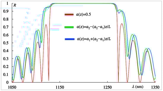
Figure 3.
Reflection spectra corresponding to the non-apodized PC (red curve), the first-type apodized PC (green line), and the second-type apodized PC (blue line). The parameters are the same as in Figure 2.
The situation is different when absorption is present. As demonstrated in [16], due to the asymmetry in the light localization in apodized (as well as chirped) PCs, absorption and reflection asymmetry arises—that is, the reflection and absorption spectra are no longer identical for opposite directions of incidence.
However, as seen in Figure 2, even in the absence of absorption, the reflection spectra of a PC layer with the first-type apodization differ from those with the second-type apodization.
Nevertheless, it should be noted that there may be specific cases when the reflection spectra (as well as the transmission and absorption spectra) for two types of linear apodization with apodization laws (Equation (2)) and (Equation (3)) coincide. Indeed, if we choose a PC with thickness (where is an integer) and in Equation (1) instead of an odd function of z we take an even function of (for instance, , then, in the case of linear apodization and zero absorption, the spectra of a PC with the first type of apodization become identical to those with the second type of apodization. This is due to the fact that under such conditions, the rotation of the PC layer around the axis by 180 degrees does not change the symmetry of the problem, while in the case of an odd function at such a rotation, we do not obtain the same system. This is also confirmed directly by our numerical simulations.
Figure 4 shows the spectra of the PDOS corresponding to the non-apodized PC (red curve), the first-type apodized PC (green line), and the second-type apodized PC (blue line). As can be seen in Figure 4, and as is well known, in the absence of apodization, exhibits two main maxima near the edges of the photonic bandgap (PBG), a maximum associated with the short-wavelength edge mode and another with the long-wavelength edge mode. This figure clearly shows that apodization significantly reduces both the short-wavelength and long-wavelength peak values of the PDOSs. Consequently, apodization substantially increases the lasing threshold for the corresponding edge modes, since the lasing threshold is inversely proportional to the PDOS [30]. The effect of apodization on the PDOS values at other edge modes is negligible.
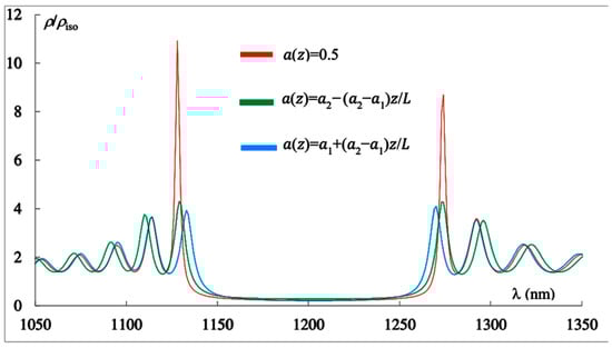
Figure 4.
The PDOS spectra corresponding to the non-apodized PC (red curve), the first-type apodized PC (green line), and the second-type apodized PC (blue line). The parameters are the same as in Figure 2.
These peculiarities have their explanation. The periodicity of the structure leads to a redistribution of photonic states in the spectrum; they migrate from the band gap region to edge modes. Violation of the periodicity leads to a decrease in the redistribution, which is reflected in an increase in the PDOS within the photonic band gap and a decrease in the edge modes. The amplitude of the nearest edge modes increases more rapidly with increasing periodicity of the structure (the number of periods), whereas when the periodicity is violated (apodization), they decrease most rapidly.
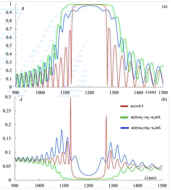
We now turn to a detailed investigation of the influence of losses on the reflection, transmission, and absorption spectra. Figure 5 shows the reflection spectra (a), transmission spectra (b), and absorption spectra (c) corresponding to the non-apodized PC (red curve), the first-type apodized PC (green line), and the second-type apodized PC (blue line) in the presence of absorption, with .
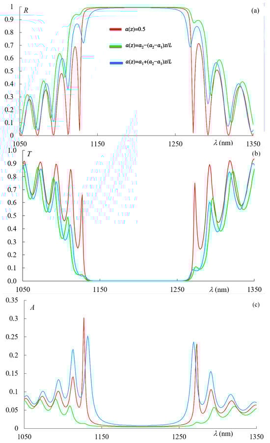
Figure 5.
Reflection spectra (a), transmission spectra (b), and absorption spectra (c) corresponding to the non-apodized PC (red curve), the first-type apodized PC (green line), and the second-type apodized PC (blue line) in the presence of absorption, with . The other parameters are the same as in Figure 2.
As can be seen from Figure 5a, in the case of the second-type apodization, an effective broadening of the photonic bandgap (PBG) occurs, whereas for the first-type apodization, an effective narrowing of the PBG width is observed. This is natural, since in the case of the first-type apodization, a high refractive index contrast exists at the input of the PC, leading to a wider PBG, while for the second-type apodization, the contrast at the input is small, resulting in a reduced PBG width.
Figure 5b demonstrates the strong influence of apodization on absorption. The absorption is also significantly affected by the shape of the apodization type. This is also physically intuitive: for the second-type apodization, light penetrates deeply into the structure, leading to a substantial increase in total (integral) absorption. In contrast, for the first-type apodization, light is strongly reflected by the first few layers of the PC due to the high index contrast at the front, resulting in a significant reduction in the total absorption.
Next, we investigated the influence of apodization, as well as periodic modulation in general, on the spectral density of integral absorption. The spectral density of integral absorption was calculated using the following formula:
with and . For , we obtained the following results: for the PC without apodization; for the PC with the first-type apodization; for the PC with the second-type apodization; and finally, for a homogeneous isotropic layer with parameters , and These parameters are the parameters of the PC without the modulation of dielectric permittivity. Thus, the results presented lead to the following conclusions:
- (1)
- Periodic modulation of the medium dielectric permittivity leads to a significant reduction in the spectral density of integral absorption in the spectral region including PBG.
- (2)
- In the case of apodization, depending on the apodization profile, it can either substantially increase (for the second-type apodization) or significantly decrease (for the first-type apodization) the spectral density of integral absorption. This, in its turn, is due to the peculiarities of light localization in the structures of the corresponding PCs and the peculiarities of their reflectivity (see below).
Now, in particular, to understand a number of properties of absorption and PDOS of apodized photonics crystals, we are investigating peculiarities of light localization. This is also important for a complete presentation of the results on apodized PCs. Figure 6 shows the evolution of the light intensity inside the PC layer when the coordinate changes in the case of the absence of apodization. As can be seen from this figure, a strong light trapping takes place at edge modes, while in the PBG, evanescent waves arise [28].
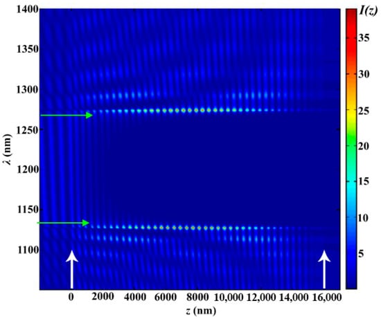
Figure 6.
The evolution of the spectrum when the coordinate changes for the non-apodized PC. The other parameters are the same as in Figure 2. White arrows show the PC layer’s left and right boundaries. Green arrows highlight the wavelength region where the PBG is observed and where the waves in the medium are evanescent.
Figure 7 shows the same as in Figure 6 evolutions of the light intensity inside the PC layer when the coordinate changes in the case of the second-type apodization (a) and in the case of the first-type apodization (b).
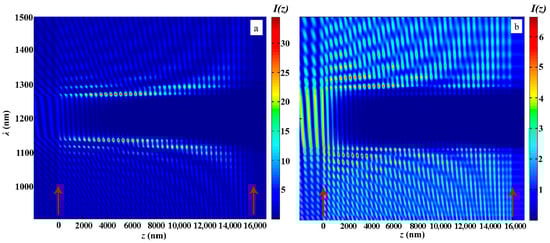
Figure 7.
The evolution of the light intensity inside the PC layer when the coordinate changes in the case of the second-type apodization (a) and in the case of the first-type apodization (b). The other parameters are the same as in Figure 2. Red arrows show the PC layer’s left and right boundaries.
Figure 8 shows the spectra of the light energy density in the PC for PC with ideal periodical structure (red line), for the PCs with the first-type apodization (green line), and for the one with the second-type apodization (blue line).
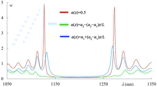
Figure 8.
The spectra of the light energy density in the PC for PC with ideal periodical structure (red line), for the PC with the first-type apodization (green line), and for the one with the second-type apodization (blue line). The other parameters are the same as in Figure 2.
Let us note that the features of the light localization shown in Figure 7 and Figure 8 and the reflection features shown in Figure 5 explain the above-presented features of the spectral density of integrated absorption.
Then we calculated the total, localized in the PC, in the finite spectral range from to light energy density F, using the following expression:
with and . As our calculations show, we have the following values of : for the PC with an ideal periodical structure, we have , for the PC with the second type of apodization, we have , and finally, for the one with the first type of apodization, we have .
The results presented lead to the following conclusions:
- (1)
- Apodization leads to a reduction in the total light energy density localized within the PC layer over a finite spectral range.
- (2)
- The behavior of the total light energy density localized within the PC layer over a finite spectral range differs from that of the spectral density of integral absorption. In particular, while apodization always leads to a reduction in , the spectral density of integral absorption can either increase or decrease depending on the apodization profile. In the case of apodization, as expected, the values of depend on the apodization profile, too. In the case of the second-type apodization, the value is more than twice that in the case of first-type apodization.
We now turn to the analysis of the results for larger slopes of the apodization function for a more complete understanding of the influence of apodization on the optical properties of PC. We consider the case where , and Figure 9 shows the reflection spectra (a) and absorption spectra (b) for these parameters, corresponding to the three cases of the dependence presented in Figure 2 in the presence of absorption with .
In this case, for and nm, the values of are as follows: for the PC without apodization; for the PC with the second-type apodization; and for the PC with the first-type apodization.
Figure 10 shows the same as in Figure 7 evolutions of the light intensity inside the PC layer when the coordinate z changes in the case of the second-type apodization (a) and in the case of the first-type apodization (b) at and .
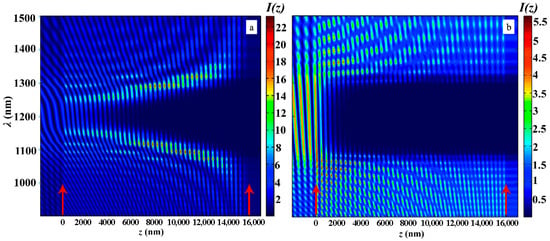
Figure 10.
The evolution of the light intensity inside the PC layer when the coordinate changes in the case of the second-type apodization (a) and in the case of the first-type apodization (b) at , and . The other parameters are the same as in Figure 2. Red arrows show the PC layer’s left and right boundaries.
As follows from the presented results, the increase in the slope of the apodization function brings in a decrease in the light trapping by the PC structure.
Figure 11 shows the spectra of the light energy density for PC with ideal periodical structure (red line), for the PCs with the first-type apodization (green line), and for the one with the second-type apodization (blue line) at and .
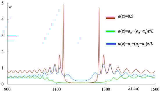
Figure 11.
The spectra of the light energy density in the PC for PCs with ideal periodical structure (red line), for the PCs with the first-type apodization (green line), and for the second-type apodization (blue line) at and . The other parameters are the same as in Figure 1.
As our calculations show, at and we have the following values of : for the PC with ideal periodical structure, we have ; for the PC with the second-type apodization, we have ; and finally, for the one with the first-type apodization, we have .
Next, to demonstrate the possibilities of apodization to tune the PC photonic properties, by expressing as and as we investigated the influence of varying on the reflection, absorption, and PDOSs spectra. Figure 12, Figure 13 and Figure 14 shows the evolution of the reflection, absorption and PDOS spectra, correspondingly, for the second-type apodization (a) and first-type apodization (b) as the parameter is varied.
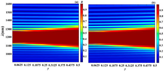
Figure 12.
Evolution of reflection spectra for second-type apodization (a) and for first-type apodization (b) as the parameter is varied. Here, and . The other parameters are the same as in Figure 2.
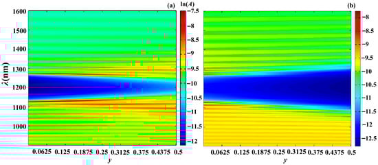
Figure 13.
Evolution of spectra for second-type apodization (a) and for first-type apodization (b) as the parameter is varied. Here, and . The other parameters are the same as in Figure 2.
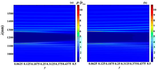
Figure 14.
Evolution of spectra for second-type apodization (a) and for first-type apodization (b) as the parameter is varied. Here, and . The other parameters are the same as in Figure 2.
As follows from the presented results, by changing the apodization parameters, we can tune the reflection, absorption, PDOS, and other photonic parameters of PC, and, moreover, within a wide range. In particular, increasing the parameter leads
- To an increase in the width of the PBG, with both types of apodization;
- To a significant increase in absorption with the second type of apodization and a significant decrease with the first type of apodization;
- To a significant decrease in the PDOS at the edge modes, with both types of apodization.
4. Conclusions
In conclusion, we have investigated the features of reflection, absorption, PDOSs, and light localization in harmonic apodized photonic crystals. We considered two types of linear apodization: and , analyzing their effects for different slopes of the linear apodization profile.
Apodization significantly reduces the PDOSs at the first edge modes, while its influence on higher-order edge modes is considerably weaker. Depending on the apodization profile, the spectral density of integral absorption can either substantially increase or decrease. We have shown that apodization leads to a reduction in the total light energy integral over the PC layer within a finite spectral range, and that the behavior of integral absorption does not follow the same trends as light localization. As mentioned above, this is due to the peculiarities of light localization and reflection in apodized crystals. Moreover, not all absorption features can be explained solely by the spatial localization of light in the photonic crystal.
By expressing and , we also studied the influence of varying the parameter y on the reflection, absorption, and PDOS spectra. In such a way, we demonstrate the possibility of obtaining a tunable photonic device using apodization.
We note that our results may pave the way for new applications in photonic devices, solar cells, sensors, and communication technologies, one-sided reflectors and absorbers, tunable PBG systems, etc., where precise control over light propagation is crucial. These findings not only deepen the fundamental understanding of photonic materials but also open up new avenues for the development of next-generation photonic systems.
Author Contributions
Conceptualization: I.M.E., S.S.G. and A.H.G.; formal analysis: I.M.E.; software: K.C.S. and I.M.E.; writing—original draft preparation: I.M.E. and A.H.G.; writing—review and editing: K.C.S. and S.S.G.; project administration: A.H.G. All authors have read and agreed to the published version of the manuscript.
Funding
The study was supported by the Russian Ministry of Science and Higher Education under the state assignment (Project FZNS-2023-0012).
Institutional Review Board Statement
Not applicable.
Informed Consent Statement
Not applicable.
Data Availability Statement
Data are contained within the article.
Acknowledgments
The authors express their sincere gratitude to the anonymous reviewers for their comments and valuable suggestions.
Conflicts of Interest
The authors declare no conflicts of interest.
References
- Yablonovitch, E. Inhibited spontaneous emission in solid-state physics and electronics. Phys. Rev. Lett. 1987, 58, 2059. [Google Scholar] [CrossRef]
- John, S. Strong localization of photons in certain disordered dielectric superlattices. Phys. Rev. Lett. 1987, 58, 2486. [Google Scholar] [CrossRef]
- Yokoi, N.; Fujisawa, T.; Saitoh, K.; Koshiba, M. Apodized photonic crystal waveguide gratings. Opt. Express 2006, 14, 4459–4468. [Google Scholar] [CrossRef]
- Sedrakian, D.M.; Gevorgyan, A.H.; Khachatrian, A.Z.; Badalian, V.D. Photonic Band Gap in 1D Photonic Crystals with gradient profile of pitch and amplitude of modulation. Opt. Commun. 2007, 271, 451–456. [Google Scholar] [CrossRef]
- Mouldi, A.; Kanzari, M. Broad multilayer antireflection coating by apodized and chirped photonic crystal. Opt. Commun. 2011, 284, 4124–4128. [Google Scholar] [CrossRef]
- Xia, J.; Chen, Y.; Xiang, Y. Enhanced spin Hall effect due to the redshift gaps of photonic hypercrystals. Opt. Express 2021, 29, 12160–12168. [Google Scholar] [CrossRef] [PubMed]
- Tong, K.; Cui, W.-W.; Xu, X.-H.; Li, Z.-Q. Analysis on characteristics of 1-D apodized and chirped photonic crystals containing negative refractive materials. Optoelectron. Lett. 2008, 4, 440–442. [Google Scholar] [CrossRef]
- Santos, A.; Law, C.S.; Lei, D.W.C.; Pereira, T.; Losic, D. Fine tuning of optical signals in nanoporous anodic alumina photonic crystals by apodized sinusoidal pulse anodization. Nanoscale 2016, 8, 18360–18375. [Google Scholar] [CrossRef]
- Wiesmann, D.; Germann, R.; Bona, G.-L.; David, C.; Erni, D.; Jäckel, H. Add–drop filter based on apodized surface-corrugated gratings. J. Opt. Soc. Am. B 2003, 20, 417. [Google Scholar] [CrossRef]
- Vetrov, S.Y.; Timofeev, I.V.; Shabanov, A.V. Anisotropy of nonlinear optical transmission at the edge of the photonic band gap of an apodized layered medium. Opt. Spectrosc. 2008, 104, 751–755. [Google Scholar] [CrossRef]
- Wei, Q.; Bi, D.; Qi, X.; Ren, M.; Wu, F. Angle-independent topological interface states in one-dimensional photonic crystal heterostructures containing hyperbolic metamaterials. Opt. Lett. 2025, 50, 451–454. [Google Scholar] [CrossRef]
- Wu, F.; She, Y.; Jiang, H.; Liu, G.; Chen, G.; Xiao, S. Angle-immune strong coupling between two defect modes in a defective photonic hypercrystal. Opt. Lasers Eng. 2025, 186, 108842. [Google Scholar] [CrossRef]
- Antelius, M.; Gylfason, K.B.; Sohlstrom, H. Fully etched apodized grating coupler on the SOI platform with−0.58 dB coupling efficiency. Opt. Express 2011, 19, 3592. [Google Scholar] [CrossRef]
- Ding, Y.; Ou, H.; Peucheret, C. Ultrahigh-efficiency apodized grating coupler using fully etched photonic crystals. Opt. Lett. 2013, 38, 2732–2734. [Google Scholar] [CrossRef]
- Zaghdoudi, J.; Hamdi, M.; Kanzari, M. Improvement of the performances of 1D photonic crystal by the reduction of the Kiessig fringes. Prog. Electromagn. Res. M 2011, 17, 267–282. [Google Scholar] [CrossRef]
- Vanyushkin, N.A.; Gevorgyan, A.H.; Golik, S.S. Scattering of a plane wave by an inhomogeneous 1D dielectric layer with gradient refractive index. Opt. Mater. 2022, 127, 112306. [Google Scholar] [CrossRef]
- Mohammad, E.J. Reducing sidelobes in a Rugate filter to achieve high reflectivity. J. Optoelectron. Adv. Mater. 2023, 25, 418–423. [Google Scholar]
- Gevorgyan, A.H. On the possibility of suppressing of diffraction oscillations nearby the Photonic band gap. Mod. Phys. Lett. B 2010, 24, 921–936. [Google Scholar] [CrossRef]
- Sahu, S.; Jacob, C.; Kumar, A.; Jha, R. On-Chip Apodized Hybrid Photonic-Plasmonic Cavity QED for Polarized Single Photons Coupling. Adv. Quantum Technol. 2025, 8, 2400712. [Google Scholar] [CrossRef]
- Zou, C.; Wang, Y.; Zhang, Z.; Wang, J.; Liu, K.; Jiang, J.; Liu, T.; Cheng, Z. Design of a TM-mode apodized photonic crystal grating coupler. Laser Phys. Lett. 2025, 22, 036201. [Google Scholar] [CrossRef]
- Li, H.H.; Xu, K.; Wu, J.; Lin, J.T. Apodization technique for the periodically coupled resonators in photonic crystals. Microw. Opt. Technol. Lett. 2007, 49, 397–399. [Google Scholar] [CrossRef]
- Xu, J.; Jin, X.; Zhao, Y. Apodized fully-etched surface grating coupler using subwavelength structure for standard silicon-on-insulator waveguide. Opt. Quantum Electron. 2017, 49, 158. [Google Scholar] [CrossRef]
- Gryga, M.; Ciprian, D.; Gembalova, L.; Hlubina, P. One-dimensional photonic crystal with a defect layer utilized as an optical filter in narrow linewidth LED-based sources. Crystals 2023, 13, 93. [Google Scholar] [CrossRef]
- Faneca, J.; Perova, T.S.; Tolmachev, V.; Baldycheva, A. One-dimensional multi-channel photonic crystal resonators based on silicon-on-insulator with high quality factor. Front. Phys. 2018, 6, 33. [Google Scholar] [CrossRef]
- Gevorgyan, A.H. Optical Diodes and Omnidirectional Reflectors Based on One Dimensional Quasiperiodic Photonic Crystals. Tech. Phys. Lett. 2008, 34, 22–25. [Google Scholar] [CrossRef]
- Sedrakian, D.M.; Gevorgyan, A.H.; Khachatrian, A.Z. Reflection of a plane electromagnetic wave oblique incident onto a one-dimensional isotropic dielectric medium with an arbitrary refractive index. Opt. Commun. 2001, 192, 135–143. [Google Scholar] [CrossRef]
- Gevorgyan, A.H. Absorption of 1D meta-liquids with continuum distribution of the refraction index. Opt. Mater. 2020, 100, 109649. [Google Scholar] [CrossRef]
- Gevorgyan, A.H.; Vanyushkin, N.A.; Efimov, I.M. A white laser resonator with chirped photonic crystals. Opt. Mater. 2024, 148, 114839. [Google Scholar] [CrossRef]
- Vanyushkin, N.A.; Gevorgyan, A.H. And again, about lasing threshold, light localization, and density of states in 1D photonic crystals. Photonics Nanostruct.-Fundam. Appl. 2023, 54, 101134. [Google Scholar] [CrossRef]
- Moreira, M.F.; Relaix, S.; Cao, W.; Taheri, B.; Palffy-Muhoray, P. Liquid Crystal Microlasers; Transworld Research Network: Trivandrum, India, 2010. [Google Scholar]


Disclaimer/Publisher’s Note: The statements, opinions and data contained in all publications are solely those of the individual author(s) and contributor(s) and not of MDPI and/or the editor(s). MDPI and/or the editor(s) disclaim responsibility for any injury to people or property resulting from any ideas, methods, instructions or products referred to in the content. |
© 2025 by the authors. Licensee MDPI, Basel, Switzerland. This article is an open access article distributed under the terms and conditions of the Creative Commons Attribution (CC BY) license.