Abstract
In recent years, structured light with novel propagation properties has attracted great attention. Among these structured beams, the Airy beam is one of the most representative and widely used beams. In this paper, we propose a kind of quadruple Gaussian Airy beam (QGAB) with fourfold symmetry. The QGAB is designed by the combination of Gaussian and Airy functions, and the polarization of the QGAB can be either singular or space-variant. We experimentally generate the QGABs and further study the propagation characteristics of the QGABs with different polarization states. The QGAB enriches the family of the structured beams, and the autofocusing and self-healing properties can be applied in regions such as optical communications, optical microscopes, and optical tweezers.
1. Introduction
In recent years, structured light with novel propagation properties have attracted great attention. Among these structured beams, the Airy beam is one of the most representative and widely-used beams. In 2007, Siviloglou et al. proposed and experimentally demonstrated the finite-energy Airy beam for the first time [1,2]. Subsequently, the Airy beam has attracted extensive research interests. As is known, the most prominent feature of the Airy beam is the self-accelerating ability, which means that the beam can propagate along curved trajectories without external forces [1,2,3,4,5,6]. Due to its unique propagation properties, the Airy beam has been applied in various areas, such as particle manipulation [7], filamentation [8,9], Raman scattering control [10], sixth-generation (6G) communication technology [11], high-resolution light-sheet microscopy [12,13], imaging [14], and nonlinear optics [15]. However, though the self-accelerating beam is very important, the type of the self-accelerating beam is limited.
In recent years, there have been many studies on the modulation of classical self-accelerating Airy beams to generate new beams with different symmetries. Here, we introduce some typical representative examples. Derived from the Airy beam, the circular Airy beam (CAB) with cylindrical symmetry has also received great interest due to its unique abruptly autofocusing property, which leads to various applications [16,17,18,19]. The dual-Airy beam with dual symmetry is a kind of superposed Airy beam, which is composed of two symmetrical Airy beams that accelerate mutually in the same or opposite directions [20,21,22]. Besides the dual-Airy beam with dual symmetry, the quad-Airy beam with fourfold symmetry also attracts great attention due to its excellent properties [21,22,23,24]. Obviously, utilizing classical Airy beams and Airy functions to design and modulate new beams with diverse symmetries holds significant research value and importance.
Here, we propose a kind of quadruple Gaussian Airy beam (QGAB), and study the propagation properties of the QGAB. The QGAB with fourfold symmetry is designed by the combination of Gaussian and Airy functions, and the polarization of the QGAB can be either singular or space-variant. We experimentally generate the QGAB by the experimental setup based on the spatial light modulator (SLM) and 4f system. We further study the propagation characteristics of the QGAB with different polarization states. The QGAB with autofocusing and self-healing properties can be applied in regions such as optical communications, optical microscopes, and optical tweezers.
2. Theoretical Design and Experimental Generation of the QGAB
We design the QGAB with fourfold symmetry by superimposing the Gaussian and Airy functions, and the amplitude of the QGAB is expressed as
where denotes the beam waist radius controlled by Gaussian function. (p, q) are the indexes of the Airy beams. denotes the Airy function, is a transverse scale, and represents the decay parameter. In constructing the QGAB, four Airy beams are distributed across the four quadrants. In Equation (1), p and q control the positions of the four Airy beams. The main lobes of these four Airy beams overlap at the center while remaining independent elsewhere. At this central overlap region, the phase remains unchanged before and after superposition, whereas the amplitude becomes 2.41 times (not 4 times) that of a single Airy beam. This is because we select the superposition scheme with optimal symmetry. In this way, although the superposition is constructively coherent, the peak positions of the four Airy beams do not perfectly coincide. The quadruple Airy superposition endows the QGAB with fourfold symmetry, enabling complete wavefront coverage and relatively uniform energy distribution, thereby improving both propagation characteristics and energy utilization efficiency. Building upon this quadruple Airy configuration, we further introduced a Gaussian function. This Gaussian envelope imposed on the quadruple Airy structure serves as an overall amplitude and energy attenuator, providing global energy regulation. During preliminary research, we experimentally compared configurations with and without the Gaussian modulation, finding that the Gaussian enhancement improves beam performance, particularly in terms of self-focusing and self-healing properties. To further expand the manipulation degree of the beam, we add the polarization degree to the beam, and the electric field of the QGAB is
where m is the topological charge and controls the orientation of the polarization. and are the unit vectors in the x- and y-directions. In order to simplify the calculation and discussion, we set the initial parameters of the QGAB as , , and in the following discussion.
The experimental setup for generating the QGAB is shown in Figure 1, which is a common path interferometric configuration with SLM and 4f system composed of a pair of confocal lenses [25,26,27]. The input linearly polarized light emitted from a laser ( = 532 nm) is expanded by a beam expander (BE). The parallel light formed by the lens L1 is incident on the SLM (Pluto-Vis, Holoeye System Inc., Berlin, Germany). The SLM is located in the input plane of the 4f system which is composed of a pair of lenses L2 and L3. The designed two-dimensional binary blazed holographic grating (spatial frequency: ; phase modulation depth: 0.5) is loaded on the SLM. The st orders (in x- and y-directions) selected by a spatial filter (SF) are converted into a pair of orthogonally polarized base vectors by two wave plates (WPs) located at the Fourier plane of the 4f system. The fast axes of the two wave plates form angles of degrees with the direction of the incident linearly polarized light. The two orders are recombined to form the QGAB by the Ronchi phase grating (G, the period: ; phase modulation depth: 0.5) placed in the output plane of the 4f system. In this way, the QGAB is generated in experiment. To analyze the polarization state, the setup composed of a quarter-wave plate and a polarizer can be used to measure the Stokes parameters of the generated QGAB.
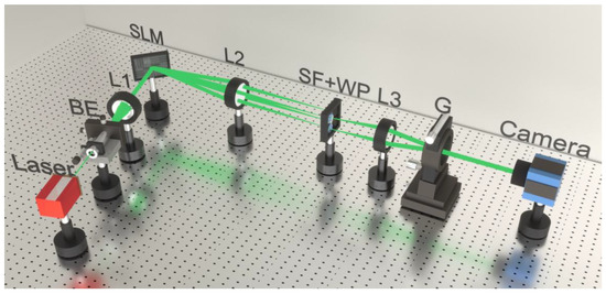
Figure 1.
Schematic of the experimental setup for generating the QGAB. BE, beam expander; L1 (f = 120 mm), L2 (f = 300 mm), and L3 (f = 150 mm), lenses; SLM, spatial light modulator; SF, spatial filter; WP, wave plates; G, Ronchi phase grating.
Figure 2 presents the intensity patterns and normalized Stokes parameters of the QGABs when , 1, and 2, respectively. The intensity patterns and polarization states of the QGABs are shown in the first column of Figure 2, and the second to fourth columns display the experimentally measured Stokes parameters , , and . The first row shows the QGAB with x-polarization when . From the total intensity pattern, it can be seen that the main spot is with maximum intensity, and the other secondary spots distribute with fourfold mirror symmetry. The x-polarization of the QGAB can be proved by the Stokes parameters, as the Stokes parameter is positive, while and are almost zero. The second row shows the QGAB when , and the QGAB is with radial polarizations on the wave front. The total intensity pattern is similar with the first row when , and the only difference is that there occurs a central V-point singularity when . As the QGAB is with variant linear polarizations, the Stokes parameter is almost zero, and and are azimuthally variant. When , the QGAB is also with azimuthally variant polarizations, and the linear polarizations rotate with two cycles along the azimuthal direction. The Stokes parameters when are similar to those when , which can prove the azimuthally variant polarization distributions of the QGABs. It is necessary to provide a theoretical analysis of the polarization distribution and the formation mechanism of the V-point singularity based on Equation (2). In Equation (2), is a common expression of the polarization of the cylindrical vector beam [28,29]. is the polarization azimuth, where m dictates the spatial period of the polarization rotation. When , the direction of the linear polarization state rotates through a full cycle along the azimuthal direction, forming a radially distributed polarization state. For , the polarization state rotates through two cycles along the azimuthal direction, leading to the formation of a high-order azimuthal polarization distribution, as depicted in Figure 2. The formation mechanism of the V-point singularity is due to the azimuthally variant polarizations, as it originates from the uncertainty of the orientations of linear polarizations around the singularity. When m increases from 1 to 2, the size of the V-point singularity becomes larger, which is due to the faster variance of the polarizations around the singularity when . The limited resolution of SLM cannot recognize or display the faster variations of polarizations, and the coherent cancellation also occurs between oppositely polarized lights near singularity. Thus, larger m leads to larger size of V-point singularity.
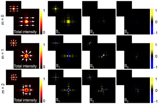
Figure 2.
The intensity patterns and Stokes parameters of the QGABs when , 1, and 2, respectively. The first column shows the measured total intensity patterns and the schematics of polarization states, and the second to fourth columns show the measured Stokes parameters , , and , respectively. The corresponding simulated results are given in the upper left insets. Each pattern has a dimension of mm mm.
3. Autofocusing and Self-Healing Properties of the QGAB
As is known, the most representative advantage of the traditional Airy beam is the excellent propagation properties. We now study the propagation properties of the generated QGAB with the beam propagation method (BPM) [30], which is a general beam propagation algorithm based on the wave equation under Fresnel approximation. Among different BPMs, we take the split-step spectral-domain method, which is a common numerical technique for simulating beam propagation. Then, the amplitude of the QGAB at distance can be calculated by [31]
where and are the Fourier transform and inverse Fourier transform, respectively. [, ] are the spatial frequency coordinates of the simulated propagation field. is the propagation constant of the QGAB in the free space. represents the deviation of the refractive index from the mean refractive index of the background. When and , we can calculate and simulate the propagation of the different components of the QGAB in a vacuum. The core idea of the BPM numerical algorithm is to divide the propagation length z into N equal segments, where the value of N must be sufficiently large to allow separate calculations of the diffraction term and the nonlinear term within each segment. Thus the propagation step in the BPM has to be small. In our calculations, we selected mm, which ensures accurate computational results. Additionally, this algorithm also requires a sufficiently large number of transverse grid points, and we selected a transverse grid of to ensure the adequate precision.
Figure 3 presents the propagation dynamics of the QGAB when . Figure 3a shows the simulated side view of the QGAB propagating in the y - z plane. Figure 3(b1–b6) illustrate the simulated transverse intensity patterns when mm, 35 mm, 70 mm, 105 mm, 140 mm, and 210 mm, respectively. Figure 3(c1–c6) display the corresponding experimental results. It can be observed from Figure 3a that the beam bends to the center in the radial direction. When the propagation distance z is 105 mm, the intensity of the QGAB is concentrated in a small area without the invocation of any lenses or nonlinearities. This indicates that the QGAB undergoes an autofocusing process in free space. In this process, the energy suddenly increases just before the focal point, and the focal point is located at a distance of mm. The autofocusing characteristic of the QGAB can be quantitatively described through a dimensionless parameter called the k-value [32,33], which is mathematically defined as , where and denote the maximum intensities at axial positions of and , respectively. This intensity ratio constitutes a principal quantitative metric for characterizing the autofocusing efficiency in propagating beams. The k-values are 1, 1.1333, 2.2154, 4.2079, 1.7619, and 0.4410 in Figure 3(b1–b6), and the corresponding experimental k-values are 1, 1.1447, 2.0395, 3.3553, 1.4605, and 0.92105, respectively. The minor discrepancy between simulated and experimental k-values can be attributed to the potential interference from ambient light sources during the experimental measurements. Obviously, the k-value is the largest at the focal point when mm. We need to discuss the parameter affecting the focal length during the autofocusing process. The transverse scale is the dominant parameter affecting the focal position during propagation. Specifically, a larger leads to a longer focal distance from the incident plane, meaning a greater focal length.
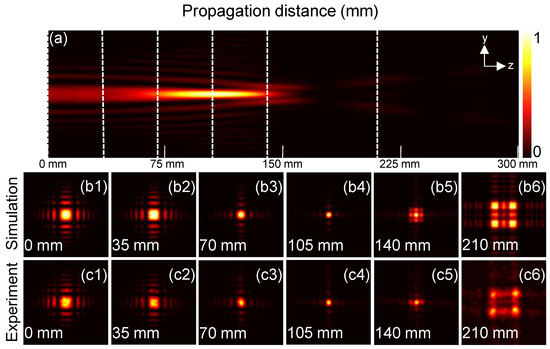
Figure 3.
Propagation of the QGAB when . (a) The simulated side view of the QGAB in the y–z plane. (b1–b6) The simulated transverse intensity distributions of the QGAB when mm, 35 mm, 70 mm, 105 mm, 140 mm, and 210 mm, respectively. (c1–c6) The corresponding experimental results. Each transverse intensity pattern has a dimension of .
Figure 4 shows the propagation dynamics of the QGAB when . Figure 4a depicts the simulated side view of the QGAB propagating in the y–z plane. Figure 4(b1–b6) display the simulated transverse intensity patterns when mm, 35 mm, 70 mm, 105 mm, 140 mm, and 210 mm, respectively. Figure 4(c1–c6) display the corresponding experimental results. From Figure 4a we can see that the radial size of the beam first increases and then decreases. The main spot exhibits a curved propagating trajectory in the z-direction. It can be seen from the transverse intensity patterns that when the propagation distance increases, the size of the V-point singularity also increases, and a hollow rectangular ring emerges in the central area of the QGAB when mm. When z increases from 35 mm to 105 mm, the hollow rectangular ring gradually shrinks, and the ring becomes the smallest when mm. By observing the propagation results of the two types of the QGABs when and , we can discover that both the beams show the autofocusing property. The autofocusing property of the QGAB can be applied in optical communications, optical tweezers, high-resolution microscopes, and so on.
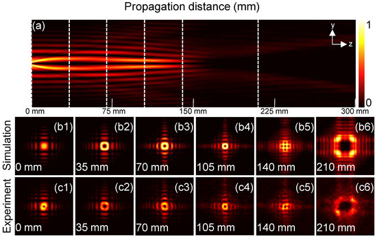
Figure 4.
Propagation of the QGAB when . (a) The simulated side view of the QGAB in the y–z plane. (b1–b6) The simulated transverse intensity distributions of the QGAB when mm, 35 mm, 70 mm, 105 mm, 140 mm, and 210 mm, respectively. (c1–c6) The corresponding experimental results. Each transverse intensity pattern has a dimension of .
Besides the above autofocusing property, the self-healing property is another fascinating propagation property of the QGAB. To investigate the self-healing property of the QGAB, we use a square obstruction precisely blocking the central maximum intensity spot in the input plane when . Figure 5 shows the self-healing behavior of the QGABs when and 1 during propagation. The first two rows display the case when . We can observe that there is a tendency for the central light spot to emerge at mm, and the central light spot gradually recovers when the propagating distance increases. The central light spot is restored at the position when mm, and the energy is basically concentrated to the central light spot. The third and fourth rows show the case when . We can observe that the energy emerges in the obstructed central region and begins to self-heal when mm. With the increasing distance, the energy starts to further converge towards the center. A rectangular ring begins to appear, and the degree of self-healing becomes more and more evident. At the position when mm, the rectangular ring appears and the obstructed central beam is basically restored. Obviously, the QGAB exhibits self-healing feature in propagation.
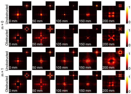
Figure 5.
The self-healing property of the QGABs when and 1 at the propagation distances of mm, 50 mm, 105 mm, 150 mm, and 200 mm. The first and third rows show the cases of the unobstructed beams, and the second and fourth rows show the cases of the centrally obstructed beams with square obstruction.
Based on the approach described in [27,34], we further calculate the similarity degree parameter S to quantitatively evaluate the self-healing capability of the QGAB. S ranges from 0 to 1, where 0 indicates a complete dissimilarity and 1 represents a complete identity. We calculate the S values of the centrally obstructed QGABs when and 1 at different propagation distances. The theoretical and experimental results are depicted at five distinct propagation distances when mm, 50 mm, 105 mm, 150 mm, and 200 mm. The similarity degree parameter S when is calculated by comparing the unobstructed and obstructed beams in the input plane, which indeed serves as a reference point. Figure 6a shows the comparative line plots of the similarity degree parameter S for the QGAB with square obstruction when . The simulated values of S are , , , , and , while the corresponding experimental values are , , , , and , respectively. It can be seen that the value of S becomes the maximum when mm, which is also the position of the self-focusing spot. Figure 6b shows the comparative line plots of the theoretical and experimental similarity degree parameter S for the QGAB with square obstruction when . The simulated values of S are , , , , and , while the corresponding experimental values are , , , , and , respectively. The similarity degree parameter S also reaches the maximum value when mm, which means that the self-healing effect becomes the best at this position. As shown in Figure 6, the theoretical predictions demonstrate excellent agreement with the experimental results. As the QGAB carries obvious self-healing property in propagation when meeting obstruction, we can speculate that the QGAB can be used in areas such as information transmission and information encryption.
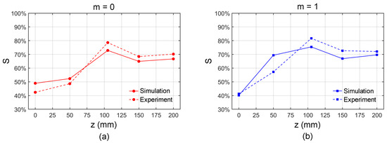
Figure 6.
The similarity degree parameter S at different propagation distances when mm, 50 mm, 105 mm, 150 mm, and 200 mm. (a,b) The cases when and 1.
The discrepancies between the theoretical and experimental results in this work, including errors in the intensity profiles, k-values, and similarity S, stem from multiple experimental aspects. The underlying physical mechanisms causing these discrepancies can be primarily attributed to the experimental conditions and limitations. Primarily, the limited pixel count of the SLM restricts the accuracy of the incident optical field modulation. Additionally, perfect alignment of the optical path is fundamentally unattainable, while the detector introduces inherent noise and the environment contributes ambient light interference. These combined factors collectively generate the observed experimental errors, manifesting as the deviations between theoretical predictions and measured results.
A systematic comparison between our generated QGAB and other beam types is essential. First, compared to conventional beams such as Laguerre–Gaussian beam and Bessel beam, the QGAB leverages the intrinsic properties of Airy functions, endowing it with superior self-focusing and self-healing capabilities during propagation. Second, compared to classical Airy beam and circular Airy beam, the QGAB exhibits fourfold symmetry with full wavefront coverage, significantly improving energy utilization efficiency. Third, unlike other dual- or quadruple-symmetric Airy beams, the QGAB employs an optimized superposition scheme, achieving 2.41 times of peak intensity enhancement over a single Airy beam, while the incorporated Gaussian envelope further maximizes propagation performance. In addition to its self-focusing and self-healing properties, the QGAB with quadruple-symmetry structure and Gaussian envelope may exhibit other distinctive characteristics, which will constitute important directions for future research. Through further modulation of its amplitude, phase, and polarization states, the QGAB could potentially demonstrate the physical properties including modulation of optical angular momentum, multi-focus formation characteristics, disturbance-resistant propagation, unique nonlinear effects, and so on.
We should provide a quantitative performance comparison of the QGAB and classical beams. Firstly, we compare the autofocusing performance of the QGAB and the CAB. The expression of the CAB is , where is the amplitude coefficient of the CAB, is a transverse scale, represents the decay parameter, and controls the beam radius in the initial plane. We set the initial parameters as , mm, , and mm. By choosing these parameters, the focal length of the CAB is equal to the focal length of the QGAB, and the parameters of the QGAB are consistent with those specified in Figure 3. Under these conditions, while maintaining identical total energy at the input plane, we conduct a comparative analysis between the QGAB and the CAB in theory. The maximum intensity value of the QGAB is 9.38 times the value of the CAB in the focal plane. The focal lengths of the QGAB and the CAB are both 105 mm, the focal depths of the two beams are 69 mm and 59 mm, and the energy efficiencies of the focal region are and for the two beams. It can be observed that the QGAB and the CAB each have their respective advantages and disadvantages in terms of autofocusing properties. Notably, the maximum intensity at the focal position of the QGAB is significantly higher than that of the CAB, which may find potential applications in optical processing, optical manipulation, and related fields. Secondly, we compare the self-healing performance of the QGAB and the Bessel beam when the QGAB obscures the main lobe, while the Bessel beam obscures the main ring. The expression of the Bessel beam is , where is the lth-order Bessel function of the first kind and is the transverse wave number. We choose and , and, in this way, the similarity degree S is approximately the same for both the QGAB and the Bessel beam in the input plane. The parameters of the QGAB are consistent with those specified in Figure 5 and Figure 6a. The calculated similarity degree S of the QGAB are , , , , and when mm, 50 mm, 105 mm, and 200 mm. The similarity degree S of the Bessel beam are , , , , and at the same positions. Obviously, the similarity degree S of the QGAB is better than that of the Bessel beam, and the recovery speed of the QGAB is also better, as S increases faster in propagation. Meanwhile, the similarity degree S of the QGAB is the maximum in the focal plane, and the physical origin of this phenomenon is due to the high concentration of energy when the QGAB propagates. The above comparison illustrates that under specific parameters, the QGAB has its own advantages in the autofocusing and self-healing capabilities, indicating that we can adjust the beam parameters according to specific application requirements.
As discussed above, the autofocusing and self-healing properties of the QGAB can be applied in regions such as optical communications, optical microscopes, and optical tweezers. Now we combine the characteristics of QGABs to more specifically elaborate on their potential advantages or unique value in certain application scenarios. Here, we list three application cases enabled by the beam’s unique properties. (1) Lens-free imaging. By leveraging the beam’s autofocusing capability, the lens-free imaging applications can be realized as the self-induced focus eliminates the need for conventional optical elements while maintaining resolution through self-reconstruction. (2) Secure communications. The unique polarization structure combined with self-healing characteristics provides dual physical-layer security, based on spatially variant polarization encoding and inherent resistance to obstruction-induced signal degradation. (3) Robustness in complex propagation conditions. It should also be noted that the QGAB demonstrates remarkable resilience in non-ideal propagation environments due to its inherent self-healing properties, which can be applied in many areas. When encountering scattering media or turbulence, the beam’s reconstructed wavefront maintains its characteristic intensity profile, though with some energy loss. Potential solutions to enhance robustness include optimizing the initial beam parameters and combining the QGAB with adaptive optics systems for dynamic wavefront correction in strongly perturbed conditions.
4. Conclusions
To conclude, we propose a kind of quadruple Gaussian Airy beam (QGAB) with fourfold symmetry. The QGAB was designed with the combination of Gaussian and Airy functions, and the polarization of the QGAB can be either singular or space-variant. We experimentally generated the QGAB by the experimental setup based on the SLM and 4f system. The propagation properties of the QGAB were then studied. The beam can autofocus to a solid spot and a hollow rectangular ring when and 1, respectively. When the QGAB is blocked by a central obstruction, the beam can self-heal and the similarity degree parameter reaches the maximum value at the position of the autofocusing spot. The QGAB enriches the family of the self-accelerating beams, and the autofocusing and self-healing properties can be applied in regions such as optical communications, optical microscopes, and optical tweezers.
Author Contributions
Conceptualization, X.-Z.G. and G.-D.T.; methodology, G.-D.T. and Y.P.; software, G.-D.T.; validation, X.-Z.G. and G.-D.T.; formal analysis, G.-D.T. and Y.P.; investigation, S.-T.X., M.-S.N. and H.-Z.C.; resources, R.-D.M. and Z.-X.M.; data curation, G.-D.T.; writing—original draft preparation, X.-Z.G. and G.-D.T.; writing—review and editing, X.-Z.G. and Y.P.; visualization, X.-Z.G.; supervision, S.-T.X., M.-S.N. and H.-Z.C.; project administration, R.-D.M. and Z.-X.M.; funding acquisition, X.-Z.G. and Y.P. All authors have read and agreed to the published version of the manuscript.
Funding
This research was funded by the National Natural Science Foundation of China (62475133, 62475134, 12174217), the Shandong Provincial Natural Science Foundation (ZR2023LLZ015, ZR2023MA040), the Higher Educational Youth Innovation Science and Technology Program of Shandong Province (2022KJ175, 2022KJ183), and the Urgent Talents Research Program for Key Support Regions of Shandong Province (2023TT2308).
Institutional Review Board Statement
Not applicable.
Informed Consent Statement
Not applicable.
Data Availability Statement
The data that support the findings of this study are available from the corresponding author upon reasonable request.
Conflicts of Interest
The authors declare no conflicts of interest.
References
- Siviloglou, G.A.; Broky, J.; Dogariu, A.; Christodoulides, D.N. Observation of accelerating Airy beams. Phys. Rev. Lett. 2007, 99, 213901. [Google Scholar] [CrossRef]
- Siviloglou, G.A.; Christodoulides, D.N. Accelerating finite energy Airy beams. Opt. Lett. 2007, 32, 979–981. [Google Scholar] [CrossRef] [PubMed]
- Ellenbogen, T.; Voloch Bloch, N.; Ganany Padowicz, A.; Arie, A. Nonlinear generation and manipulation of Airy beams. Nat. Photonics 2009, 3, 395–398. [Google Scholar] [CrossRef]
- Greenfield, E.; Segev, M.; Walasik, W.; Raz, O. Accelerating light beams along arbitrary convex trajectories. Phys. Rev. Lett. 2011, 106, 213902. [Google Scholar] [CrossRef] [PubMed]
- Jia, S.; Vaughan, J.C.; Zhuang, X.W. Isotropic three-dimensional super-resolution imaging with a self-bending point spread function. Nat. Photonics 2014, 8, 302–306. [Google Scholar] [CrossRef]
- Efremidis, N.K.; Chen, Z.G.; Segev, M.; Christodoulides, D.N. Airy beams and accelerating waves: An overview of recent advances. Optica 2019, 6, 686–701. [Google Scholar] [CrossRef]
- Baumgartl, J.; Mazilu, M.; Dholakia, K. Optically mediated particle clearing using Airy wavepackets. Nat. Photonics 2008, 2, 675–678. [Google Scholar] [CrossRef]
- Polynkin, P.; Kolesik, M.; Moloney, J. Filamentation of femtosecond laser Airy beams in water. Phys. Rev. Lett. 2009, 103, 123902. [Google Scholar] [CrossRef]
- Yu, J.H.; Zhang, L.H.; Wang, H.R.; Tao, P.C.; Cai, Y.J.; Hao, Z.Q.; Li, D.W. Filamentation of abruptly autofocusing ring-Airy laser pulses in air. Opt. Laser Technol. 2025, 184, 112441. [Google Scholar] [CrossRef]
- Hu, Y.; Tehranchi, A.; Wabnitz, S.; Kashyap, R.; Chen, Z.G.; Morandotti, R. Improved intrapulse Raman scattering control via asymmetric Airy pulses. Phys. Rev. Lett. 2015, 114, 073901. [Google Scholar] [CrossRef]
- Zhang, J.C.; Wu, G.B.; Chen, M.K.; Liu, X.Y.; Chan, K.F.; Tsai, D.P.; Chan, C.H. A 6G meta-device for 3D varifocal. Sci. Adv. 2023, 9, eadf8478. [Google Scholar] [CrossRef]
- Wang, J.; Hua, X.W.; Guo, C.L.; Liu, W.H.; Jia, S. Airy-beam tomographic microscopy. Optica 2020, 7, 790–793. [Google Scholar] [CrossRef] [PubMed]
- Zhou, Y.Z.; Zammit, P.; Zickus, V.; Taylor, J.M.; Harvey, A.R. Twin-Airy point-spread function for extended-volume particle localization. Phys. Rev. Lett. 2020, 124, 198104. [Google Scholar] [CrossRef]
- Zhang, X.L.; Hu, Y.W.; Zhang, X.; Li, Z.; Chen, Z.Q.; Fu, S.H. On-Demand Subwavelength-Scale Light Sculpting Using Nanometric Holograms. Laser Photon. Rev. 2023, 17, 2300527. [Google Scholar] [CrossRef]
- Abdollahpour, D.; Suntsov, S.; Papazoglou, D.G.; Tzortzakis, S. Spatiotemporal Airy light bullets in the linear and nonlinear regimes. Phys. Rev. Lett. 2010, 105, 253901. [Google Scholar] [CrossRef]
- Panagiotopoulos, P.; Papazoglou, D.; Couairon, A.; Tzortzakis, S. Sharply autofocused ring-Airy beams transforming into non-linear intense light bullets. Nat. Commun 2013, 4, 2622. [Google Scholar] [CrossRef] [PubMed]
- Koulouklidis, A.D.; Papazoglou, D.G.; Fedorov, V.Y.; Tzortzakis, S. Phase memory preserving harmonics from abruptly autofocusing beams. Phys. Rev. Lett. 2017, 119, 223901. [Google Scholar] [CrossRef]
- Hu, J.; Guo, Z.; Shi, J.; Jiang, X.; Chen, Q.; Chen, H.; He, Z.; Song, Q.; Xiao, S.; Yu, S.; et al. A metasurface-based full-color circular auto-focusing Airy beam transmitter for stable high-speed underwater wireless optical communications. Nat. Commun 2024, 15, 2944. [Google Scholar] [CrossRef]
- Zhang, G.B.; Gao, X.Z.; Li, Q.L.; Kong, Y.N.; Zhao, T.F.; Xu, S.T.; Ma, R.D.; Lü, J.Q.; Pan, Y. The manipulation of spin angular momentum for binary circular Airy beam during propagation. APL Photonics 2024, 9, 096114. [Google Scholar] [CrossRef]
- Hwang, C.Y.; Choi, D.; Kim, K.Y.; Lee, B. Dual airy beam. Opt. Express 2010, 18, 23504–23516. [Google Scholar] [CrossRef]
- Vyas, S.; Chia, Y.H.; Luo, Y. Conventional volume holography for unconventional Airy beam shapes. Opt. Express 2018, 26, 21979–21991. [Google Scholar] [CrossRef]
- Pang, Z.; Zhao, D. Partially coherent dual and quad Airy beams. Opt. Lett. 2019, 44, 4889–4892. [Google Scholar] [CrossRef]
- Ren, Z.; Wu, Q.; Shi, Y.; Chen, C.; Wu, J.; Wang, H. Production of accelerating quad Airy beams and their optical characteristics. Opt. Express 2014, 22, 15154–15164. [Google Scholar] [CrossRef]
- Wu, Z.; Zhu, D.; Jiang, Y.; Yu, W. Propagation properties of hollow rectangular quad-Airy beams. Optik 2023, 272, 170289. [Google Scholar] [CrossRef]
- Chen, Z.Z.; Zeng, T.T.; Qian, B.J.; Ding, J.P. Complete shaping of optical vector beams. Opt. Express 2015, 23, 17701–17710. [Google Scholar] [CrossRef]
- Pan, Y.; Gao, X.Z.; Zhang, G.L.; Li, Y.N.; Tu, C.H.; Wang, H.T. Spin angular momentum density and transverse energy flow of tightly focused kaleidoscope-structured vector optical fields. APL Photonics 2019, 4, 096102. [Google Scholar] [CrossRef]
- Zhao, T.F.; Li, Q.L.; Kong, Y.N.; Tan, G.D.; Gao, X.Z.; Pan, Y. Nondiffracting and self-healing properties of a multi-periodic full Poincaré beam. Opt. Lett. 2024, 49, 7110–7113. [Google Scholar] [CrossRef] [PubMed]
- Wang, X.L.; Ding, J.; Ni, W.J.; Guo, C.S.; Wang, H.T. Generation of arbitrary vector beams with a spatial light modulator and a common path interferometric arrangement. Optics Lett. 2007, 32, 3549–3551. [Google Scholar] [CrossRef] [PubMed]
- Zhan, Q. Cylindrical vector beams: From mathematical concepts to applications. Adv. Opt. Photonics 2009, 1, 1–57. [Google Scholar] [CrossRef]
- Feit, M.D.; Fleck, J.A., Jr. Light propagation in graded-index optical fibers. Appl. Optics 1978, 17, 3990–3998. [Google Scholar] [CrossRef]
- Glaser, A.K.; Chen, Y.; Liu, J.T.C. Fractal propagation method enables realistic optical microscopy simulations in biological tissues. Optica 2016, 3, 861–869. [Google Scholar] [CrossRef]
- Li, N.; Jiang, Y.F.; Huang, K.K.; Lu, X.H. Abruptly autofocusing property of blocked circular Airy beams. Opt. Express 2014, 22, 22847–22853. [Google Scholar] [CrossRef]
- Kong, Y.N.; Zhang, G.B.; Zhao, T.F.; Li, Q.L.; Tan, G.D.; Gao, X.Z.; Pan, Y. Propagation engineering of the complementary Gaussian-Airy beam. Opt. Laser Technol. 2025, 184, 112517. [Google Scholar] [CrossRef]
- Xu, Z.H.; Liu, X.L.; Chen, Y.H.; Wang, F.; Liu, L.; Monfared, Y.E.; Ponomarenko, S.A.; Cai, Y.J.; Liang, C.H. Self-healing properties of Hermite-Gaussian correlated Schell-model beams. Opt. Express 2020, 28, 2828–2837. [Google Scholar] [CrossRef]
Disclaimer/Publisher’s Note: The statements, opinions and data contained in all publications are solely those of the individual author(s) and contributor(s) and not of MDPI and/or the editor(s). MDPI and/or the editor(s) disclaim responsibility for any injury to people or property resulting from any ideas, methods, instructions or products referred to in the content. |
© 2025 by the authors. Licensee MDPI, Basel, Switzerland. This article is an open access article distributed under the terms and conditions of the Creative Commons Attribution (CC BY) license (https://creativecommons.org/licenses/by/4.0/).