Abstract
Dy3+:InF3 fiber shows promise for 4.4 μm mid-infrared lasing, but the much shorter lifetime of its upper laser level compared to the lower level causes inevitable self-termination. While cascade 4.4 μm/3 μm lasing has been proposed as a potential solution, this method faces complex configuration and an extremely high pump threshold (>30 W under continuous-wave operation), rendering it impractical for high-power use, especially given InF3’s soft-glass nature. To address the self-termination challenge and enable the low-threshold, high-efficiency lasing, this study proposes, for the first time to our knowledge, a dual-wavelength cascade-pumping scheme utilizing 2.8 μm and 2.4 μm pumps. Numerical simulations demonstrate that the dual-wavelength cascade-pumped Dy3+:InF3 fiber laser exhibits an optical-to-optical efficiency of up to 18.4% and a maximum slope efficiency of 38.5%. The total pump threshold is as low as 5.4 W, remarkably lower than that required by the cascade lasing approach. This work provides a viable solution and design guidelines for the development of 4 μm-class mid-infrared fiber lasers.
1. Introduction
Mid-infrared (mid-IR) lasers in the 3–5 μm wavelength range, which lie within the atmospheric transparency window and cover the fingerprint regions of numerous gas molecules, have significant application value and demand in fields such as environmental monitoring, biomedicine, and molecular spectroscopy [1,2,3,4,5,6]. Typically, such lasers can be obtained via optical parametric oscillations (OPOs) [7], quantum cascade lasers (QCLs) [8], and fiber lasers [2]. However, OPO laser sources show complex structures, high cost, and high susceptibility to environmental perturbations, while QCLs suffer from extremely limited output power. Among these approaches, fiber lasers, characterized by excellent beam quality, long-term stability, and power scalability, are drawing growing attention.
Currently, with the development of rare-earth doping and fluoride fiber fabrication technologies, 3 μm-class Er3+-doped, Ho3+-doped, and Dy3+-doped ZBLAN fiber lasers have achieved considerable progress and moved towards commercialization. Specifically, the output power of Er3+-doped ZBLAN fiber lasers has reached 70 W around 2.8 μm [9] and 15 W around 3.5 μm [10], while the output power of Ho3+-doped and Dy3+-doped ZBLAN fiber lasers around 3 μm has achieved 41 W [11] and 10 W [12], respectively. Another key focus lies in extending the emission wavelength of these systems to the 4 μm range. However, further extending the emission wavelength presents significant challenges, as the multiphonon absorption of ZBLAN fibers exhibits exponential growth with wavelengths exceeding 3.5 μm [13]. This necessitates the use of host materials with lower phonon energy. Chalcogenide fibers and InF3 fibers have been demonstrated as promising host materials, featuring lower phonon energy and an enhanced infrared transparency range compared to ZBLAN fibers [14,15,16,17,18,19]. Among these, achieving direct mid-IR oscillation in rare-earth-doped chalcogenide fibers remains challenging, primarily attributed to limited doping concentration and homogeneity of rare-earth ions. In contrast, InF3 fibers permit heavily doping with good homogeneity, paving the way for direct generation of 4 μm-class lasers [20]. Additionally, InF3 fibers possess a broad transparency range spanning from the visible to mid-IR region [5,21], offering greater flexibility in the pump source selection compared to most chalcogenides. Presently, a record output power of 200 mW has been achieved from a Ho3+-doped InF3 fiber laser operating near 3.9 μm [22], which represents the longest wavelength directly generated by a fluoride fiber laser in experimentally reported results to date.
Despite these advancements, extending laser emission beyond 4 μm remains a substantial challenge. In 2018, Majewski et al. observed ~4.4 μm fluorescence emission from Dy3+:InF3 fiber, originating from the 6H11/2 → 6H13/2 transition [23]. However, laser operation has yet to be achieved, primarily due to the inherent self-termination effect stemming from the significantly shorter lifetime of the upper energy level (6H11/2, 1 μs [24]) compared to the lower level (6H13/2, 500 μs [24]). While cascade lasing (simultaneous 4.4 μm and 3 μm emission) has been proposed as a potential solution, this approach suffers from a complex laser configuration and an extremely high pump threshold (>30 W under continuous-wave operation) [13]. Such characteristics render it impractical for high-power applications, particularly considering the soft-glass nature of InF3 materials. Additionally, theoretical analyses suggest that dual-wavelength pumping (2.85 μm and 4.09 μm) of a dysprosium-doped fiber laser could be feasible [25]. Nevertheless, the output power of this in-band pumping scheme is severely constrained by the inherently small absorption cross-section at 4.09 μm [26]. Furthermore, the scarcity of high-power pump sources at 4.09 μm also limits its practical implementation.
To address the self-termination challenge and enable the low-threshold, high-efficiency lasing from the Dy3+:InF3 fiber, this study proposes, for the first time to our knowledge, a dual-wavelength cascade-pumping scheme utilizing 2.8 μm and 2.4 μm pumps. Simulation results demonstrate that the dual-wavelength cascade-pumped Dy3+:InF3 fiber laser exhibits an optical-to-optical efficiency of up to 18.4% and a maximum slope efficiency of 38.5%. The total pump threshold is as low as 5.4 W, less than one fifth of that required by the cascade lasing approach under continuous-wave operation.
2. Numerical Model
Figure 1a displays the schematic of the energy level structure and energy transfer processes relevant to the proposed dual-wavelength cascade-pumped Dy3+:InF3 fiber laser at 4.4 μm. The 2.8 μm pump (pump 1) excites the Dy3+ ions from ground state level 6H15/2 to level 6H13/2. The 6H13/2 level is characterized by a long lifetime of 500 μs [25], thus resulting in a substantial accumulation of Dy3+ population on this level under the continuous pumping of a 2.8 μm laser source. Consequently, the level 6H13/2 can be regarded as a virtual ground state (VGS) for higher energy level transitions. With the pumping of a 2.4 μm laser source (pump 2), the Dy3+ ions on level 6H13/2 are excited to 6H9/2 + 6F11/2 level through virtual ground state absorption (VGSA). Given that 6H9/2 + 6F11/2 level has an extremely short lifetime of 0.05 μs, the ions on it are unstable and transit to the upper laser level 6H11/2 through rapid multiphonon relaxation (MPR). In a population inversion state, the transition between the 6H11/2 and the lower laser level 6H13/2 emits radiation at ~4.4 μm. Notably, benefiting from the energy recycling mechanism from level 6H13/2 to 6H11/2, the self-terminating effect faced by single pumping can be overcome.
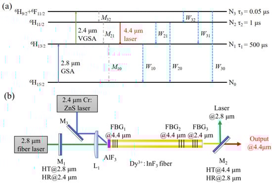
Figure 1.
(a) Energy level structure and energy transfer processes of the dual-wavelength cascade- pumped Dy3+:InF3 fiber laser at 4.4 μm. GSA: ground state absorption, VGSA: virtual ground state absorption, M: non-radiative decay rate, W: radiative decay rate. (b) Schematic diagram of the dual-wavelength cascade-pumped Dy3+:InF3 fiber laser. HT: high transmission, HR: high reflectivity, FBG: fiber Bragg grating.
The designed dual-wavelength cascade-pumped Dy3+:InF3 fiber laser is illustrated in Figure 1b. The pump lasers at 2.8 μm (pump 1) and 2.4 μm (pump 2) are focused into the core of the Dy3+:InF3 fiber via a convex lens L1 after passing through a dichroic mirror M1 (HT at 2.8 μm, HR at 2.4 μm) and a gold mirror M3 (HR at 2.4 μm), respectively. The cavity consists of fiber Bragg gratings FBG1 and FBG2, where FBG2 acts as an output coupler. To guarantee the optimal absorption of the 2.4 μm pump by the Dy3+:InF3 fiber, thereby lowering the pump threshold, FBG3 and M1 are employed to confine the 2.4 μm pump within the cavity. After filtering the unabsorbed 2.8 μm pump laser with a dichroic mirror M2 (HT at 4.4 μm, HR at 2.8 μm) placed at a 45° angle, the 4.4 μm laser is output. In practical applications of this laser configuration, an AlF3 endcap can be spliced to the fiber at the pump end, which enhances the fiber’s damage threshold.
Based on the energy level structure and energy transfer mechanisms of Dy3+ ions, the rate equations for the 4.4 μm dual-wavelength cascade-pumped Dy3+:InF3 fiber laser are established as follows:
In Equations (1)–(4), Ni represents the population density of Dy3+ ions at the i-th energy level. NDy stands for the doping concentration of Dy3+ ions in the InF3 fiber. Wij denotes the radiative decay rate from the upper energy level i to the lower energy level j, and Mij is the non-radiative decay rate for the transition of Dy3+ ions from the upper energy level i to the lower level j. RGSA and RVGSA respectively represent the rates of GSA at 2.8 μm and VGSA at 2.4 μm, while RSE denotes the stimulated emission rate of the 4.4 μm signal light, which can be given by the following:
where λp1 and λp2 denote the wavelengths of pump 1 and pump 2, respectively, and λs represents the laser wavelength. h stands for the Planck constant and c represents the speed of light in a vacuum. Γp1, Γp2, and Γs denote the power filling factors for the 2.8 μm pump, 2.4 μm pump, and 4.4 μm laser, respectively, where the filling factor is defined as Γx = 1 − exp[−2(rcore/ω)] with x = p1, p2, s. The signal is assumed to follow a Gaussian distribution with a mode radius given by ω = rcore (0.65 + 1.619V−1.5 + 2.876V−6), where rcore denotes the fiber core radius. V = 2πrcoreNA/λx is the normalized frequency for the pump or laser, where NA (0.16) denotes the numerical aperture, and Acore = π refers to the cross-sectional area of the Dy3+:InF3 fiber core. The term σij represents the absorption cross-section for the transitions from lower energy level i to upper energy level j (i < j), or the emission cross-section for the transitions from upper energy level i to lower energy level j (i > j). Specifically, σ10 and σ31 represent the emission cross-sections at pump 1 and pump 2 wavelengths, respectively, while σ01 and σ13 denote the corresponding absorption cross-sections. For the laser signal, σ21 and σ12 are the emission cross-section and absorption cross-section at the signal wavelength, respectively. Pp1, Pp2, and Ps denote the longitudinally varying powers of pump 1, pump 2, and the signal light along the fiber.
The positive and negative signs of these power values indicate the forward and backward propagation directions along the fiber, respectively. The propagation equations for the power evolution of the pump lasers and the laser light along the propagation can be obtained as follows:
where αp1, αp2, and αs denote the background loss coefficients of the InF3 fiber at pump and signal wavelengths. represents the spontaneous emission power, which is defined as the following:
where ΔASE is the noise bandwidth of the amplified spontaneous emission.
The powers of the pump lasers and laser light at both ends of the fiber are subjected to the following boundary conditions:
where Pinput_p1 and Pinput_p2 are the powers launched into the fiber core for pump 1 and pump 2, respectively. R1,p1 and R1,p2 represent the reflectivities of FBG1 at pump 1 and pump 2 wavelengths, respectively. R0,p2 represents the reflectivity of M1 at pump 2 wavelength. Similarly, R2,p1 and R2,p2 represent the reflectivities of FBG2 at pump 1 and pump 2 wavelengths, respectively. R3,p1 and R3,p2 represent the reflectivities of FBG3 at pump 1 and pump 2 wavelengths, respectively. R1,s, R2,s, and R3,s are the reflectivities of FBG1, FBG2, and FBG3 at the laser wavelength.
For the laser system under study, the output power Poutput of the fiber laser is given by the following equation:
Based on the defined boundary conditions, the rate equations and propagation equations are numerically solved using the fourth-order Runge–Kutta algorithm [27]. In the simulation, the fiber length L is uniformly discretized, with transient solutions computed for each spatial segment until reaching steady state. Subsequently, the power distributions of the pump lasers and the signal laser light for each segment are calculated by applying the finite difference method [28]. It should be noted that unless otherwise specified, all simulations utilize the parameters in Table 1.

Table 1.
Parameters used in the simulations.
For σ13 and σ31, there are no direct experimental measurement data for reference. However, approximate values can be scaled from the absorption and emission cross-sections of Dy3+-doped chalcogenide glass [13]. Studies indicate that the fluorescence spectral shapes of Dy3+-doped fluoride glass exhibit minimal deviation from the chalcogenide glass host, primarily showing reduced cross-section intensity [13]. Using σ12 and σ21 scaling factors as a reference (chalcogenide host: σ12 = 8.5 × 10⁻²⁵ m2, σ21 = 9.8 × 10⁻²⁵ m2 [26]; fluoride host: σ12 = 1.51 × 10⁻²⁵ m2, σ21 = 2.06 × 10⁻²⁵ m2), we obtain scaling factors of 5.63 (absorption cross-section) and 4.76 (emission cross-section). Applying these to chalcogenide glass values at 2.4 μm (absorption cross-section: 9.79 × 10⁻²⁵ m2, emission cross-section: 9.14 × 10⁻²⁵ m2 [26]), we derive fluoride glass cross-sections of σ13 = 1.74 × 10⁻²⁵ m2 and σ31 = 1.92 × 10⁻²⁵ m2 at 2.4 μm. These estimated cross-sections at 2.4 μm are comparable to those at 2.8 μm, which is consistent with these chalcogenide fibers.
3. Simulation Results and Discussion
In the proposed dual-wavelength cascade-pumped mid-infrared fiber laser system, the gain of the 4.4 μm laser is primarily driven by the 2.4 μm pump. However, the 2.8 μm pump intensity significantly impacts the VGSA of 2.4 μm. Figure 2a depicts the output power of the 4.4 μm laser versus 2.8 μm pump power P1 at different fiber lengths, with 2.4 μm pump power P2 fixed at 20 W. For all the curves, laser oscillation begins at a low pump power level (P1th = ~1 mW), with the output power initially increasing with the 2.8 μm pump power P1. After reaching their respective peaks, the output powers of all curves decline as the 2.8 μm pump power P1 continues to increase. This decrease can be attributed to the excessive 2.8 μm pump power, which leads to particle accumulation in the lower energy level and thus diminishes the population inversion between the upper and lower energy levels. With increasing fiber length, the laser output power declines more rapidly due to the higher fiber loss and stronger signal light reabsorption.
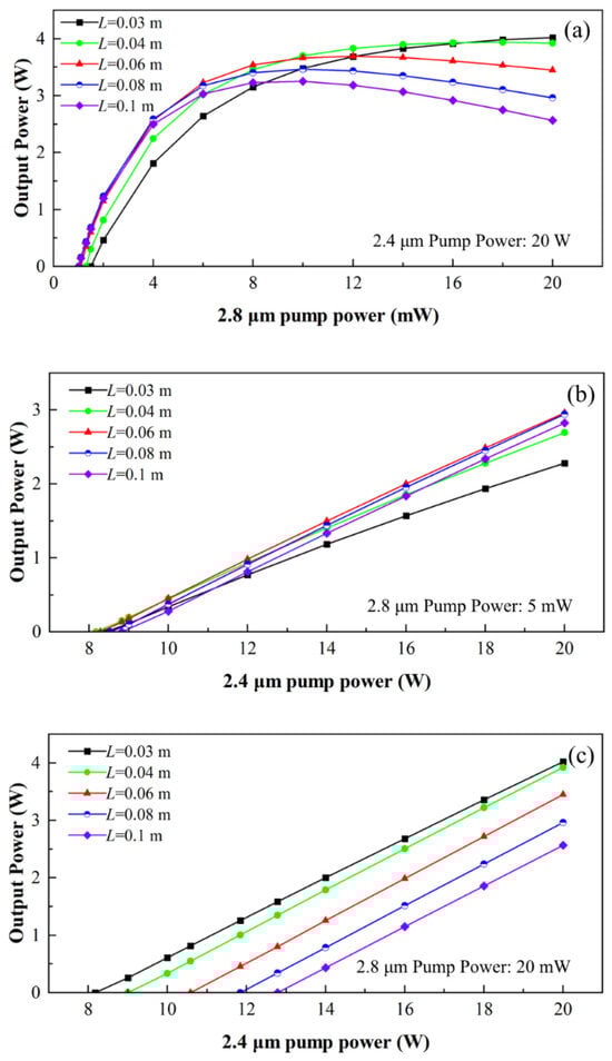
Figure 2.
Simulated output power of the Dy3+:InF3 fiber laser for different fiber lengths: L = 0.04, 0.06, 0.08, 0.1 m. (a) Output power vs. 2.8 μm pump power P1. (b) Output power vs. 2.4 μm pump power P2 with 2.8 μm pump power P1 fixed at 5 mW. (c) Output power vs. 2.4 μm pump power P2 with 2.8 μm pump power P1 fixed at 20 mW.
Figure 2b,c illustrate the relationship between the output power and the 2.4 μm pump power P2 for different fiber lengths, with the 2.8 μm pump power P1 fixed at 5 mW and 20 mW, respectively. As shown in Figure 2b, the output power increases linearly with 2.4 μm pump power P2. Relatively shorter fiber lengths correspond to lower pump thresholds P2th, achieving a minimum threshold of 8 W at a fiber length of 0.04 m. However, longer fiber lengths enable a more rapid rise in output power. In Figure 2c, when 2.8 μm pump power P1 is increased to 20 mW, the pump threshold P2th increases accordingly, with distinct magnitudes of growth. The longer the fiber, the more pronounced the threshold increase. Additionally, the slope efficiency of the output power is almost the same across all the fiber lengths.
Figure 3a shows the output power of the Dy3+:InF3 fiber laser versus 2.4 μm pump power P2 at 2.8 μm pump power P1 = 8, 12, 16, and 20 mW. Increasing 2.8 μm pump power P1 would elevate the pump threshold P2th, as higher P1 causes particle accumulation in the lower laser level, requiring a higher 2.4 μm pump power to achieve population inversion. Figure 3b depicts the output power versus 2.8 μm pump power P1 for 2.4 μm pump power P2 = 8, 12, 16, and 20 W. The results demonstrate that the influence of 2.8 μm pump power P1 becomes more pronounced with higher 2.4 μm pump power P2. No laser emission occurs at 2.4 μm pump power P2 = 8 W due to insufficient population inversion. Under optimized pumping (P1 = 12 mW, P2 = 20 W), the fiber laser yields a maximum output power of 3.69 W, with the corresponding overall optical-to-optical efficiency of 18.4%.
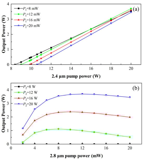
Figure 3.
Simulated output power of the Dy3+:InF3 fiber laser for fiber length L = 0.06 m and output coupler reflectivity R2,s = 95%. (a) Output power vs. 2.4 μm pump power P2 for 2.8 μm pump power P1 = 8, 12, 16, and 20 mW. (b) Output power vs. 2.8 μm pump power P1 at 2.4 μm pump power P2 = 8, 12, 16, and 20 W.
Figure 4a,b show the slope efficiency (with respect to 2.8 μm pump power P1) and pump threshold (P2th) of the Dy3+:InF3 fiber laser versus fiber length at 2.8 μm pump power P1 = 12 mW, with output coupler reflectivity R2,s = 90–98%. The maximum slope efficiency of 38.5% is achieved at the minimum output coupler reflectivity R2,s = 90% and fiber length L = 0.08 m, while the minimum P2th of 5.4 W is achieved at the maximum output coupler reflectivity R2,s = 98% and fiber length L = 0.03 m. The total pump threshold is markedly lower than the >30 W threshold required for the single-wavelength pumped cascade lasing approach under continuous-wave operation [13]. Figure 4c depicts the output power versus 2.8 μm pump power P1 at 2.4 μm pump power P2 = 20 W, fiber length L = 0.06 m, and output coupler reflectivity R2,s = 90–98%. It can be observed that 2.8 μm pump power P1 = 12 mW is identified as the optimal value for achieving high output power. Furthermore, when 2.8 μm pump power P1 exceeds 8 mW, output coupler reflectivity, R2,s = 95%, exhibits the optimal output power performance.
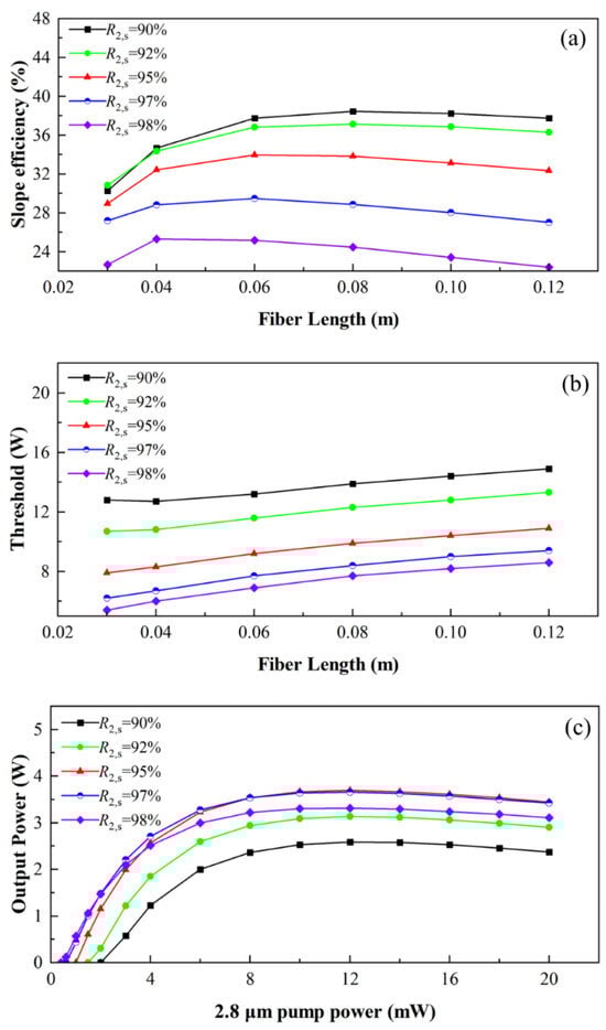
Figure 4.
Simulated output characteristics of the Dy3+:InF3 fiber laser. (a) Slope efficiency (with respect to 2.8 μm pump power P1) and (b) pump threshold (P2th) vs. fiber length at 2.8 μm pump power P1 =12 mW, and output coupler reflectivity R2,s = 90–98%. (c) Output power vs. 2.8 μm pump power P1 at 2.4 μm pump power P2 = 20 W, fiber length L = 0.06 m, and output coupler reflectivity R2,s = 90–98%.
Under optimized pumping conditions (P1 = 12 mW, P2 = 20 W) and an output coupler reflectivity R2,s = 95%, further analysis is conducted on the effect of Dy3+ doping concentration on the laser performance, as depicted in Figure 5. When the dopant concentration of Dy3+ rises from 0.3 mol% to 0.7 mol%, the optimal fiber length for peak output power decreases from 0.06 m to 0.03 m, and the corresponding peak output power increases from 3.49 W to 4 W. These results highlight that enhanced efficiency can be achieved by employing gain fibers with higher Dy3+ doping concentrations.
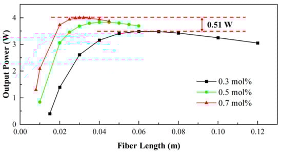
Figure 5.
Simulated output power of the Dy3+:InF3 fiber laser as a function of the fiber length for different doping concentrations.
The above simulation results are based on an estimated value of σ13 = 1.74 × 10⁻²⁵ m2. Considering potential discrepancies in the practical scenarios, we further investigate the influence of σ13 on optical-to-optical conversion efficiency under optimized pumping conditions (P1 = 12 mW, P2 = 20 W) and an output coupler reflectivity R2,s = 95%, as shown in Figure 6a. As observed, the optical-to-optical conversion efficiency increases from 12.8% at σ13 = 1 × 10⁻²⁵ m2 to 21.7% at σ13 = 3 × 10⁻²⁵ m2. Based on these results, we believe much higher optical-to-optical conversion efficiency can be achieved in Dy3+-doped chalcogenide fiber lasers theoretically, since such fibers exhibit an absorption cross-section of up to 9.79 × 10⁻²⁵ m2 [26].
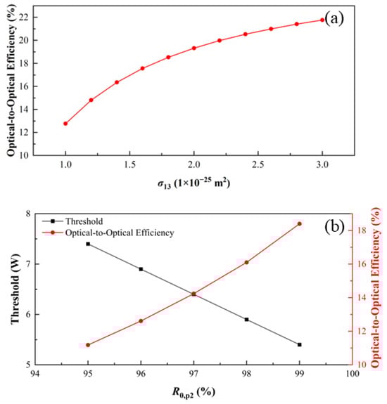
Figure 6.
(a) Influence of σ13 on optical-to-optical conversion efficiency under optimized pumping conditions (P1 = 12 mW, P2 = 20 W) and an output coupler reflectivity R2,s = 95%. (b) Dependence of pumping threshold (under conditions: P1 = 12 mW, R2,s = 98%, L = 0.03 m) and optical-to-optical conversion efficiency (under conditions: P1 = 12 mW, P2 = 20 W, R2,s = 95%, L = 0.06 m) on 2.4 μm pump laser escape loss.
Furthermore, we assume that the 2.4 μm pump laser undergoes reflection between M1 and FBG3 with 1% escape loss, which might be higher in practical implementations. Thus, we investigate the impacts of such loss on the pumping threshold (under conditions: P1 = 12 mW, R2,s = 98%, L = 0.03 m) and optical-to-optical conversion efficiency (under conditions: P1 = 12 mW, P2 = 20 W, R2,s = 95%, L = 0.06 m) by varying R0,p2 from 95% to 99%. As illustrated in Figure 6b, with a decrease in R0,p2 (i.e., an increase in loss), the pump threshold increases from 5.4 W to 7.4 W, while the optical-to-optical conversion efficiency decrease from 18.4% to 11.2%. Therefore, in the practical scenarios, to achieve low-threshold and high-efficiency operation of the laser, such loss should be minimized. For example, an antireflection coating can be used to reduce the reflection loss of the lens, and an aspherical lens can be employed to reduce aberrations of the focused spot. We would like to mention that Majewski et al. numerically demonstrated that pulse pumping can significantly lower the lasing threshold compared to continuous-wave pumping [13]. Thus, employing a 2.4 μm pulsed laser as the pumping source is expected to further reduce the threshold of the dual-wavelength cascade-pumped laser.
4. Conclusions
In summary, this work presents a dual-wavelength cascade-pumping strategy to tackle the self-termination limitation in Dy3+:InF3 fiber lasers, enabling low-threshold, high-efficiency 4.4 μm emission. Comprehensive simulation results demonstrate that this dual-wavelength cascade configuration achieves an overall optical-to-optical efficiency of up to 18.4% and a maximum slope efficiency of 38.5%. The total pump threshold is as low as 5.4 W, which is remarkably lower than the >30 W threshold required for single-wavelength pumped cascade lasing under continuous-wave operation. Furthermore, we identify that further efficiency enhancement can be realized by appropriately increasing the Dy3+ doping concentration. This study not only provides a viable technical pathway for developing low-threshold, high-efficiency 4.4 μm Dy3+:InF3 fiber lasers, but also paves the way for their experimental implementation in 4 μm-class mid-infrared fiber laser systems.
Author Contributions
Conceptualization, P.T., J.L. and Y.W.; methodology, P.T.; software, L.Y., S.H., X.L. and Y.H.; validation, L.Y. and S.H.; formal analysis, L.Y., S.H. and J.L.; investigation, L.Y., S.H. and J.G.; resources, P.T.; data curation, L.Y. and J.G.; writing—original draft preparation, L.Y.; visualization, L.Y., S.H. and X.L.; writing—review and editing, P.T., J.L. and Y.W.; supervision, P.T., J.L. and Y.W.; project administration, Y.W.; funding acquisition, P.T. All authors have read and agreed to the published version of the manuscript.
Funding
This work was supported by Hunan Provincial Natural Science Foundation of China (2023JJ30596).
Data Availability Statement
Data underlying the results presented in this paper are not publicly available at this time but may be obtained from the authors upon reasonable request.
Conflicts of Interest
The authors declare no conflicts of interest.
References
- Jackson, S.D. Towards High-Power Mid-Infrared Emission from a Fiber Laser. Nat. Photonics 2012, 6, 423–431. [Google Scholar] [CrossRef]
- Tang, P.; Wang, Y.; Vicentini, E.; Canella, F.; Molteni, L.M.; Coluccelli, N.; Laporta, P.; Galzerano, G. Single-Frequency Dy:ZBLAN Fiber Laser Tunable in the Wavelength Range from 2.925 to 3.250 μm. J. Lightwave Technol. 2022, 40, 2489–2493. [Google Scholar] [CrossRef]
- Hai, T.; Xie, G.; Ma, J.; Shao, H.; Qiao, Z.; Qin, Z.; Sun, Y.; Wang, F.; Yuan, P.; Ma, J.; et al. Pushing Optical Switch into Deep Mid-Infrared Region: Band Theory, Characterization, and Performance of Topological Semimetal Antimonene. ACS Nano 2021, 15, 7430–7438. [Google Scholar] [CrossRef]
- Wu, Z.; Cao, J.; Liu, W.; Shang, C.; Fan, Z.; Yue, H.; Wei, C.; Liu, Y. Theoretical Study on Cascade Energy-Transfer Pumping Heavily Holmium-Doped Fluoroindate Fiber Laser at ~4 μm with High-Efficiency. Opt. Laser Technol. 2025, 181, 111939. [Google Scholar] [CrossRef]
- Loconsole, A.M.; Francione, V.V.; Anelli, F.; Taccheo, S.; Prudenzano, F. Mid-IR Amplification Based on a Pr3+: InF3 Optical Fiber in the Range 3.8–4.2 μm. J. Lightwave Technol. 2025, 43, 5451–5458. [Google Scholar] [CrossRef]
- Guo, C.; Lin, J.; Tang, Z.; Li, K.; Tu, L.; Wang, J.; Liu, X.; Ruan, S. Theoretical Analysis of ESA-Enhanced 2.8 μm Lasing in Er-Doped ZBLAN Fiber Lasers. J. Lightwave Technol. 2022, 40, 4397–4414. [Google Scholar] [CrossRef]
- Ebrahim-Zadeh, M.; Chaitanya Kumar, S.; Devi, K. Yb-Fiber-Laser-Pumped Continuous-Wave Frequency Conversion Sources from the Mid-Infrared to the Ultraviolet. IEEE J. Select. Top. Quantum Electron. 2014, 20, 350–372. [Google Scholar] [CrossRef]
- Razeghi, M.; Bandyopadhyay, N.; Bai, Y.B.; Lu, Q.Y.; Slivken, S. Recent Advances in Mid Infrared (3–5 μm) Quantum Cascade Lasers. Opt. Mater. Express 2013, 3, 1872–1884. [Google Scholar] [CrossRef]
- Newburgh, G.A.; Dubinskii, M. Power and Efficiency Scaling of Er: ZBLAN Fiber Laser. Laser Phys. Lett. 2021, 18, 095102. [Google Scholar] [CrossRef]
- Lemieux-Tanguay, M.; Fortin, V.; Boilard, T.; Paradis, P.; Maes, F.; Talbot, L.; Vallée, R.; Bernier, M. 15 W Monolithic Fiber Laser at 3.55 μm. Opt. Lett. 2022, 47, 289. [Google Scholar] [CrossRef]
- Aydin, Y.O.; Fortin, V.; Vallée, R.; Bernier, M. Towards Power Scaling of 2.8 μm Fiber Lasers. Opt. Lett. 2018, 43, 4542. [Google Scholar] [CrossRef]
- Fortin, V.; Jobin, F.; Larose, M.; Bernier, M.; Vallée, R. 10-W-Level Monolithic Dysprosium-Doped Fiber Laser at 3.24 μm. Opt. Lett. 2019, 44, 491. [Google Scholar] [CrossRef]
- Majewski, M.R.; Jackson, S.D. Numerical Design of 4 μm-Class Dysprosium Fluoride Fiber Lasers. J. Lightwave Technol. 2021, 39, 5103–5110. [Google Scholar] [CrossRef]
- Xiao, X.; Xu, Y.; Cui, J.; Liu, X.; Cui, X.; Wang, X.; Dai, S.; Guo, H. Structured Active Fiber Fabrication and Characterization of a Chemically High-purified Dy3+ -doped Chalcogenide Glass. J. Am. Ceram. Soc. 2020, 103, 2432–2442. [Google Scholar] [CrossRef]
- Starecki, F.; Louvet, G.; Ari, J.; Braud, A.; Doualan, J.-L.; Chahal, R.; Hafienne, I.; Boussard-Plédel, C.; Nazabal, V.; Camy, P. Dy3+ Doped GaGeSbSe Fiber Long-Wave Infrared Emission. J. Lumin. 2020, 218, 116853. [Google Scholar] [CrossRef]
- Yang, A.; Sun, M.; Ren, H.; Lin, H.; Feng, X.; Yang, Z. Dy3+-Doped Ga2S3-Sb2S3-La2S3 Chalcogenide Glass for Mid-Infrared Fiber Laser Medium. J. Lumin. 2021, 237, 118169. [Google Scholar] [CrossRef]
- Saad, M. Indium Fluoride Glass Fibers. In Proceedings of Laser Refrigeration of Solids V; SPIE Optica Publishing Group: San Francisco, CA, USA, 2012; p. 82750D. [Google Scholar] [CrossRef]
- Saad, M.; Pafchek, R.; Foy, P.; Jiang, Z.; Gardner, D.; Hawkins, P. Indium Fluoride Glass Fibers for Mid-Infrared Applications. In Proceedings of the Workshop on Specialty Optical Fibers and Their Applications; OSA: Hong Kong China, 2015; p. WW4A.3. [Google Scholar] [CrossRef]
- Anelli, F.; Loconsole, A.M.; Prudenzano, F. Mid-Infrared Optical Fiber Devices: Challenges, Advances and Applications. Opt. Mater. 2025, 167, 117294. [Google Scholar] [CrossRef]
- Zhou, F.; Li, J.; Luo, H.; Quellette, F.; Liu, Y. Numerical Analysis of 3.92 μm Dual-Wavelength Pumped Heavily-Holmium-Doped Fluoroindate Fiber Lasers. J. Lightwave Technol. 2021, 39, 633–645. [Google Scholar] [CrossRef]
- Grebnev, K.; Perminov, B.; Fernandez, T.T.; Fuerbach, A.; Chernysheva, M. Fluoride and Chalcogenide Glass Fiber Components for Mid-Infrared Lasers and Amplifiers: Breakthroughs, Challenges, and Future Perspective. APL Photonics 2024, 9, 110901. [Google Scholar] [CrossRef]
- Maes, F.; Fortin, V.; Poulain, S.; Poulain, M.; Carrée, J.-Y.; Bernier, M.; Vallée, R. Room-Temperature Fiber Laser at 3.92 μm. Optica 2018, 5, 761. [Google Scholar] [CrossRef]
- Majewski, M.R.; Woodward, R.I.; Carreé, J.-Y.; Poulain, S.; Poulain, M.; Jackson, S.D. Emission beyond 4 μm and Mid-Infrared Lasing in a Dysprosium-Doped Indium Fluoride (InF3) Fiber. Opt. Lett. 2018, 43, 1926. [Google Scholar] [CrossRef]
- Quimby, R.S.; Saad, M. Pathways to a 4 μm Dy3+ Fluoride Glass Fiber Laser. In Proceedings of the Lasers Congress; OSA: Boston, MA, USA, 2016; p. JTu2A.34. [Google Scholar] [CrossRef]
- Falconi, M.C.; Palma, G.; Starecki, F.; Nazabal, V.; Troles, J.; Taccheo, S.; Ferrari, M.; Prudenzano, F. Design of an Efficient Pumping Scheme for Mid-IR Dy3+:Ga5Ge20Sb10S65 PCF Fiber Laser. IEEE Photon. Technol. Lett. 2016, 28, 1984–1987. [Google Scholar] [CrossRef]
- Xiao, Y.; Cui, J.; Xiao, X.; Xu, Y.; Guo, H. Modeling of 1.7-μm and 2.4-μm Dual-Wavelength Pumped 4.3-μm Dysprosium-Doped Chalcogenide Fiber Lasers. IEEE J. Quantum Electron. 2024, 60, 1–6. [Google Scholar] [CrossRef]
- Yang, J.L.; Tang, Y.L.; Zhang, R.; Xu, J.Q. Modeling and Characteristics of Gain-Switched Diode-Pumped Er-Yb Codoped Fiber Lasers. IEEE J. Quantum Electron. 2012, 48, 1560–1567. [Google Scholar] [CrossRef]
- Cheng, Z.; Zhang, Z.; Wang, R.; Wang, S.; Li, X.; Chormaic, S.N.; Jia, S.; Wang, P. Numerical Modeling of Dual-Wavelength Pumped Heavily-Ho3+-Doped Fluoroindate Fiber Lasers with Efficient Output at 3.92 μm. J. Lightwave Technol. 2023, 41, 7021–7028. [Google Scholar] [CrossRef]
- Quimby, R.S.; Saad, M. Anomalous Nonradiative Decay in Dy-Doped Glasses and Crystals. Opt. Lett. 2017, 42, 117. [Google Scholar] [CrossRef]
- Quimby, R.S.; Saad, M. Dy:Fluoroindate Fiber Laser at 4.5 μm with Cascade Lasing. In Proceedings of the Advanced Solid-State Lasers Congress; OSA: Paris, France, 2013; p. AM2A.7. [Google Scholar] [CrossRef]
- Flórez, A.; Jerez, V.A.; Flórez, M. Optical Transitions Probabilities of Dy3+ Ions in Fluoroindate Glass. J. Alloys Compd. 2000, 303–304, 355–359. [Google Scholar] [CrossRef]
- Majewski, M.R.; Jackson, S.D. Highly Efficient Mid-Infrared Dysprosium Fiber Laser. Opt. Lett. 2016, 41, 2173. [Google Scholar] [CrossRef]
Disclaimer/Publisher’s Note: The statements, opinions and data contained in all publications are solely those of the individual author(s) and contributor(s) and not of MDPI and/or the editor(s). MDPI and/or the editor(s) disclaim responsibility for any injury to people or property resulting from any ideas, methods, instructions or products referred to in the content. |
© 2025 by the authors. Licensee MDPI, Basel, Switzerland. This article is an open access article distributed under the terms and conditions of the Creative Commons Attribution (CC BY) license (https://creativecommons.org/licenses/by/4.0/).