Abstract
We demonstrate a fiber-guided atom interferometer in a far-off-resonant trap (FORT) of 100 μK. The differential light shift (DLS) introduced by the FORT leads to the inhomogeneous dephasing of the tightly trapped atoms inside a hollow-core fiber. The DLS-induced dephasing is greatly suppressed in Doppler-insensitive interferometry. The spin coherence time is extended to 13.4 ms by optimizing the coupling of the trapping laser beam into a quasi-single-mode hollow-core anti-resonant fiber. The Doppler-sensitive interferometry shows a much shorter coherence time, indicating that the main limits to our fiber-guided atom interferometer are the wide axial velocity distribution and the irregular modes of the Raman laser beams inside the fiber. This work paves the way for portable and miniaturized quantum devices, which have advantages for inertial sensing at arbitrary orientations and in dynamic environments.
1. Introduction
A hollow-core photonic crystal fiber (HC-PCF) [1,2,3,4] is a novel type of microstructured optical fiber that guides laser beams in air for transmission. Inside the HC-PCF, the diffraction-free and low-loss light field provides an ideal platform for long-distance, transportable, and enhanced atom–photon interactions. Based on the platform, the frontiers of quantum information technology have developed rapidly, including precision spectroscopy [5], Rydberg atoms [6,7], quantum memories [8,9], and quantum computing [10]. This makes the fiber-guided atom interferometer a promising candidate for portable and miniaturized quantum devices.
Compared to atom interferometers in free space [11,12], fiber-guided atom interferometers have potential in applications such as inertial sensing at arbitrary orientations or in highly dynamic environments as a relatively deep FORT can tightly trap laser-cooled atoms in the radial direction [13]. For instance, a 100 μK FORT inside a hollow-core fiber with a mode-field diameter of 20 μm provides a potential barrier, corresponding to the maximum acceleration of approximately 1000 m/s2 [14]. Currently, an inertia-sensitive atom interferometer inside the HC-PCF has been realized [15]. However, the severe decay regarding the contrast is mainly due to the inhomogeneous broadening of the DLS between the hyperfine ground-state energy levels. This substantially limits the development of fiber-guided atom interferometers.
To date, several methods have been demonstrated to be effective in canceling the DLS. Our previous study showed the suppression of the DLS in microwave Ramsey interferometry by introducing a weak compensation laser beam into the HC-PCF, whose frequency is tuned in between two hyperfine levels of atoms [16]. However, the method of optical compensation [17] is limited by the mode mismatching of laser beams of different wavelengths inside the HC-PCF and the fluctuations in optical power. Another method compensates for the DLS by implementing an additional magic magnetic field along the elliptically polarized trapping laser beam. The equivalent magnetic field generated by the trapping laser beam will induce a Zeeman shift for the clock transition. Normally, the method of Zeeman-like compensation [18,19] requires a strong external magnetic field of a few Gauss at the expense of a large magnetic-field sensitivity and high coils power consumption. In addition, to minimize the DLS-induced dephasing, an approach for cooling atoms directly inside the HC-PCF has been proposed. The in-fiber cooling allows a shallow FORT of a few hundred nano-Kelvin in the interferometry to reduce the DLS and improve the interferometer time up to 20 ms [20]. However, a relatively shallow FORT cannot provide a sufficient potential barrier. This makes fiber-guided atom interferometers lose the advantages in the field of inertial sensing at arbitrary orientations and dynamic environments.
In this paper, we report on a tightly trapped atom interferometer inside a hollow-core fiber and the extension of the interrogation times to tens of milliseconds in a relatively deep FORT. This is achieved because we reverse the DLS-induced inhomogeneous dephasing by optimizing the coupling of the trapping laser beam into a quasi-single-mode hollow-core anti-resonant fiber (HC-ARF) [2,3,4].
2. Apparatus
As shown in Figure 1a, an HC-ARF is vertically mounted inside a titanium alloy chamber with a vacuum degree of . Figure 1b illustrates the frequency configuration of all the laser beams discussed in this paper. In a magneto-optical trap (MOT), the cooling and repump laser beams have a waist radius of 8.0 mm after beam expansion. In addition, we use the same polarization-maintaining single-mode fiber (PM-SMF) and collimation to perform the Gaussian beam shaping of the other laser beams interacting with the 87Rb atoms inside the HC-ARF. The laser beams are then coupled from the bottom of the vacuum chamber into the HC-ARF, and the coupling efficiency is more than . The laser beams leaving from the HC-ARF are split into two optical paths by the non-polarizing beam splitter (NPBS): one for detection and the other for retro-reflection. In the detection optical path, an avalanche photodetector (Thorlabs APD130A) is used to detect the transmission power of the probe laser beams. The trapping laser beam is absorbed and attenuated by a bandpass filter with a center wavelength of 780 nm and an optical density of more than 5. In the retro-reflection optical path, a shortpass dichroic mirror is used to separate laser beams by transmitting and reflecting light at a cutoff wavelength of 805 nm to prevent the superposition of 852 nm laser beams (referred to as the trapping laser beams) propagating in opposite directions inside the HC-ARF. Moreover, the retro-reflected Raman laser pulses of 780 nm are then re-coupled into the HC-ARF by adjusting another mirror.
Figure 1.
Experiment details: (a) diagram of the experimental system. PM-SMF, polarization-maintaining single-mode fiber; CCD, charge-coupled device camera; PBS, polarizing beam splitter; NPBS, non-polarizing beam splitter; MOT, magneto-optical trap; SDM, shortpass dichroic mirrors; APD, avalanche photodetector. The APD is used to detect the transmission power of the probe laser pulses. The blue and yellow arrows correspond to and laser beams, respectively; (b) 87Rb D2 transition hyperfine structure and frequency configurations of the laser beams.
3. Results and Discussion
In this paper, a three-pulse Mach–Zender interferometer () is configured as a gravimeter with Raman laser pulses along the HC-ARF. The typical time sequence of the interferometry experiment is shown in Figure 2a, including the processes of building, loading, pump, interferometry, and detection. We next discuss the experimental details and results of the tightly trapped atom interferometer inside the HC-ARF.
Figure 2.
Time sequence: (a) in the interferometry experiment, the laser-cooled atoms inside the HC-ARF are trapped radially by the the laser beam; (b) in the experiment of measuring the radial temperature of the atomic cloud, the laser beam needs to be turned off before detecting the optical depth of different expansion times .
In a interference sequence (i.e., spin-echo sequence), the population-inverting pulses can theoretically reverse the inhomogeneous dephasing introduced by the DLS. In this case, the normalized population in reads as follows [21]:
where A and C represent the amplitude and the contrast regarding the interference fringes, respectively. represents the effective wave vector, and denotes the component of gravity along HC-ARF. , , and refer to the phases of three pairs of Raman laser pulses. denotes the average detuning of 87Rb atoms during the i-th interrogation time T:
where is the two-photon Raman detuning. and refer to the average second-order Zeeman shift for the clock transition and the average DLS during the i-th interrogation time T, respectively. Equation (1) indicates that the average DLSs of any atom in two successive interrogation times will cancel each other out (), as long as the FORT experienced by the atoms inside the fiber is consistent both in time and space.
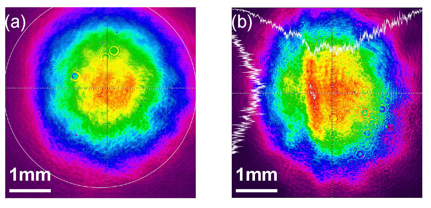
3.1. Optimizing the Coupling of the Trapping Laser Beam
To avoid the spatial inhomogeneity of the FORT along the HC-ARF and minimize the DLS, we optimize the coupling of the trapping laser beam into a quasi-single-mode HC-ARF in this paper.
In previous studies related to the guidance of atoms, the mode-field diameter (MFD) of the HC-PCF is usually 5–42 μm [22,23,24,25]. As the MFD rises, the atomic cloud has a larger interacting region with the trapping laser beam and the guidance efficiency increases. However, the required optical power of the trapping laser beam, corresponding to the large MFD, also increases under the condition of constant trap depth. In addition, to cover the guidance distance of the atomic cloud, the length of the HC-PCF is usually from a few tens to more than a hundred millimeters [22,23,24,25]. Under non-optimal coupling conditions, a small number of higher-order modes are excited inside the HC-PCF and thus cause intensity modulation along the fiber axis [26]. To overcome this problem, a longer HC-PCF can be used as an effective mode filter since higher-order modes usually have much higher transmission loss than fundamental modes [27]. Considering the above conditions, a 7-core HC-ARF is finally used in this paper. The HC-ARF has a core diameter of 27.0 μm, a MFD of 20.0 μm, and a length of 180 mm. As shown in Figure 3b, the near-field mode profile of the HC-ARF in our experiments can be approximated as quasi-single-mode (see previous work for details of the design and simulation results [16]).
Figure 3.
A 7-core hollow-core anti-resonant fiber: (a) microscopic view of the cross-section; (b) the near-field mode profile with magnification. In the pseudo-color image, red and blue colors represent the strongest and weakest optical intensities, respectively.
As shown in Figure 4a, we optimize the coupling of the trapping laser beam into the HC-ARF by adjusting a set of mirrors and an achromatic lens with a focal length of 75 mm. According to the law of Gaussian beam propagation in space, the trapping laser beam leaving from the HC-ARF has a waist of approximately 2 mm after passing through the lens. Figure 4b,c illustrate the far-field mode profiles recorded by a charge-coupled device camera (CCD) during and after the optimization, respectively. Moreover, we evaluate the optimization of the coupling by the overlap integral factor [28,29] between the far-field mode and a standard Gaussian mode with an MFD of 4 mm. The overlap integral factors in Figure 4b,c are 0.948 and 0.986, respectively.
Figure 4.
Far-field mode profiles: (a) the setup of the HC-ARF coupling scheme; (b) the far-field mode profile during the optimization; (c) optimized far-field mode profile captured by the CCD.
3.2. Loading of Atoms into the HC-ARF
The atomic cloud is cooled and trapped from rubidium vapor in 1.0 s by an MOT with an efficiency of . The cooling laser beam is red-detuned from the 87Rb D2 transition, while the repump laser beam is resonant on 87Rb D2 transition. After the gradient magnetic field is turned off, we perform a 25 ms long polarization gradient cooling (PGC). The atomic cloud is further cooled by linearly decreasing the detuning of the cooling laser beam from to and ramping down the optical power of each laser beam from to . Turn off the repump laser beam before the end of the PGC. Then, the cooling laser beams will pump all the 87Rb atoms to the state. The pushing laser beam, resonant on the 87Rb D2 transition, is then used to horizontally heat the remaining atoms in the state. After the process of building, the atomic cloud contains approximately at 5.0 μK with an initial diameter of 1.3 mm in the vertical direction.
After turning off the cooling and repump laser beams in MOT, the atomic cloud is freely released from approximately 2.7 mm above the tip of the HC-ARF. We then turn on the 852 nm trapping laser beam to create a FORT that restricts the movement of atoms. As the atomic cloud expands, many of the atoms are lost. Only a fraction of the atoms that spatially overlap with the trapping laser beam and have temperatures lower than the local FORT are trapped and guided toward the HC-ARF under gravity. As shown in Figure 5a, the darker line indicates the trapped atoms. Since the trapping laser beam is turned on instantaneously, the loading of atoms into the HC-ARF in our experiments is a non-adiabatic process. As the atoms move toward the tip of the HC-ARF, the FORT becomes deeper, resulting in a higher temperature of the atomic cloud. The heating mechanism has been attributed to the transverse compression of the atomic cloud by the funnel-shaped FORT [25] and the intensity modulation from the higher-order modes [26].
Figure 5.
Loading of atoms into the HC-ARF: (a) absorption images of the atomic cloud above the HC-ARF at different loading times t. A coordinate system is established, in which the tip of the HC-ARF is considered as the origin; (b) resonant optical depth versus expansion time . Each data point is an average of five repetitions, and the curve is a fit with Equation (4).
We measure the radial temperature of the atomic cloud inside the HC-ARF using the time-of-flight (TOF) method [15,20], and a typical time sequence is shown in Figure 2b. After a loading time t of about 30.0 ms, all the trapped atoms are loaded into the HC-ARF. The trapping laser beam is then turned off, allowing the atomic cloud to expand freely. After an expansion time , we send the probe laser pulses to measure the optical depth (OD). The resonant optical depth is calculated as [22]
where is the natural linewidth, is the detuning of the probe laser pulse, and I and refer to the optical field intensity and saturation intensity, respectively. As shown in Figure 5b, the dashed line is a fit with an equation as follows [30]:
where represents the Boltzmann constant, is the atomic mass of 87Rb, is the waist of the mode-field diameter inside the HC-ARF, is the optical depth at the center of the HC-ARF when , and U refers to the depth of the FORT. With a trap depth of 100 μK, the radial temperature T of the atomic cloud loaded into the HC-ARF is estimated to be approximately 20 μK. The resonant optical depth when is about 50, corresponding to an atomic number of [22].
3.3. Preparation of Zeeman-Insensitive State
After the process of loading, the 87Rb atoms in the state will be uniformly distributed in three sub-levels with a bias magnetic field of . In this case, the number of atoms in the Zeeman-insensitive state is of the total number of atoms. To increase the population in the Zeeman-insensitive state, we pump 87Rb atoms to the target sub-level using a 10.0 μs long pump laser pulse with an optical power of tens of nanowatts, resonant on 87Rb D2 transition. The propagation direction of the pump laser pulse and the direction of the bias magnetic field are both along the HC-ARF. Therefore, the transitions of the 87Rb atoms driven by the pump laser pulse can be decomposed into and transitions, excluding the transition. Under the transition rules in Figure 6a, the 87Rb atoms in the sub-levels and are pumped to the Zeeman-insensitive state by the transitions, respectively. In addition, the dipole matrix element for the transition is zero [31]. In this case, the 87Rb atoms in the sub-level , regarded as a ‘dark state’, no longer interact with the pump laser pulse. Theoretically, all the 87Rb atoms will eventually be distributed in a Zeeman-insensitive state .
Figure 6.
Optical pumping: (a) Zeeman sub-levels of 87Rb and the transition rules. Red cross indicates that the 87Rb atoms in the sub-level no longer interact with the pump laser pulse; (b) microwave Raman spectra with and without the pump laser pulse. The measured data points are fitted to the sinc functions.
The pumping efficiency is measured by performing a microwave Raman spectrum. After the pump process, a microwave pulse with a magnetic field component parallel to the quantization axis and a Rabi frequency of are applied to pump the atoms from the state to the state. For the estimation of the normalized population of the 87Rb atoms, we send three probe laser pulses into the HC-ARF and detect the transmission of these pulses using an APD. All the probe laser pulses have a detuning of from the 87Rb D2 transition, an optical power of , and a pulse width of 10.0 μs. During the process of detection, the first laser pulse is used to detect the 87Rb atoms in the state. After a repump laser pulse with a pulse width of 5.0 μs, the second laser pulse detects all the 87Rb atoms inside the HC-ARF. As a reference, the third laser pulse detects the optical power after all the 87Rb atoms have been lost. The voltage values , , and converted by the APD correspond to three probe laser pulses, respectively. The normalized population of the 87Rb atoms inside the HC-ARF is calculated as
where and refer to the ODs of the 87Rb atoms in the two detection windows. As shown in Figure 6b, the red and blue dashed lines indicate the microwave Raman spectra with and without the pump laser pulse, respectively. After a pump laser pulse, the peak value of the normalized population increases from about to nearly . Therefore, the pumping efficiency is close to , and the 87Rb atoms in the Zeeman-insensitive state are approximately with a trap depth of 100 μK.
3.4. Atom Interferometer
3.4.1. Raman Laser Pulses
The Raman laser pulses are generated by a tunable diode laser with a one-photon detuning of from 87Rb D2 transition. After modulation by an electro-optic modulator (EOM), the sidebands are produced at 87Rb ground-state hyperfine splitting of . In our experiments, a pair of Raman laser pulses for a two-photon Raman transition consist of the carrier and the -order sideband. However, the -order sideband and carrier also create another two-photon Raman transition with opposite phases. The other higher-order pairs are far-detuned, and their contribution to the effective Rabi frequency is negligible. In this case, the effective Rabi frequency is approximated as [32]
where and refer to Rabi frequencies of the carrier and the -order sideband, respectively. Equation (6) indicates that the effective Rabi frequency of Raman laser pulses in our experiments has a reduction factor of about . In addition, to cancel out the DLS of 87Rb ground-state hyperfine levels introduced by Raman laser pulses, the power ratio between the carrier and the -order sideband is configured as follows [33]:
where refers to the one-photon detuning from the 87Rb D2 transition. According to Equation (7), the power ratio of a pair of Raman laser pulses is finally set to 1.72:1 by adjusting the amplitude of the EOM phase modulation.
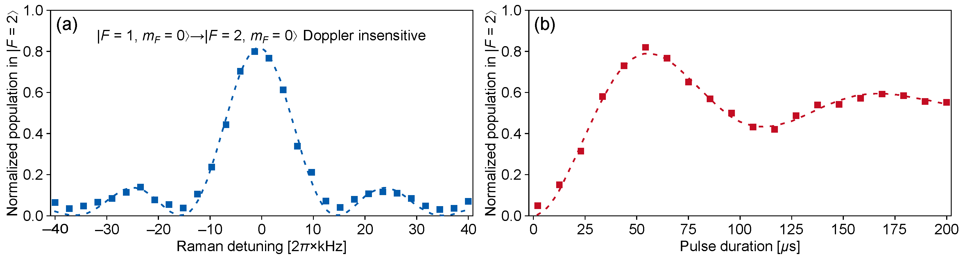
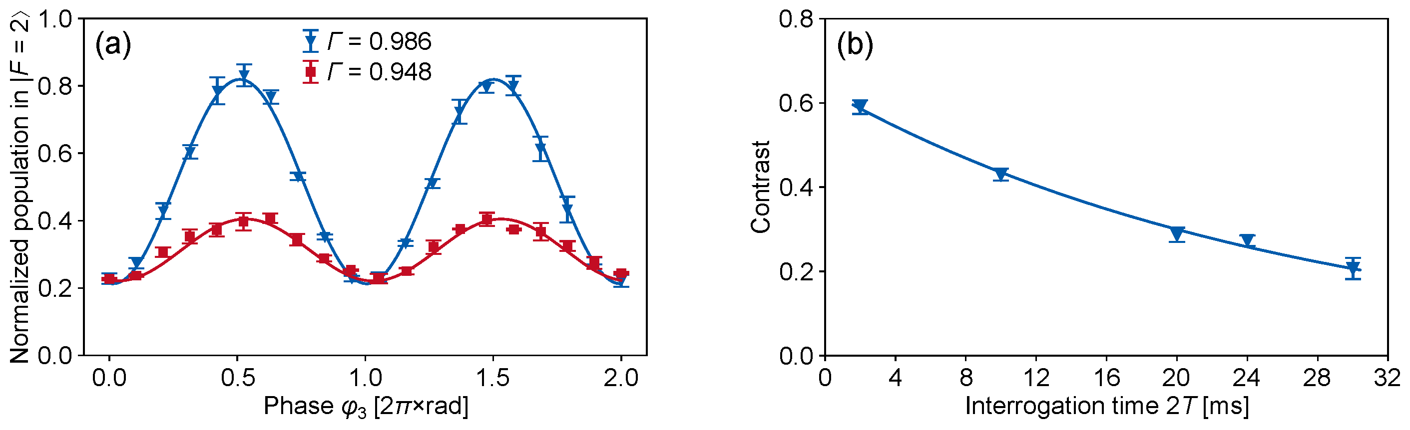
3.4.2. Doppler-Insensitive Interferometry
Prior to demonstrating a tightly trapped atom interferometer inside the HC-ARF, we perform Doppler-insensitive interferometry to show the upper limit of the coherence time in our experiments by implementing a spin-echo sequence. As shown in Figure 7a, the retro-reflection optical path is blocked, and the direction of the Raman laser pulses is co-propagating in Doppler-insensitive interferometry. The polarization of Raman laser pulses is configured as by adjusting the quarter-wave plates in Figure 1a. In this case, the effective wave vector experienced by the 87Rb atoms is , corresponding to a gravity sensitivity about five orders of magnitude lower than that of Doppler-sensitive interferometry.
Figure 7.
Configuration of Raman laser pulses: (a) co-propagating. The polarization is configured as ; (b) counter-propagating. Two pairs of lin ⊥ lin polarized Raman laser pulses (diagonal and antidiagonal).
The efficiency of the co-propagating Raman laser pulses is estimated by performing Raman spectra inside the HC-ARF. Trapped atoms are pumped from the state to the state by a pair of Raman laser pulses with an effective Rabi frequency of . Figure 8a,b illustrate the measured normalized population versus the two-photon Raman detunings and Raman pulse durations, respectively. The blue squares in Figure 8 are fitted to a sinc function. The resonance peak of the fitted line shows a shift of approximately , which corresponds to the average DLS introduced by a 100 μK FORT (see previous work for details [16]). In addition, the red squares in Figure 8 are fitted to a damped sinusoidal function. The maximum efficiency of a pair of co-propagating Raman laser pulses with a pulse width of 54 μs is approximately .
Figure 8.
Doppler-insensitive Raman transition: (a) normalized population versus Raman detunings; (b) normalized population versus pulse durations.
After determining the Rabi frequency and the pulse width of the Raman laser pulses, Doppler-insensitive interferometry is performed inside the HC-ARF. By scanning the phase of the third Raman laser pulses, we observe two Doppler-insensitive interference fringes with interrogation times of in Figure 9a, corresponding to the far-field mode profiles of the trapping laser beam during and after the optimization, respectively. The contrasts, obtained from the fitting results of the measured data points in Figure 9a according to Equation (1), are and , respectively. Under non-optimal coupling conditions, both the trapping and Raman laser beams excite higher-order modes as the and laser beams in this paper are coupled into the HC-ARF through the same PM-SMF and optical paths. The red squares in Figure 9a show that the inhomogeneity of the laser beam mainly leads to an increase in the residual DLS (or additional phase) and a decay in the contrast C of the interference fringe, while the inhomogeneity of the laser beam leads to the inefficiency of the co-propagating Raman laser pulses and a decrease in the amplitude A of the interference fringes. In addition, the blue triangles in Figure 9a suggest that optimizing the coupling of the trapping laser beam is effective in suppressing the DLS caused by the spatial inhomogeneity of the FORT along the fiber.
Figure 9.
Doppler-insensitive interferometry inside the HC-ARF: (a) interference fringes with interrogation times of . The red squares and blue triangles correspond to the far-field mode profiles of the trapping laser beam during and after the optimization, respectively. Each data point is an average of three repetitions with the standard deviation; (b) contrast versus interrogation times under the condition of optimal coupling. Each data point corresponds to an average of three fitting results from the interference fringes, and the curve is a fit with an exponential decay function [see Equation (8)].
To estimate the coherence time , we further measure Doppler-insensitive interference fringes with different interrogation times under the condition of optimal coupling. It is difficult to decouple the residual DLS, the inhomogeneity of the second-order Zeeman shift along the HC-ARF, the intensity fluctuations of the trapping laser beam, and the vibration noise from the laboratory, which cause the decoherence of a Doppler-insensitive interferometry inside the HC-ARF. In this case, we fit the contrast regarding the interference fringe in Figure 9b by the usual exponential decay as the interrogation times increase:
where the coherence time is defined as the time T for the fitted curve to decay to of the maximum contrast . According to Equation (8), the coherence time of Doppler-insensitive interferometry with a FORT is about , corresponding to interrogation times of . In contrast, the coherence time of the atomic cloud in a microwave Ramsey sequence is less than with the same trap depth of 100 μK (see previous work for details [16]). The experimental results indicate that the inhomogeneous dephasing introduced by the DLS has been effectively reversed in a spin-echo sequence by optimizing the coupling of the trapping laser beam into a quasi-single-mode HC-ARF. In future work, we plan to monitor and stabilize the optical power of the trapping laser beam, replace a uniform bias magnetic field, and use a vibration isolation platform to further extend the upper limit of the coherence time in our experiments.
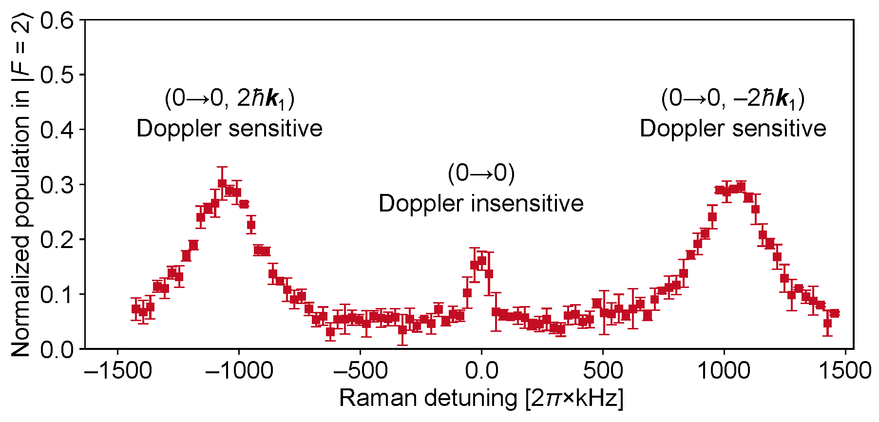
3.4.3. Doppler-Sensitive Interferometry
Unlike Doppler-insensitive interferometry, the polarization in Doppler-sensitive interferometry is configured as lin ⊥ lin and the direction of Raman laser pulses is counter-propagating, corresponding to an effective wave vector of (). As shown in Figure 1a, the transmission of NPBS and the re-coupling efficiency of the Raman laser pulse are approximately and , respectively. Therefore, the retro-reflection optical path in our experiments results in an attenuation factor of approximately on the optical power of the incident Raman laser pulse. The counter-propagating Raman spectrum of the 87Rb atoms inside HC-ARF is measured by scanning the two-photon Raman detunings of the Raman laser pulses with a pulse width of 10.0 μs. Since the polarization extinction ratio of the counter-propagating Raman laser pulses in our experiments is only about , one Doppler-insensitive resonance peak with a line width of about , which ideally should not exist, can still be observed in Figure 10. As the 87Rb atoms fall along the HC-ARF, the two Doppler-sensitive resonance peaks in the Raman spectrum exhibit opposite shifts, which correspond to the two pairs of counter-propagating Raman laser pulses (diagonal and antidiagonal) in Figure 7b, respectively. At a loading time of t, the Doppler shift between two Doppler-sensitive resonance peaks is calculated as follows:
where represents the center velocity of the atomic cloud. According to Equation (9), the center velocity of the atomic cloud along the HC-ARF at a loading time of is about . The axial velocity distribution of the atomic cloud inside the HC-ARF introduces Doppler broadening to the counter-propagating resonance peak, resulting in a broadened full width at half maximum (FWHM) of approximately .
Figure 10.
Doppler broadening of Raman transition due to the axial velocity distribution. The error bars are the standard deviation of the average of three experimental runs.
We then perform Doppler-sensitive interferometry inside the HC-ARF by scanning the phase of the third Raman laser pulses. Figure 11a shows the Doppler-sensitive interference fringes with different pulse widths . Due to Doppler broadening, the Raman laser pulses with a pulse width of (red squares) can pump more 87Rb atoms than the Raman laser pulses with a pulse width of (blue triangles). The measured data points of the blue triangles and the red squares are fitted with Equation (1), corresponding to contrasts of and , respectively. As shown in Figure 11b, we perform the same atom interferometry at different positions inside the HC-ARF. During the time interval from 30 to , the movement range of the atoms is approximately according to the kinematic equation. With the increase in the loading time t, the phase offset of the interference fringe remains relatively consistent, although the contrast gradually decreases. We also plot Doppler-sensitive interference fringes with different trap depths in Figure 11c. As the dipole trap becomes shallower, the contrast regarding the interference fringes increases due to the decrease in the DLS introduced by the FORT [20] and the lower temperature of the atomic cloud inside the HC-ARF [22].
Figure 11.
Doppler-sensitive interference fringes: (a) with different pulse widths , and interrogation times . The error bars are the standard deviation of the average of three repetitions; (b) at different loading times t. The interrogation times are , and the trap depth is . The error bars represent the standard deviation of three experimental runs; (c) with different depths U. The interrogation times are , and the loading time is . Each data point is an average of three repetitions with the standard deviation.
To fit the coherence time , we measure Doppler-sensitive interference fringes with different interrogation times . Figure 12a illustrates the contrast versus interrogation times under the condition of a pulse width . The coherence time, estimated from the damped curve, is about . Compared to the Doppler-insensitive interferometry, the coherence time of the Doppler-sensitive interferometry is reduced by a factor of several hundred when using the same trap depth of . This indicates that the contrast regarding the Doppler-sensitive interference fringes in our experiments is not mainly limited by the residual DLS caused by the trapping laser beam.
Figure 12.
Doppler-sensitive interferometry inside the HC-ARF: (a) contrast versus interrogation times . Each data point corresponds to an average of three fitting results from the interference fringes, and the damped curve is a fit with Equation (8); (b) interference fringes with different Doppler shifts. The contrasts of the blue triangles, red squares, and green dots are , , and , respectively.
We attribute the decay in the contrast to the inefficiency of the counter-propagating Raman laser pulses. One reason for the inefficiency is the wide axial velocity distribution (or the high axial temperature) of the atomic cloud. In a three-pulse Mach–Zender interferometer, the normalized population in state is calculated as follows [34]:
where and represent the probability amplitude that the atom is in the and states at time t, respectively. M denotes the matrix corresponding to Raman laser pulses:
where is the Raman laser pulse duration, is the phase of the Raman laser pulse, is the two-photon Raman detuning due to the Doppler shift, and the axial velocity v is Gaussian-distributed. and refer to the effective Rabi frequency and the generalized Rabi frequency, respectively. To demonstrate that the axial velocity distribution is a main obstacle to improving the coherence time, we numerically calculated the Doppler-sensitive interference fringes corresponding to different Doppler shifts according to Equations (10) and (11). The probability amplitudes of the atoms in the state before the three-pulse Raman laser are and , respectively. A Raman laser pulse has a pulse width of , and the interrogation times are . We then plot the integration results in Figure 12b by scanning the phase of the last Raman laser pulses. The Doppler broadening values of the blue triangles, red squares, and green dots in Figure 12b are , , and , corresponding to contrasts of , , and , respectively. The results of the theoretical calculations illustrate that a wide axial velocity distribution leads to the smearing of the Doppler-sensitive interference fringes.
Another reason for the inefficiency includes the irregular modes of the counter-propagating Raman laser pulses along the HC-ARF. The current setup is designed to optimize the coupling of the laser beam. Under non-optimal conditions, a small number of higher-order modes are excited when the laser beams are coupled from the bottom into the HC-ARF, as shown in Figure 13a. Moreover, more higher-order modes inside the HC-ARF can be observed after re-coupling the laser beams from the top to bottom, as shown in Figure 13b. In this case, the counter-propagating Raman laser pulses cannot produce a constant effective Rabi frequency for the 87Rb atoms.
Figure 13.
The irregular far-field mode profiles of Raman laser pulses: (a) coupling into the HC-ARF from the bottom; (b) re-coupling from the top to bottom.
4. Conclusions
In conclusion, we have demonstrated a tightly trapped atom interferometer inside the HC-ARF. By optimizing the coupling of the trapping laser beam into a quasi-single-mode HC-ARF, the inhomogeneous dephasing introduced by the DLS is effectively reversed. This optimization results in a coherence time of in Doppler-insensitive interferometry with a FORT. The significant decay regarding the contrast in the Doppler-sensitive interferometry is primarily attributed to the inhomogeneity of the Raman laser pulses. This issue can be further solved by replacing the HC-ARF with a strong suppression of the higher-order modes [27,35] and employing an achromatic coupling setup for multi-wavelength circumstances. We also expect to suppress the Doppler broadening and improve the efficiency of the Raman laser pulses by atomic velocity selection [36,37] or Raman sideband cooling for tightly trapped atoms [5,38]. Our long-term goal is to enhance the performance of the tightly trapped atom interferometer inside the HC-ARF to the level of Doppler-insensitive interferometry. This would result in an inertial sensitivity (fundamentally limited by the atom shot noise ) of approximately with atoms, interrogation times, and a contrast of . Our work establishes an important step towards a fiber-guided atom interferometer that has the potential for inertial sensing at arbitrary orientations and in dynamic environments such as space, airborne, shipborne, and underwater.
Author Contributions
Conceptualization, W.L. and Y.S.; methodology, W.L. and Y.S.; investigation, Y.S. and W.L.; data curation, Y.S., C.G. and C.D.; writing—original draft preparation, Y.S.; writing—review and editing, W.L.; visualization, Y.S., W.L. and R.H.; supervision, N.S., X.X. and W.L.; project administration, N.S., X.X. and W.L.; funding acquisition, N.S. and W.L. All authors have read and agreed to the published version of the manuscript.
Funding
This research was supported by China National Postdoctoral Program for Innovative Talents (BX2021028).
Institutional Review Board Statement
Not applicable.
Informed Consent Statement
Not applicable.
Data Availability Statement
Data underlying the results presented in this paper are not publicly available at this time but may be obtained from the authors upon reasonable request.
Acknowledgments
The authors would like to thank Fei Yu from Shanghai Institute of Optics and Fine Mechanics, Chinese Academy of Sciences for providing the HC-ARF samples.
Conflicts of Interest
The authors declare no conflicts of interest.
References
- Russell, P. Photonic Crystal Fibers. Science 2003, 299, 358–362. [Google Scholar] [CrossRef] [PubMed]
- Poletti, F. Nested Antiresonant Nodeless Hollow Core Fiber. Opt. Express 2014, 22, 23807. [Google Scholar] [CrossRef] [PubMed]
- Debord, B.; Amsanpally, A.; Chafer, M.; Baz, A.; Maurel, M.; Blondy, J.M.; Hugonnot, E.; Scol, F.; Vincetti, L.; Gérôme, F.; et al. Ultralow Transmission Loss in Inhibited-Coupling Guiding Hollow Fibers. Optica 2017, 4, 209. [Google Scholar] [CrossRef]
- Sakr, H.; Chen, Y.; Jasion, G.T.; Bradley, T.D.; Hayes, J.R.; Mulvad, H.C.H.; Davidson, I.A.; Numkam Fokoua, E.; Poletti, F. Hollow Core Optical Fibres with Comparable Attenuation to Silica Fibres between 600 and 1100 nm. Nat. Commun. 2020, 11, 6030. [Google Scholar] [CrossRef] [PubMed]
- Okaba, S.; Takano, T.; Benabid, F.; Bradley, T.; Vincetti, L.; Maizelis, Z.; Yampol’skii, V.; Nori, F.; Katori, H. Lamb-Dicke Spectroscopy of Atoms in a Hollow-Core Photonic Crystal Fibre. Nat. Commun. 2014, 5, 4096. [Google Scholar] [CrossRef]
- Epple, G.; Kleinbach, K.S.; Euser, T.G.; Joly, N.Y.; Pfau, T.; Russell, P.S.J.; Löw, R. Rydberg Atoms in Hollow-Core Photonic Crystal Fibres. Nat. Commun. 2014, 5, 4132. [Google Scholar] [CrossRef]
- Langbecker, M.; Noaman, M.; Kjærgaard, N.; Benabid, F.; Windpassinger, P. Rydberg Excitation of Cold Atoms inside a Hollow-Core Fiber. Phys. Rev. A 2017, 96, 041402. [Google Scholar] [CrossRef]
- Sprague, M.R.; Michelberger, P.S.; Champion, T.F.M.; England, D.G.; Nunn, J.; Jin, X.M.; Kolthammer, W.S.; Abdolvand, A.; Russell, P.S.J.; Walmsley, I.A. Broadband Single-Photon-Level Memory in a Hollow-Core Photonic Crystal Fibre. Nat. Photonics 2014, 8, 287–291. [Google Scholar] [CrossRef]
- Li, W.; Islam, P.; Windpassinger, P. Controlled Transport of Stored Light. Phys. Rev. Lett. 2020, 125, 150501. [Google Scholar] [CrossRef]
- Venkataraman, V.; Saha, K.; Gaeta, A.L. Phase Modulation at the Few-Photon Level for Weak-Nonlinearity-Based Quantum Computing. Nat. Photonics 2013, 7, 138–141. [Google Scholar] [CrossRef]
- Hu, Z.K.; Sun, B.L.; Duan, X.C.; Zhou, M.K.; Chen, L.L.; Zhan, S.; Zhang, Q.Z.; Luo, J. Demonstration of an Ultrahigh-Sensitivity Atom-Interferometry Absolute Gravimeter. Phys. Rev. A 2013, 88, 043610. [Google Scholar] [CrossRef]
- Fu, Z.; Wang, Q.; Wang, Z.; Wu, B.; Cheng, B.; Lin, Q. Participation in the Absolute Gravity Comparison with a Compact Cold Atom Gravimeter. Chin. Opt. Lett. 2019, 17, 011204. [Google Scholar] [CrossRef]
- Yoon, T.; Bajcsy, M. Laser-Cooled Cesium Atoms Confined with a Magic-Wavelength Dipole Trap inside a Hollow-Core Photonic-Bandgap Fiber. Phys. Rev. A 2019, 99, 023415. [Google Scholar] [CrossRef]
- Schrader, D.; Kuhr, S.; Alt, W.; Müller, M.; Gomer, V.; Meschede, D. An Optical Conveyor Belt for Single Neutral Atoms. Appl. Phys. B 2001, 73, 819–824. [Google Scholar] [CrossRef]
- Xin, M.; Leong, W.S.; Chen, Z.; Lan, S.Y. An Atom Interferometer inside a Hollow-Core Photonic Crystal Fiber. Sci. Adv. 2018, 4, e1701723. [Google Scholar] [CrossRef] [PubMed]
- Song, Y.; Li, W.; Xu, X.; Han, R.; Gao, C.; Dai, C.; Song, N. Suppressing the Dephasing of Optically Trapped Atoms inside a Hollow-Core Fiber. Opt. Lett. 2024, 49, 206. [Google Scholar] [CrossRef] [PubMed]
- Kaplan, A.; Fredslund Andersen, M.; Davidson, N. Suppression of Inhomogeneous Broadening in Rf Spectroscopy of Optically Trapped Atoms. Phys. Rev. A 2002, 66, 045401. [Google Scholar] [CrossRef]
- Carr, A.W.; Saffman, M. Doubly Magic Optical Trapping for Cs Atom Hyperfine Clock Transitions. Phys. Rev. Lett. 2016, 117, 150801. [Google Scholar] [CrossRef] [PubMed]
- Xin, M.; Leong, W.S.; Chen, Z.; Lan, S.Y. Transporting Long-Lived Quantum Spin Coherence in a Photonic Crystal Fiber. Phys. Rev. Lett. 2019, 122, 163901. [Google Scholar] [CrossRef]
- Wang, Y.; Chai, S.; Billotte, T.; Chen, Z.; Xin, M.; Leong, W.S.; Amrani, F.; Debord, B.; Benabid, F.; Lan, S.Y. Enhancing Fiber Atom Interferometer by In-Fiber Laser Cooling. Phys. Rev. Res. 2022, 4, L022058. [Google Scholar] [CrossRef]
- Kuhr, S.; Alt, W.; Schrader, D.; Dotsenko, I.; Miroshnychenko, Y.; Rauschenbeutel, A.; Meschede, D. Analysis of Dephasing Mechanisms in a Standing-Wave Dipole Trap. Phys. Rev. A 2005, 72, 023406. [Google Scholar] [CrossRef]
- Bajcsy, M.; Hofferberth, S.; Peyronel, T.; Balic, V.; Liang, Q.; Zibrov, A.S.; Vuletic, V.; Lukin, M.D. Laser-Cooled Atoms inside a Hollow-Core Photonic-Crystal Fiber. Phys. Rev. A 2011, 83, 063830. [Google Scholar] [CrossRef]
- Vorrath, S.; Möller, S.A.; Windpassinger, P.; Bongs, K.; Sengstock, K. Efficient Guiding of Cold Atoms through a Photonic Band Gap Fiber. New J. Phys. 2010, 12, 123015. [Google Scholar] [CrossRef]
- Hilton, A.; Perrella, C.; Benabid, F.; Sparkes, B.; Luiten, A.; Light, P. High-Efficiency Cold-Atom Transport into a Waveguide Trap. Phys. Rev. Appl. 2018, 10, 044034. [Google Scholar] [CrossRef]
- Langbecker, M.; Wirtz, R.; Knoch, F.; Noaman, M.; Speck, T.; Windpassinger, P. Highly Controlled Optical Transport of Cold Atoms into a Hollow-Core Fiber. New J. Phys. 2018, 20, 083038. [Google Scholar] [CrossRef]
- Wang, Y.; Chai, S.; Xin, M.; Leong, W.S.; Chen, Z.; Lan, S.Y. Loading Dynamics of Cold Atoms into a Hollow-Core Photonic Crystal Fiber. Fibers 2020, 8, 28. [Google Scholar] [CrossRef]
- Uebel, P.; Günendi, M.C.; Frosz, M.H.; Ahmed, G.; Edavalath, N.N.; Ménard, J.M.; Russell, P.S. Broadband Robustly Single-Mode Hollow-Core PCF by Resonant Filtering of Higher-Order Modes. Opt. Lett. 2016, 41, 1961. [Google Scholar] [CrossRef] [PubMed]
- Wu, Y.K.; Wang, W.S. Design and Fabrication of Sidewalls-Extended Electrode Configuration for Ridged Lithium Niobate Electrooptical Modulator. J. Light. Technol. 2008, 26, 286–290. [Google Scholar] [CrossRef]
- Li, J.-Y.; Lu, D.-F.; Qi, Z.-M. Analyses of Wavelength Dependence of the Electro-Optic Overlap Integral Factor for LiNbO3 Channel Waveguides. Acta Phys. Sin. 2014, 63, 077801. [Google Scholar]
- Song, Y.; Li, W.; Xu, X.; Gao, F.; Song, N. Cold Atoms Guidance into Anti-Resonant Hollow-Core Fibers. Chin. J. Sci. Instrum. 2023, 44, 127–134. [Google Scholar]
- Steck, D.A. Rubidium 87 D Line Data. 2023. Available online: https://steck.us/alkalidata (accessed on 26 April 2024).
- Dotsenko, I.; Alt, W.; Kuhr, S.; Schrader, D.; Müller, M.; Miroshnychenko, Y.; Gomer, V.; Rauschenbeutel, A.; Meschede, D. Application of Electro-Optically Generated Light Fields for Raman Spectroscopy of Trapped Cesium Atoms. Appl. Phys. B 2004, 78, 711–717. [Google Scholar] [CrossRef]
- Wu, X.; Zi, F.; Dudley, J.; Bilotta, R.J.; Canoza, P.; Müller, H. Multiaxis Atom Interferometry with a Single-Diode Laser and a Pyramidal Magneto-Optical Trap. Optica 2017, 4, 1545. [Google Scholar] [CrossRef]
- Moler, K.; Weiss, D.S.; Kasevich, M.; Chu, S. Theoretical Analysis of Velocity-Selective Raman Transitions. Phys. Rev. A 1992, 45, 342–348. [Google Scholar] [CrossRef] [PubMed]
- Habib, M.S.; Antonio-Lopez, J.E.; Markos, C.; Schülzgen, A.; Amezcua-Correa, R. Single-Mode, Low Loss Hollow-Core Anti-Resonant Fiber Designs. Opt. Express 2019, 27, 3824. [Google Scholar] [CrossRef] [PubMed]
- Kasevich, M.; Weiss, D.S.; Riis, E.; Moler, K.; Kasapi, S.; Chu, S. Atomic Velocity Selection Using Stimulated Raman Transitions. Phys. Rev. Lett. 1991, 66, 2297–2300. [Google Scholar] [CrossRef] [PubMed]
- He, M.; Chen, X.; Fang, J.; Chen, Q.; Sun, H.; Wang, Y.; Zhong, J.; Zhou, L.; He, C.; Li, J.; et al. The Space Cold Atom Interferometer for Testing the Equivalence Principle in the China Space Station. NPJ Microgravity 2023, 9, 58. [Google Scholar] [CrossRef]
- Leong, W.S.; Xin, M.; Chen, Z.; Chai, S.; Wang, Y.; Lan, S.Y. Large Array of Schrödinger Cat States Facilitated by an Optical Waveguide. Nat. Commun. 2020, 11, 5295. [Google Scholar] [CrossRef]
Disclaimer/Publisher’s Note: The statements, opinions and data contained in all publications are solely those of the individual author(s) and contributor(s) and not of MDPI and/or the editor(s). MDPI and/or the editor(s) disclaim responsibility for any injury to people or property resulting from any ideas, methods, instructions or products referred to in the content. |
© 2024 by the authors. Licensee MDPI, Basel, Switzerland. This article is an open access article distributed under the terms and conditions of the Creative Commons Attribution (CC BY) license (https://creativecommons.org/licenses/by/4.0/).