Abstract
A comprehensive energy and exergoeconomic analysis of a novel transcritical refrigeration cycle (NTRC) is presented. A second ejector is introduced into the conventional refrigeration system for the utilization of the gas-cooler waste heat. The thermodynamic properties of the working fluid are estimated by the database of REFPROP 9, and a FORTRAN program is used to solve the system governing equations. Exergy, energy, and exergoeconomic analyses of the two cycles are carried out to predict the exergetic destruction rate and efficiency of the systems. The optimum gas cooler working pressure will be determined for both cycles. A comprehensive comparison is made between the obtained results of the conventional and the new cycles. An enhancement of approximately 30% in the coefficient of performance (COP) of the new cycle was found in comparison to the value of the conventional cycle. In addition, the results of the analysis indicated a reduction in the overall exergy destruction rate and the total cost of the final product by 22.25% and 6%, respectively. The final product cost of the proposed NTRC was found to be 6% less than that of the conventional ejector refrigeration cycle (CERC), whereas the optimum value of the gas cooler pressure was 10.8 MPa, and 11.4 MPa for the NTRC and CERC, respectively.
1. Introduction
The International Energy Agency considers the Middle East region as one of the fastest-growing regions for energy demand over the period 2006–2030. Additionally, a profound increase in energy demand and economic growth has been experienced in the Middle East region, and it has been an exciting subject for researchers to investigate. It is estimated that 65% of the total energy produced is consumed by air conditioning (AC) applications in this region, due to hot climates [1]. In hot climates, the environmental conditions are the main challenge for AC and refrigeration units. Higher ambient temperatures lead to an increase in the condensation pressure, and that causes higher electrical consumption [2].
According to Salahuddin and Gow [3], a relationship exists between carbon dioxide (CO2) emission and energy consumption for long and short terms. Therefore, utilizing a natural refrigerant for refrigeration has been the focus of research and development to replace the environmentally non-friendly refrigerants Chlorofluorocarbon (CFC) and hydrofluorocarbon (HFC), which have high global warming potential (GWP).
CO2 is an excellent alternative refrigerant, which enables the reduction of negative impact on the GWP. It is a natural fluid, non-flammable, inexpensive, non-toxic, and offers advantageous thermophysical and transport properties, and has zero ozone depletion potential (ODP) with GWP = 1. A propane mechanical subcooling system with a two-stage transcritical carbon dioxide refrigerating machine was studied to evaluate the best system coefficient of performance (COP) for different subcooling systems [4,5].
The properties of CO2 are unique, with a low critical temperature of 31.2 °C. Kauf [6] thermodynamically analyzed a CO2 refrigeration system and presented correlations of the system optimum values at high pressure. More detailed correlations were found for refrigeration systems without and with internal heat exchangers [7,8]. Later, refrigeration systems with internal heat exchangers were experimentally studied, and an enhancement of 10% in the COP of the system was found [9,10,11]. Transcritical carbon dioxide refrigeration systems with multiple ejectors were thermodynamically investigated. Some disadvantages of the carbon dioxide refrigeration cycles were reported when high pressure and temperature conditions prevailed, which led to a decrease in the system performance. New technologies and modifications of the cycle were implemented to overcome these drawbacks and enhance the cycle energy efficiency and system performance. The Rankine power cycle was integrated into the ejector cooling cycle, and the new system was mathematically analyzed to evaluate the effect of major parameters on the performance of the system [12,13].
A thermodynamic analysis of a CO2 conventional refrigeration system and R134a as working fluids was conducted. The results showed that CO2 presents a lower performance in comparison to R134a [14,15]. Thermodynamic analysis of a transcritical refrigeration cycle with CO2 and ethane as the working fluids were investigated. The results showed the superiority of ethane over carbon dioxide in terms of second law efficiency and compressor discharge temperature [16]. New arrangements of refrigeration cycles that utilize low-grade heat sources such as solar energy were investigated and studied [17,18,19,20].
Several working fluids were investigated and studied as the best replacement in refrigeration cycles based on their environmental impact and characteristics performance [21,22,23]. Different combinations of transcritical refrigeration cycles with carbon dioxide as the working fluid were studied [24,25,26].
Sarkar and Agrawal [27] proposed different configurations of parallel compression, which resulted in an enhancement of 47% of COP in the conditions of a high-temperature difference between the condenser and the evaporator. Another two-stage refrigeration transcritical CO2 cycle was presented, and an 80% improvement in the system COP was registered in comparison with the conventional system [28]. Furthermore, the implementation of parallel compression systems was found of great value in refrigeration systems, and an enhancement of 30% in the COP was found in comparison with the normal cycle [29,30].
Megdouli et al. [31] found that for improving the COP, the most efficient method is the use of the waste heat in the gas cooler (GC), with a 12% enhancement in the system COP. A thermo-economic investigation was conducted to study the operating parameters’ effects in a new power and cooling system. The results found a highly efficient system in comparison with the already existing combined systems [32]. Fazelpour and Morosuk [33] showed that the use of an economizer led to a 4–5% increase in the equipment purchased cost and a decrease in the final product total cost by 13–14%.
The economic and configuration optimization of the combined cycles were extensively studied in the literature. It was deduced that several combined heating, cooling, and power generation systems with low-grade heat source were efficient [34,35,36,37]. The use of ejector in cooling systems has been extensively studied over the past decade. New refrigerants were proposed to achieve higher system COP and advance the technology of ejector cooling systems to be compact and efficient. New refrigeration cycles with the combination of ejector and Rankine cycle for the combined cooling and power generation had been investigated. Researchers found that the use of the ejector decreased the power consumed by the compressor and enhanced the system COP. The exergetic efficiency was found to be increased by 155% for the combined cycle with the ejector [38,39].
It is a well-known fact that any throttling valve operates as an isenthalpic device. Such a thermodynamic process causes a reduction in the refrigerating effect since the refrigerant kinetic energy generated by the pressure drop is converted into friction. An ejector, which is cheap, able to handle the two-phase flow, and has no moving parts, is used to recover part of energy content. An enhancement of 26% in the cycle COP could be achieved when utilizing the ejector [40,41].
It was concluded that the transcritical refrigeration cycle with ejector had better performance than that of parallel compression in industrial applications. A one-dimensional model of a constant pressure mixing ejector in which the conventional components performed ideally was implemented in several research works [42,43,44,45]. The outcomes underlined that the diffuser efficiency has the most substantial influence on the increase in COP. Furthermore, an optimal mixing pressure, which can be ascribed to a tradeoff between the mixing process irreversibilities and the inefficiencies occurring in the nozzle and the diffuser, has to be identified [46]. Bilir and Ersoy [47] claimed that this technology could perform much better for refrigerating plants in hot climates. High potentials of enhancement could be attained on the part of a transcritical ejector refrigeration cycle operating at high outdoor temperatures. Enhanced ejector technology was recently developed and utilized in engineering applications with transcritical refrigeration cycle to enhance its performance characteristics [48,49].
The literature review highlighted the existence of different strategies for the improvement of the CO2 transcritical cycle performance. Different types and configurations of air conditioning and refrigeration systems are used in industrial, residential, and commercial applications to maintain comfort conditions. In the case of the application of these systems in places and areas without reliable power supply, the low-grade heat source can be utilized in refrigerating machines, which makes them promising technologies. In addition, the utilization of the cycle waste heat had gained the interest of researchers over the past decades. The introduction of the ejector into the transcritical cycle had been proved to be an excellent approach to harvest low grade heat and enhance the cycle performance. Therefore, the present study introduces the design of a novel transcritical refrigeration cycle (NTRC) with an ejector. The governing equations are solved using a FORTRAN program, and the code is validated by experimentally obtained and published data. A comprehensive comparison of energy and exergy parameters is conducted for the conventional ejector refrigeration cycle (CERC) and the NTRC. The waste energy rejected by the GC in the ejector expansion refrigeration cycle is utilized as the driving source heat temperature for the ejectors. A thermo-economical study will be carried out to evaluate the performance of both cycles. The simulation results of the new proposed cycle will be compared with those of the CERC operating at the same conditions and cooling capacity. The optimum gas cooler working pressure will be determined for the cycles. The exergy, energy, and exergoeconomic analysis of the systems are conducted using a FORTRAN program with the REFPROP database for the working fluid properties.
2. The Description of the Cycles
The components of the CERC, as shown in Figure 1, are a compressor, a separator, an expansion valve, a GC, an evaporator, and an ejector. The working refrigerant splits into saturated vapor (state 5), and saturated liquid (state 6) in the phase separator. The compressor raises the saturated vapor pressure to (state 2), and then its temperature is reduced to state 3 in the GC. Due to the significant pressure drop, at the converging-diverging nozzle exit in the ejector, the refrigerant vapor is liquefied at (state n). The low-pressure flow creates a vacuum effect that forces the refrigerant vapor to be entrained from the evaporator (state 1). The mixed flow passes through the diffuser section of the ejector with a pressure buildup at the ejector exit (state 4). A cooling effect is generated in the evaporator during the phase change of refrigerant from liquid to saturated vapor (state 7). The refrigerant, at a two-phase state, leaves the ejector and enters the separator. In this way, the CERC is completed. The vapor leaves the compressor at high temperature and pressure and is discharged to the GC, and a cooling process of the refrigerant takes place in the GC.
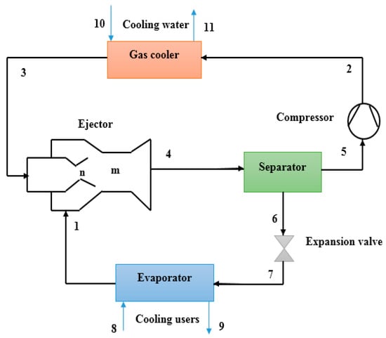
Figure 1.
Schematic of the conventional ejector refrigeration cycle (CERC).
The transcritical ejector expansion refrigeration system is combined with an ERC to utilize the wasted energy in the GC, which will improve the system performance. The NTRC p-h and schematic diagrams are shown in Figure 2.
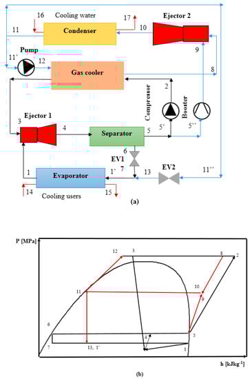
Figure 2.
(a) Novel transcritical refrigeration cycle (NTRC) schematic diagram, (b) NTRC P-h diagram.
The processes of NTRC are described by selecting a starting point and returning to this point in the system. The compressed high-temperature CO2 refrigerant, at state 2, is discharged to the GC, and it exists at state 3 and passes through the first ejector’s nozzle, where it accelerates and creates a low-pressure region that will entrain the evaporator vapor (state 1). The total flow exits the ejector diffuser (state 4) and, later, it leaves the ejector to the separator, where it is split into two saturation states; liquid (state 6) and vapor (state 5). The refrigerant saturated liquid passes through an expansion device and reaches low pressure in the evaporator (state 7), and the compressor compresses the refrigerant vapor to the condenser pressure.
The dissipated heat by the GC is supplied to the refrigerant, which enters and leaves at superheated state conditions (states 12 and 8, respectively). The refrigerant at superheated conditions enters the second ejector’s nozzle as a primary flow, and it gains more speed in the converging-diverging nozzle and thus creating a suction effect at state 9. A booster raises the refrigerant pressure from state 5″ to state 9. The high-pressure flow is mixed with the entrained refrigerant and continues to the ejector’s diffuser section, where the velocity is reduced, and pressure is increased (state 10). The working fluid refrigerant condenses to a liquid at state 11 in the condenser, and the liquid refrigerant splits into two parts; the first one is pumped back to state 11′, and the second stream enters the expansion valve (EV2) through an isenthalpic process to state 11′’. In this configuration, additional cooling capacity is provided, and the system performance is improved.
3. System Mathematical Modeling
The proposed systems are analyzed under the following assumptions:
- The flow in the cycle is frictionless.
- The ejector process is adiabatic.
- The losses in the ejector sections are accounted for by their efficiencies [32], as listed in Table 1.
 Table 1. The reference parameters and operating conditions of the cycle’s performance analysis.
 - The drop in the secondary flow pressure in the ejector nozzle (P1 − Pm) is assumed 0.3 bar [32].
- Saturated states of liquid and vapor are assumed at the exit of the evaporator, condenser, and the separator.
- The expansion valve process is isenthalpic.
- The pump and booster isentropic efficiencies are 90% and 85%, respectively [50].
- The isentropic efficiency of the compressor is equal to 0.8 [33].
- The system cooling capacity is 100 kW.
- The GC temperature difference is five degrees (ΔT = T2 − T8) [51].
- The ambient reference conditions are Ta = 25 °C and Pa = 1 bar, respectively [33].
3.1. Ejector Model
The main components of the ejector are the primary nozzle, mixing chamber, and diffuser. The schematic diagram of the constant pressure mixing ejector model used in this analysis is shown in Figure 3. The primary flow enters the nozzle and accelerates with a decrease in the static pressure. The decrease in pressure creates an entrainment effect of the secondary flow from the evaporator. The primary and secondary flows mix in the mixing chamber and continue their way to the diffuser, where a pressure build-up occurs. The stream pressure increases to the backpressure, which is the condenser pressure.
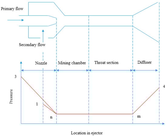
Figure 3.
The ejector schematic with pressure variation.
The ejector’s entrainment ratio is:
where is the secondary mass flowrate, and is the primary flow’s mass flowrate, kg.s−1.
The primary stream velocity is calculated as:
where, —specific isentropic enthalpy, (kJ.kg−1).
The isentropic efficiency of the nozzle is:
The momentum conservation principle is applied to the ejector mixing chamber as follows [52,53]:
where Vm is the exit velocity of the mixed flow, m.s−1.
For the simplicity of analysis, the secondary flow velocity is negligible in comparison to the primary flow velocity, then Vm is evaluated as:
The mixing chamber efficiency is calculated as [53]:
where is the ideal isentropic velocity at the exit of the mixer.
The mixed flow enthalpies are:
The isentropic enthalpy is:
3.2. Energy Analysis
The principle of energy conservation is applied to the cycles’ components, and the equations of the thermodynamic model are derived. The steady mass and energy equations are:
The component’s model equation is presented in Table 2.
Table 2.
Thermodynamic and energy balance equations for CERC and NTRC.
3.3. Exergy Analysis
The main components of the rate of system total exergy () are the physical, kinetic, chemical, and potential exergy rates (, , , ). The magnetic, nuclear, electrical, and other less predominant effects are neglected [54]:
For any closed system, the physical exergy rate is defined in terms of the refrigerant’s entropy and enthalpy differences at a Po and T0:
where h and s are the refrigerant specific enthalpy and entropy.
The system exergy balance equation of each component is [33]:
in which , , and are the rates of exergy of fuel, product, and destruction, respectively.
Exergy loss to the environment is added to the system rate of exergy balance as follows:
The exergy destruction of the system’s component is:
The destruction of exergy ratio is defined as:
The exergy efficiency is:
The equations of system components’ exergy rates of the cycles are shown in Table 3.
Table 3.
Balance equations of the exergy rate of CERC and NTRC.
3.4. The System’s Economical Analysis
In the present work, the total revenue requirement (TRR) method is implemented to carry out the economic analysis of the proposed cycles.
The levelized value of annual CCL is evaluated:
CCL = (the capital total investment) * CRF
CRF is the capital recovery factor defined as:
The interest rate i is 10%, and the lifetime number of years is n = 15 years [33].
The levelized value of annual fuel cost () can be obtained by:
with , where is the operating and maintenance cost rate of escalation ( = 2.5%) [33].
The levelized annual operating and maintenance cost (OMCL) is:
, where is the nominal rate of escalation of the costs of operations and maintenance ( = 2.5%).
, which is the total revenue requirement, is:
The rate of the kth component’s total cost is:
where, and can be calculated as follows:
where; is 6000 h of the system operating at full load per year. denotes the kth component purchased cost. The fuel price is assumed to equal to 0.12 $.kWh−1.
3.5. Exergoeconomic Analysis of the System
The exergoeconomic analysis method used in this work is the specific exergy costing method [55]. The unit cost of exergy, as well as specific components exergy and efficiency with the corresponding auxiliary equations of the energy component system, is applied [33]. The economic analysis is evaluated on the assumptions that the associated costs with the equipment and the installation costs at 15% of the investment capital cost and the purchased equipment cost (PEC) of all expansion devices and that of the receiver were taken from the catalog of the manufacturer at 100 € and 1000 €, respectively [29,33];
The exergoeconomic analysis is a useful tool for studying and evaluating the component’s cost in refrigeration systems. The relationship between the total costs and product cost of the system can be written as follows [33,55]:
The following, Equations (46) and (47), can also be used:
Or
and are the product, and fuel cost rates; and are the product and fuel costs per unit of exergy.
The exergy destruction’ cost rate of a component is:
The relative cost difference and the exergoeconomic factor are:
The total product unit cost can be calculated as:
For comparison purposes, the summations of the total cost rates of exergy destruction and capital investment are used.
where,
The exergoeconomic factor is evaluated as:
The cost balance equations, as well as the corresponding auxiliary equations, are presented in Table 4. A system of linear algebraic equations will result from the application of the balance equations on the system components. The solution of the system is obtained to identify the cost rates and exergy of the system’s components.
Table 4.
Equations of CERC and NTRC cost balance for the analysis.
4. Discussion of Results
4.1. Validation of the Proposed Model and Verification
The governing equations were solved using a FORTRAN computer program is developed for the calculation of the cycle performance. Several iterations were made to converge at a specific value of the entrainment ratio that satisfies the Kornhauser criterion. A comparative analysis is established with the experimental data of the two-phase ejector reported by the published literature [56], and the validation results are presented in Table 5. A good agreement was observed for the proposed model. Furthermore, the computer program and model used for the calculation of the cycle parameters and economic analysis were validated in a previously published work by the authors [26].
Table 5.
Simulation results validation with the published data.
In the published article of Ersoy and Bilir 2010, an ejector model of two-phase flow with the refrigerant R134a as the working fluid, and a constant mixing area type was presented. The operating conditions were the evaporator temperature, Te = −25 °C, and the condenser temperature, Tc = 40 °C. The environmental temperature of 27 °C was adopted as the reference state. A comparison of the values of exergy destruction rates per component, of the present model, was carried out with the theoretically obtained results by Ersoy and Bilir, 2010. The comparison shows an excellent agreement between the results, as shown in Table 6.
Table 6.
Comparison of the exergy destruction rates with published data.
4.2. Energy Results
The thermodynamic calculated values of the properties for the considered cycles are shown in Table 7.
Table 7.
CERC and NTRC points’ properties and rates of cost.
The results of the energetic analysis of the two cycles are presented in Table 8. For comparison purposes, the cooling capacity of both cycles is fixed at 100 kW. The results show that the minimum COP of the CERC is equal to 1.55, while the value of the COP of the NTRC is increased by 29%. This increase in the performance indicates a better performance of the new proposed system in comparison to the conventional cycle from the viewpoint of energy-savings.
Table 8.
CERC and NTRC energy performance characteristics.
4.3. Exergy Results
The results of the exergy analysis of the refrigeration systems with fixed cooling capacity are presented in Figure 4. These results show that the CERC exergy efficiency is 18.17%, while it is higher by 28.9% for the NTRC at a value of 23.4%. Moreover, a reduction in the overall exergy destruction in the NTRC by 22.25% is recorded in comparison to the CERC, as illustrated in Table 9. Figure 4 provided the shares of the components in the overall amount of exergy destruction of the proposed refrigeration cycles.
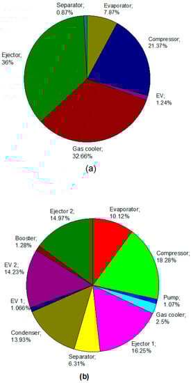
Figure 4.
The cycle components’ contribution to the overall amount of , (a) CERC, (b) NTRC.
Table 9.
CERC and NTRC exergy destruction and efficiency.
Figure 4a illustrates that for the CERC, the highest rate of exergy destruction is in the ejector, the GC, and the compressor, with values of 17.36, 15.77, and 10.32 kW, respectively. These values represent 36%, 32.66%, and 21.37%, respectively, of the CERC overall rate of exergy destruction. Therefore, it is worth investigating to apply new methods to reduce these irreversibilities. Efforts are made to enhance the CERC performance by the reduction of the destruction of exergy in the GC and compressor. The introduction of the proposed NTRC indicates a significant reduction in the exergy destruction rate of the GC and compressor, as shown in Figure 4b. It can be concluded that the proposed NTRC is more favorable given exergy analysis results.
4.4. The Economic Analysis Results
The parameters of the exergoeconomic analysis for different components of the two investigated refrigeration cycles are presented in Table 10. The amount of for the GC in the CERC is 4.31 $.h−1, which is 54.5% of the overall of the CERC. Therefore, the GC component is to be investigated further to achieve better performance of the refrigeration cycles. Besides, the exergoeconomic factor, f, of the GC component is only 6.26%, which indicates the domination of the cost rate of exergy destruction over the capital cost rate.
Table 10.
CERC and NTRC components’ exergoeconomic parameters.
As shown in Table 11, the overall of the NTRC is decreased by 2.2% in comparison to the CERC, while the exergoeconomic factor, f, is higher by 56%. The capital cost of investment is found to be the predominant factor in comparison to the exergy destruction cost. Therefore, cheaper components are to be used in the NTRC. Additionally, for the case of the CERC, the low exergoeconomic factor value shows the profound effect of the cost of exergy destruction on the exergoeconomic performance of the cycle. The final product cost of the proposed NTRC is 6% less than that of the CERC.
Table 11.
CERC and NTRC exergoeconomic results.
4.5. Parametric Sensitivity Analysis
The variation of the cycle parameters profoundly affects the performance of the system. The effect of the variation in some of the cycle parameters on its thermodynamic and exergoeconomic performance is studied. The parameters that are considered in this analysis are Pgc, Tgc, and Te.
4.5.1. The Gas Cooler Pressure Effect
For comparison purposes, the cooling capacity of both cycles is fixed as 100 kW with Tgc, and Te are kept equal to 45 and −15 °C, respectively, and the working fluid is CO2. The best cycle performance is obtained at the optimum Pgc.
The variation of power consumption and the COP of the CERC and NTRC with Pgc are shown in Figure 5. The power consumption decreases and reaches a minimum at a specific value of Pgc. The NTRC consumed about 25% less power compared with the CERC. Besides, a maximum COP of the two cycles was achieved at the corresponding value of Pgc. In the NTRC, the optimum value Pgc is lower than that of the CERC, which is more favorable for system lifetime and safety. It can be noted that the COP of the NTRC and CERC is 2.01 and 1.574, respectively. These values correspond to optimum GC pressure of 10.8 MPa, and 11.4 MPa, for the NTRC and CERC, respectively.
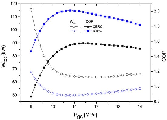
Figure 5.
The coefficient of performance (COP) and power consumption variation with Pgc.
The dependence of the overall rate of exergy destruction and the 2nd law efficiency of NTRC and CERC on Pgc is shown in Figure 6. The minimum exergy destruction rate occurs at Pgc, opt. The 2nd law efficiency shows an increase of 27.7%, and the destruction of the exergy rate is 22% less for the NTRC than that of the CERC.
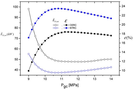
Figure 6.
The 2nd law efficiency , and the overall amount of exergy destruction as a function of Pgc.
It can be concluded that the NTRC has the best energetic and exergetic performance in comparison to the CERC.
The variation of the summation of the exergy destruction and the investment cost rates , the final cost of the product , and the exergoeconomic factor of both cycles with Pgc are shown in Figure 7. According to Figure 7, it is worth noting that in low GC pressure, the overall exergoeconomic factor f of both cycles increases. As Pgc increases above 11 MPa, a constant value of the overall exergoeconomic factor f is maintained. It is noted that it is much lower for the CERC in comparison to that of the NTRC.
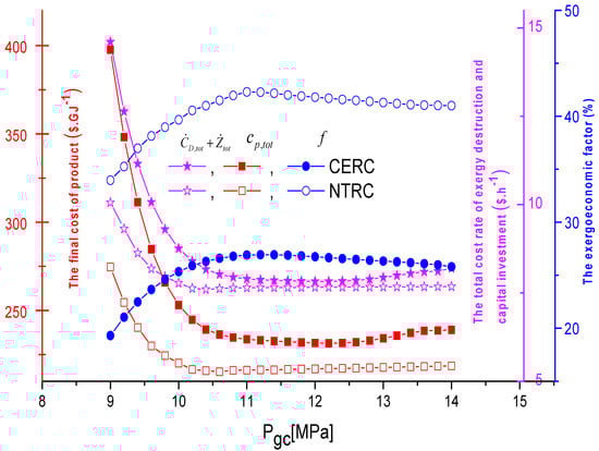
Figure 7.
The exergoeconomic factor, the final cost of the product , and the overall as functions of Pgc.
Besides, the is directly related to the total mechanical work consumption , this means the higher mechanical work consumption leads to higher cost of the product. However, the of NTRC is 7% lower in comparison to the CERC at optimum Pgc.
The Pgc has a profound effect on the cycle performance, and it has been shown that it has an optimum value where the performance has the highest value. Therefore, in the analysis of the effect of other operating parameters, the optimum value of Pgc will be assumed.
4.5.2. Effect of the Exit Temperature in the Gas Cooler
The Tgc effect on the system COP and of both cycles is presented in Figure 8. An increase in power consumption is noticed while Tgc increases, which leads to a decrease in the COP of the system. The NTRC has higher COP values by more than 30% in comparison to the values of the CERC.
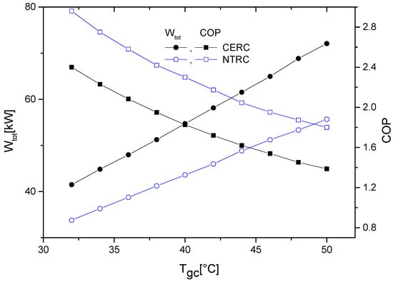
Figure 8.
The COP and Wtot variation as a function of Tgc.
The effect of exit Tgc on the 2nd law efficiency and exergy destruction rate is shown in Figure 9. As Tgc increases, more energy is pertained by the GC. Hence an increase in the destruction rate of exergy is anticipated, as shown in Figure 9, and the NTRC second law efficiency is higher than that for the CERC for the whole range of Tgc.
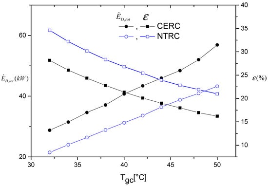
Figure 9.
The second law efficiency and the overall amount of dependence on the exit Tgc.
The variation of the summation of the exergy and capital costs , the exergoeconomic factor f, and the product cost with Tgc is presented in Figure 10. The summation of undergoes an increase as Tgc increases. The increase in for ten degrees increase in Tgc is found to be 30.43% and 17% for the CERC and the NTRC, respectively. Furthermore, increasing Pgc will decrease the exergoeconomic factor of both cycles, showing a higher increase in the exergy destruction cost increases more with Tgc in comparison with the increase in the capital investment cost.
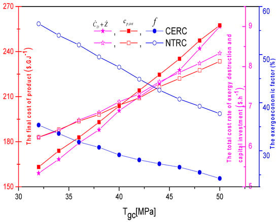
Figure 10.
The exergoeconomic factor, the final cost of the product , and overall dependence on the exit Tgc.
As Tgc increases, the final cost of the product of both cycles increases, which is not a desirable matter.
4.5.3. The Evaporator Temperature Effect on System Performance
The dependence of the COP and on evaporator temperature is shown in Figure 11 for both cycles. The range of evaporator temperature studied is from −30 to 5 °C with Tgc = 45 °C and Pgc = 11 MPa. The increase in the evaporator temperature leads to a decrease in the compressor pressure ratio, and this decrease will result in a power consumption reduction and a cycle COP increase. Besides, the performance of the NTRC is higher than that of the CERC by an average of 23%.
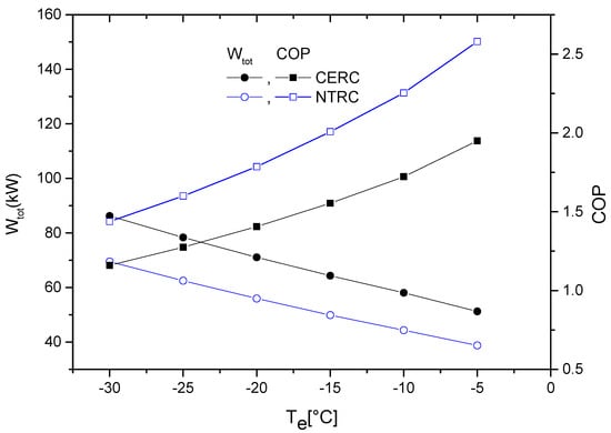
Figure 11.
The effect of Te on the cycles’ COP and Wnet.
The effect of Te on the 2nd law exergy efficiency and the overall exergy destruction is presented in Figure 12. As Te increases, a reduction in compressor power consumption is noticed, which reduces the total exergy destruction. A higher total exergy destruction rate of the CERC is noticed in comparison with the NTRC. The 2nd law efficiency versus Te is illustrated in Figure 12. The 2nd law efficiency of the NTRC is higher than that of the CERC. The difference between the 2nd law efficiency of the two cycles increases as the temperature of the evaporator increases.
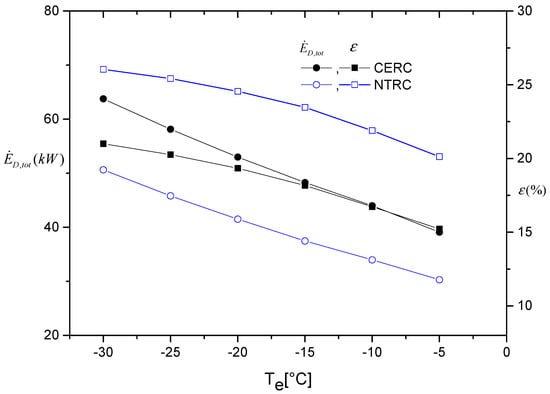
Figure 12.
The dependence of the exergy efficiency and overall amount of on evaporator temperature.
The effect of Te on the capital and the exergy destruction cost rates , the product’s final cost rate , and the exergoeconomic factor is shown in Figure 13. The increase in Te increases the exergoeconomic factor f and decreases the summation . At higher Te, the compressor pressure ratio is reduced, which results in a reduction of power requirement for compressor operation.
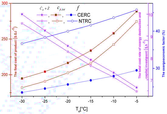
Figure 13.
The effect of Te on the exergoeconomic factor, the final cost of the product , and overall .
5. Conclusions
A novel transcritical refrigeration cycle is presented to improve the operational characteristics of a conventional ejector refrigeration cycle. Comprehensive exergy, energy, and exergoeconomic comparison of these two cycles are conducted. It was noted that the 2nd law efficiency shows an increase of 27.7%, and the destruction of the exergy rate is 22.25% less for the NTRC than that of the CERC. In addition, the COP of the NTRC is higher than that of CERC by 29%, and the 2nd law efficiency of the NTRC is higher than that of the CERC. A decrease of 6% in the final product’s cost of the NTRC is found in comparison to that of the CERC. The overall cost rates of exergy destruction and capital investment () is 7.735 and 7.91 $.h−1 for the NTRC and the CERC, respectively. It is found that the capital cost of investment is the predominant factor in comparison to the exergy destruction cost, which results in cheaper components that can be used in the NTRC. The final product cost of the proposed NTRC was found to be 6% less than that of the CERC, whereas the optimum value of the gas cooler pressure was 10.8 MPa, and 11.4 MPa for the NTRC and CERC, respectively. As mentioned in Table 6, NTRC has lower exergy destruction of the components in comparison to already published data. Finally, it is noted that the optimum Pgc of the NTRC is lowered by 0.6 MPa, which results in a longer lifetime and better safety of the system. As Pgc increases above 11 MPa, a constant value of the overall exergoeconomic factor f is maintained, and it is much lower for the CERC in comparison to that of the NTRC.
The proposed design of the NTRC has better performance in terms of COP and 2nd law efficiency in comparison to the traditional CERC. Therefore, the application of the NTRC is highly recommended to enhance the cycle performance and lower the optimum pressure. The outcome of the present work provides an excellent platform and basis for future works on the experimental work and design of a carbon dioxide transcritical refrigeration cycle with ejector.
Author Contributions
Formal analysis, B.T. and M.E.; Investigation, K.M.; Methodology, K.M.; Project administration, B.T. and M.E.; Resources, E.N.; Software, K.M.; Supervision, E.N., and L.K. All authors have read and agreed to the published version of the manuscript.
Funding
This research received no external funding.
Conflicts of Interest
The authors declare no conflict of interest.
Nomenclature
| Symbols | |
| c | Specific cost of exergy ($GJ−1) |
| Rate of cost | |
| CRF | The capital recovery factor |
| The exergy rate (kW) | |
| The total destruction rate of cost in exergy (kW) | |
| Factor of exergoeconomic | |
| h | The specific enthalpy, (kJ.kg−1) |
| i | The rate of interest |
| LMTD | The log mean temperature difference (K) |
| The rate of mass flow, (kg.s−1) | |
| N | Hours in the year (hr) |
| P | pressure (MPa) |
| The rate of heat transfer (kW) | |
| r | The difference in relative cost |
| s | The specific entropy (kJ.kg−1.k−1) |
| T | temperature (K) |
| The electrical power (kW) | |
| Z | The components of investment, cost ($) |
| The components of investment cost rate ($/h) | |
| Total capital cost rate ($/h) | |
| The efficiency (%) | |
| Abbreviations | |
| comp | Compressor |
| cond | Condenser |
| evap | Evaporator |
| EV | Expansion valve |
| GC | Gas cooler |
| Ejet | Ejector |
| tot | Total value |
| Subscripts | |
| 0 | State of environment |
| 1,2,3, | Cycle locations |
| F | The fuel |
| in | The inlet |
| is | The isentropic |
| k | Component |
| out | The outlet |
| p | The product |
References
- Sadorsky, P. Trade and energy consumption in the Middle East. Energy Econ. 2011, 33, 739–749. [Google Scholar] [CrossRef]
- Muhammad, B. Energy consumption, CO2 emissions and economic growth in developed, emerging and Middle East and North Africa countries. Energy 2019, 179, 232–245. [Google Scholar] [CrossRef]
- Salahuddin, M.; Gow, J. Economic growth, energy consumption, and CO2 emissions in Gulf Cooperation Council countries. Energy 2014, 73, 44–58. [Google Scholar] [CrossRef]
- Megdouli, K.; Tashtoush, B.M.; Nahdi, E.; Elakhdar, M.; Kairouani, L.; Mhimid, A. Thermodynamic analysis of a novel ejector cascade refrigeration cycles for freezing process applications and air-conditioning. Int. J. Refrig. 2016, 70, 108–118. [Google Scholar] [CrossRef]
- Luo, J.; Morosuk, T.; Tsatsaronis, G.; Tashtoush, B. Exergetic and Economic Evaluation of a Transcritical Heat-Driven Compression Refrigeration System with CO2 as the Working Fluid under Hot Climatic Conditions. Entropy 2019, 21, 1164. [Google Scholar] [CrossRef]
- Kauf, F. Determination of the optimum high pressure for transcritical CO2 refrigeration cycles. Int. J. Therm. Sci. 1999, 38, 325–330. [Google Scholar] [CrossRef]
- Liao, S.M.; Zhao, T.S.; Jakobsen, A. A correlation of optimal heat rejection pressures in transcritical carbon dioxide cycles. Appl. Therm. Eng. 2000, 20, 831–841. [Google Scholar] [CrossRef]
- Chen, J.; Havtun, H.; Palm, B. Conventional and advanced exergy analysis of an ejector refrigeration system. Appl. Energy 2015, 144, 139–151. [Google Scholar] [CrossRef]
- Aprea, C.; Maiorino, A. An experimental evaluation of the transcritical CO2 refrigerator performances using an internal heat exchanger. Int. J. Refrig. 2008, 31, 1006–1011. [Google Scholar] [CrossRef]
- Cabello, R.; Sánchez, D.; Llopis, R.; Torrella, E. Experimental evaluation of the energy efficiency of a CO2 refrigerating plant working in transcritical conditions. Appl. Therm. Eng. 2008, 28, 1596–1604. [Google Scholar] [CrossRef]
- Torrella, E.; Sánchez, D.; Llopis, R.; Cabello, R. Energetic evaluation of an internal heat exchanger in a CO2 transcritical refrigeration plant using experimental data. Int. J. Refrig. 2011, 34, 40–49. [Google Scholar] [CrossRef]
- Yu, B.; Yang, J.; Wang, D.; Shi, J.; Chen, J. An updated review of recent advances on modified technologies in transcritical CO2 refrigeration cycle. Energy 2019, 189, 116147. [Google Scholar] [CrossRef]
- Zhang, Q.; Luo, Z.; Zhao, Y.; Cao, R. Performance assessment and multi-objective optimization of a novel transcritical CO2 trigeneration system for a low-grade heat resource. Energy Convers. Manag. 2020, 204, 112281. [Google Scholar] [CrossRef]
- Llopis, R.; Nebot-Andrés, L.; Cabello, R.; Sánchez, D.; Catalán-Gil, J. Experimental evaluation of a CO2 transcritical refrigeration plant with dedicated mechanical subcooling. Int. J. Ref. 2016, 69, 361–368. [Google Scholar] [CrossRef]
- Dai, B.; Liu, S.; Zhu, K.; Sun, Z.; Ma, Y. Thermodynamic performance evaluation of transcritical carbon dioxide refrigeration cycle integrated with thermoelectric subcooler and expander. Energy 2017, 122, 787–800. [Google Scholar] [CrossRef]
- Nemati, A.; Mohseni, R.; Yari, M. A comprehensive comparison between CO2 and Ethane as a refrigerant in a two-stage ejector-expansion transcritical refrigeration cycle integrated with an organic Rankine cycle (ORC). J. Supercrit. Fluids 2018, 133, 494–502. [Google Scholar] [CrossRef]
- Enríquez, L.C.; Muñoz-Antón, J.; Peñalosa, J. S-Ethane Brayton power conversion systems for concentrated solar power plant. J. Sol. Energy Eng. 2016, 138, 011012. [Google Scholar] [CrossRef]
- Elakhdar, M.; Tashtoush, B.M.; Nehdi, E.; Kairouani, L. Thermodynamic analysis of a novel ejector enhanced vapor compression refrigeration (EEVCR) cycle. Energy 2018, 163, 1217–1230. [Google Scholar] [CrossRef]
- Tashtoush, B.; Algharbawi, A. Parametric Study of a Novel Hybrid Solar Variable Geometry Ejector Cooling with Organic Rankine Cycles. Energy Convers. Manag. 2019, 198, 111910. [Google Scholar] [CrossRef]
- Zare, V.; Takleh, H. Novel geothermal driven CCHP systems integrating ejector transcritical CO2 and Rankine cycles: Thermodynamic modeling and parametric study. Energy Convers. Manag. 2020, 205, 112396. [Google Scholar] [CrossRef]
- Taslimitaleghani, S.; Sorin, M.; Poncet, S. Energy and exergy efficiencies of different configurations of the ejector-based CO2 refrigeration systems. Int. J. Energy Prod. Manag. 2018, 3, 22–33. [Google Scholar] [CrossRef]
- Tashtoush, B.; Bani Younes, M. Comparative Thermodynamic Study of Refrigerants to Select the Best Environment-Friendly Refrigerant for Use in a Solar Ejector Cooling System. Arab. J. Sci. Eng. 2019, 44, 1165–1184. [Google Scholar] [CrossRef]
- Gholizadeh, T.; Vajdi, M.; Rostamzadeh, H. Freshwater and cooling production via integration of an ethane ejector expander transcritical refrigeration cycle and a humidification dehumidification unit. Desalination 2020, 477, 114259. [Google Scholar] [CrossRef]
- Farsi, A.; Mohammadi, S.; Ameri, M. An efficient combination of transcritical CO2 refrigeration and multi-effect desalination: Energy and economic analysis. Energy Convers. Manag. 2016, 127, 561–575. [Google Scholar] [CrossRef]
- Elakhdar, M.; Landoulsi, H.; Tashtoush, B.; Nehdi, E.; Kairouani, L. A combined thermal system of ejector refrigeration and Organic Rankine cycles for power generation using a solar parabolic trough. Energy Convers. Manag. 2019, 199, 111947. [Google Scholar] [CrossRef]
- Megdouli, K.; Sahli, H.; Tashtoush, B.M.; Nahdi, E.; Kairouani, L. Theoretical research of the performance of a novel enhanced transcritical CO2 refrigeration cycle for power and cold generation. Energy Convers. Manag. 2019, 201, 112139. [Google Scholar] [CrossRef]
- Sarkar, J.; Agrawal, N. Performance optimization of transcritical CO2 cycle with parallel compression economization. Int. J. Therm. Sci. 2010, 49, 838–843. [Google Scholar] [CrossRef]
- Manjili, F.; Cheraghi, M. Performance of a new two-stage transcritical CO2 refrigeration cycle with two ejectors. Appl. Therm. Eng. 2019, 156, 402–409. [Google Scholar] [CrossRef]
- Gullo, P.; Elmegaard, B.; Cortella, G. Energetic, exergetic and exergoeconomic analysis of CO2 refrigeration systems operating in hot climates. In Proceedings of the ECOS: 28th International Conference on Efficiency, Cost, Optimization, Simulation and Environmental Impact of Energy Systems, Pau, France, 30 June–3 July 2015. [Google Scholar]
- Chesi, A.; Esposito, F.; Ferrara, G.; Ferrari, L. Experimental analysis of R744 parallel compression cycle. Appl. Energy 2014, 135, 274–285. [Google Scholar] [CrossRef]
- Megdouli, K.; Tashtoush, B.M.; Ezzaalouni, Y.; Nahdi, E.; Mhimid, A.; Kairouani, L. Performance analysis of a new ejector expansion refrigeration cycle (NEERC) for power and cold: Exergy and energy points of view. Appl. Therm. Eng. 2017, 122, 39–48. [Google Scholar] [CrossRef]
- Ipakchi, O.; Mosaffa, A.; Farshi, L. Ejector based CO2 transcritical combined cooling and power system utilizing waste heat recovery: A thermoeconomic assessment. Energy Convers. Manag. 2019, 186, 462–472. [Google Scholar] [CrossRef]
- Fazelpour, F.; Morosuk, T. Exergoeconomic analysis of carbon dioxide transcritical refrigeration machines. Int. J. Refrig. 2014, 38, 128–139. [Google Scholar] [CrossRef]
- Wu, D.; Han, Z.; Liu, Z.; Zhang, H. Study on configuration optimization and economic feasibility analysis for combined cooling, heating and power system. Energy Convers. Manag. 2019, 190, 91–104. [Google Scholar] [CrossRef]
- Tashtoush, B.; Nayfeh, Y. Energy and economic analysis of a variable-geometry ejector in solar cooling systems for residential buildings. J. Energy Storage 2020, 27, 101061. [Google Scholar] [CrossRef]
- Meng, F.; Wang, E.; Zhang, B.; Zhang, F.; Zhao, C. Thermo-economic analysis of transcritical CO2 power cycle and comparison with Kalina cycle and ORC for a low temperature heat source. Energy Convers. Manag. 2019, 195, 1295–1308. [Google Scholar] [CrossRef]
- Liu, Z.; Cao, F.; Guo, J.; Liu, J.; Zhai, H.; Duan, Z. Performance analysis of a novel combined cooling, heating and power system based on carbon dioxide energy storage. Energy Convers. Manag. 2019, 188, 151–161. [Google Scholar] [CrossRef]
- Tashtoush, B.M.; Al-Nimr, M.A.; Khasawneh, M.A. Investigation of the use of nano-refrigerants to enhance the performance of an ejector refrigeration system. Appl. Energy 2017, 206, 1446–1463. [Google Scholar] [CrossRef]
- Takleh, H.; Zare, V. Performance improvement of ejector expansion refrigeration cycles employing a booster compressor using different refrigerants: Thermodynamic analysis and optimization. Int. J. Refrig. 2019, 101, 56–70. [Google Scholar]
- Nakagawa, M.; Marasigan, A.R.; Matsukawa, T.; Kurashina, A. Experimental investigation on the effect of mixing length on the performance of two-phase ejector for CO2 refrigeration cycle with and without heat exchanger. Int. J. Refrig. 2011, 34, 1604–1613. [Google Scholar] [CrossRef]
- Kairouani, L.; Elakhdar, M.; Nehdi, E.; Bouaziz, N. Use of ejectors in a multi evaporator refrigeration system for performance enhancement. Int. J. Refrig. 2009, 32, 1173–1185. [Google Scholar] [CrossRef]
- Zheng, L.; Deng, J. Experimental investigation on a transcritical CO2 ejector expansion refrigeration system with two-stage evaporation. Appl. Therm. Eng. 2017, 125, 919–927. [Google Scholar] [CrossRef]
- Liu, F.; Groll, E.A.; Ren, J. Comprehensive experimental performance analyses of an ejector expansion transcritical CO2 system. Appl. Therm. Eng. 2016, 98, 1061–1069. [Google Scholar] [CrossRef]
- Bai, T.; Yan, G.; Yu, J. Thermodynamics analysis of a modified dual-evaporator CO2 transcritical refrigeration cycle with two-stage ejector. Energy 2015, 84, 325–335. [Google Scholar] [CrossRef]
- Sharma, V.; Fricke, B.; Bansal, P. Comparative analysis of various CO2 configurations in supermarket refrigeration systems. Int. J. Refrig. 2014, 46, 86–99. [Google Scholar] [CrossRef]
- Deng, J.Q.; Jiang, P.X.; Lu, T.; Lu, W. Particular characteristics of transcritical CO2 refrigeration cycle with an ejector. Appl. Therm. Eng. 2007, 27, 381–388. [Google Scholar] [CrossRef]
- Bilir, N.; Ersoy, H. Performance improvement of the vapour compression refrigeration cycle by a two-phase constant area ejector. Int. J. Energy Res. 2009, 33, 469–480. [Google Scholar] [CrossRef]
- Elbel, S.; Lawrence, N. Review of recent developments in advanced ejector technology. Int. J. Refrig. 2016, 62, 1–18. [Google Scholar] [CrossRef]
- Zhu, Y.; Li, C.; Zhang, F.; Jiang, P.X. Comprehensive experimental study on a transcritical CO2 ejector-expansion refrigeration system. Energy Convers. Manag. 2017, 151, 98–106. [Google Scholar] [CrossRef]
- Mosaffa, A.; Farshi, G. Thermodynamic and economic assessments of a novel CCHP cycle utilizing low-temperature heat sources for domestic applications. Renew. Energy 2018, 120, 134–150. [Google Scholar] [CrossRef]
- Xia, J.; Wang, J.; Zhou, K.; Zhao, P.; Dai, Y. Thermodynamic and economic analysis and multi-objective optimization of a novel transcritical CO2 Rankine cycle with an ejector driven by low grade heat source. Energy 2018, 161, 337–351. [Google Scholar] [CrossRef]
- Yu, J.; Ren, Y.; Chen, H.; Li, Y. Applying mechanical subcooling to ejector refrigeration cycle for improving the coefficient of performance. Energy Convers. Manag. 2007, 48, 1193–1199. [Google Scholar] [CrossRef]
- Dincer, I.; Rosen, M.; Ahmadi, P. Optimization of Energy Systems; Wiley: London, UK, 2017. [Google Scholar]
- Bejan, A.; Tsatsaronis, G.; Moran, M. Thermal Design and Optimization; John Wiley & Sons, Inc.: New York, NY, USA, 1996. [Google Scholar]
- Yao, E.; Wang, H.; Wang, L.; Xi, G.; Maréchal, F. Multi-objective optimization and exergoeconomic analysis of a combined cooling, heating and power based compressed air energy storage system. Energy Convers. Manag. 2017, 138, 199–209. [Google Scholar] [CrossRef]
- Li, Y.; Deng, J.; Ma, L. Experimental study on the primary flow expansion characteristics in transcritical CO2 two-phase ejectors with different primary nozzle diverging angles. Energy 2019, 186, 115839. [Google Scholar] [CrossRef]
- Ersoy, H.; Bilir, N. The influence of ejector component efficiencies on performance of Ejector Expander Refrigeration Cycle and exergy analysis. Int. J. Exergy 2010, 7, 425–438. [Google Scholar] [CrossRef]
© 2020 by the authors. Licensee MDPI, Basel, Switzerland. This article is an open access article distributed under the terms and conditions of the Creative Commons Attribution (CC BY) license (http://creativecommons.org/licenses/by/4.0/).