Abstract
In order to achieve better dynamics performances of a class of automobile active suspensions with the model uncertainties and input delays, this paper proposes a generalized robust linear H2/H∞ state feedback control approach. First, the mathematical model of a half-automobile active suspension is established. In this model, the H∞ norm of body acceleration is determined as the performance index of the designed controller, and the hard constraints of suspension dynamic deflection, tire dynamic load and actuator saturation are selected as the generalized H2 performance output index of the designed controller to satisfy the suspension safety requirements. Second, a generalized H2/H∞ guaranteed cost state-feedback controller is developed in terms of Lyapunov stability theory. In addition, the Cone Complementarity Linearization (CCL) algorithm is employed to convert the generalized H2/H∞ output-feedback control problem into a finite convex optimization problem (COP) in a linear matrix inequality framework. Finally, a numerical simulation case of this half-automobile active suspension is presented to illustrate the effectiveness of the proposed controller in frequency-domain and time-domain.
1. Introduction
With the application and implement of automobile suspension design, it is necessary to attain a well balance between the handling stability and ride quality, which are usually contradictive with each other [1,2,3]. To mention that, how to cooperate with these two conflicting performance indicators has been a research hotspot currently [4,5,6]. Over the past decades, to address the issue of active suspension control, many researchers have proposed a lot of control methods such as linear optimal control [7], fuzzy neutral network control [8], adaptive robust control [9], robust control and nonlinear control [10], etc.
In a real engineering application, a class of active suspension system (ASS) should keep the desirable dynamics performance in case of sustaining the model uncertainty caused by the body mass, and the actuator input delay that is unavoidable in the control system, see [11] in detail. On one side, if the model parameter uncertainties are not taken into account in the process of controller design, then it will deteriorate suspension performances to some extent, which not only affects the ride comfort, but also endangers the driving safety. Therefore, it is very necessary to take the parametric uncertainties of the control plant into account, and then to develop a robust control method with higher accuracy. On the other side, as demonstrated in [12], for the controller design of a vehicle active suspension, there inevitably exists input delay that may generated from the controller calculations, the signal acquiring of sensor, along with the actuator operation. Once occurring the input delay in a closed-loop system, it means that the working stats of the control system at one time will not only be determined by the current system states, but also be affected by the system condition at the previous time. Although the input delay is very important in the control scheme design and development, it is usually ignored by a lot of researchers, like [7,8,9,10,11,12]. However, it is needed to know that even a small input delay may result in the decrease of control efficiency and the instability of control system [13,14].
In recent years, the robust H∞ and H2 control theory and technique have received extensive attentions. This is because the H∞ control approach can easily handle the hard constraint problem of ASS in time domain, and the safety constraints condition can be restrained within a finite range, thus the vehicle body vibrations can be maximally inhibited in the presence of uneven road surface; moreover, H2 control can effectively handle the convergence rate of the closed-loop control system. For instances, literature [15,16] designed a mixed H2/H∞ controller by using linear matrix inequality (LMI) method, and conducted a comparative study for the ASS with H∞ controller by itself. Note that the effects of the parameter perturbations in vehicle active suspensions on the designed controller are not considered. Literature [17,18] also designed a class of mixed H2/H∞ controllers for ASS, but the model uncertainty issue is not considered. In literature [19], the authors have developed a full-state feedback controller with considering the input delay for a seat suspension system, and this controller achieved better control effects in a certain delay range. These studies inspired our study along this direction.
Synthesizing the above discussions, this paper presents a robust generalized H2/H∞ full state feedback controller for the ASS. Compared with the related studies in [12,13,14,15,16,17,18,19,20,21], the key contribution points lie in the two aspects:
(1) a comprehensive dynamics model of ASS is established with incorporating the input delay and parametric uncertainties, and the H∞ norm of the body vertical acceleration is taken as the controller output performance index, meanwhile, the hard constraints of suspension dynamic deflections, tire dynamic loads and the actuator saturations are taken as the generalized H2 performance index for the desirable controller.
(2) a generalized robust H2/H∞ state feedback control law is designed and this controller design issue is converted into a COP in the LMI framework, which simplifies the controller solution.
Finally, a numerical example of half-vehicle suspension is presented to validate the effectiveness of our proposed mixed H2/H∞ full state feedback controller.
We organize the rest of this work as follows. Section 2 gives the system model and problem formulation. The proposed controller is discussed in Section 3 in detail. Section 4 summarizes the simulation investigations to reveal the designed controller’s effectiveness. In Section 5, we will display the conclusions.
2. System Model and Problem Formulation
2.1. Automobile Active Suspension with Input Time Delay
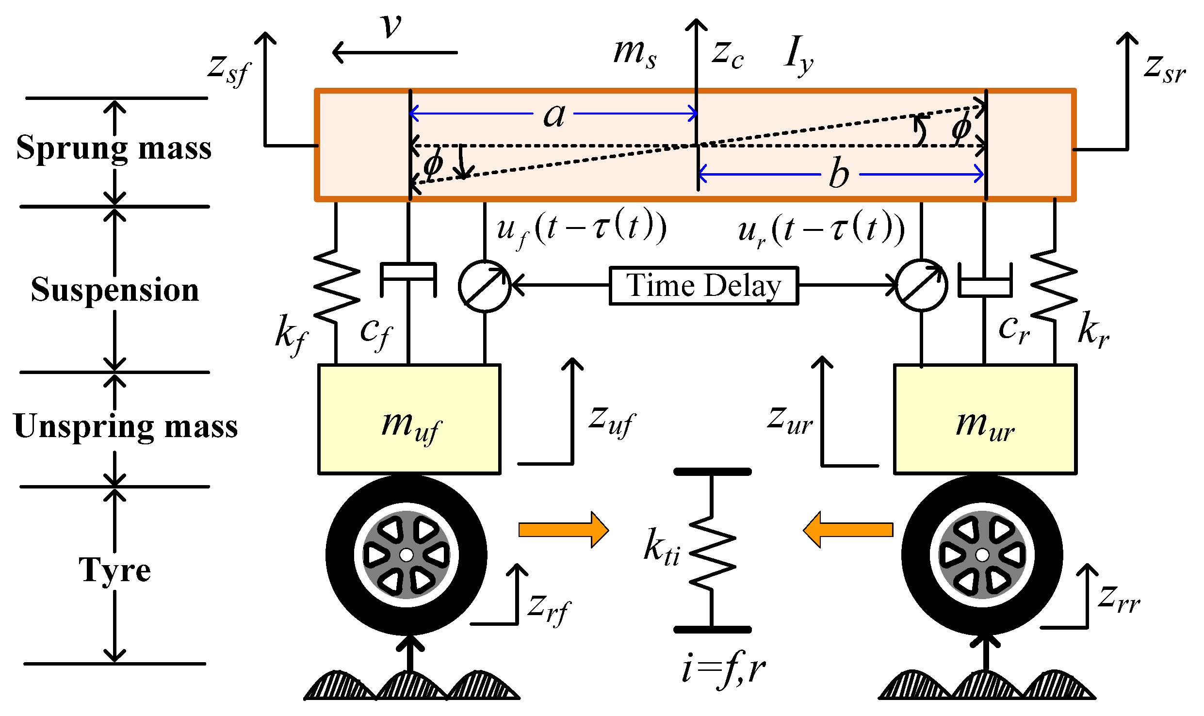
Figure 1 shows a half-automobile dynamics model that is extensively employed in literatures such as [14,20]. According to the second law of Newton, the dynamics equations can be constructed as
where , and ; is the input vector of road surface, is the input vector of actuator control force for this ASS. In Equations (1) and (2), the coefficient matrices of , , , , and are respectively given as
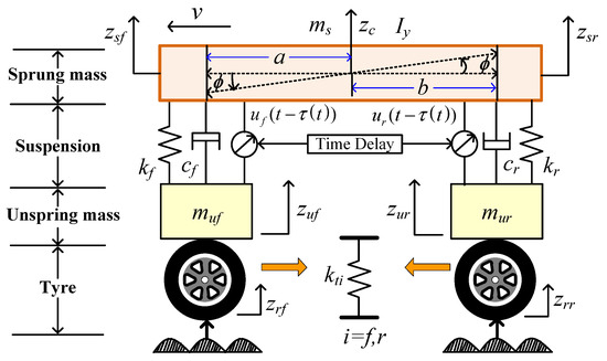
Figure 1.
Dynamics model of half-automobile active suspension system (ASS).
To ensure that ASS has a better dynamics characteristic and meets this automobile suspension safety performance’s requirements, the control objectives can be summarized as [22]:
(1) Ride comfort
To obtain better the performances of vehicle dynamics, the designed controller should guarantee the minimization of and .
(2) Running safety
① The dynamic displacements should be less than its allowable maximum value of , which are expressed by
② The tire’s dynamic load must be restrained within the corresponding static load, i.e., , wherein is the dynamic loads at the front and rear tire, is expressed by
③ The control forces should not exceed its maximum value of , which is given by
To achieve the above control goals, define as the dynamics output vector, and as the normalized constraint output vector, for this automobile ASS, which are expressed by
where .
Considering input time delay τ, the system can be obtained.
where is the state vector, is the control force vector, is the input disturbance vector, is the continuous differentiable initial condition function. , , , , , and are the corresponding coefficient matrices with appropriate dimension, which are given as follows:
where in A, B1, B2, C, D and E are the coefficient matrices with appropriate dimension, respectively, and they are dependent with the model parametric uncertainties, which will be illustrated in the subsequent section, and all the detailed matrices are given in Appendix A.
2.2. Active Suspension Model with Time Delay and Parameter Uncertainties
Based on Equation (6), the following closed-loop systems against parameter uncertainties and time delay can be obtained as
where , represent the quantized uncertainty of ms, and it can be expressed in a norm-bounded form as
where in , and are the corresponding coefficient matrices with appropriate dimension, and is the unknown time-varying matrix function, which are mathematically constrained by
According to the performance requirements of ASS, the designed state-feedback control law is designed as
where is the determined controller gain matrix.
Substituting Equation (10) into Equation (7) yields
Herein, by referring to [4,5,6], we summarize the robust state feedback controller (RSFC) design in Equation (11) as follows:
- (a)
- The system in Equation (11) is asymptotically stable.
- (b)
- Given , the H∞ norm of the transfer function from to should be satisfied with Equation (12) under the zero initial conditions.where is a minimized positive value and .
- (c)
- Given and the positive constant , under zero initial conditions, the generalized H2 norm of the transfer function from to should be satisfied as follows:where , , indicates the deterministic constraint index in the vector .
3. Robust Controller Design with Input Delay and Parameter Uncertainties
Lemma 1.
[23]: Assume that , and are defined on the interval , then there exists an arbitrary matrix , and satisfying
where
Lemma 2.
[22]: Given matrices , , satisfies for all satisfying , if and only if there exists some such that
Theorem 1.
The system in Equation (11) for the automobile active suspension model has the asymptotical stability property satisfying Equations (12) and (13) for all non-zero , , , and . If and only if there exists positive definite matrices , , , , , and such that the inequalities are satisfied
where , , is expressed as
where
Proof.
For the closed-loop system in Equation (11), one can design the Lyapunov-Krasovskii as
where , , . It is noted that , and are the undetermined matrices.
In order to acquire the designed controller, two steps are provided to prove Theorem 1.
Step 1. Validate the asymptotical stability of the closed-loop system in Equation (11) with guaranteeing the H∞ performance index of system in Equation (11) and satisfying .
The time derivative of V1 in Equation (19) is
According to Leibniz–Newton formula, we have
Substituting Equation (20) into Equation (11) of parameter certainties leads to
Substituting Equation (22) to Equation (20), we have
Define , , , according to Lemma 1, we have
where
Substituting Equation (24) to Equation (23), we have
The derivative of V2 is
The derivative of V3 is
Substituting Equations (26), (27) and (28) into Equation (19), we obtain
Assume , , then . Consider the following index
Then, for non-zero , we have
where
when assuming , if , then and (11) is asymptotically stable. Moreover, for w(t) , we can get and , in zero initial conditions, it can guarantees that the system in Equation (11) has a given attenuation level .
By using Schur complement, the inequality is transformed into
where .
Define pre-and post-multiplying Equation (32) by and its transpose, we obtain
where .
After substituting , we further obtain
Considering the parameter uncertainties, replacing A by and B by in Equation (34), we can get
where
By using Lemma 2 in the above equation, there exist a scalar such that
By applying Schur complement, the inequalities of Equation (36) is equivalent to
Substitute into Equation (37), we obtain Equation (16).
Pre- and post-multiplying the inequality in Equation (25) by and its transpose, we can obtain
Substitute and into the above equation, we obtain Equation (17).
Step 2. Guarantee that generalized H2 performance index of Equation (11) satisfies with .
According to Equation (30) and , we have
Due to , we have
Integrating Equation (40) gives
Synthesizing the above discussions, we can derive that the last two terms of Equation (19) are positive definite, so we can further get
Multiplying the inequality in Equation (42) by , we have
So that, only if the inequality holds with and
Consequently, we further get
If Equation (45) holds, it is only needed to be ensured that Equation (46) comes into existence.
By Schur complement, we obtain
Multiplying the inequality in Equation (47) by and then using the congruent transformation in matrix, we get (18). The proof is completed. □
The nonlinear term LR−1L in Equation (17) lead to the inability to use the LMI algorithm to solve the controller gain K. We need to transform inequalities into cone complementary linearization iterative problem of LMI algorithm.
For the nonlinear term LR−1L in Equation (17), there is a new variable S such that
According to Equation (49), we have
By applying Schur complement, the condition of Equation (50) is equal to
By introducing new variables , we obtain
Now, in terms of a CCL problem description, it is suggested that the orignal non-convex feasibility problem of Theorem 1 can be trasnformed into the following non-linear minimization problem with LMI conditions:
The specific steps for solving the above problem in Equation (53) are described as follows:
Step-1, Given initial value and .
Step-2, Find out a feasible set () with satisfying Equations (16), (18) and (53). If there is no solution, then exit. If there exist solutions, verify whether the condition in Equation (17) holds. Find the feasible set that meets the above requirements, if condition (17) is established, the iteration is completed. If it is not established, it enters Step-3 and sets k = 1.
Step-3, Solve the following LMI problem for the variables ()
Subject to Equations (16), (18) and (53). Set and .
Step-4, Substitute the result obtained in Step-3 into Equation (17), we need to verify whether the inequality holds. If it is true, the iteration ends. If it is not true, and the number of iterations is within 100 times, perform Step-3 again and continue the iteration.
Step-5, Repeat Step-2~Step-4 by decreasing appropriately and iterate again.
4. Simulation Investigation and Discussion
In this section, a numerical example is uesd to verify the proposed robust controller’s effectiveness under bump and random road disturbances, respectively. Table 1 give the used parameters of the simulation.

Table 1.
The parameters of half-vehicle ASS.
It is assumed that zfmax = zrmax = 0.1 m, Fmax = 1500 N, ms has a perturbation of ± 10% and the matrix H, E1, E2 for the uncertain in Equation (4).
In the condition of the given time delay τ(t) = 20ms and the generalized H2 performance index of 26.4537, the H∞ performance index is elected as 28.2843. Based on Theorem 1, the input delay of the proposed robust controller can be calculated by the cone complement linearization algorithm. The control gain matrix K is obtained as
4.1. Simulation Results in Frequency Domain
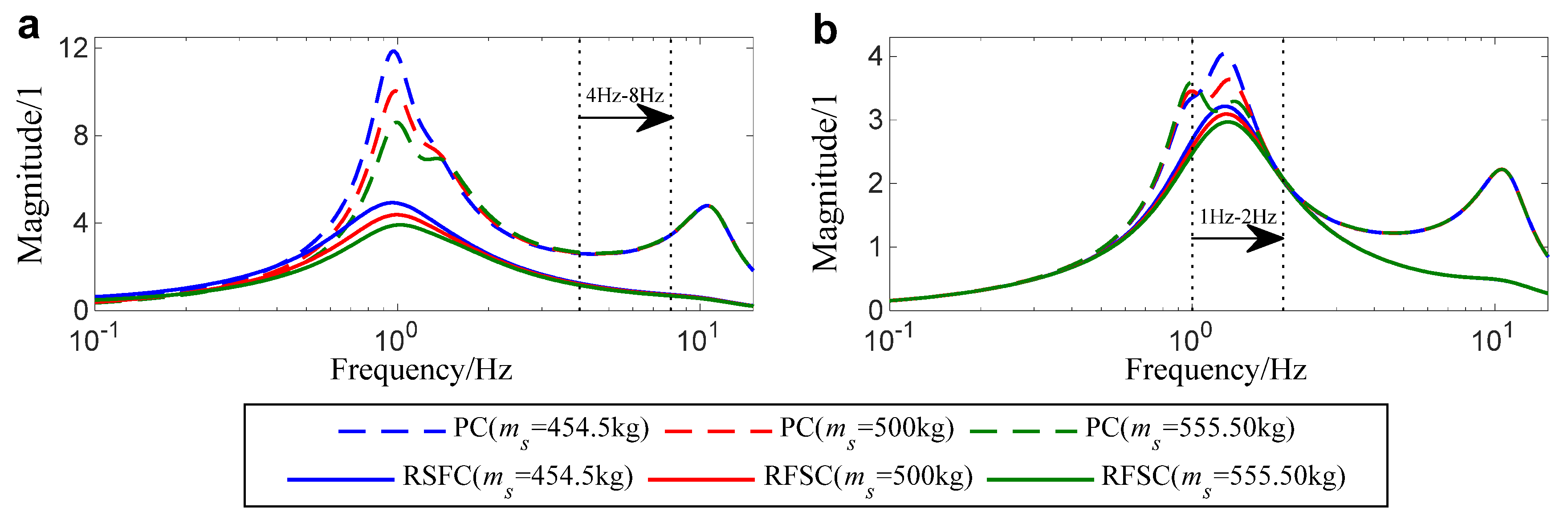
Based on ISO 2361 criteria, in vertical vibration, the human bodies are sensitive to about 4–8 Hz, in pitch vibration directions, the human bodies are sensitive to about 1–2 Hz.
Figure 2 shows the response comparisons of and in the frequency domain in case of ms = 454.5 kg, ms = 500 kg and ms = 555.5 kg, respectively. It is obvious that, compared to the passive control (PC), RSFC can attain a better control performance on the whole, especially in the frequency ranges of 4–8 Hz for the vertical direction, and 1–2 Hz for the pitch direction, respectively. In addition, even for the propsoed RSFC, we can see that the parameter uncertianty of body mass ms hardly impose any effects on the output performances, which means the desinged RSFC can be tolerant with the variatons of body mass uncertainty.
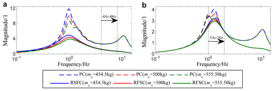
Figure 2.
Response comparisons of (a)
and (b) in the frequency domain.
4.2. Bump Road Response in Time Domain
The bump road is also utilized to conduct the simulations under bump road surface, which is described in literature [21] and is mathematically given by
where hb, and v represent the height of the bump, and the vehicle forward speed, respectively, and the time input delay is expressed by (a + b)/v, where their corresponding values is given as hb = 0.1 m and v = 45 (km/h).
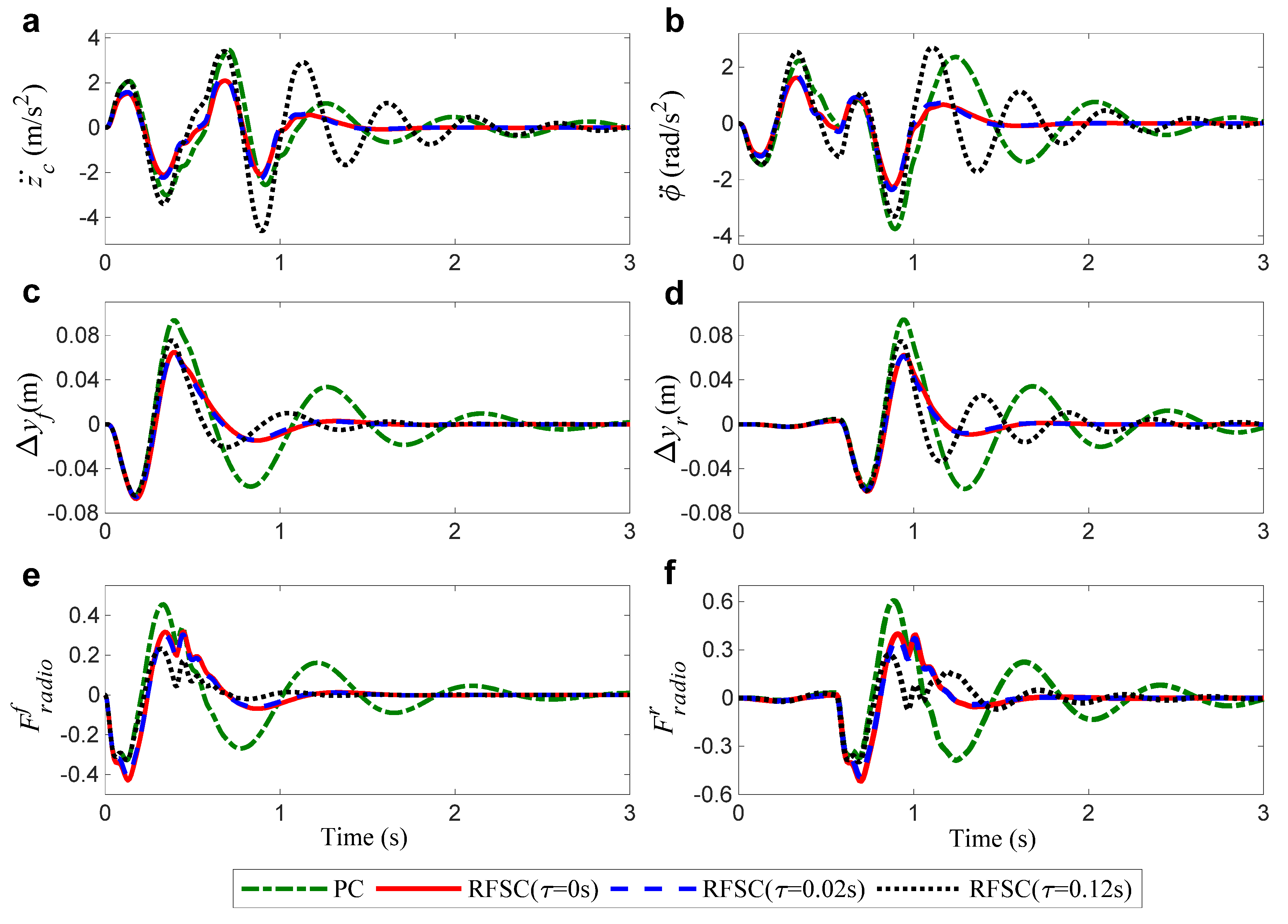
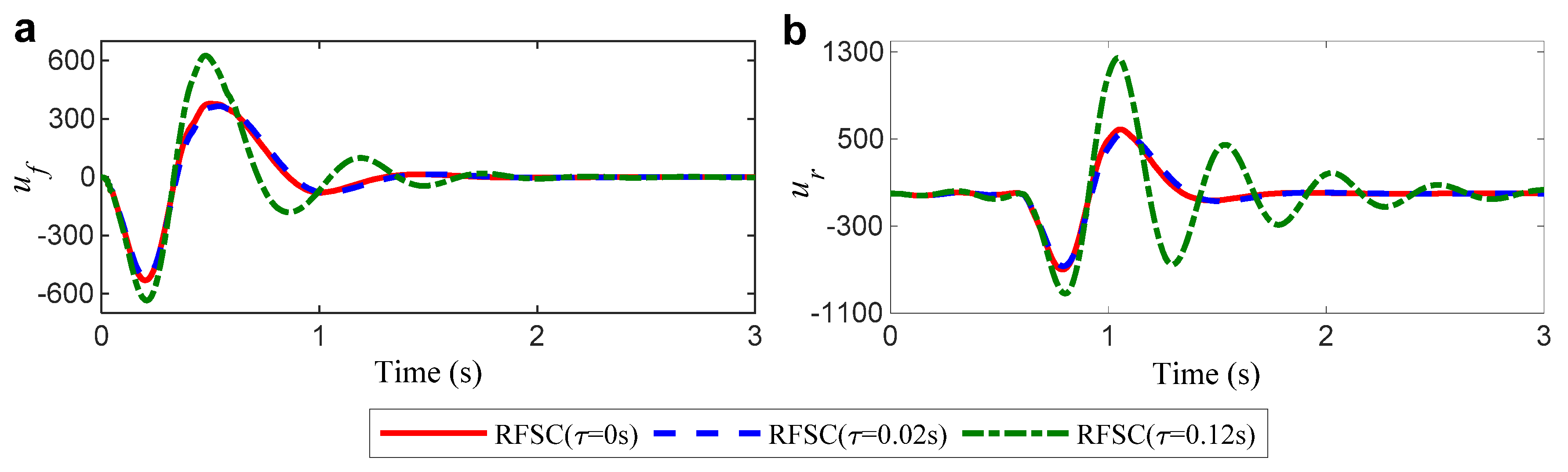
Figure 3 and Figure 4 show the bump responses results of , , , , , , and for the passsive controlled system (u(t) = 0) and ASS with the proposed RSFC when there exists time delay as , and , respectively. The simulation results from Figure 3a,b show that when the input delay are 0 and 0.02 s, compared with PC, and with RSFC can be remarkably reduced, and then reach into asymptotic stability within a shorter time. However, when the input delay is increased to 0.12 s, the amplitude of and is very high, and the dynamic stability cannot be achieved in the simulation time 3 s. The ASS’s index of and with RSFC have the smaller positive peaks, they are all less than the value of and in PC system; and are always less than 1, implying that the dynamic load is less than its static load and ensuring the firm uninterrupted contact from the wheels to the road. Additionally, it can be seen from Figure 4 that and are always less than umax, satisfying the actuator input saturation requirement.
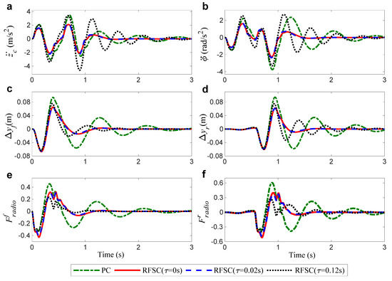
Figure 3.
Response comparisons of (a) and (b) , (c) , (d) , (e) , (f) under bump road disturbances.
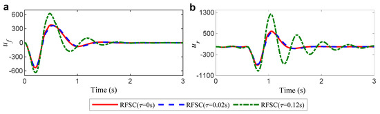
Figure 4.
Response comparisons of (a) and (b) under bump road disturbances.
4.3. Random Road Response in Time Domain
In order to further verify the control effectiveness of the designed RSFC, a random road surface mimicked by the Gaussian white noise is used to conduct the simulation, which is expressed by [24]
wherein n0 represent the reference spatial frequency, f0 represent the lower cut-off frequency for different road profiles, ω(t) represent zero mean the white Gaussian noise signal, Gq(n0) represent the road roughness coefficient. Herein, the parameter values of road surface are chosen as n0 = 0.1 (1/m), Gq(n0) = 64 × 10−6 (m3) and v = 45 (km/h), which corresponds to B-class road surface.
The root mean square (RMS) is employed to further analyze the robustness of the RSFC to different input delays and the influence of ASS’s control performance. The RMS expression of the variable x(t) is defined [23]:
For different input time delay in the closed-loop system, the controller’s effectiveness in dealing with the time delay problem is studied by calculating the following RMS ratios as
Among Equation (57), , , , , and mean the RMS values of the proposed RSFC system, and means the RMS value of the PC system.
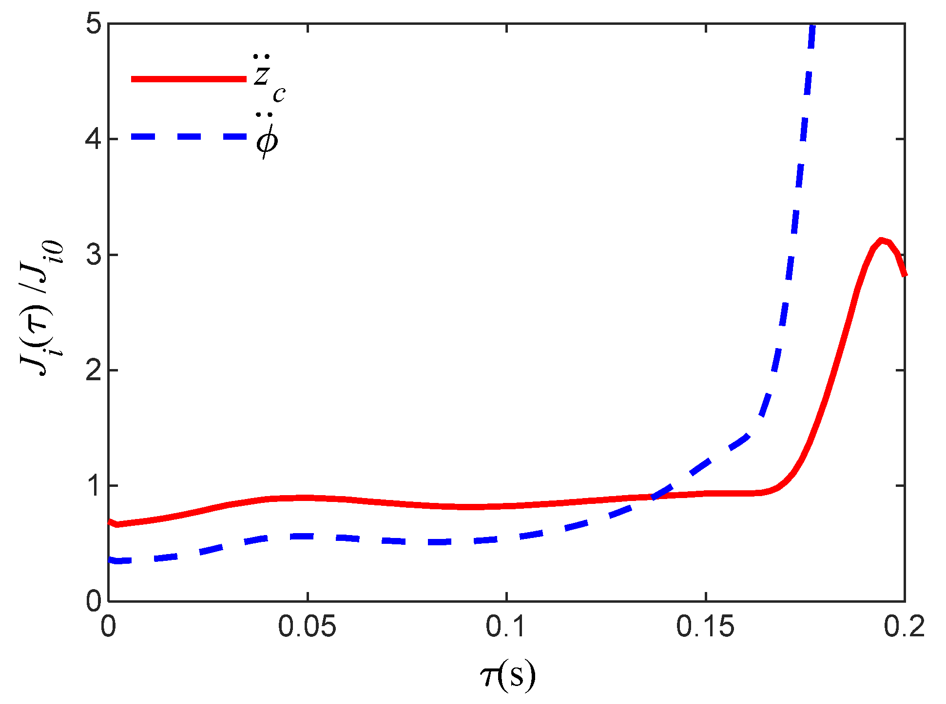
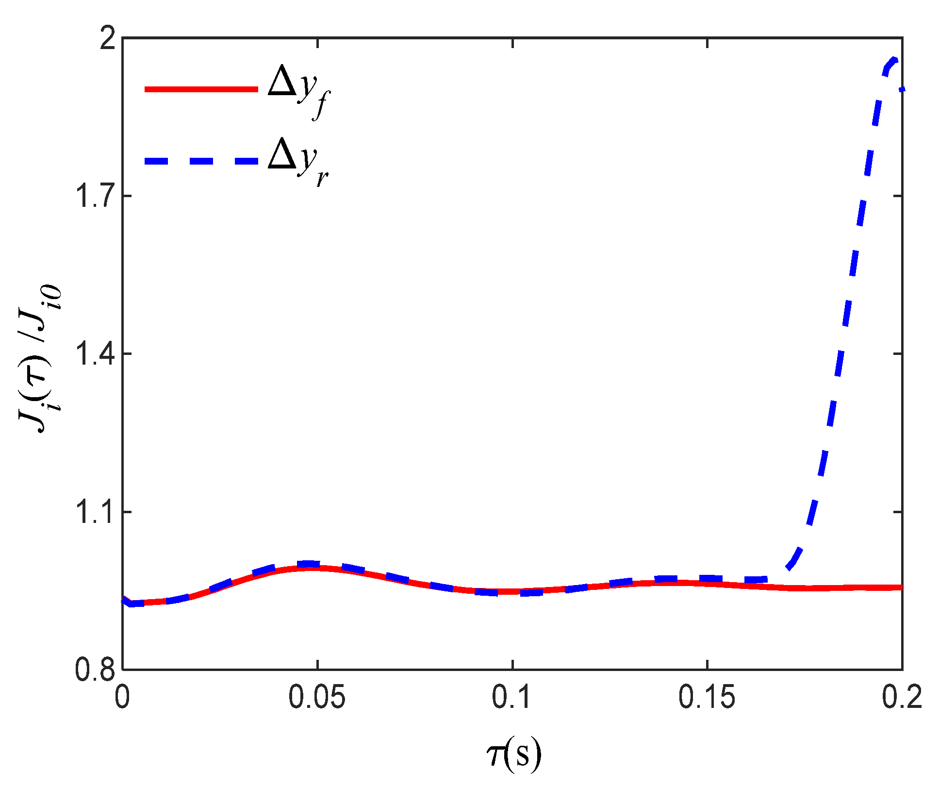
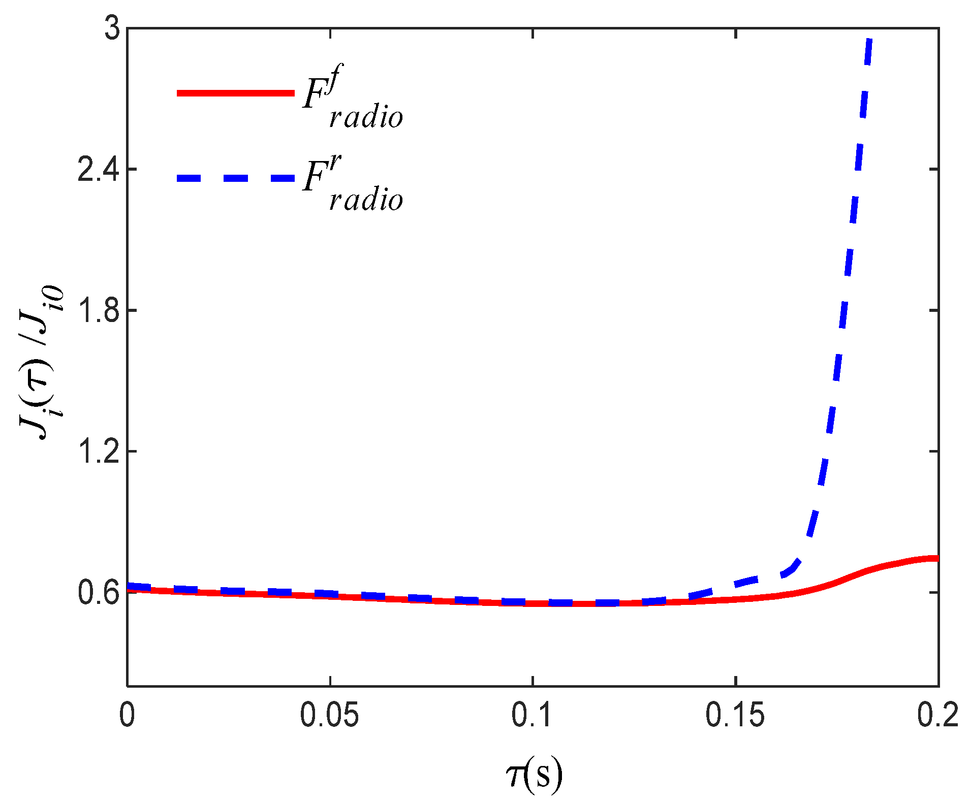
As shown in Figure 5, Figure 6 and Figure 7, the RMS ratios of , , , , and are all less than 1 when , which denotes that the designed controller’s performance is much better than the passive suspension. With the increase of time delay, the RMS ratio, especially , , and , increases dramatically, which reflects the sharp deterioration of ASS performance under the input time delay of about 0.12 s or more, and the controlled ASS tends to be unstable.
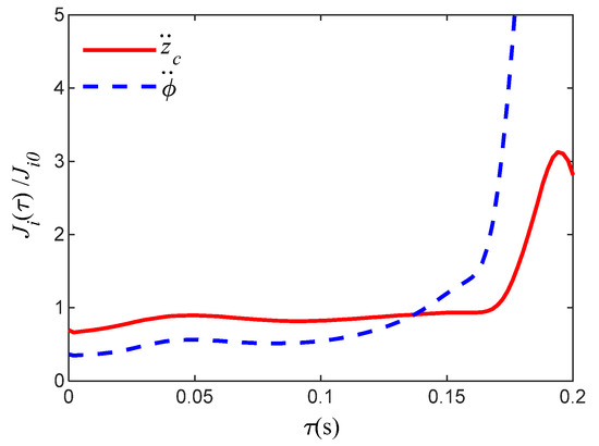
Figure 5.
The RMS ratio of and under different input time delay and B-class road surface.

Figure 6.
The RMS ratio of and under different input time delay and B-class road surface.
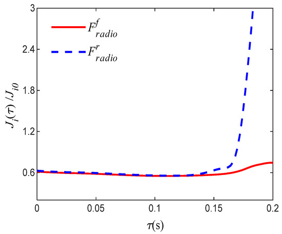
Figure 7.
The RMS ratio of and under different input time delay and B-class road surface.
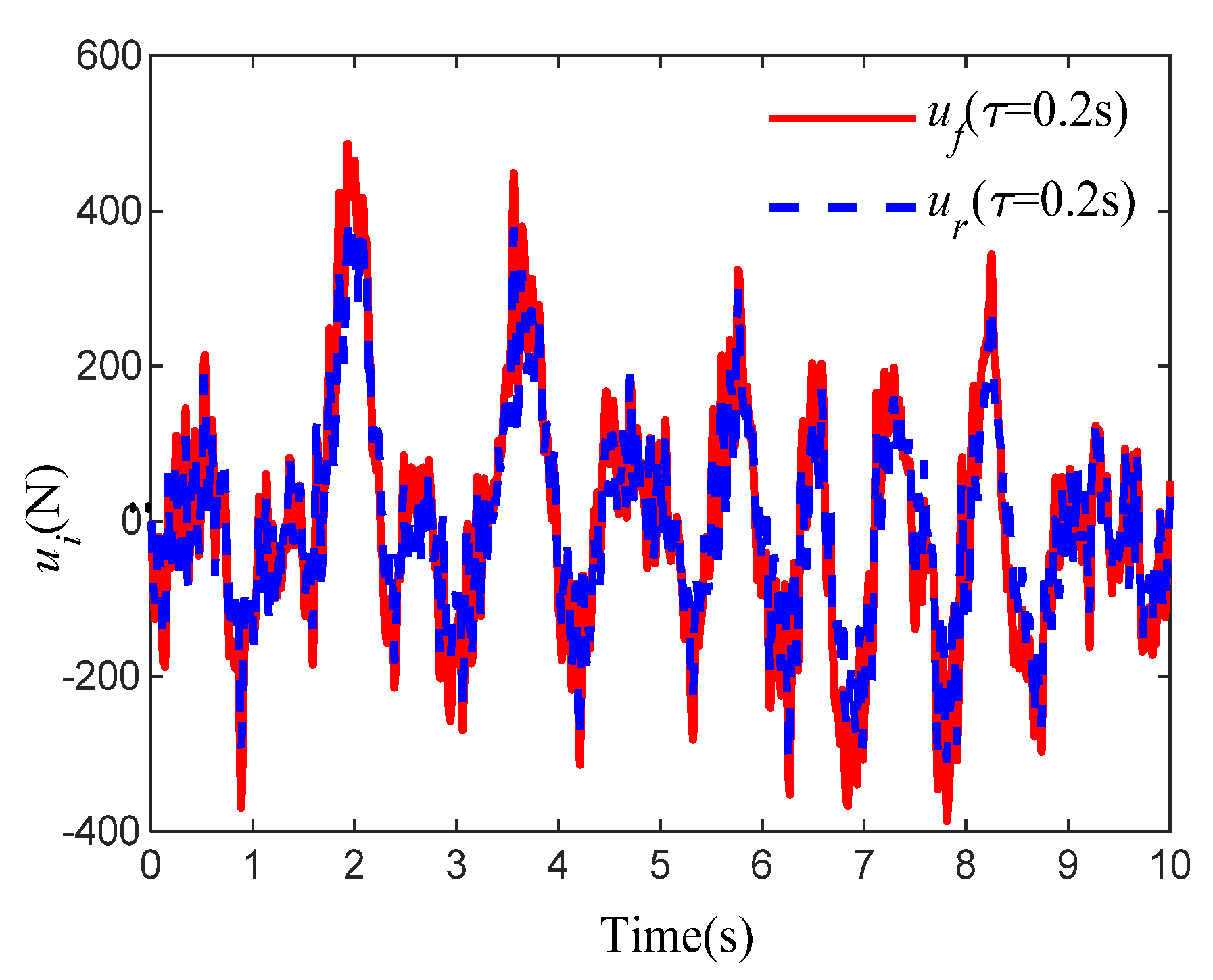
The results reveal that the proposed design method is conservative. Additionally, it can be seen from Figure 8 that and are always less than umax with satisfying the actuator input saturation requirement.

Figure 8.
Response comparisons of and under B-class random road.
5. Conclusions
- (1)
- A half-vehicle active suspension model considering the parameter uncertainties, input delay, as well as the external road surface disturbances is established. the H∞ norm of vehicle body acceleration is selected as the performance index of the controller output. The hard constraints of suspension dynamic deflections, tire dynamic loads and actuator saturations are taken as the generalized H2 performance output index of the designed controller. A robust controller based on cone complementary linearization algorithm is proposed.
- (2)
- The simulation experiments under different road excitations show that the generalized H2/H∞ controller in this paper can tolerate the performance loss and fluctuation caused by the parameters uncertainty and the control input delay. It can not only enhance the ride comfort of vehicles, but also meet the hard constraints of ASS in time domain and frequency domain, respectively.
- (3)
- In the next stage work, the author will consider the effects of time-varying input delay on the control stability and discuss how to design a stable and reliable active fault-tolerant controller when the actuators occur faults or failures.
Author Contributions
All authors contributed to this paper: H.P. proposed the idea and implementation methodology, reviewed and edited paper. N.L. wrote the paper, verified the experiment process and results. R.Y. collected data and performed parts of experiments. All authors have read and agreed to the published version of the manuscript.
Funding
This work is supported by the National Natural Science Foundation of China under Grant 51675423 and 51305342, and Primary Research & Development Plan of Shannxi Province under Grant 2017GY-029.
Data Availability
The data used to support the findings of this study have not been made available because the intellectual property issues.
Conflicts of Interest
The authors declare that they have no potential competing financial interests or personal relationships that could have appeared to influence the work reported in this paper.
Appendix A
References
- Sun, W.C.; Gao, H.J.; Kaynak, O. Vibration isolation for active suspensions with performance constraints and actuator saturation. IEEE Trans. Mechatron. 2015, 20, 675–683. [Google Scholar] [CrossRef]
- Zohir, B.L.; Faried, H.; Waleed, F.F. A comparative ride performance of passive, semi-active and active suspension systems for off-road vehicles using half car model. Int. J. Heavy Veh. Syst. 2014, 21, 26–41. [Google Scholar]
- Pang, H.; Zhang, X.; Xu, Z.R. Adaptive backstepping-based tracking control design for nonlinear active suspension system with parameter uncertainties and safety constraints. ISA Trans. 2018, 88, 23–36. [Google Scholar] [CrossRef] [PubMed]
- Sun, W.C.; Pan, H.H.; Zhang, Y.F.; Gao, H.J. Multi-objective control for uncertain nonlinear active suspension systems. IEEE Trans. Mechatron. 2014, 24, 318–327. [Google Scholar] [CrossRef]
- Du, H.P.; Li, W.H.; Zhang, N. Integrated seat and suspension control for a quarter car with driver model. IEEE Trans. Veh. Technol. 2012, 61, 3893–3908. [Google Scholar]
- Sun, W.C.; Gao, H.J.; Kaynak, O. Finite frequency H∞ control for vehicle active suspension systems. IEEE Trans. Contr. Syst. Technol. 2011, 19, 416–422. [Google Scholar] [CrossRef]
- Zapateiro, M.; Luo, N.; Karimi, H.R. Vibration control of a class of semiactive suspension system using neural network and backstepping techniques. Mech. Syst. Signal Process. 2009, 23, 1946–1953. [Google Scholar] [CrossRef]
- Zapateiro, M.; Karimi, H.R.; Luo, N. Real-time hybrid testing of semiactive control strategies for vibration reduction in a structure with MR damper. Struct. Control Health Monit. 2010, 17, 427–451. [Google Scholar] [CrossRef]
- Zong, L.H.; Gong, X.L.; Xuan, S.H. Semi-active H∞ control of high-speed railway vehicle suspension with magnetorheological dampers. Veh. Syst. Dyn. 2013, 51, 600–626. [Google Scholar] [CrossRef]
- Du, H.P.; Sze, K.Y.; Lam, J. Semi-active H∞ control of vehicle suspension with magneto-rheological dampers. J. Sound Vib. 2005, 283, 981–996. [Google Scholar] [CrossRef]
- Wang, T.C.; Li, G. Adaptive Critic Optimal Fuzzy Control for Quarter-car Suspension Systems. In Proceedings of the 5th International Conference on Information, Cybernetics, and Computational Social Systems (ICCSS), Hangzhou, China, 16–19 August 2018; pp. 440–444. [Google Scholar]
- Ye, D.; Yang, G.H. Adaptive Fault-Tolerant Tracking Control Against Actuator Faults With Application to Flight Control. IEEE Trans. Control Syst. Technol. 2006, 14, 1088–1096. [Google Scholar] [CrossRef]
- Yang, G.H.; Ye, D. Reliable Control of Linear Systems with Adaptive Mechanism. IEEE Trans. Automat. Control 2010, 55, 242–247. [Google Scholar] [CrossRef]
- Prabakar, R.S.; Sujatha, C.; Narayanan, S. Optimal semi-active preview control response of a half car vehicle model with magnetorheological damper. J. Sound Vib. 2009, 32, 6400–6420. [Google Scholar] [CrossRef]
- Chadli, M.; Rabhi, A.; Hajjaji, A.E. Observer-based H∞ fuzzy control for vehicle active suspension. In Proceedings of the 16th Mediterranean Conference on Control and Automation, Ajaccio, France, 25–27 June 2008; 13, pp. 1393–1398. [Google Scholar]
- Pang, H.; Yang, J.J.; Liang, J. On Enhanced Fuzzy Sliding-Mode Controller and Its Chattering Suppression for Vehicle Semi-Active Suspension System. In Proceedings of the 2018 World Congress Experience, Detroit, MI, USA, 3 April 2018. [Google Scholar]
- Meng, Q.; Zhang, T.; Gao, X.; Song, J.Y. Adaptive Sliding Mode Fault-Tolerant Control of the Uncertain Stewart Platform Based on Offline Multibody Dynamics. IEEE Trans. Mechatron. 2014, 19, 882–894. [Google Scholar] [CrossRef]
- Liu, S.; Zhou, H.; Luo, X.; Jing, X. Adaptive sliding fault tolerant control for nonlinear uncertain active suspension systems. J. Frankl. Inst. 2015, 353, 180–199. [Google Scholar] [CrossRef]
- Han, Z.G.; Zhang, K.; Liu, H.P. Actuator fault reconstruction based on a robust adaptive observer. IET Control Theory Appl. 2018, 12, 2076–2087. [Google Scholar] [CrossRef]
- Demir, O.; Keskin, I.; Cetin, S. Modeling and control of a nonlinear half-vehicle suspension system: A hybrid fuzzy logic approach. Nonlinear Dyn. 2011, 67, 2139–2151. [Google Scholar] [CrossRef]
- Pang, H.; Liu, F.; Zhang, X. Variable universe fuzzy control for vehicle semi-active suspension system with MR damper combining fuzzy neural network and particle swarm optimization. Neurocomputing 2018, 306, 130–140. [Google Scholar] [CrossRef]
- Ríos, H.; Kamal, S.; Fridman, L.M.; Zolghadri, A. Fault tolerant control allocation via continuous integral sliding-modes: A HOSM-Observer approach. Automatica 2015, 51, 318–325. [Google Scholar] [CrossRef]
- Jia, Q.; Chen, W.; Zhang, W.; Chen, X. Robust fault reconstruction via learning observers in linear parameter-varying systems subject to loss of actuator effectiveness. IET Control Theory Appl. 2014, 8, 42–50. [Google Scholar] [CrossRef]
- Choi, H.D.; Ahn, C.K.; Shi, P.; Wu, L.G.; Lim, M.T. Dynamic output-feedback dissipative control for T-S fuzzy systems with time-varying input delay and output constraints. IEEE Trans. Fuzzy Syst. 2017, 25, 511–526. [Google Scholar] [CrossRef]
© 2020 by the authors. Licensee MDPI, Basel, Switzerland. This article is an open access article distributed under the terms and conditions of the Creative Commons Attribution (CC BY) license (http://creativecommons.org/licenses/by/4.0/).