Abstract
Waste heat recovery of the internal combustion engine (ICE) has attracted much attention, and the supercritical carbon dioxide (S-CO2) cycle was considered as a promising technology. In this paper, a comparison of four S-CO2 cycles for waste heat recovery from the ICE was presented. Improving the exhaust heat recovery ratio and cycle thermal efficiency were significant to the net output power. A discussion about four different cycles with different design parameters was conducted, along with a thermodynamic performance. The results showed that choosing an appropriate inlet pressure of the compressor could achieve the maximum exhaust heat recovery ratio, and the pressure increased with the rising of the turbine inlet pressure and compressor inlet temperature. The maximum exhaust heat recovery ratio for recuperation and pre-compression of the S-CO2 cycle were achieved at 7.65 Mpa and 5.8 MPa, respectively. For the split-flow recompression cycle, thermal efficiency first increased with the increasing of the split ratio (SR), then decreased with a further increase of the SR, but the exhaust heat recovery ratio showed a sustained downward trend with the increase of the SR. For the split-flow expansion cycle, the optimal SR was 0.43 when the thermal efficiency and exhaust heat recovery ratio achieved the maximum. The highest recovery ratio was 24.75% for the split-flow expansion cycle when the total output power, which is the sum of the ICE power output and turbine mechanical power output, increased 15.3%. The thermal performance of the split-flow expansion cycle was the best compared to the other three cycles.
1. Introduction
The internal combustion engine (ICE) has become a primary power source which has been widely applied in vehicles, industrial machineries, agricultural machineries and stationary power units [1]. Improving the total thermal efficiency of the ICE has been widely researched since last century to reduce fossil fuel consumption and CO2 emissions. Different ways have been explored to increase ICE efficiency; for example, turbochargers, diesel oxidation catalysts (DOC), homogeneous charge compression (HCCI), variable valve timing (VVT) and exhaust gas recirculation (EGR). However, more than 50% of the energy from air-fuel mixture combustion cannot be fully utilized [2]. Therefore, more and more attention has focused on how to recover the waste heat of the ICE from waste gas.
The organic rankine cycle (ORC) can use low temperature heat, which has some advantages, such as simple structure, high reliability and easy maintenance. Therefore, many researchers are studying on the ORC to recover ICE waste heat [3,4]. The exergy analysis of a two-parallel step ORC for waste heat recovery from an ICE was performed, and R123 was considered as the best working fluid [4]. Wang et al. [5] compared the part-load performance of four different ORC forms with dynamic math models. The output of electrical power was even improved up to 30% when using integrally the ORC system for a diesel engine [6]. The ICE thermal efficiency increased by 1.2%–3.7% when the engine-ORC system was used [7]. In addition to the ORC, there are many new thermodynamic cycles to use for waste heat. He et al. [8] provided a combined thermodynamic cycle, which consisted of the ORC and Kalina cycle. Compared to the conventional cycle, the cycle had a higher efficiency. Morgan et al. [9] provided a novel intracycle waste heat recovery methodology, enhancing the thermal efficiency.
However, the waste heat of an ICE usually has a relative high temperature, which leads to a low recovery efficiency of the ORC. The supercritical CO2 (S-CO2) cycle, which is used for ICE waste heat recovery, is considered as a promising alternative. The S-CO2 has many advantages over the ORC, such as compactness, simplicity, sustainability and superior economy [10]. Song et al. [11] combined an ORC with the S-CO2 cycle for heat recovery to utilize the residual heat, leading to increased thermal efficiency. Wu et al. [12] analyzed the effects of a recuperator on the performances of a CO2 transcritical power cycle for low temperature geothermal plants. The results showed that the overall net power and thermal efficiency of regenerative system were higher than that of the basic system. However, a single recuperated S-CO2 could not fully use the available waste heat. The specific heat of the cold side flow was far more than that of the hot side flow in the recuperator, and it is important for the layout design of the S-CO2 [10]. Therefore, various cycle layouts have been designed and researched to reduce the internal irreversible losses in the recuperator and increase thermal efficiency.
A thermodynamic comparison of five S-CO2 cycle layouts was conducted by Fahad et al. [13], and the results showed that the recompression Brayton cycle could achieve the highest thermal efficiency with a value of 52%. Energy and exergy analyses of four different supercritical CO2 Brayton cycle layouts (simple, recompression, partial cooling with recompression and recompression with main compression intercooling) were performed by Padilla et al. [14], and the results indicated recompression with the main compression intercooling Brayton cycle performed the best. The performance of single recuperated and recompression S-CO2 cycles for recovering low temperature waste gas heat was discussed by Mohagheghi [15]. The results suggested that the performance of the recompression cycle was not the best one in terms of net power output. According to the above descriptions, the S-CO2 cycle has been applied in various heat sources such as geothermal power [12,16], nuclear power [17,18], concentrated solar power [13,14], fuel cells [19] and combustion [20,21]. However, there were few studies on waste heat recovery, especially for ICE waste heat.
In this paper, a comparison of four S-CO2 cycles (recuperation, pre-compression, split-flow recompression and split-flow expansion) for ICE waste heat recovery was presented. The exhaust heat recovery ratio and cycle thermal efficiency were very important to the net output power. A discussion on the cycle design parameters for four different cycles was conducted, and the major influencing parameters on the thermal efficiency and exhaust heat recovery ratio of each cycle layout were analyzed.
2. System Description
2.1. ICE System
Exhaust gas of a 6-cylinder 4-stroke supercharged diesel-oil fired engine was selected as the waste heat source. The main parameters of the engine were introduced in Table 1. The thermodynamic performance of the S-CO2 cycle, which was used to recover waste heat from the ICE, was researched; thus, the engine was considered to work at the rated condition. The mass fraction of the exhaust gases could be calculated as: CO2 = 15.10%, H2O = 5.37%, N2 = 73.04% and O2 = 6.49%, which was used to evaluate the waste gas thermal parameters. The S-CO2 cycles mentioned in this paper were mainly classified into four cycles: recuperation S-CO2 cycle, pre-compression S-CO2 cycle, split-flow recompression S-CO2 cycle and split-flow expansion S-CO2 cycle, and their operating principle was introduced in the following section.

Table 1.
Main parameters of the internal combustion engine (ICE).
2.2. Recuperation S-CO2 Cycle
The operating principle and temperature-entropy (T-s) diagram of recuperation of the S-CO2 cycle were shown in Figure 1 and Figure 2, respectively. The cycle consisted of five main devices: compressor (CP), recuperator (RCP), heater, turbine (TB) and cooler (C). For the ICE exhaust gas, the hot from the ICE rejects heat in the heater and then discharges it to the atmosphere. The temperature of the exhaust decreases from Tg,in to Tg,out. The S-CO2 cycle can be identified as 1-2-3-4-5-6-1 and described as follows: generated high-pressure S-CO2 (point 1) in the heater flows into the turbine, and its enthalpy is converted into output power. The process 1 to 2 means an isentropic expansion, which is ideal and impossible. The real expansion process in the turbine is process 1 to 2. The low-pressure CO2 (point 2) discharged from the turbine flows into the recuperator, where it rejects heat to cold working fluid. Then, the CO2 (point 3) flows into the cooler, where it is cooled by supplied cooling water. The low temperature CO2 (point 4) is compressed into high-pressure gas (point 5) by the compressor. High pressure CO2 flows into the recuperator, where it is preheated to a medium temperature (point 6) and then flows into the heater, where it is heated to a high temperature (point 1) by the ICE exhaust.
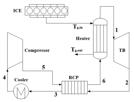
Figure 1.
Operating principle of the recuperation of a supercritical-CO2 (S-CO2) cycle. ICE: internal combustion engine, RCP: recuperator, TB: turbine and Tg,in and Tg,out: temperature increase and decrease.
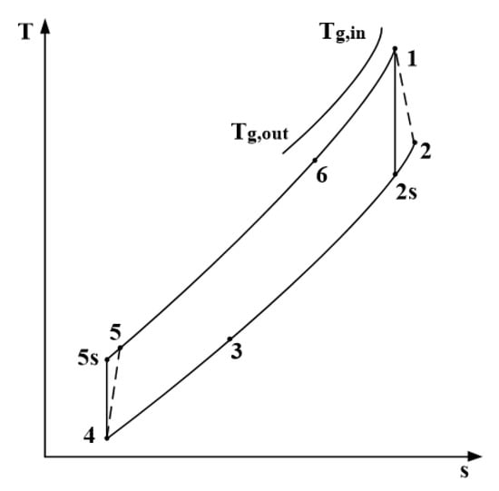
Figure 2.
Temperature-entropy (T-s) diagram of the recuperation of a S-CO2 cycle.
2.3. Pre-Compression of the S-CO2 Cycle
A single recuperation S-CO2 cycle used for a high temperature heat source cannot fully utilize the available waste heat. The turbine exhaust S-CO2 has a low specific heat, while the compressor exit S-CO2 has a high specific heat. As a result, there is a big heat transfer temperature difference in the recuperator, which will lead to large internal irreversibility. Therefore, the recuperator is divided into a low temperature recuperator (LTR) and a high temperature recuperator (HTR) in other S-CO2 cycle layouts.
Figure 3 and Figure 4 show the layout of the pre-compression S-CO2 cycle and its T-s diagram. The compression is completed in the pre-compressor (PC) and main compressor (MC), successively. The working fluid exiting the HTR is compressed from state 3 to state 4 in the PC. Compared to recuperation of the S-CO2 cycle, the working fluid pressure can be adjusted conveniently, because the pressure of the MC inlet at state 6 can be adjusted by the working fluid pressure of the turbine outlet at state 2 and the compression ratio. The pressure difference between the heat fluid and cool fluid in the LTR can be decreased, which can reduce the pinch point in the heater and decrease the internal irreversible loss.
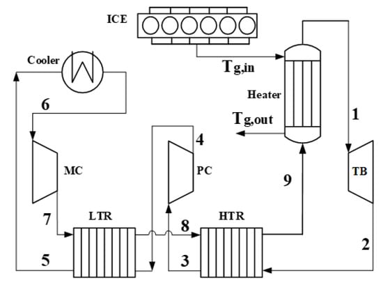
Figure 3.
Operating principle of pre-compression S-CO2 cycle. MC: main compressor, LTR: low temperature recuperator, PC: pre-compressor and HTR: high temperature recuperator.
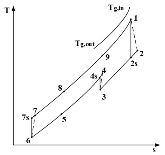
Figure 4.
T-s diagram of pre-compression S-CO2 cycle.
2.4. Split-Flow Recompression S-CO2 Cycle
The layout and T-s diagram of the split-flow recompression S-CO2 cycle are shown in Figure 5 and Figure 6, respectively. In a recompression S-CO2 cycle, the flow is split at state 4, and CO2 in the cold side with high specific heat is matched to the hot side large flow with lower specific heat in the low LTR to maximize the cycle efficiency. The fluid flow is divided into two parts at state 4, one part working fluid flows through the cooler (C), main compressor (MC), LTR, HTR and heater, successively. The other part working fluid is drawn into the re-compressor (RC) without cooling. Then, the working fluid from the MC at state 7 and LTR at state 8 are mixed at state 9. The ratio of the mass flow in the RC present in the total mass flow in the cycle is defined as the split ratio (SR).
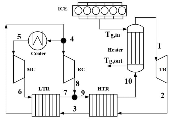
Figure 5.
Operating principle of the split-flow recompression S-CO2 cycle. RC: re-compressor.
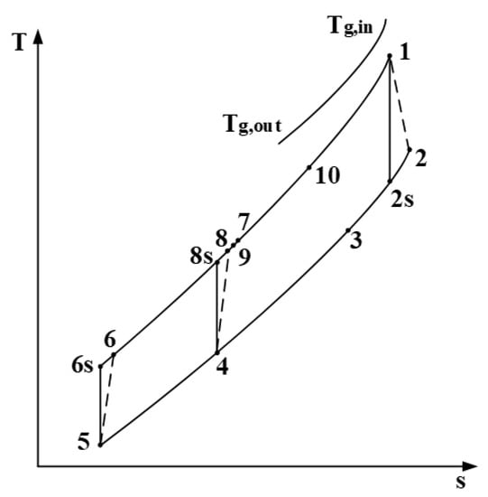
Figure 6.
T-s diagram of the split-flow recompression S-CO2 cycle.
2.5. Split-Flow Expansion of the S-CO2 Cycle
The layout of the split-flow expansion S-CO2 cycle and its T-s diagram are shown in Figure 7 and Figure 8, respectively. In this cycle, the flow is split at state 6 and then mixed at state 4. One part working fluid flowing through the LTR and heater can achieve the highest cycle temperature at state 1. Then, it flows into the turbine 1 (TB-1), and the enthalpy of working fluid is converted into work. The exhaust steam is cooled in the HTR and cooler, successively. The other part working fluid is heated in the HTR and then flows into the turbine 2 (TB-2) to do work. The exhaust gas of the TB-2 is cooled in the LTR and mixed with the first part working fluid at state 4. The ratio of the mass flow in the TB-2 present in the total mass flow in the cycle is defined as the split ratio (SR).
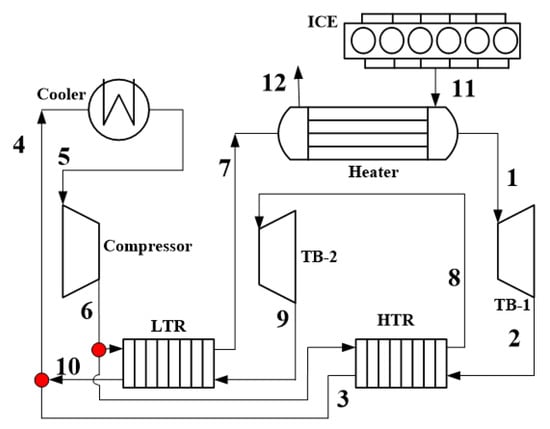
Figure 7.
Operating principle of the split-flow expansion S-CO2 cycle. TB-1 and TB-2: turbine 1 and 2.
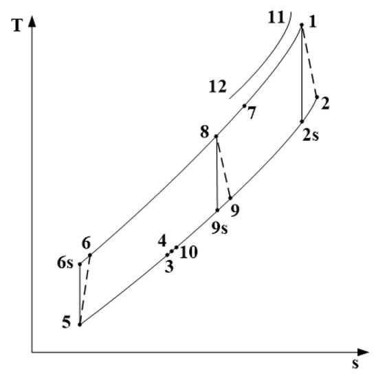
Figure 8.
T-s diagram of the split-flow expansion cycle.
3. Thermodynamic Modeling
Before establishing the mathematical model of this system, some general assumptions should be formulated, as follows: (1) All devices operate at a steady state or nearly at a steady state; the property variations with time are small enough to ignore. (2) The kinetic and potential energies are neglected. (3) The heat losses in each component and pipe are also neglected. (4) The pressure drop and entropy increase in each component and pipe are ignored for simplicity. The basic thermal physical parameters of the cycles, which are based on previous works, are shown in Table 2 [22,23]. According to those assumptions, the change of working fluid is ideal in turbomachinery, and many losses in turbomachinery are ignored so the efficiency of the turbomachinery is kept constant.
Table 2.
Thermal physical parameters of the cycles.
The thermal parameters of CO2 can be calculated through two independent parameters, and some parameters at a special state must be decided by iterative calculation. In this study, the thermodynamic calculation model for the recuperation S-CO2 cycle is introduced in detail, as follows. The set of Equations (1)–(9) correspond to the symbols and states shown in Figure 1 for the simple S-CO2 recuperation cycle.
The heat absorption capacity of CO2 is equal to the released heat of ICE exhaust, which is decided by:
where qmg is the mass flow rate of the exhaust gas of ICE and the subscripts in and out indicate the inlet and outlet states of the exhaust gas in the heater, respectively. qmco2 is the mass flow rate of the CO2 gas.
Heat rejection in the cooler is
The output power of the turbine is
The power consumption of the compressor is
where ηS,T and ηS,C are the isentropic efficiency of the turbine and compressor, respectively.
The net output power of the recuperation S-CO2 cycle is
The recuperator effectiveness is defined as
The energy balance equation for the high temperature recuperator is
The thermodynamic performance for the S-CO2 cycle could be evaluated by two parameters, thermal efficiency and the exhaust heat recovery ratio. Thermal efficiency ηt gauged the extent to which the energy input to the working fluid in the heat exchanger is converted to the net output power.
The exhaust heat recovery ratio ηre is defined as the ratio of net power output to the maximum allowable heat rate from the waste heat source [3]. It can be obtained as follows:
where h0 is the enthalpy of ICE exhaust gas at the environment temperature.
Similarly, the models for other cycle layouts can be obtained through a similar method. However, the heat transfer distribution in the LTR and HTR is unknown for the split cycle, so an iterative subroutine is necessary to obtain the heat distribution in the LTR and HTR. The calculation of the whole split recompression S-CO2 cycle is shown in Figure 9.
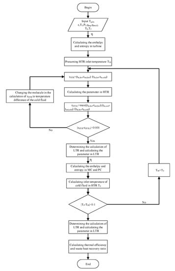
Figure 9.
The flow chart of the whole calculation process in the system.
First, the turbine outlet parameters are calculated by isentropic efficiency. Then, presuming the inlet temperature T99 at the cold side combining with the heat exchanger effectiveness ε are used to calculate the parameters of the PC, MC and LTR. Meanwhile, the new inlet temperature of the cold fluid in the HTR, T9, is calculated and compared with T99. If the difference between T9 and T99 is lower than 0.1 K, the T99 is right, else the T99 is replaced by T9. Finally, the thermal efficiency and waste heat recovery ratio are calculated by those parameters in each equipment. The heat exchanger effectiveness ε is defined as the ratio of the maximum value of cold fluid temperature difference to hot fluid temperature difference and the inlet temperature difference between the cold fluid and the hot fluid. So, when calculating the parameter of the heat exchanger, the heat exchanger effectiveness and calculation method must be considered. This process is part of the flow chart, and this process also has a judgment statement. First, the hot fluid temperature difference is presumed as the maximum temperature difference. Then, calculating the parameter of the whole system is based on this hypothesis. Finally, comparing the cold fluid temperature difference and the hot fluid temperature difference, the new heat exchanger effectiveness ε’ is calculated by the new maximum temperature difference and compared with the fixed heat exchanger effectiveness. If the difference between ε and ε’ is lower than 0.001, the hypothetical numerator is right, else the numerator is changed to the cold fluid temperature. The whole three heat exchangers must be calculated as the process including the heater, HTR and LTR. The process of other pre-compression cycles is similar to this flow chart. The recuperation cycle and the split expansion cycle need not consider the temperature of the cold fluid in the HTR.
4. Results and Discussion
4.1. Recuperation of the S-CO2 Cycle
The cycle thermal efficiency ηt and exhaust heat recovery ratio ηre of the recuperation of the S-CO2 cycle for the various compressor inlet conditions are shown in Figure 10 and Figure 11, respectively. The cycle thermal efficiency is the ratio of net power output to cycle heat absorption. The exhaust heat recovery ratio is the ratio of net power output to the maximum allowable heat rate from the waste heat source. The turbine inlet pressure is fixed at 25 MPa. It is found that at the subcritical area where the compressor inlet pressure is lower than the critical pressure 7.38 MPa, ηt and ηre increase with the rising of the compressor inlet pressure. When the compressor inlet pressure is higher than the critical pressure, ηt and ηre increase and then decrease with the rising of the compressor inlet pressure; there is an optimum compressor inlet pressure leading to the highest ηt and ηre.
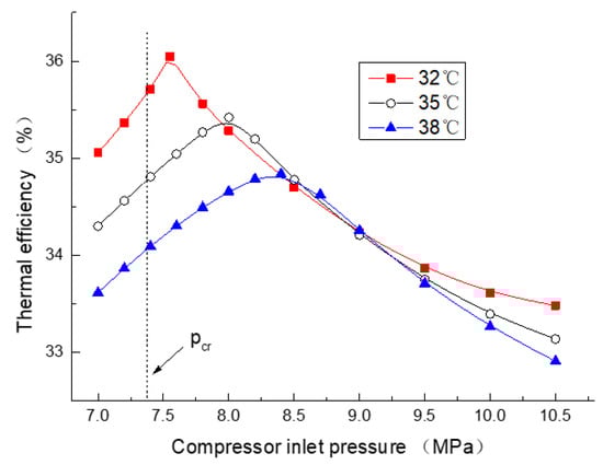
Figure 10.
Thermal efficiency for the various compressor inlet pressures and temperatures.
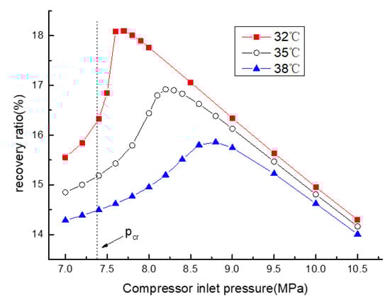
Figure 11.
The exhaust heat recovery ratio for the various compressor inlet pressures and temperatures.
ηt and ηre decrease, whereas the optimum compressor inlet pressure increases with the rising of the compressor inlet temperature, which is caused by the special pressure leading to the great change of the density that increases with the rising of the temperature. For example, the highest ηt are 36.05%, 35.42% and 34.84%, while the compressor inlet temperatures are 32 °C, 35 °C and 38 °C, respectively. Meanwhile, the according optimum compressor inlet pressures are 7.55 MPa, 8.0 MPa and 8.4 MPa, respectively. The available heat is a fixed value which is only related to the temperature of the exhaust gas and environmental temperature, so the trend of ηre is same as the trend of the net work. However, the denominator of ηt is related to the cold part outlet temperature of the RCP; the trend of enthalpy in point 6 is similar to the compressor work, which will cause the maximum ηt to appear in advance. So, it is also found that the optimum compressor inlet pressure leading to the highest ηt is lower than that leading to the highest ηre. For example, ηre can achieve the highest of 18.12% while the compressor inlet temperature is 32 °C and the optimum pressure is 7.65 MPa.
Therefore, the compressor inlet pressure must be higher than the critical pressure to achieve higher ηt and ηre. For the ICE exhaust heat recovery, parameter ηre is more important than parameter ηt. So, the optimal inlet conditions are decided to achieve the highest ηre in this paper. When the turbine inlet pressure and temperature are fixed at 25 MPa and 500 °C, the optimal compressor inlet parameters of recuperation of the S-CO2 cycle are 7.65 MPa and 32 °C, respectively.
However, ηt and ηre are not only related to the compressor inlet conditions but also related to the turbine inlet conditions. Figure 12 and Figure 13 give thermal efficiency ηt and exhaust heat recovery ratio ηre for various inlet pressures of the compressor and turbine. It is found that ηt and ηre increase while the optimal compressor inlet pressure also increases with the turbine inlet pressure, rising from 21 MPa to 29 MPa, but increases more and more slower. It is noticed that the isentropic efficiency of the turbine and compressor will decrease with the rising of pressure in actuality. Therefore, the cycle maximum pressure is limited by many factors which are not considered in this paper.
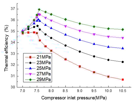
Figure 12.
Thermal efficiency for the various inlet pressures of the compressor and turbine.
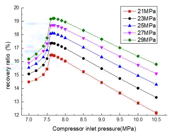
Figure 13.
Exhaust heat recovery ratio for the various inlet pressures of the compressor and turbine.
The highest ηt, ηre and corresponding compressor inlet pressure for the various turbine inlet pressures are shown in Figure 14 and Figure 15. It is shown obviously that ηt, ηre and the optimal compressor inlet pressure increase with the rising of the turbine inlet pressure. So, a suitable compressor inlet pressure could be selected to achieve the highest exhaust heat recovery ratio, which is higher than the critical pressure and increases with the rising of the turbine inlet pressure.
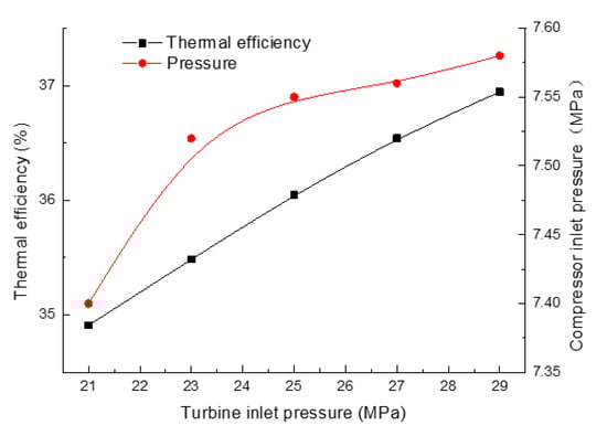
Figure 14.
The optimal thermal efficiency for various turbine inlet pressures.
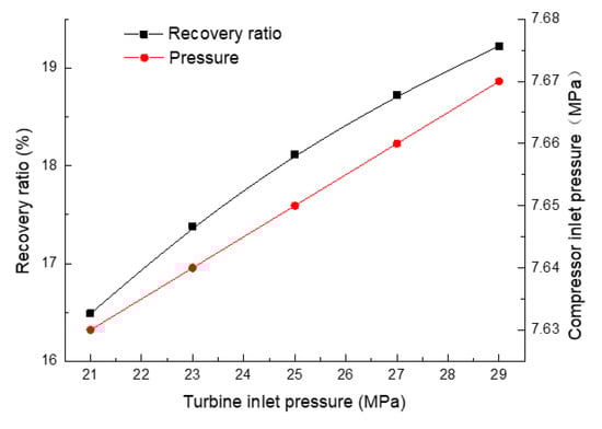
Figure 15.
The optimal exhaust heat recovery ratio for various turbine inlet pressures.
4.2. Pre-Compression S-CO2 Cycle
Figure 16 and Figure 17 show the thermal efficiency ηt and the exhaust heat recovery ratio ηre of the pre-compression S-CO2 cycle for various inlet pressures of the PC and MC. ηt changes between 37.88% and 38.80%, while ηre changes between 17.26% and 19.0%. Meanwhile, the MC/PC inlet pressures change from 7.5 MPa to 7.9 MPa and 5.6 MPa to 6.8 MPa, respectively. Both ηt and ηre increase and then decrease with the rising of the PC inlet pressure; there is an optimum PC inlet pressure leading to the highest ηt and ηre. In the calculation of the net output power, the enthalpy decided by the temperature and pressure is the important parameter. So, the net output power is determined by the expansion power in the turbine and compression power in the PC and MC. However, the changing trend of the expansion power is different from that of the compression expansion power, so there is a peak value of net output power. Meanwhile, the inlet pressure of the MC is also an important influencing factor of cycle performance, which is same as the influence of the compressor inlet pressure on recuperation of the S-CO2 cycle. The optimum PC inlet pressure is decided by the MC inlet pressure. The influence of the MC inlet pressure on ηt and ηre follows the results of recuperation of the S-CO2 cycle.
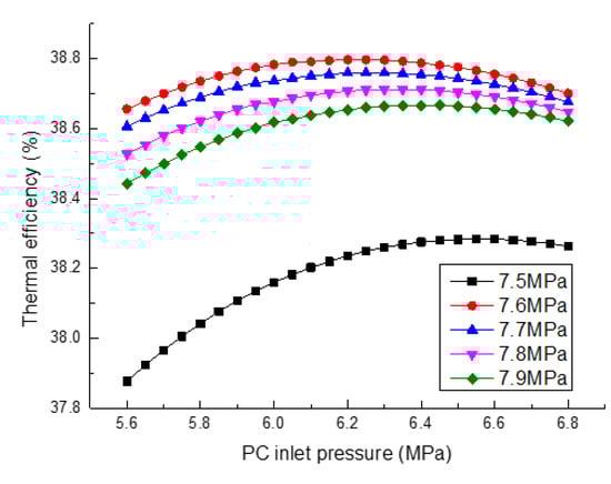
Figure 16.
Thermal efficiency for various inlet pressures of the PC and MC.
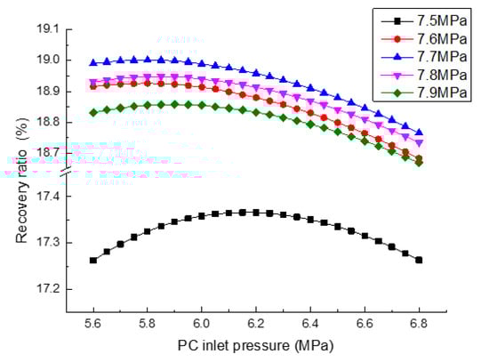
Figure 17.
Exhaust heat recovery for various inlet pressures of the PC and MC.
The highest ηt, ηre and corresponding MC/PC inlet pressure for various turbine inlet pressures are shown in Figure 18 and Figure 19. It is found that the highest ηt and ηre increase while the optimal MC/PC inlet pressures also increase, with the turbine inlet pressure rising from 21 MPa to 29 MPa. The highest ηt changes from 38.12% to 39.12%, while the corresponding MC/PC inlet pressures change from 7.54 MPa to 7.68 MPa and 6.05 MPa to 6.65 MPa, respectively. The highest ηre changes from 17.77% to 19.86%, while the corresponding MC/PC inlet pressures change from 7.66 MPa to 7.70 MPa and 5.4 MPa to 6.15 MPa, respectively. The MC/PC inlet conditions must change with the turbine inlet conditions to achieve the optimal thermodynamic performance for pre-compression of the S-CO2 cycle.
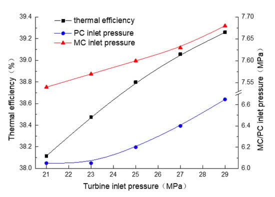
Figure 18.
Optimal thermal efficiency and corresponding MC/PC inlet pressures for various turbine inlet pressures.
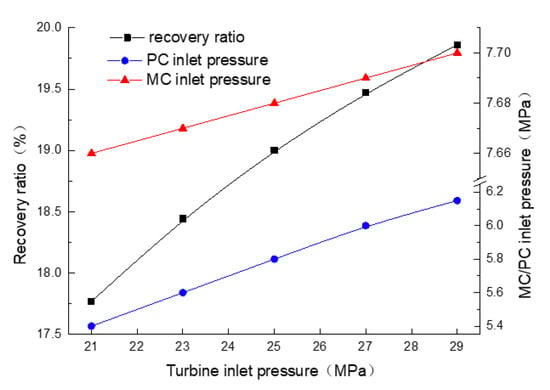
Figure 19.
Optimal exhaust heat recovery ratios and corresponding MC/PC inlet pressures for various turbine inlet pressures.
When the turbine inlet pressure and temperature are fixed at 25 MPa and 500 °C, the optimal MC/PC inlet pressures are 5.8 MPa and 7.68 MPa, respectively. It can lead to a maximum exhaust heat recovery ratio of 19.0%, while this is 18.12% of the recuperation of the S-CO2 cycle.
4.3. Split-Flow Recompression S-CO2 Cycle
For recompression of the S-CO2 cycle, the split ratio (SR) is an important parameter which can affect the thermal efficiency ηt and exhaust heat recovery ratio ηre. For various cycle pressures and temperatures, the influence of the SR on ηt and ηre is different, but the optimal cycle pressure and temperature are consistent with the recuperation of the S-CO2 cycle. Therefore, the following analysis is carried at the optimal pressure and temperature obtained from the above results based on the highest ηre.
The thermal efficiency ηt and exhaust heat recovery ratio ηre of the recompression of the S-CO2 cycle for various split ratios (SR) are shown in Figure 20, where the inlet pressures of the compressor and turbine are fixed at 7.65 MPa and 25 MPa, respectively. It is found that ηt increases and then decreases with the rising of the SR, there is an optimum SR of 0.36 leading to the highest ηt. Compared to recuperation of the S-CO2 cycle, the highest ηt increases from 36.05% to 43.16%. The results show that recompression of the S-CO2 cycle can improve cycle thermal efficiency observably. On the contrary, the exhaust heat recovery ratio ηre decreases with the rising of the SR. Since split-flow recompression has negative effects on the exhaust heat recovery, it improves thermal efficiency. Therefore, split-flow recompression of the S-CO2 cycle is not suitable to recovery of the ICE exhaust heat.
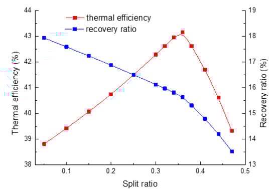
Figure 20.
Thermal efficiency and exhaust heat recovery ratios for various split ratios.
Figure 21 and Figure 22 show the thermal efficiency ηt and exhaust heat recovery ratios ηre for various split ratios and turbine inlet pressures. The optimal SR leading to the highest ηt decreases with the rising of the turbine inlet pressure, but the highest ηt is affected little by the turbine inlet pressure. The rising of the turbine inlet pressure contributes positively to the exhaust heat recovery ratio ηre, which is consistent with the results of the recuperation of the S-CO2 cycle. The rising of the turbine inlet pressure can cause rising of the enthalpy at the turbine inlet, which leads to the increase of the net output power. Meanwhile, the change trend of the net output power and heat absorbed by CO2 both changes. So, the peak of ηt moves backwards with the decreasing of the turbine inlet pressure.
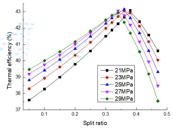
Figure 21.
Thermal efficiency for various split ratios and turbine inlet pressures.
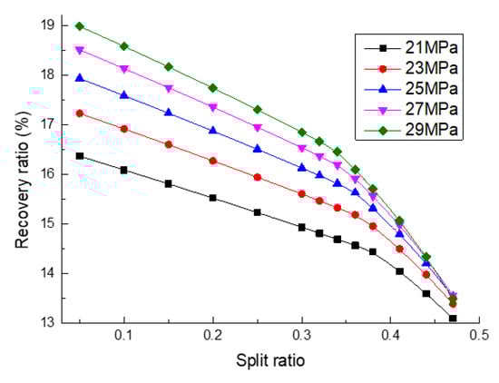
Figure 22.
Exhaust heat recovery ratios for various split ratios and turbine inlet pressures.
4.4. Split-Flow Expansion S-CO2 Cycle
The same as the recompression of the S-CO2 cycle, the optimal cycle pressure and temperature of the split-flow expansion S-CO2 cycle are also consistent with the recuperation of the S-CO2 cycle. Therefore, the thermodynamic performance is analyzed based on the results obtained from the recuperation of the S-CO2 cycle in this paper. The influence of the SR on the thermal efficiency ηt and exhaust heat recovery ratio ηre is shown in Figure 23.
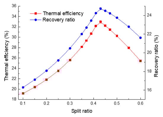
Figure 23.
Influence of the split ratio on the thermal efficiency and exhaust heat recovery ratio.
It is found that the changes of ηt and ηre with the SR are the same. Both ηt and ηre increase and then decrease with the rising of the SR; there is an optimum SR of 0.43 leading to the highest ηt and ηre. Compared to recuperation of the S-CO2 cycle, the highest ηt decreases from 36.05% to 32.99%, but the highest ηre increases from 18.09% to 24.75%. As the same as the recompression of the S-CO2 cycle, the SR will affect the output power of turbine 2 and the efficiency of the LTR and HTR. So, when considering heat exchange effectiveness, the calculations about the efficiency of the LTR and HTR must be checked. So, the curve of ηt and ηre have same trend.
Figure 24 shows the exhaust heat recovery ratios ηre for various split ratios and turbine inlet pressures. The effect of the SR on ηre for different turbine inlet pressures is the same; the ηre achieves a maximum while the SR is 0.43.
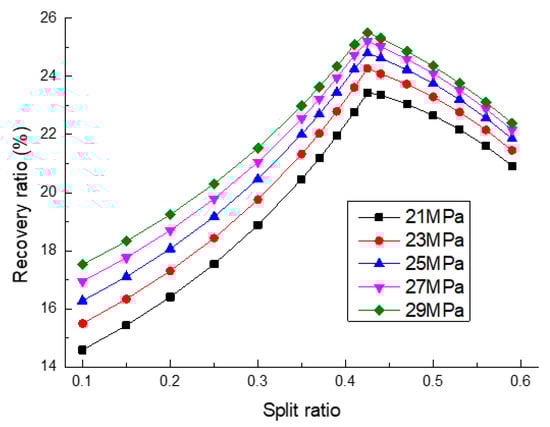
Figure 24.
Influence of split ratios on the exhaust heat recovery ratios for various turbine inlet pressures.
4.5. Performance Comparison of Various S-CO2 Cycle Layouts
Different S-CO2 cycle layouts will lead to different cycle thermodynamic performances. The cycle thermal efficiency and exhaust heat recovery ratios of various S-CO2 cycle layouts at respective optimal operation parameters are compared in Figure 25. It is shown obviously that the efficiency and exhaust heat recovery ratios of four different S-CO2 cycles have great differences with each other. For recuperation of the S-CO2 cycle, the highest ηt and ηre are 36.05% and 18.12%. For pre-compression of the S-CO2 cycle, the highest ηt and ηre are 38.8% and 19.0%. Compared to recuperation of the S-CO2 cycle, the PC can add the compression work, but the LTR and HTR can improve the inlet enthalpy of the heater and the outlet enthalpy of the turbine. So, ηt and ηre both improve. For split-flow recompression of the S-CO2 cycle, the highest ηt and ηre are 43.16% and 18.0%. For split-flow expansion of the S-CO2 cycle, the highest ηt and ηre are 32.99% and 24.75%. Compared to recompression of the S-CO2 cycle, two turbines provide higher net output powers.
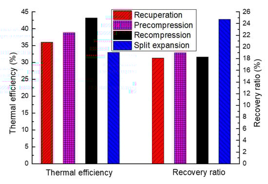
Figure 25.
Thermal efficiency and exhaust heat recovery ratios for various S-CO2 cycle layouts.
In the four S-CO2 cycle layouts, the recompression cycle and split expansion cycle can achieve the highest thermal efficiency of 43.21% and the lowest thermal efficiency of 32.99%, respectively. However, the exhaust heat recovery ratios for various S-CO2 cycle layouts are inconsistent with the thermal efficiency. The split expansion cycle and recuperation cycle can achieve the highest recovery ratio of 24.75% and the lowest recovery ratio of 18.09%, respectively. The results indicate that the split expansion S-CO2 cycle is the best layout for recovery of the internal combustion engine (ICE) exhaust energy, which is inconsistent with the conclusion given by Ahn et al. [10] and Fahad et al. [13]. The reason is that the optimal layout for obtaining the maximum power from the waste heat is different from the layout for obtaining the maximum power from the high temperature heat source. It is more important to maximize the net output power than the thermal efficiency for waste heat recovery, which is proved by Mohagheghi [15].
The output power of the ICE is 235.8 kW. Combined with the ICE and waste heat recovery, the output power of the recuperation, pre-compression, split-flow recompression and expansion S-CO2 cycles are 262.2 kW, 263.5 kW, 262.4 kW and 271.9 kW, respectively, which are shown in Figure 26. The total output power of the ICE system cycle increases 15.3% when the split expansion S-CO2 cycle is used to recover the waste heat.
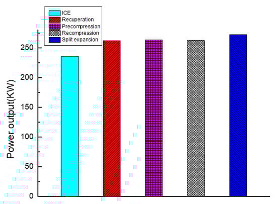
Figure 26.
Total output power of the ICE and various S-CO2 cycle layouts.
According to the comparison, the performance of the split expansion S-CO2 cycle in waste heat recovery is the best one of the four cycles. So, the split expansion S-CO2 cycle is chosen for future research, when those parameters which are influencing factors for the cycle, such as the SR, turbine temperature and turbine pressure, are fixed, the influence of pressure loss on the exhaust heat recovery ratio for various heat exchanger effectiveness is shown in Figure 27. The exhaust heat recovery ratio increases with the decrease of the pressure loss and the increase of the heat exchanger effectiveness. Since the pressure loss will result in flow losses in the pipeline, the heat exchanger effectiveness will result in heat losses in the heat exchanger.
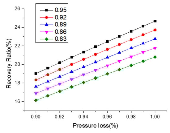
Figure 27.
Influence of pressure loss on the exhaust heat recovery ratio for various heat exchanger effectiveness.
The split-flow recompression S-CO2 cycle was better in system thermal efficiency, and thermal efficiency was an important parameter which needed be improved in the power system, so there was lots of research on the split-flow recompression S-CO2 cycle, while there was little research on the other S-CO2 cycles. However, in ICE, not only must the thermal efficiency be considered, but the waste heat recovery ratio also must be considered. It was shown that the split-flow expansion S-CO2 cycle was better in waste heat recovery, so the split-flow expansion S-CO2 cycle could be considered for ICE. Even if the thermal efficiency of the split-flow expansion S-CO2 cycle was lower than the other three cycles, it got higher output power than the other three cycles. In exchanging waste heat for output power, the split-flow expansion S-CO2 cycle had better performance, which confirmed that it was worthwhile to study the system combining the ICE and split-flow expansion S-CO2 cycle. However, for actual applications of ICE waste heat recovery, the complex cycle layouts will lead to high equipment costs, which may contribute negatively to the total system performance. There is also the waste heat of the ICE that is considered in this research, which will result in some heat losses in the whole ICE, that are not mentioned. So, the ICE waste heat recovery system needs further experimental research and economic analyses.
5. Conclusions
For recovering ICE waste heat effectively, four S-CO2 cycle layouts are brought out, and their thermodynamic performances are analyzed. The following results can be concluded from this study:
- (1)
- For the recuperation of the S-CO2 cycle considered in this study, there is the highest thermal efficiency and exhaust heat recovery ratio at a compressor inlet pressure which is slightly higher than the critical pressure. The optimal efficiency and corresponding compressor inlet pressure increase with the rising of the turbine inlet pressure. When the turbine inlet pressure and temperature are fixed at 25 MPa and 500 °C, the optimal compressor inlet parameters leading to a maximum exhaust heat recovery ratio of 18.12% are 7.65 MPa and 32 °C, respectively.
- (2)
- The MC/PC inlet pressures will change with the turbine inlet conditions to achieve the optimal thermodynamic performance of the pre-compression S-CO2 cycle. The optimal MC/PC inlet pressures are 5.8 MPa and 7.68 MPa, respectively, which can lead to a maximum exhaust heat recovery ratio of 19.0%.
- (3)
- For the split-flow recompression S-CO2 cycle, thermal efficiency increases and then decreases with the rising of the SR; there is an optimum SR of 0.36 leading to the maximum thermal efficiency of 43.16%. On the contrary, the exhaust heat recovery ratio decreases with the rising of the SR, which indicates that the split-flow recompression S-CO2 cycle is not suitable for ICE waste heat recovery.
- (4)
- Both the thermal efficiency and exhaust heat recovery ratio increase and then decrease with the rising of the SR for the split expansion S-CO2 cycle; there is an optimum SR of 0.43. Compared to recuperation of the S-CO2 cycle, the maximum highest thermal efficiency decreases from 36.05% to 32.99%, but the maximum exhaust heat recovery ratio increases from 18.09% to 24.75%. Among the four layouts considered in this study, the split expansion S-CO2 cycle can achieve the highest performance for ICE waste heat recovery, while the total output power can increase 15.3%.
Author Contributions
Conceptualization, W.Y.; data curation, D.G.; formal analysis, Q.G.; funding acquisition, X.L.; investigation, H.S.; writing—original draft, Q.G. and writing—review and editing, G.W. All authors have read and agreed to the published version of the manuscript.
Funding
This work was supported by the Open Fund Project of the Hubei Key Laboratory of Hydroelectric Machinery Design & Maintenance (NO.2019KJX05) and Research Project of Hubei Provincial Department of Education (NO. D20181206).-Yichang, China.
Conflicts of Interest
The authors declare no conflict of interest.
Abbreviations
| Nomenclature | |
| T | Temperature (°C) |
| q | Mass flow rate (kg/h) |
| W | Power (kw) |
| h | Enthalpy (kJ/kg) |
| Greek letters | |
| η | Efficiency |
| ε | Effectiveness of recuperator |
| φ | Amount of transferred heat |
| subscripts | |
| g,out | Exhaust gas at the outlet of Heater |
| 1–10 | Inlet and outlet of apparatus in the cycle |
| 0 | Exhaust gas at the environment temperature |
| S,T | Turbine isentropic efficiency |
| S,C | Compressor isentropic efficiency |
| mco2 | Mass flow rate of CO2 |
| g,in | Exhaust gas at the inlet of Heater |
| mg | Mass flow rate of exhaust gas |
| t | Thermal |
| re | Waste heat recovery |
| 2 s, 5 s | Ideal state of working fluid at points 2 and 5 |
| Abbreviations | |
| ICE | Internal combustion engine |
| S-CO2 | Supercritical Carbon Dioxide |
| SR | Split ratio |
| RCP | Recuperator |
| TB | Turbine |
| CP | Compressor |
| C | Cooler |
| HTR | High temperature recuperator |
| LTR | Low temperature recuperator |
| MC | Main compressor |
| PC | Pre-compressor |
| RC | Re-compressor |
References
- Alagumalai, A. Internal combustion engines: Progress and prospects. Renew. Sustain. Energy Rev. 2014, 38, 561–571. [Google Scholar] [CrossRef]
- Payri, F.; Olmeda, P.; Martín, J.; Carreño, R. Experimental analysis of the global energy balance in a DI diesel engine. Appl. Therm. Eng. 2015, 89, 545–557. [Google Scholar] [CrossRef]
- Kim, Y.M.; Shin, D.G.; Kim, C.G.; Cho, G.B. Single-loop organic Rankine cycles for engine waste heat recovery using both low- and high-temperature heat sources. Energy 2016, 96, 482–494. [Google Scholar] [CrossRef]
- Seyedkavoosi, S.; Javan, S.; Kota, K. Exergy-based optimization of an organic Rankine cycle (ORC) for waste heat recovery from an internal combustion engine (ICE). Appl. Therm. Eng. 2017, 126, 447–457. [Google Scholar] [CrossRef]
- Wang, X.; Shu, G.; Tian, H.; Feng, W.; Liu, P.; Li, X. Effect factors of part-load performance for various Organic Rankine cycles using in engine waste heat recovery. Energy Convers. Manag. 2018, 174, 504–515. [Google Scholar] [CrossRef]
- Benato, A.; Macor, A. Biogas Engine Waste Heat Recovery Using Organic Rankine Cycle. Energies 2017, 10, 327. [Google Scholar] [CrossRef]
- Galindo, J.; Ruiz, S.; Dolz, V.; Royo-Pascual, L.; Haller, R.; Nicolas, B.; Glavatskaya, Y. Experimental and thermodynamic analysis of a bottoming Organic Rankine Cycle (ORC) of gasoline engine using swash-plate expander. Energy Convers. Manag. 2015, 103, 519–532. [Google Scholar] [CrossRef]
- He, M.; Zhang, X.; Zeng, K.; Gao, K. A combined thermodynamic cycle used for waste heat recovery of internal combustion engine. Energy 2011, 36, 6821–6829. [Google Scholar] [CrossRef]
- Morgan, R.; Dong, G.; Panesar, A.; Heikal, M. A comparative study between a Rankine cycle and a novel intra-cycle based waste heat recovery concepts applied to an internal combustion engine. Appl. Energy 2016, 174, 108–117. [Google Scholar] [CrossRef]
- Ahn, Y.; Bae, S.J.; Kim, M.; Cho, S.K.; Baik, S.; Lee, J.I.; Cha, J.E. Review of supercritical CO2 power cycle technology and current status of research and development. Nucl. Eng. Technol. 2015, 47, 647–661. [Google Scholar] [CrossRef]
- Song, J.; Li, X.; Ren, X.; Gu, C. Performance analysis and parametric optimization of supercritical carbon dioxide (S-CO2) cycle with bottoming Organic Rankine Cycle (ORC). Energy 2018, 143, 406–416. [Google Scholar] [CrossRef]
- Wu, C.; Wang, S.; Li, J. Parametric study on the effects of a recuperator on the design and off-design performances for a CO2 transcritical power cycle for low temperature geothermal plants. Appl. Therm. Eng. 2018, 137, 644–658. [Google Scholar] [CrossRef]
- FAl-Sulaiman, A.; Atif, M. Performance comparison of different supercritical carbon dioxide Brayton cycles integrated with a solar power tower. Energy 2015, 82, 61–71. [Google Scholar] [CrossRef]
- Padilla, R.V.; Too, Y.C.S.; Benito, R.; Stein, W. Exergetic analysis of supercritical CO2 Brayton cycles integrated with solar central receivers. Appl. Energy 2015, 148, 348–365. [Google Scholar] [CrossRef]
- Mohagheghi, M.; Kapat, J. Thermodynamic optimization of recuperated S-CO2 Brayton cycles for waste heat recovery applications. In Proceedings of the 4th International Symposium-Supercritical CO2 Power Cycles, Pittsburgh, PA, USA, 9–10 September 2014. [Google Scholar]
- Jiang, P.; Zhang, F.; Xu, R. Thermodynamic analysis of a solar–enhanced geothermal hybrid power plant using CO2 as working fluid. Appl. Therm. Eng. 2017, 116, 463–472. [Google Scholar] [CrossRef]
- Lee, W.W.; Bae, S.J.; Jung, Y.H.; Yoon, H.J.; Jeong, Y.H.; Lee, J.I. Improving power and desalination capabilities of a large nuclear power plant with supercritical CO2 power technology. Desalination 2017, 409, 136–145. [Google Scholar] [CrossRef]
- Hu, L.; Chen, D.; Huang, Y.; Li, L.; Cao, Y.; Yuan, D.; Wang, J.; Pan, L. Investigation on the performance of the supercritical Brayton cycle with CO2-based binary mixture as working fluid for an energy transportation system of a nuclear reactor. Energy 2015, 89, 874–886. [Google Scholar] [CrossRef]
- Baronci, A.; Messina, G.; McPhail, S.J.; Moreno, A. Numerical investigation of a MCFC (Molten Carbonate Fuel Cell) system hybridized with a supercritical CO2 Brayton cycle and compared with a bottoming Organic Rankine Cycle. Energy 2015, 93, 1063–1073. [Google Scholar] [CrossRef]
- Park, S.; Kim, J.; Yoon, M.; Rhim, D.; Yeom, C. Thermodynamic and economic investigation of coal-fired power plant combined with various supercritical CO2 Brayton power cycle. Appl. Therm. Eng. 2018, 130, 611–623. [Google Scholar] [CrossRef]
- Zhou, J.; Zhang, C.; Su, S.; Wang, Y.; Hu, S.; Liu, L.; Ling, P.; Zhong, W.; Xiang, J. Exergy analysis of a 1000 MW single reheat supercritical CO2 Brayton cycle coal-fired power plant. Energy Convers. Manag. 2018, 173, 348–358. [Google Scholar] [CrossRef]
- Reyes-Belmonte, M.A.; Sebastián, A.; Romero, M. Optimization of a recompression supercritical carbon dioxide cycle for an innovative central receiver solar power plant. Energy 2016, 112, 17–27. [Google Scholar] [CrossRef]
- Neises, T.C. A Comparison of Supercritical Carbon Dioxide Power Cycle Configurations with an Emphasis on CSP Applications. Energy Procedia 2014, 49, 1187–1196. [Google Scholar] [CrossRef]
© 2020 by the authors. Licensee MDPI, Basel, Switzerland. This article is an open access article distributed under the terms and conditions of the Creative Commons Attribution (CC BY) license (http://creativecommons.org/licenses/by/4.0/).