Abstract
Net-shaped casting processes in the automotive industry have proved to be difficult to simulate due to the complexities of the interactions amongst thermal, fluid, and solute transport regimes in the solidifying domain, along with the interface. The existing casting simulation software lacks the necessary real-time estimation of thermophysical properties (thermal diffusivity and thermal conductivity) and the interfacial heat-transfer coefficient (IHTC) to evaluate the thermal resistances in a casting process and solve the temperature in the solidifying domain. To address these shortcomings, an axial directional solidification experiment setup was developed to map the thermal data as the melt solidifies unidirectionally from the chill surface under unsteady-state conditions. A Dilute Eutectic Cast Aluminum (DECA) alloy, Al-5Zn-1Mg-1.2Fe-0.07Ti, Eutectic Cast Aluminum (ECA) alloys (A365 and A383), and pure Al (P0303) were used to demonstrate the validity of the experiments to evaluate the thermal diffusivity (α) of both the solid and liquid phases of the solidifying metal using an inverse heat-transfer analysis (IHTA). The thermal diffusivity varied from 0.2 to 1.9 cm2/s while the IHTC changed from 9500 to 200 W/m2K for different alloys in the solid and liquid phases. The heat flux was estimated from the chill side with transient temperature distributions estimated from IHTA for either side of the mold–metal interface as an input to compute the interfacial heat-transfer coefficient (IHTC). The results demonstrate the reliability of the axial solidification experiment apparatus in accurately providing input to the casting simulation software and aid in reproducing casting numerical simulation models efficiently.
1. Introduction
The recent global requirement for lighter automotive vehicles for improving the range efficiency of fuel and mitigation of the global carbon footprint has resulted in significant research and the development of new aluminum alloys for structural components. Net-shaped casting processes, such as high-pressure and low-pressure methods in permanent metal molds, are increasingly popular for manufacturing lightweight automotive Al components due to their process efficiency and economy. Simulations of casting processes are critical in producing high-integrity structural Al castings, and these simulations include simultaneous solutions to the transient thermal, mass solute, and fluid flow fields to predict and mitigate defects, optimize processes, and ensure consistent part quality. The validity of these simulation predictions relies on the evaluation of the transient thermal resistances offered in the removal of heat from the solidifying casting in the solidifying Al alloy, mold–metal interface, and steel mold, alike. The thermal resistances in the solidifying Al alloy domain within the casting cavity are further complicated by the release of heat during solidification. The three regions of thermal resistance during the solidification of an alloy are shown in Figure 1.
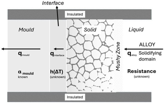
Figure 1.
Schematic representing the cross-section of a typical unidirectional axial-mode solidification of an Al alloy using a metal mold. The salient thermal resistances controlling solidification are the solidification of the alloy, interface of the alloy and mold, and mold material; all are shown.
The estimation of the domain thermal resistances, shown in Figure 1, is critical for a valid simulation of the casting process; it is carried out with transient thermal data from controlled experiments in combination with a robust inverse heat-transfer algorithm (IHTA) that iteratively estimates the interface resistance and thermal diffusivity of the solidifying domain, while including the resistance in the solid mold material as well. The thermal resistance of the mold materials is typically well known from background literature sources.
Presently, casting simulations, globally, solve for the transient temperature field in the solidifying domain by user-defined values for the thermal diffusivities of the phases during solidification for the metal and mold materials; furthermore, the interface heat-transfer coefficient (IHTC) at the mold–metal interface is also a user input in the form of a constant value or a function of temperature or fluid velocity during the filling of the casting cavity. It is known that the IHTC depends on the temperature across the mold–metal interface and velocity of the Al fluid, alike, and the casting simulation software does not currently incorporate this physical reality. These user inputs in simulations prevent the validation of the solutions for the transient thermal field in the solidifying domain; moreover, the user inputs are seldom derived from literature sources containing the Al alloys and metal mold of interest in a casting process, due to the lack of relevant prior literature in this field.
To obtain valid solutions for the thermal fields during solidification, this work presents a method for evaluating the transient thermal resistances of the solidifying domain, specifically, the thermal diffusivity (α) of the solidifying alloy and IHTC. Furthermore, the directional solidification event of the casting process shall be parsed using the results, showing the variation in the IHTC as a function of interface alloy temperature, which controls the process. A controlled laboratory experiment facility was developed and used in this study to mimic the directional solidification of the net-shaped casting processes, including the time regimes of solidification and method of directional heat removal. The outcome of this study may enable the development of predictive models for the Al alloys, which may significantly improve the casting simulation and prediction of defects and microstructure in the same.
Experiments were carried out by [1] to evaluate the thermal diffusivity (α) for Al alloys in the solid phase only by isothermal experiments on reheated alloy samples. The authors herein are not aware of any other background literature work that evaluates α for the solidifying alloy in the transient regime. The solidification of Al alloys involves an elaborate two-phase mixture regime called the mushy zone between the start of solidification at the liquidus temperature and its end at the solidus temperature. The values of α as a function of metal temperature are required for both the liquid and solid phases of the Al alloy alike, to evaluate the α in the mushy zone while incorporating the source term generated in the same from the latent heat of solidification.
There is a gap in the prior literature in evaluating α for metallic alloys during solidification, which is deemed critical for a valid casting simulation. Typically, the solidification of the aluminum alloy is assumed to follow the Schiel–Gulliver (S-G) paradigm [2,3], wherein the assumption of the complete diffusion of the solute elements in the remaining liquid phase during the mushy zone solidification is assumed at every step of temperature drop. The S-G paradigm is far removed from reality, which features solidification events with high rates of heat removal, such as in the net-shaped casting processes. Hence, the determination of the variability of fraction solid in the mushy zone solidification as a function of temperature is not constant, as in the S-G paradigm assumption, and it is necessary for it to be evaluated at every unique domain location. The Results Section of this publication provides evidence that the S-G paradigm assumption is incorrect in evaluating and parsing the solidification of Al casting alloys.
The IHTC at the mold–metal interface depends on the flux crossing the interface across a marked temperature difference between the Al alloy and H13 tool steel mold at the interface. Two common methods were suggested by [4,5] to determine the IHTC in metal solidification: the control volume technique, based on energy balance among control volumes to determine surface temperature and heat flow, and Beck’s method, a nonlinear estimation technique that uses thermal data measured from both metal and mold, which has been widely used in the casting industry.
The determination of IHTC at the metal–die interface for the HPDC of the AlSi9CuFe alloy was carried out by [6] on a casting process (uncontrolled environment) by a trial-and-error method using the simulations to verify the experiment temperature fields with several assumptions of IHTC until the temperature fields in the simulation at certain locations match with the experiments. This method is not transferable to other casting processes and is not a physics-informed solution. IHTC was determined during the investment-casting process of single-crystal blades from superalloy DD6 by [7] as a function of time and does not reflect the contribution of phase change.
The IHTC at the metal–sand mold interface was evaluated by [8] in low-pressure sand casting for ZL205A and ZL114A aluminum alloys with approximated thermophysical properties of metal and mold while assuming the S-G model for the fraction of solid and latent heat evolution for very slow cooling rates. The metal/die IHTC for HPDC B390 was estimated by [9] with the S-G model as a function of initial die surface temperature, far from high cooling rate casting conditions. The effect of the processing parameters was investigated by [10] on IHTC in HPDC on the AM60B Al alloy with the S-G model. These studies, as well, fail to reflect the reality of the physics in a metal casting process.
Controlled experiments by [11,12] estimated transient IHTC in chill mold castings as a power function of time and incorporated the interpolated values in 1-D ASE experiments. These models use the S-G model in defining the source term and do not consider the cooling rate regimes reflected in a metal casting process. The impact of die material roughness on IHTC was studied by [13]; however, they considered the S-G model for solid fraction and latent heat evolution.
The lumped capacitance method was used [14] in an evaluation of IHTC using a laboratory-scale hot chamber die-casting apparatus considering the S-G model. Rapid radial solidification [15] was carried out to estimate thermal diffusivity and thermal conductivity using the inverse heat-transfer algorithm for pure tin in laboratory-experimental setups for both solid and liquid phases, though the scalability to cast Aluminum alloys was not mentioned. An investigation of the effect of casting thickness on the IHTC and solidification of the A356 alloy in permanent mold casting was carried out by [16], with S-G model considerations. An effort was made by [17] to optimize IHTC with pressure–temperature coupled thermophysical parameters, while considering the S-G model in source term evaluation.
The IHTC as a function of time was proposed by [18], considering S-G model-defining source terms. For Al-Si sand mold casting, ref. [19] carried out correlation analyses to address the variation in IHTC during solidification that is not transferrable to other casting processes. IHTC was evaluated as a function of surface temperature [20] for pure aluminum with various copper mold coatings. The values were defined as constants for liquid and two-phase regions and as a function of the interface temperature for the solid phase and were not transferable to the cast aluminum alloys.
The lack of data from controlled solidification experiments to enable the quantification of the transient resistances to heat flow in the solidifying alloy and chill interface at the mold is the motivation to carry out this work. The evaluation of the thermal diffusivity, α, of the solidifying Al alloy and the IHTC at the chill interface, both as a function of the temperature of the solidifying alloy at the chill interface under unidirectional heat extraction, shall be presented and explained with reference to the salient solidification events in the domain.
The novelty of the present study lies in its ability to simultaneously extract the temperature-dependent thermal diffusivity α(T) and interfacial heat-transfer coefficient IHTC(T) directly from transient solidification data obtained under controlled directional heat extraction. Unlike prior works that evaluate α or IHTC independently or rely on reheated solid samples and simplified assumptions such as the Scheil–Gulliver model, the present approach integrates high-resolution thermal measurements from the ASE apparatus with a robust inverse heat-transfer algorithm. This combined methodology enables the identification of key solidification events, quantification of transient thermal resistances, and generation of experimentally validated thermal-property inputs applicable to casting simulations within comparable cooling rate regimes.
2. Experiment and Methods
A brief description of the axial solidification experiment apparatus setup, sample preparation, and measurement of thermal diffusivity using a laser flash analyzer, as well as the inverse heat-transfer analyses of transient thermal experimental data shall be presented in this section.
2.1. Axial Solidification Experiment (ASE)
The design for the upward directional (axial) solidification experiment (ASE) apparatus is shown in Figure 2. The apparatus consists of a 3D-printed sand mold with 12 K-type thermocouples arranged across the height of the mold from the chill surface. These K-type ungrounded and calibrated thermocouples were of 1 mm (0.04″) diameter with a 0.26 s time constant. The 15 mm thick copper chill plate was designed with three (3) × 1 mm (0.04″) diameter radial holes from the surface to the center (~72 mm deep) to measure the temperature in the chill surface as the metal solidifies in the mold.
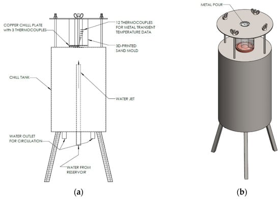
Figure 2.
Schematic of the experiment apparatus (a) for the axial unidirectional upward solidification experiment setup, and (b) isometric view of the setup showing the location for the metal pour.
The thermocouples were arranged in a helical path inside the sand mold to prevent wire overlapping and maintain uniform axial spacing throughout the height of the specimen. A fixed-depth insertion tool was used to guide each thermocouple into the mold cavity, limiting its radial deviation to approximately ±1 mm from the nominal placement at the centerline. Since the axial temperature gradient dominates the heat flow direction in the 1-D solidification configuration, the resulting radial temperature gradients were minimal. Thus, the helical arrangement does not meaningfully affect the accuracy of the temperature measurements.
The sand mold was placed on a copper plate that formed the heat-transfer interface; a controlled water jet was sprayed on the underside of this copper plate to act as a chill surface and extract heat from the mold, using a water pump with a manually adjustable globe valve. An additional thermocouple was provided at the impingement location of the water on the Cu plate mold to measure the cooling water temperature. All these thermocouples were connected to an SCXI 1102C (32-channel) data acquisition module from National Instruments, and thermal data was acquired using a LabVIEW interface program with a 100 Hz sampling frequency.
The combined measurement uncertainty of the thermocouples was estimated using a root-sum-square (RSS) method. The Type-K thermocouples used in this study comply with the Special Limits of Error (SLE) corresponding to ±1.1 °C or ±0.4% of reading. At the maximum experimental temperature of 750 °C, the ±0.4% criterion governs, giving an intrinsic uncertainty of ±3.0 °C. Additional sources of uncertainty include calibration error (±0.5 °C), the resolution of the NI SCXI-1102C data acquisition module (±0.2 °C), and thermal-lag effects associated with the 0.26 s time constant (estimated <±0.5 °C during rapid transients). Using the RSS combination of these contributions, the overall uncertainty of the temperature measurements is approximately ±3.1 °C across the experimental range.
Three popular Al alloys were used in this study, along with pure Al (P0303), as shown in Table 1. HE700 is a newly developed Al alloy [21,22], while A365 and A383 are the popular contemporary structural Al alloys used in high-pressure die-casting processes globally. The four alloy systems were selected to cover a representative range of commercial aluminum casting materials. A365 (also referred to as Aural 2 and Silafont 36) and A383 (also referred to as ADC12) are widely used ECA and complex eutectic die-casting alloys, respectively, with differing Si and Cu contents that give rise to distinctive solidification behaviors. HE700 is a newly developed DECA alloy with collaborative phase growth and unique thermal transport characteristics. Pure Al-P0303 was included as a baseline. This combination enables the validation of the ASE–IHTA methodology across alloys with significantly different microstructural evolution paths and thermal resistances during solidification. The same initial conditions were maintained for all the experiments with the Al alloys, with a 65 L per minute cooling water flow rate under the chill plate for all the alloys. For the pure Al (P0303), the cooling water flow rate was set at 30 L per minute.

Table 1.
Alloy names and compositions used for solidification experiments in this study. All numbers are expressed in weight percentages.
The alloy compositions listed in Table 1 were obtained by optical emission spectroscopy (OES) carried out at CanmetMaterials (CanmetMaterials, Natural Resources Canada (NRCan), Hamilton, ON, Canada); all values are expressed in weight percentages of the respective solute element.
About 1.3 Kg of each alloy at an initial temperature of 800 °C was poured into the ASE experiment mold, and thermal data was acquired during the solidification of the same; the thermal data was used in an IHTA program to evaluate the α and IHTC.
2.2. Laser Flash Analysis
The tokens ϕ12.7 mm × 4 mm thick for the DLF-1200 laser flash analyzer, as shown in Figure 3a, were machined and cleaned to make the surfaces free from oil and grease, allotted a unique identifier, and coated with a graphite layer before being introduced into the DLF-1200 laser flash analyzer (LFA). These tokens were precisely machined as per the manufacturer’s instructions, with necessary tolerances from the ASE cylindrical casting of HE700, A365, and pure Al (P0303). The tokens were machined such that the heat flow is perpendicular to and across the thickness of the casting sample specimen. In LFA, a laser beam is used to heat a small-area specimen maintained at a steady uniform temperature in a furnace or cryostat. A flash energy is applied with a short interval of time and compared with the resulting thermal transient measured from the temperatures observed on the back surface. Three flash energy tests were carried out at each preheated temperature, and an average of the three readings was noted. The tests were repeated for each sample token subjected to the preheat temperature range of 100 to 500 °C. The LFA method is one of the commonly used transient heat flow methods used to determine the thermal diffusivity and thermal conductivity of a solid material.
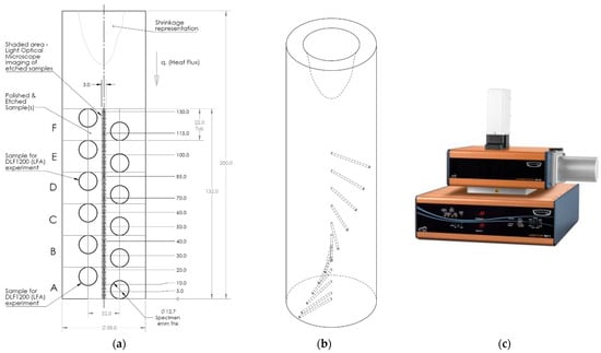
Figure 3.
Schematic of the cylindrical casting of the Al alloy from the axial unidirectional upward solidification experiment (a) showing the locations of the 12 thermocouples. Circular specimens extracted for measurement of thermal diffusivity of the solidified sample using the laser flash analyzer (LFA) and the specimens for quantitative microstructure analyses are also shown. (b) Isometric view of the casting cylinder showing the thermocouple locations in the helical path, and (c) the DLF-1200 Laser Flash Analyzer [23]. All dimensions are in mm.
2.3. Inverse Heat-Transfer Analyses
The IHTA was used for evaluating transient heat flux (q(t)), the unknown boundary condition at the copper chill plate surface at the mold–metal interface in the ASE. The thermal data from three known thermocouple locations in the copper chill plate were used as the temperature histories in the IHTA. The computational method assumes an initial guess for the unknown heat flux boundary condition (q(t)) at the metal–mold interface temperature. The one-dimensional transient heat conduction equation for the copper chill plate was solved as a direct problem with the above assumption alongside the known thermophysical properties of copper (thermal conductivity (k), density (ρ), and specific heat (c)) and the known boundary condition of the water temperature at the underside of the plate.
The temperature dependence of the mold material was considered in the analysis. For the sand mold, the thermal conductivity exhibits a mild increase with temperature, while the specific heat capacity shows a gradual upward trend within the range of interest. Conversely, the thermal conductivity of the copper chill plate decreases with increasing temperature. These temperature-dependent properties were incorporated into the numerical inverse model using tabulated data, ensuring a realistic representation of heat transfer through both the sand mold and the copper chill cast during solidification.
The process yields a calculated temperature history, Tcalc (z, t), which was compared to the experiment measurements at the various thermocouple locations. The assumed heat flux was incremented in the iterative process to minimize the sum of the squared errors between the calculated and measured temperatures.
The three thermocouples in this setup provide improved accuracy and redundancy, spatial gradient check, as well as regularize or mathematically stabilize with extra data in this ill-posed problem. Finally, the transient heat flux is translated into the interfacial heat-transfer coefficient (IHTC), hi(t), which forms a critical input for solidification simulation and modeling, and can be given by the following expression (1). While the transient mold–metal interface temperature was computed from the 12 thermocouples of the solidifying domain with the estimation of thermal diffusivity, the transient chill–metal interface temperature was estimated during the evaluation of transient heat flux from the three thermocouples in the chill plate.
The transient thermal data from the unidirectional axial solidification experimental (ASE) setup from twelve (12) thermocouples in the solidifying domain and three (3) in the copper chill plate mold were supplied as input to the inverse heat-transfer analyses (IHTAs). The initial and two boundary conditions of ASE were assigned to the IHTA for time (t) = 0 s to mimic the controlled experiment in virtual space. The flow chart shown in Figure 4 illustrates the process of estimating the thermal diffusivity as a function of temperature for each time step and for the entire domain or subdomains. These were then correlated with the cooling rates estimated from the transient thermal data during solidification. The 130 mm solidifying domain (from the top of the thermocouple to the copper plate) was discretized into 1000 elements, while the 15 mm thick copper chill plate was discretized into 500 elements. The algorithm was set to run till the sensitivity coefficient that measures the error between the measured temperatures and the temperatures predicted by the IHTA model is minimized to 10−6.
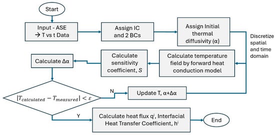
Figure 4.
A flow chart of the process methodology used in the inverse heat-transfer analyses (IHTAs).
From the transient thermal data of the ASE experiment, the thermal diffusivity was estimated in three sections for the entire domain. The Levenberg–Marquardt method (LLM) optimization algorithm systematically varies the assumed value of α until the sensitivity coefficient reaches a minimum. The three-thermocouple transient thermal data in the copper chill plate were used to estimate the heat flux for every time step passing through the mold–metal interface across the copper chill plate to the water underside of the chill plate. This transient heat flux was converted into IHTC (hi), an important parameter for solidification modeling. The thermophysical properties used in the IHTA are summarized in Table 2.
Table 2.
Thermophysical properties of materials used in the IHTA model [10,12,19,20,21,22,24].
The ASE can be reasonably approximated as a one-dimensional transient heat conduction problem, as the sand mold and top are highly insulated zones, with heat transfer in the radial direction being negligible, and the governing equation for the heat flow in the copper chill plate given as
Heat flow in the casting is similar to the above governing equation with an additional term capturing the release of the latent heat of fusion during solidification, also known as the source term
The above equation can be rewritten in finite difference terms, as follows:
Heat conducted can be defined as
In the estimation of α and q, the assumed value was changed by the small fractions “εα” and “εq”, where “ε” is a small fraction that helps in evaluating the new Tcalculated. The sensitivity coefficient for ‘q’ and ‘α’ is computed for all iterations and can be written as
For the incremental value of flux , where j is the time step, the corrected heat flux ‘q’ is given by , and corrected thermal diffusivity ‘α’ is given by . The new temperature, flux, and alpha are taken as initial inputs for the next iteration unless the correction indicates convergence.
3. Results and Discussion
Figure 5 presents a comparison between the experiment data obtained from the ASE experiments (this work) and the results of the numerical solutions to the temperature field using the explicit forward difference models; the dotted lines with data markers represent the experiment data from the 12 thermocouples placed against the direction of heat flow, from the chill plate at the mold interface, while the solid lines denote the simulated results of the thermal field in the respective thermocouple locations. The S-G paradigm for alloy solidification was used in both cases, shown in Figure 5, to define the mushy zone solidification evolution, while the IHTC was changed between a constant value, as seen in Figure 5a, and a variable function of temperature, as seen in Figure 5b, both as user inputs. Both the simulations in Figure 5 show significant deviations from the experimental data; the constant IHTC of 8000 W/m2.K predicts faster solidification of the domain, while the variable IHTC shows a significantly slower domain solidification.

Figure 5.
Typical thermal data obtained in ASE for HE700 are shown in the dashed lines with markers, along with the results of the numerical simulation of the domain in the solid lines with (a) constant and (b) variable IHTC as a function of temperature. Both cases use the Schiel–Gulliver paradigm for alloy solidification [2]—Equation (8). The alloy used for this study is the HE700 alloy.
Figure 5 demonstrates the lack of validity in the current assumptions for the transient resistance developed in the solidifying alloy domain and the chill interface at the mold, alike, and is based on Equation (9), which does not reflect reality.
Typical ASE transient thermal data for all 12 thermocouple locations (cooling curves), as shown in Figure 6, were the inputs to the IHTA algorithm. PANDATTM (PandaT software, version PanAl-2024 database, Computherm LLC., Madison, WI, USA), a CALPHAD-based materials design used to compute multicomponent phase diagrams and simulate material properties, was used to carry out non-equilibrium S-G-based solidification simulations for the alloys.
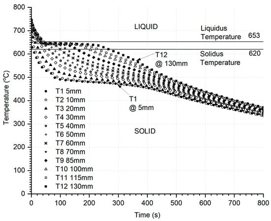
Figure 6.
Typical transient thermal data from ASE for HE700—the input to the IHTA algorithm with initial and boundary conditions reflecting the as-cast conditions in simulation. The liquidus and solidus temperatures demarcated in the graph were obtained from S-G solidification simulations.
3.1. Thermal Diffusivity
The thermal diffusivity of pure Al (P0303), A365, and HE700 samples measured in the Laser Flash Analyzer are shown in Figure 7. The thermal diffusivity for liquid and solid phases from the prior literature for pure Al (P0303), as well as Al-Fe and Al-Zn binary alloys for the solid phase, are plotted alongside the present work. The ‘α’ values for the solid phase for both HE700 and A365 were lower than those of pure Aluminum [2,24,25,26,27], and this can be attributed to the additional alloying elements. The slopes of these predicted works agree with the literature [24,25,26], with decreasing values as the temperature drops to the liquidus point.
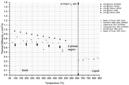
Figure 7.
Thermal diffusivity as measured from the laser flash analyses (LFAs) for the HE700, pure Al-P0303, and A365 alloys using reheated solid cast specimen of ϕ12.7 mm × 4 mm cylinders; also shown are similar data obtained for Al alloys from sources in the literature [24,25,26,27].
The ‘α’ values for the solid phase for the pure Aluminum, HE700, and A365 samples agreed with the prior literature [24,25,26,27] data from LFA and other flash-heating methods that calculate α by measuring the time it takes for the rear surface temperature of a flat plate sample to reach half of its maximum value and is commonly referred to as the half-rise time. It can be seen that thermal diffusivity increases in the solid phase with a decrease in temperature, as seen in the trend observed from the measurement of the samples from LFA, as well as in the prior literature. It should be noted that thermal diffusivity is an important thermophysical property in metals and alloys that manifests in rapidly dissipating latent heat released during solidification and is critical in the estimation of heat transfer at the mold–metal interface.
3.2. IHTA—ASE Transient Thermal Data Prediction
Cooling curves from the predicted transient thermal data from IHTA for all three alloys, HE700, pure Al-P0303, A365, and A383, are shown in Figure 8a–d, respectively. The symbols represent the ASE experimental outcome while the solid lines represent the IHTA prediction within an acceptable maximum error of less than 8%, demonstrating that the ASE analyses may provide reliable inputs for solidification simulation models.
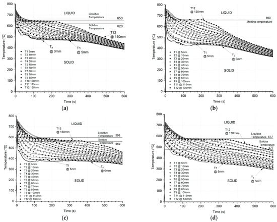
Figure 8.
Typical cooling curves from ASE—symbols from experimental data and solid lines represent the predictions from IHTA for (a) HE700, (b) pure Al (P0303), (c) A365, and (d) A383.
The liquidus and solidus temperatures were identified from the thermal analysis for these alloys, and the predicted cooling curves capture the solidification events such as liquidus, nucleation, grain growth, recalescence, and solidus points in the progressive solidification event. The mold–metal interface temperature predicted from IHTA is an important trackable parameter that helps in identifying these solidification events and translating to simulations, enhancing the accuracy of prediction.
HE700 is a dual-phase alloy with collaborative growth that inherently exhibits higher cooling rates, while A365 and A383 are polyphase alloys with sequential growth that exhibit lower cooling rates [21,22], all under similar initial thermal and cooling conditions.
3.3. Thermal Diffusivity and Interfacial Heat-Transfer Coefficient (IHTC)
The results of the analyses of the thermal data from ASE, as presented in Figure 9, show the interface temperature profile for the solidifying alloy (a) for HE700 alloys and (c) for A383 alloys as a function of time of solidification, t, and the α and IHTC for the (b) HE700 and (d) A383 alloys as a function of the temperature of the solidifying alloy at the chill interface, Tif. All the following discussions regarding the domain solidification for the HE700 and A383 alloys are for Figure 9, unless otherwise stated. The salient solidification events in the domain are demarcated as locations (A) to (G) in Figure 9, for both the HE700 and A383 alloys. Location A and the corresponding temperature at the chill interface demarcate the start of solidification of the domain, wherein the chill interface reaches the undercooled liquidus temperature of the alloy. This is about 620 °C and 570 °C for HE700 and A383, respectively, showing that there is about 30 °C and 10 °C undercooling experienced by these alloys, respectively, at the chill interface. Location G and the corresponding temperature at the chill interface demarcates the end of all solidification events in the domain, rendering it fully solid; the value of the chill interface at the end of the domain solidification is 460 °C and 350 °C for HE700 and A383, respectively. The value of IHTC between locations A and G, the start and end of solidification of the domain ranges between 4500 and 500 W/m2K for the HE700 alloy and 9000 to 400 W/m2K for the A383 alloy. Notably, the weight of both alloy castings and the cooling conditions at the chill interface by the water jet were maintained the same for these experimental results for the HE700 and A383 alloys.
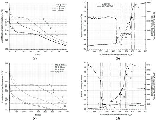
Figure 9.
Typical analyses of the thermal data from ASE. (a) and (c) show the interface temperature of the chill interface as a function of the time of solidification of the domain, along with the thermal data for thermocouples at locations 5, 50, and 130 mm for HE700 and A383, respectively. (b) and (d) show the thermal diffusivity α and IHTC in one graph as a function of the interface temperature at the chill plate for the alloys HE700 and A383, respectively, also shown at the salient solidification events starting from location A, which is the start of the solidification of the domain to location G, which is the end of solidification for each alloy.
In Figure 9, between locations A and G, the domain undergoes solidification, indicating that the solidifying alloy has two phases forming three sub-domains during this period: solid, two-phase mushy zone, and liquid. The α values of the liquid region of HE700 in Figure 9b and A383 in Figure 9d are nearly constant with respect to the change in the interface temperature and are 1.4 and 1.8 cm2/s, respectively. There is a significant drop in the α of the liquid when the chill interface region reaches the solidus temperature of the alloy, demarcated by location B, thus increasing the thermal resistance of the solidifying alloy regime as the size of the mushy zone in the solidifying domain increases. The heat coming into the chill interface from the solidifying alloy overwhelms the heat being extracted by the water jet on the Cu mold plate at location C and the respective Tif for each alloy. Beyond location C, there is an increase in the Tif for decreasing IHTC for both alloys in Figure 9b and d, respectively, due to the pile of heat in the solidifying alloy. At location D or the respective Tif, the pileup of heat at the chill interface reduces the thermal gradient ahead to below the theoretical gradient required to maintain a thermally constrained zone of solidification [2,28,29], resulting in the end of this constrained zone of solidification and the beginning of the unconstrained zone of solidification, wherein, the heat flux, including the added flux from the phase change, will be transported through a solidifying medium with a high and increasing thermal resistance, or decreasing α value, as demonstrated in Figure 9b and d for the HE700 and A383 alloys, respectively. The last liquid of the domain to solidify at the liquidus temperature is shown by location E of the respective Tif for both the alloys; the constant value of IHTC between locations D and E shows the removal of the accumulated heat at the chill interface from the solidification of the constrained regime of the solidifying domain, ending at location D for both alloys. At location E and onwards, the solidifying domain will only have two sub-domains: a two-phase mushy zone that is continuously decreasing and solid alloy that is increasing. The value of α for both the alloys drops again to its lowest value of about 0.2 cm2/s for both the alloys, notably, the same value for both cases; this lowest value of α for both alloys remains constant between the end of the liquidus temperature in the domain and the end of the solidus temperature for the duration of the disappearance of the remaining two-phase mushy zone, after location E, in both alloys. This end of solidus temperature in the alloy, indicating the end of solidification and rendering the domain into a fully one-phase solid state, occurs at location F, and the inertial effect of rendering the system back into the single-phase solid state is observed between locations F and G in both the α and IHTC curves in Figure 9b and d for HE700 and A383, respectively.
It is notable that all the solidification events of the domain could be identified in the curves for α and IHTC presented in Figure 9, and that the nature of these curves is similar in both of these alloys. The HE700 alloy is quite different in its solidification characteristics when compared to the A383 alloy. The HE700 is termed as a dilute eutectic casting alloy (DECA) and the A383 is a eutectic casting alloy (ECA) [21,22]; the HE700 alloy has a unique solidification pattern that results in two phases forming at every time step during solidification, rendering the remaining liquid during solidification back to nearly its original solute (Fe) concentration levels. In Figure 9d, two phases, the primary aluminum and the Al-Fe intermetallic phases, evolve collaboratively between locations A and G, alike. The A383 alloy solidifies sequentially, such that nearly all the primary Al phase evolves between locations A and a little past E, as seen in Figure 9d, while eutectic phases (about 55% volume fraction) evolve mostly close to location F. The effect of a large volume of eutectic solidification towards the end of solidification for the A383 alloy shows a significant inertial effect on the α curve in Figure 9d after location F as the interface temperature decreases. This effect would be the result of the transient nature of the experiment and evaluation.
The similarity in the variations in α and IHTC for the HE700 and A383 alloys shows similar trends during the solidification of the ASE domain. It is believed that this trend is predictable and could be related to the interface temperature of the solidifying alloy and used as a control factor in solving the thermal field during solidification. There is a difference between the thermal diffusivity values obtained from isothermal experiments, as shown in Figure 7, and those obtained from the ASE in Figure 9b,d; the α of the solidified samples of the alloys measured in the isothermal environment using the LFA showed lower values for the liquid and solid domains when compared to those measured during the transient regimes of solidification using IHTA. This topic is currently under perusal by the authors for a valid rationale.
4. Conclusions
Transient thermal data from ASE was used as an input to IHTA to estimate thermal diffusivity, an important thermophysical property affecting the cooling rate of the solidifying metal and its microstructure. The three thermocouples in the copper chill plate were used as inputs to the inverse heat conduction algorithm to estimate the heat flux and were translated to the interfacial heat-transfer coefficient at the mold–metal interface.
The value of α from solidified alloys in ASE, measured in the isothermal experiments using LFA for the HE700, A365, and A383 alloys and pure Al matched well with the literature background data showing the integrity of the castings. The interface temperature of the chill interface was evaluated as a function of time. The values of α and IHTC were evaluated as a function of the interface temperature of the alloy, and the salient regions and features of the solidification were parsed on these graphs. The results show that the graphs for α and IHTC for both the HE700 and A383 alloys look similar in their shapes, suggesting a common operative mechanism. However, the values of α and IHTC for the HE700 and A383 alloys were vastly different, suggesting that the alloy type has a significant effect on the resistances developed during the solidification of shaped castings. This further suggests that the α and IHTC values depend on the range of interface temperatures being operative during solidification. For the alloys examined, the thermal diffusivity exhibited values between 0.2 and 1.9 cm2/s, and the corresponding IHTC ranged from about 9500 down to 200 W/m2·K in the liquid and solid phases.
The results for α and IHTC in the transient domain indicate that the solidification in ASE is controlled by the resistance of the interface more so than that of the solidifying alloy or the metal mold chill plate. This is shown by the increase in the interface temperature for both alloys during solidification, suggesting that the rate of heat entering the interface is higher than that extracted in these regimes of solidification.
The thermal diffusivity α(T) and interfacial heat-transfer coefficient IHTC(T) obtained in this study are directly applicable to casting simulations operating within cooling rate regimes comparable to those reproduced in the ASE experiments. This includes laboratory solidification tests, gravity-cast components, and permanent mold castings where heat extraction is predominantly unidirectional. However, the applicability of these results to high-pressure die-casting (HPDC), or other high-intensity cooling processes, is limited. These processes involve different thermal conditions, including higher interfacial pressures, intense metal–die contact, rapid melt filling, gap closure/re-opening dynamics, and cooling rates far exceeding those achievable in the ASE apparatus. Consequently, the IHTC(T) and α(T) presented here should not be directly extrapolated to such processes without additional experiments performed under those specific operating conditions. Future work will focus on extending the methodology to HPDC-relevant cooling rates and pressures to establish transferable correlations for industrial simulations.
The results of α and IHTC obtained here for HE700 and A383 could be used for casting simulations of these alloys for cooling rates that fall within the range experienced in the ASE experiments.
Author Contributions
Conceptualization, R.P., M.S.H. and S.S.; methodology, R.P., A.M.T. and X.Z.; software, R.P. and A.M.T.; validation, R.P. and A.M.T.; investigation and analysis, R.P.; resources, M.S.H. and S.S.; writing—original draft, R.P.; writing—review and editing, A.M.T., M.S.H. and S.S.; supervision, M.S.H. and S.S.; project administration, S.S. and M.S.H. All authors have read and agreed to the published version of the manuscript.
Funding
Funding for this project was provided jointly by the Natural Science and Engineering Research Council (NSERC), Canada, through the Alliance grant program (File No. ALLRP 586591—23), MITACS, through their Accelerate grant program (Ref IT35357), Nemak of Canada Corporation, CanaDatum Moulds Ltd., Flow-3D, and CanmetMaterials.
Data Availability Statement
The raw data supporting the conclusions of this article will be made available by the authors on request.
Acknowledgments
The authors wish to thank the assistance provided by the Natural Science and Engineering Research Council (NSERC) of Canada through the Alliance grant program and Nemak Canada Corporation for the alloy materials. We thank CanmetMaterials, Hamilton, ON, Canada, for their support with the optical emission spectroscopy experiments for the alloys in this study.
Conflicts of Interest
The authors declare no conflicts of interest. The funders had no role in the design of the study; in the collection, analyses, or interpretation of data; in the writing of the manuscript; or in the decision to publish the results.
Nomenclature
| α | Thermal diffusivity (cm2/s) |
| ρ | Density (kg/m3) |
| c | Specific heat (kJ/(kg*K)) |
| fs | Fraction of solid |
| hi(t) | Interfacial heat-transfer coefficient (IHTC) (W/(m2*K) |
| Hf | Latent heat of fusion (kJ/kg) |
| k | Thermal conductivity (W/(m*K)) |
| km | Thermal conductivity of mold (W/(m*K)) |
| q(t) | Heat flux (W/m2) |
| t | Time (s) |
| T | Temperature (°C/K) |
| Tcf | Chill interface temperature (°C/K)—IHTA |
| Tif | Metal interface temperature (°C/K)—from IHTA |
| Tij | Calculated temperature at location zi and time tj (°C/K) |
| TL | Liquidus temperature (°C/K) |
| TS | Solidus temperature (°C/K) |
| z | Cartesian coordinate (axial) (mm) |
| Subscripts and Superscripts | |
| i | Spatial unit |
| n | Total number of iteration steps—time |
| Abbreviations | |
| ASE | Axial solidification experiment |
| DECA | Dilute eutectic cast aluminum |
| ECA | Eutectic cast aluminum |
| IHTA | Inverse heat-transfer analyses |
| IHTC | Interfacial heat-transfer coefficient |
References
- Choi, S.W.; Kim, Y.M.; Lee, K.M.; Cho, H.S.; Hong, S.K.; Kim, Y.C.; Kang, C.S.; Kumai, S. The effects of cooling rate and heat treatment on mechanical and thermal characteristics of Al–Si–Cu–Mg foundry alloys. J. Alloys Compd. 2014, 617, 654–659. [Google Scholar] [CrossRef]
- Stefanescu, D.M. Science and Engineering of Casting Solidification; Springer: Berlin/Heidelberg, Germany, 2015. [Google Scholar]
- Peres, M.D.; Siqueira, C.A.; Garcia, A. Macrostructural and microstructural development in Al–Si alloys directionally solidified under unsteady-state conditions. J. Alloys Compd. 2004, 381, 168–181. [Google Scholar] [CrossRef]
- Dhodare, A.; Ravanan, P.; Dodiya, N. A Review on Interfacial Heat Transfer Coefficient During Solidification in Casting. Int. J. Eng. Res. Technol. 2017, 6. Available online: https://www.ijert.org/a-review-on-interfacial-heat-transfer-coefficient-during-solidification-in-casting (accessed on 15 November 2025).
- Lucas, A.G.; Afshan, M.E. Heat Transfer Studies on Solidification of Casting Process. In Casting Processes and Modelling of Metallic Materials; Abdallah, Z., Aldoumani, N., Eds.; IntechOpen: London, UK, 2021. [Google Scholar]
- Long, A.; Thornhill, D.; Armstrong, C.; Watson, D. Determination of the heat transfer coefficient at the metal–die interface for high pressure die cast AlSi9Cu3Fe. Appl. Therm. Eng. 2011, 31, 3996–4006. [Google Scholar] [CrossRef]
- Dong, Y.; Bu, K.; Dou, Y.; Zhang, D. Determination of interfacial heat-transfer coefficient during investment-casting process of single-crystal blades. J. Mater. Process. Technol. 2011, 211, 2123–2131. [Google Scholar] [CrossRef]
- Zhang, A.; Liang, S.; Guo, Z.P.; Xiong, S.M. Determination of the interfacial heat transfer coefficient at the metal-sand mold interface in low pressure sand casting. Exp. Therm. Fluid Sci. 2017, 88, 472–482. [Google Scholar] [CrossRef]
- Cao, Y.; Guo, Z.; Xiong, S. Determination of the metal/die interfacial heat transfer coefficient of high pressure die cast B390 alloy. In IOP Conference Series: Materials Science and Engineering; IOP Publishing: Bristol, UK, 2012; Volume 33, p. 012010. [Google Scholar]
- Xiong, S.-M. Effect of different processing parameters on interfacial heat-transfer behavior in high-pressure die-casting process. Trans. Nonferrous Met. Soc. China 2018, 28, 2599–2606. [Google Scholar]
- Santos, C.A.; Quaresma, J.M.V.; Garcia, A. Determination of transient interfacial heat transfer coefficients in chill mold castings. J. Alloys Compd. 2001, 319, 174–186. [Google Scholar] [CrossRef]
- Muojekwu, C.A.; Samarasekera, I.V.; Brimacombe, J.K. Heat transfer and microstructure during the early stages of metal solidification. Metall. Mater. Trans. B 1995, 26, 361–382. [Google Scholar] [CrossRef]
- Liu, Z.; Wang, G.; Yi, J. Study on heat transfer behaviors between Al-Mg-Si alloy and die material at different contact conditions based on inverse heat conduction algorithm. J. Mater. Res. Technol. 2020, 9, 1918–1928. [Google Scholar] [CrossRef]
- Teamah, A.M.; Teamah, A.M.; Hamed, M.S.; Shankar, S. Experimental and Numerical Replication of Thermal Conditions in High-Pressure Die-Casting Process. Processes 2025, 13, 3815. [Google Scholar] [CrossRef]
- Basily, R.; Teamah, A.M.; Hamed, M.S.; Shankar, S. Estimation of Thermophysical Properties as Functions of Temperature in Rapid Radial Solidification of Metallic Alloys. Processes 2025, 13, 3939. [Google Scholar] [CrossRef]
- Hamasaiid, A.; Dargusch, M.S.; Dour, G. The impact of the casting thickness on the interfacial heat transfer and solidification of the casting during permanent mold casting of an A356 alloy. J. Manuf. Process. 2019, 47, 229–237. [Google Scholar] [CrossRef]
- Chang, T.; Zou, C.M.; Wang, H.W.; Wei, Z.J.; Zhang, X.J. Optimization of the interface heat transfer coefficient model based on the dynamic thermo-physical parameters in the pressure-temperature coupled field. Int. Commun. Heat Mass Transf. 2020, 110, 104435. [Google Scholar] [CrossRef]
- Ilkhchy, A.F.; Jabbari, M.; Davami, P. Effect of pressure on heat transfer coefficient at the metal/mold interface of A356 aluminum alloy. Int. Commun. Heat Mass Transf. 2012, 39, 705–712. [Google Scholar] [CrossRef]
- Kovačević, L.; Terek, P.; Kakaš, D.; Miletic, A. A correlation to describe interfacial heat transfer coefficient during solidification of Al-Si alloy casting. J. Mater. Process. Technol. 2012, 212, 1856–1861. [Google Scholar] [CrossRef]
- Kim, H.-S.; Cho, I.-S.; Shin, J.-S.; Lee, S.-M.; Moon, B.-M. Solidification parameters dependent on interfacial heat transfer coefficient between aluminum casting and copper mold. ISIJ Int. 2005, 45, 192–198. [Google Scholar] [CrossRef]
- Zheng, J. Thermal Analysis and Microstructure Investigation of Eutectic (Al-Si) and Dilute Eutectic (Al-Fe) Casting Aluminum Alloys. Master’s Dissertation, McMaster University, Hamilton, ON, Canada, 2024. [Google Scholar]
- Orji, C. Strengthening During Natural Ageing of Thin-Walled Structural Castings of (Al, Zn, Mg)-Fe Dilute Eutectic Alloy. Master’s Dissertation, McMaster University, Hamilton, ON, Canada, 2023. [Google Scholar]
- Instruments, T. Discovery Laser Flash DLF 1200. 2025. Available online: https://www.tainstruments.com/dlf-1200/ (accessed on 15 November 2025).
- Chapman, L.A.; Fry, A.T.; Roberts, S.J. Thermal Diffusivity and Thermal Conductivity Measurements on Oxide Scales; NPL: Teddington, UK, 2005. [Google Scholar]
- Mills, K.C. Recommended Values of Thermophysical Properties for Selected Commercial Alloys; Woodhead Publishing: Oxford, UK, 2002. [Google Scholar]
- Touloukian, Y.S.; Powell, R.W.; Ho, C.Y.; Nicolaou, M.C. Thermal Diffusivity. In Thermophysical Properties of Matter-The TPRC Data Series; IFI/Plenum Data Corporation: New York, NY, USA, 1974; Volume 10. [Google Scholar]
- Leitner, M.; Leitner, T.; Schmon, A.; Aziz, K.; Pottlacher, G. Thermophysical properties of liquid aluminum. Metall. Mater. Trans. A 2017, 48, 3036–3045. [Google Scholar] [CrossRef]
- Kurz, W.; Fisher, D.; Rappaz, M. Fundamentals of Solidification; Trans Tech Publications: Stafa-Zürich, Switzerland, 2023. [Google Scholar]
- Dantzig, J.A.; Rappaz, M. Solidification: Revised & Expanded; EPFL Press: Lausanne, Switzerland, 2016. [Google Scholar]
Disclaimer/Publisher’s Note: The statements, opinions and data contained in all publications are solely those of the individual author(s) and contributor(s) and not of MDPI and/or the editor(s). MDPI and/or the editor(s) disclaim responsibility for any injury to people or property resulting from any ideas, methods, instructions or products referred to in the content. |
© 2025 by the authors. Licensee MDPI, Basel, Switzerland. This article is an open access article distributed under the terms and conditions of the Creative Commons Attribution (CC BY) license.