Abstract
The process of penetration of lubricants into the frictional interface in steel machining such as turning and milling is not well revealed, which has thus compromised their machining performance. In this paper, the penetration characteristics of deionized water (Di-water) containing different electro-osmosis additives were investigated using a steel-on-steel friction pair. The worn surface lubricated with water solutions were examined using advanced surface analysis techniques. The results indicate that water lubricants were electrically driven to the frictional interface for lubrication. The addition of positive electro-osmosis additives helped promote the penetration of water solutions, thus resulting in the formation of a thick lubricating film of iron oxide at the sliding surface. This reduced abrasion damage significantly, therefore producing a lower coefficient of friction (COF) and wear loss in comparison with pure water.
1. Introduction
The control of friction and wear at the tool–workpiece interface remains a fundamental challenge in precision manufacturing processes such as turning and milling. While cutting fluids are extensively employed to mitigate thermal deformation and prolong tool service life, their efficacy is ultimately constrained by the inefficient transport of lubricants into the intimate contact zone. A critical, yet not fully understood, aspect of this problem is the physical mechanism governing lubricant penetration across the interface, which severely limits the performance gains achievable through conventional lubrication strategies.
In recent years, researchers have conducted visual studies on the penetration behavior of lubricating media during the cutting process of soft metals such as lead, aluminum, and copper by means of various transparent observation platforms, gradually revealing their microscopic transport mechanisms [1,2,3,4]. The experimental results show that, at the end of the knife–chip contact zone, dense microscale flow channels will form on the material surface. It is widely believed in the academic circle that these microstructures play a decisive role in the interfacial penetration of lubricants. They achieve the directional migration and expansion of lubricating components through capillary action, thereby facilitating the construction of an effective lubricating film. For GV through systematic characterization, it was found that this type of microchannel has a regular cylindrical structure, with an average diameter of approximately 1 μm and a length mostly concentrated in the range from 1 to 2 mm, possessing typical capillary transport geometric features [5]. Subsequent studies have indicated that, under the combined drive of capillary pressure difference and ambient air pressure, the lubricating medium can achieve directional migration along these sub-micron channels, thereby entering the contact interface [6,7]. Based on the above phenomena, Zheng et al. [8] constructed a theoretical model of gas–liquid two-phase capillary transport, revealing that the penetration depth of the lubricant is linearly positively correlated with the capillary coefficient and inversely decays with the channel diameter. Huang et al. [9] experimentally confirmed that, if the capillary action coefficient of the lubricating medium is increased, its interinterface penetration efficiency can be raised by several orders of magnitude, significantly enhancing the lubrication effect. Conversely, Liu et al. [10,11,12] focused on the lubrication mechanism of water vapor as a green cutting medium and found that it could enter the processing area driven by the pressure difference in the capillary channel, exerting both cooling and lubricating effects. Xu et al. [13] conducted a systematic investigation into the effects of capillary action, ambient pressure, and wall viscous drag on the infiltration behavior of cutting fluid during the grinding of Cr12 die steel. Their findings highlighted the coupled interplay of these factors in the penetration process. Nevertheless, the underlying mechanism governing lubricant penetration across tribological interfaces remains incompletely understood, necessitating more in-depth research.
Beyond capillary action, electrokinetic phenomena offer an alternative mechanism for fluid transport upon application of an external electric field. Electro-osmotic flow (EOF), in particular, describes the motion of an ionic fluid through a microchannel relative to a stationary charged surface. This electrohydrodynamic effect is primarily governed by the interplay between the channel’s geometry, the axial electric potential, and the structure of the electrical double layer (EDL) established at the solid–liquid interface [14]. Based on the dielectric constant ε and charge density ρ of the liquid, the Poisson–Boltzmann equation is (ψ: electric potential; ρ: charge density; ε0: dielectric constant of the medium). It can be known that the periodic electric field intensity near the wall in the liquid can further determine the adsorption force of the capillary wall on the charged particles in the solution. This is of vital importance for the study of capillary electropercolation, especially the study of the electric double layer within it. EDL development stems from capillary surface charge induction, which drives the repulsion of co-ions while attracting counter-ions to neutralize interfacial charge imbalances [15]. The resulting electrostatic interactions between Stern layer ions and the capillary’s charged surface lead to ion immobilization at the interface.
When ions within the diffuse layer of the EDL experience an axial electric field within the capillary, they migrate in a specific direction. This ion motion, coupled with the fluid’s viscosity, entrains the bulk solution, resulting in the formation of EOF [16]. As shown in Figure 1, electrophoresis (EPS) and electro-osmosis (EOS) generally exist simultaneously in the capillary, and EOS mobility is an order of magnitude larger than that of EPS [17]. The linear velocity corresponding to the EOF is expressed as [18], where is the dielectric constant of the electrolyte solution, is the electrokinetic potential (Zeta-potential) at the slipping plane, is the applied electric field, and is the solution viscosity. Electro-osmotic transport is governed by a well-defined set of scaling laws: the bulk velocity rises monotonically with both electric-field strength [19] and bulk pH [20], yet falls as the ionic strength increases [21]. Zwitterionic amphiphiles amplify this motion, whereas cationic surfactants attenuate it [22,23]. Exploiting these trends, Chen and co-workers [24,25] engineered a high-pressure micro-pump for capillary chromatography that sustains > 5 MPa while delivering microliter-per-minute flows in either water or methanol; performance is tuned simply by adjusting the terminal voltage or the channel cross-section. In related work, Wang et al. [26,27] demonstrated that imposing a controlled wall slip within microchannels can further boost flow under fixed hydraulic and electrokinetic loads. Zhong et al. [28] later measured EOF velocities of ~11 mm/s for Di water in 25 µm capillaries driven by 800 V cm−1—remarkably close to the 3.55 mm/s predicted by Liu et al. [10] for lubricant ingress into tool–chip micro-grooves. Taken together, these studies establish capillary electro-osmosis as the principal mechanism dictating how aqueous lubricants infiltrate the micro-channels formed within machining contact zones.
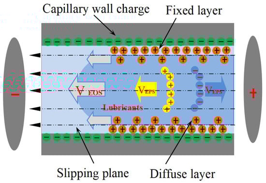
Figure 1.
Schematic diagram of an electro-osmosis mechanism.
During machining processes, the tribological interaction between contacting surfaces induces material failure through multiple mechanisms: interfacial fracturing, abrasive wear, and localized plastic flow. This dynamic degradation process exposes re-active nascent surfaces by removing the passivated oxide layer, thereby triggering electron emission phenomena. The freshly generated metallic interfaces act as electron sources due to the disruption of atomic bonds amidst material straining [29]. This phenomenon of electron emission, in combination with the electric field formed at the friction interface, significantly affects the penetration behavior of lubricants based on the principle of electroosmosis. The electric field needed in the capillary electro-osmosis of the machining zone may be produced by this electron ejection phenomenon. The friction electron ejection dominates the electron emission in the process of pin-on-disk experiment, ball-on-disk experiment, turning, and milling, etc., and the electrons are mainly emitted from the nascent machined surfaces for metal materials [30,31,32]. For example, during the friction test, two friction pairs scratched with each other and forcibly “tear” the original materials; in the meantime, there are a large number of newly emitted electrons in the worn surface gap between the friction pairs [33]. These emitted electrons are concentrated at the capillary closed end in the contact interface and spread outward at a certain speed to form electronic clusters. This electron cluster will produce an electric field directing to the inside of the capillary in the friction interface [34].
Govindaraj et al. [35] demonstrate that tribo-electron emission is governed by an interplay between the workpiece’s intrinsic characteristics—electrical resistivity, hardness, and both tensile and yield strength—and the imposed cutting conditions, namely speed and depth of cut. Their experiments on stainless steel, low-carbon steel, and copper, all machined with cemented-carbide tools, reveal that raising either cutting speed or depth amplifies emission yield, the effect being most pronounced in low-conductivity, high-strength alloys. Consequently, the electric field generated across the micro-capillaries at the tool–chip interface scales with these same parameters. An additional prerequisite for electro-osmotic transport is provided by the spontaneous charging of metallic, quartz, or other natural surfaces when immersed in aqueous media: these solids acquire a net negative charge [36], attracting the cations released by water electrolysis and thereby establishing an electrical double layer [37]. This phenomenon provides a key interface condition for the subsequent electro-osmotic effect. Considering the capillaries on the worn surface, the emitted electrons, and the EDL between the solid–liquid interfaces during the machining process, when Di-water serves as the primary lubricant, its electro-osmotic behavior within micro-capillaries likely governs lubricant penetration into the contact zone, thereby influencing overall machining performance.
Building upon this conceptual framework, the present work investigates the potential of leveraging and actively controlling electro-osmotic transport to enhance aqueous lubrication in steel-on-steel sliding contacts. To this end, a macroscopic experimental setup was first constructed to quantitatively characterize the electro-osmotic mobility of aqueous lubricants containing different functional additives (an electrokinetic promoter vs. an inhibitor) under controlled electric fields. The lubrication performance of these tailored lubricants was then rigorously evaluated using a standard four-ball tester. Furthermore, the underlying mechanisms were elucidated through a multi-scale analysis of the worn surfaces, employing scanning electron microscopy (SEM) and X-ray photoelectron spectroscopy (XPS). The overarching goal of this study is to establish a novel strategy for modulating lubricant penetration and to provide fundamental insights into the electrokinetic phenomena governing boundary lubrication.
2. Materials and Methods
2.1. Preparation of Lubricants
Deionized water (DI-water, 18.25 MΩ·cm at 25 °C) was selected as the base lubricant due to its minimal ionic interference. Two electrokinetic modifiers were investigated: a cationic surfactant, cetyltrimethylammonium bromide (CTAB, Sigma-Aldrich, City of Saint Louis, MO, USA), functioning as an electroosmotic inhibitor (EIL); and a zwitterionic surfactant, sodium lauriminodipropionate (SLI, Tokyo Chemical Industry, Tokyo, Japan), serving as an electroosmotic accelerant (EAL), as shown in Table 1. A series of solutions with additive concentrations ranging from 0.05 to 0.3 mM were prepared. To achieve complete dissolution and molecular-level dispersion, each solution was subjected to ultrasonic agitation (40 kHz, 300 W) in a thermostated water bath (25 °C) for a duration of 30 min. To guarantee statistical reliability, all measurements were conducted in quintuplicate.

Table 1.
Properties of surfactant.
2.2. CEOS Experiment
In this experiment, a custom-designed device was fabricated to simulate and quantify EOF within metal capillaries, as shown in Figure 2 [38]. The core of this device was composed of precise 304 stainless-steel capillaries, featuring two internal dimensions, inner diameters of 0.5 and 0.9 mm and outer diameters of 1.1 and 1.5 mm, to meet different microscale conditions. This capillary channel device was 40 mm long and was connected to two vertically arranged 2.5-milliliter glass syringes on both sides, serving as a reservoir and displacement monitoring device. Before each experiment, the entire fluid path underwent a strict cleaning procedure, including sequential rinsing with acetone, ethanol, and a large amount of Di-water and a 10-minute ultrasonic cleaning cycle to eliminate any organic contaminants from the capillary lumen and syringe chambers. We injected lubricant samples unilaterally via one syringe until the gravitational equilibrium leveled the menisci in both reservoirs. Each test used 1.5 mL aliquots per syringe chamber. Platinum electrodes (2 mm diameter) were placed in the terminal reservoirs; the left electrode was connected to a high-voltage generator (EST802A, Beijing Huajinghui Technology Ltd., Beijing, China) operating at 1.5 or 3 kV, while the right electrode served as the ground. The axial electric field intensity across the capillary was calculated as ~400 V/cm and ~800 V/cm for 1.5 kV and 3 kV driving potentials, respectively, surpassing the critical threshold for capillary electro-osmotic flow (CEOS) initiation (150 V/cm) [39]. Each test lasted for 30 min, and the moving volume of the liquid in the syringe was used to measure the CEOS speed of different lubricants. All experiments were conducted in five replicates under ambient temperature conditions, and the mean values of the resultant data were documented.
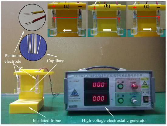
Figure 2.
Photos of the device designed for determining the electro-osmotic velocity of lubricating oil: (a) CTAB solution, (b) Di-water solution, and (c) SLI solution [38]. The test results show that the test time is 30 min, the charging voltage is 1.5 kv, and the concentration is 0.2 mm.
2.3. Tribological Evaluation of Lubricant Performance Under Varied Operational Parameters
Friction and wear tests were carried out on the MMW-1 multi-specimen test system of Jinan Shijin Group Co., Ltd. China. The tribological properties of EIL, EAL, and Di-water under different conditions were compared using the four-ball method (see Figure 3a [38]).
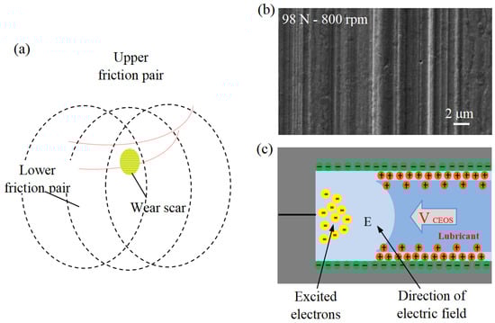
Figure 3.
(a) Schematic of four-ball test, (b) capillaries in the friction interface, and (c) schematic of friction capillary interface [38].
The friction performance was evaluated using the MMW-1 universal friction meter with standard four-ball configuration (Jinan Shijin Group, China). The upper test ball (12.7 mm diameter, AISI 52100 steel) rotates with three stationary lower balls of the same material. All the balls have undergone heat treatment and have a hardness of 59–61 HRC. The experimental matrix was designed to systematically evaluate the influence of key operating parameters such as surfactant concentration (0.05, 0.1, 0.2, 0.3 mM), rotational speed (600, 800, 1000, 1200 rpm), and external load (49, 98, 147 N). Each test was conducted at the same ambient temperature for 30 min. Before the test, all the balls underwent a strict ultrasonic cleaning in acetone for 10 min to remove surface residues and ensure reproducibility. The schematic diagram of the capillary and frictional capillary interface on its wear surface is shown in Figure 3b,c [38]. To examine the chemical states and elemental distribution across the worn surface, a dedicated ball-on-disc test was performed independently. The steel balls used are the same as those in the four-ball test. The identical steel balls employed in the four-ball tests were used in this experiment. A disc specimen, fabricated from AISI 52100 steel with dimensions of φ 32 mm (outer diameter) × φ 16 mm (inner diameter) × 0.8 mm (thickness) and a hardness of HRC 25–28, served as the counterface. Testing was carried out at ambient temperature using a lubricant additive concentration of 0.2 mM, under conditions of 800 rpm rotational speed, 98 N applied load, and a test duration of 15 min. Before the test, the sample holder and test balls/discs were soaked in acetone and ultrasonically cleaned for 10 min. All trials were performed in five independent replicates, and the mean of the obtained results was calculated and reported. After the test, both the discs and the steel balls were ultrasonically cleaned as usual. The wear scar diameter of the ball and the surface morphology of the disc were analyzed by VW-6000 three-dimensional dynamic microscope. The disc’s worn surface was characterized using scanning electron microscopy (SEM) and a Shimadzu Kratos AXIS Ultra DLD X-ray photoelectron spectrometer (XPS) with Al Kα radiation (15 keV, 10 mA). High-resolution spectra were acquired with a pass energy of 20 eV at a resolution of 0.3 eV, using the adventitious carbon C 1s peak (284.8 eV) as the binding energy reference.
3. Results and Discussion
3.1. CEOS Properties
The efficacy of the electrokinetic modifiers in altering the fundamental transport properties of the lubricants was first quantitatively established. Figure 4a,b displays the CEOS velocities for the EIL and EAL lubricants within 304 stainless-steel capillaries under varying conditions. To focus specifically on analyzing the impact of lubricant penetration on friction and wear behavior, this study adopted a scientifically justified approximation by intentionally neglecting secondary factors such as vortex characteristics within the capillaries, while emphasizing the primary mechanisms and essential features [22]. Our analysis reveals two key trends: 1. Concentration Effect: At a fixed electric field strength, CEOS velocities increased significantly for both lubricants as the surfactant concentration rose. 2. Field Strength Effect: Higher electric field intensities consistently increased CEOS velocities across all tested concentrations. Crucially, smaller capillary diameters amplified CEOS regulation, likely due to higher sidewall-to-cross-section area ratios intensifying the additives’ influence [23]. It is critical to note that the electroosmotic response saturated at approximately 0.1 mM for SLI and 0.2 mM for CTAB, suggesting the formation of a complete monolayer on the capillary surface [40,41].
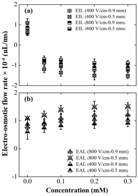
Figure 4.
Effects of surfactant type, concentration, capillary diameter, and electric field strength on CEOS flow velocity. Data points aligned with the electric field direction are denoted as positive values. All tests were conducted over a duration of 30 min. Surfactant types compared are: (a) CTAB and (b) SLI.
Figure 4 reveals a key difference: the EIL’s capillary electro-osmosis (CEOS) velocity consistently opposed the applied electric field direction. This reversal stems fundamentally from the positively charged quaternary ammonium group within CTAB molecules [42]. Electrostatic attraction drives strong CTAB adsorption onto the negatively charged capillary wall. As the CTAB concentration rises, adsorption progresses: initially forming a monolayer that progressively neutralizes the wall’s negative charge, causing CEOS to weaken and eventually cease. Crucially, upon reaching approximately 0.05 mM [39], hydrophobic interactions between CTAB tails initiate formation of a second molecular layer (Figure 5a), reversing the wall’s effective charge polarity and consequently the CEOS direction. Further concentration increases amplify this reversed flow until adsorption saturates near 0.2 mM, stabilizing the velocity. In stark contrast, EAL significantly enhanced CEOS, aligning flow with the electric field. Quantitative data highlights this effect: at ~400 V/cm, CEOS velocities surpassed Di-water by 36.9% for 0.9 mm capillary and 29.6% for 0.5 mm capillary; at ~800 V/cm, the enhancement intensified to 54.5% and 36.7%, respectively. This amplification originates in SLI’s molecular architecture (Figure 5b). Its cationic nitrogen group adsorbs firmly onto the wall, establishing an immobilized layer, while its two free carboxylic acid anions extend into the solution. This configuration effectively doubles the wall’s negative charge density, significantly strengthening the driving force for electro-osmosis [43].
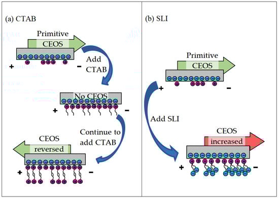
Figure 5.
Regulation mechanism of different surfactant molecules on CEOS, (a) CTAB, and (b) SLI.
3.2. Tribological Properties
3.2.1. Tribological Behaviors Under Different Concentrations
The paramount question is whether this deliberately modulated electrokinetic behavior translates directly to macroscopic tribological performance. Figure 6 compellingly demonstrates that it does. A strong, negative correlation is observed between the electroosmotic mobility (Figure 4) and the resulting coefficient of friction and wear. The SLI accelerant, which generated the strongest positive EOF, concurrently delivered the lowest friction and smallest wear scar. Its optimal performance at 0.1 mM aligns perfectly with its peak electroosmotic mobility, strongly implying that enhanced lubricant delivery is the primary mechanism for performance improvement, rather than any inherent lubricity of the surfactant itself. The inverse is true for the CTAB inhibitor, whose most detrimental tribological effects manifest at the concentration (0.2 mM) that produces the strongest flow reversal. Compared with the basic working condition, the coefficient of friction increased by 25.5%, and the wear area expanded by 10.4%. This phenomenon may stem from the adsorption behavior of cationic surfactants on the inner wall of capillaries: CTAB molecules reorganize the structure of the electrical double layer at the interface, which hinders lubricant transport to the contact zone and consequently degrades the base oil’s friction-reducing and anti-wear capabilities.
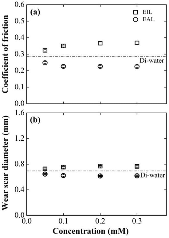
Figure 6.
Effect of surfactant concentration on (a) COF and (b) WSD for four-balls test at 800 rpm, 98 N. The results obtained using Di-water served as the baseline for comparison.
As shown in Figure 6, the tribological characteristics of the EIL/EAL system exhibit the evolution laws of COF and WSD indicators with concentration. With the increase in SLI concentration, the changes in these two parameters show a biphasic trend: a sharp decline in the initial stage and then a gradual stabilization. When the SLI concentration is 0.1 mM, the tribological performance is optimal. Compared with the benchmark value of Di-water, COF and WSD are significantly reduced by 22.7% and 10.7%, respectively. This performance improvement indicates that the EAL formula, through capillary action, can promote the deeper penetration of Di-water into the friction interface, thereby facilitating the formation of a lubricating film and enhancing the wear resistance.
Beyond this concentration threshold, further increases in additive concentration produce minimal performance improvements under both lubrication regimes. This plateau effect arises from the confluence of three interfacial phenomena: molecular adsorption saturation of CTAB/SLI on capillary surfaces (confirmed by [44,45]), maximal EDL ζ-potential attainment in capillary systems [46], and full CEOS structure development. Collectively, these mechanisms establish an interfacial equilibrium where additional additives cannot produce measurable changes in lubrication performance.
3.2.2. Tribological Behaviors Under Different Rotational Speeds
Figure 7 tracks the wear scar diameter (WSD) and friction coefficient (COF) evolution versus rotational speed for EIL and EAL lubricants, using deionized water as the baseline. Critically, both tribological parameters show velocity-dependent inversions: COF declines sharply while WSD expands progressively with the rise in the angular speed. This anti-correlated behavior mirrors Huang et al.’s [9] model for MQL/EMQL systems, linking sliding-velocity-induced contact transitions to tribological outcomes. A comparative analysis confirms EAL’s consistent superiority, maintaining lower COF and smaller WSD than EIL across all tested speeds. The performance gap peaks at 800 rpm: EAL reduces COF by 22.5%, contrasting sharply with EIL’s 25.5% increase. This divergence stems from fundamentally distinct lubricant delivery mechanisms. EAL enhances capillary-driven transport and electrostatically stabilizes boundary films, optimizing energy dissipation and wear particle control. Mechanistically, CEOS-driven penetration enables EAL to deliver more lubricant/oxygen to friction interfaces, accelerating protective oxide film formation. Conversely, EIL impedes lubricant penetration, degrading the tribological performance.
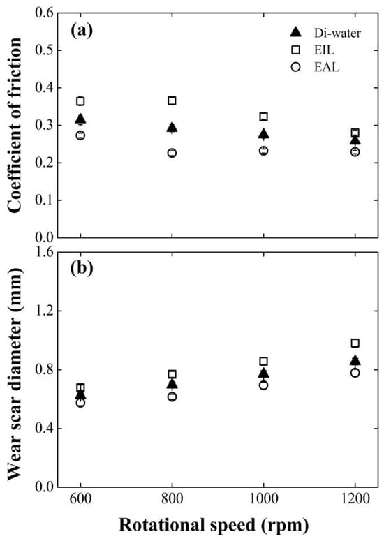
Figure 7.
Effect of rotating speed on (a) COF and (b) WSD for four-balls test at surfactant concentration of 0.2 mM, 98 N.
3.2.3. Tribological Behaviors Under Different Applied Loads
Figure 8 compares the load-dependent friction coefficient (COF) and wear scar diameter (WSD) for EAL and EIL systems against deionized water baselines. EAL demonstrates consistent tribological superiority across all tested loads, achieving substantially lower COF and WSD than EIL due to enhanced capillary-driven transport. Notably, both water and EAL exhibit biphasic COF evolution: friction initially decreases then increases with the rise in the load. This non-monotonic response reflects competing mechanisms: early load-induced capillary expansion improves penetration efficiency, while excessive loading triggers surface roughening and capillary dilation that impair fluid transport [47]. Critically, increasing normal forces intensify contact-zone triboelectrification [35], amplifying electrohydrodynamic effects that drive deeper lubricant infiltration. This enhanced delivery simultaneously replenishes boundary films and transports oxygen to wear interfaces, enabling protective tribofilm formation that optimizes energy dissipation.
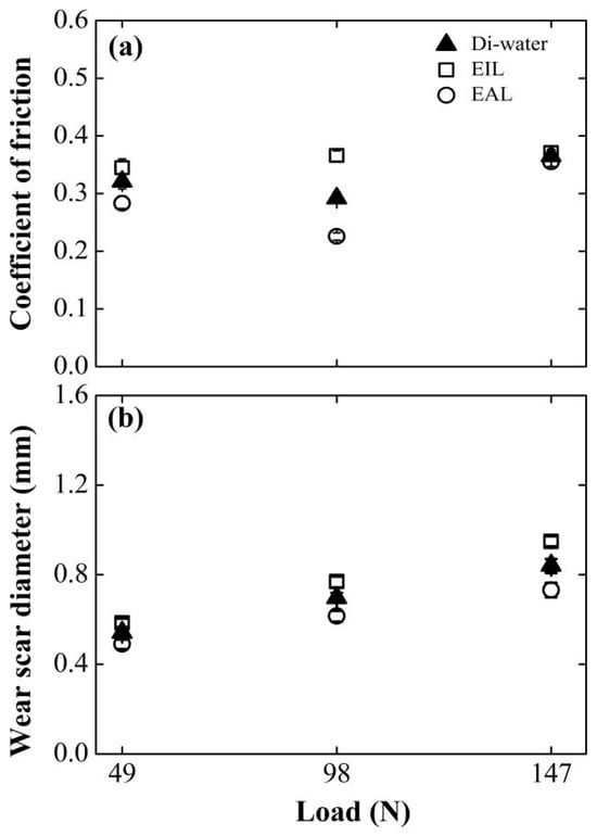
Figure 8.
Effect of applied load on (a) COF and (b) WSD for four-balls test at surfactant concentration of 0.2 mM, 800 rpm.
However, a further increase in the normal load elevated the contact pressure between the friction pairs. This led to rapid degradation of the anti-wear layer on the worn surface [48], diminished lubrication efficacy, and consequently, an elevation in the coefficient of friction (COF).
3.2.4. Surface Topography
Figure 9 presents a comparative analysis of the morphological features observed in both SEM and optical micrographs of the worn surfaces across various testing conditions. As shown in Figure 9a,c,e, the worn surfaces lubricated with SLI exhibited superior surface quality compared to those lubricated with Di-water and CTAB. This observation aligns with the corresponding friction and wear behavior. A plausible mechanism for this enhancement may be that the SLI additive promotes more efficient lubricant penetration into the contact zone, thereby accelerating the formation of a protective oxide layer on the worn surface. This oxide layer likely acted as a protective barrier, reducing surface damage and minimizing scratches, thereby enhancing surface quality. As evidenced by the SEM micrographs in Figure 9b,d,f, irregular lamellar wear debris was consistently observed across all test conditions. Furthermore, under Di-water and EIL conditions, the thin sheets peeled off uniformly, indicating the presence of adhesion and plastic deformation [49]. Meanwhile, ploughing grooves were observed on the worn surfaces to varying extents across all lubrication conditions. In summary, the wear mechanisms induced by the different lubricants involve a combination of adhesive wear, abrasive wear, and plastic deformation.
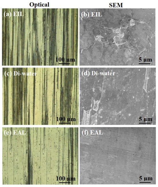
Figure 9.
Optical and SEM micrographs of the worn surfaces lubricated with (a,b) EIL, (c,d) Di-water, and (e,f) EAL at surfactant concentration of 0.2 mM, 800 rpm, and 98 N.
3.3. Lubrication Mechanism of CEOS
To investigate the lubrication mechanism of CEOS, XPS was used to analyze the worn disc surfaces, as this technique enables precise identification of surface chemical bonds and elemental states—critical for elucidating tribochemical reactions during lubrication. Figure 10 displays the XPS spectra of O 1s and Fe 2p, comparing the raw AISI 52100 steel with worn surfaces under Di-water, EIL, and EAL lubrication conditions. The spectra were fitted using XPSPEAK 41 to quantify elemental states, with their relative atomic concentrations summarized in Table 2. For the disc surfaces, O 1s spectra in Figure 10a show peaks associated with adsorbed Fe–O bonds, consistent with typical tribo-oxide formations reported in tribological studies [50]. In the Fe 2p spectra (Figure 10b), binding energies at 710.7 and 725.1 eV correspond to Fe 2p3/2 and Fe 2p1/2 of Fe2O3 and Fe3O4, while the 706.8 eV peak is attributed to Fe 2p3/2 of metallic Fe [51]. Additionally, satellite peaks at ~719.7 eV and ~732.1 eV are assigned to Fe 2p3/2 and Fe 2p1/2 satellites of Fe2O3 and Fe3O4, respectively [52,53]. These spectral features, combined with the concentration data in Table 2, lay the foundation for analyzing how CEOS influences surface chemistry during lubrication.
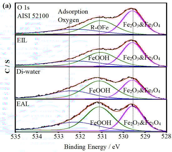
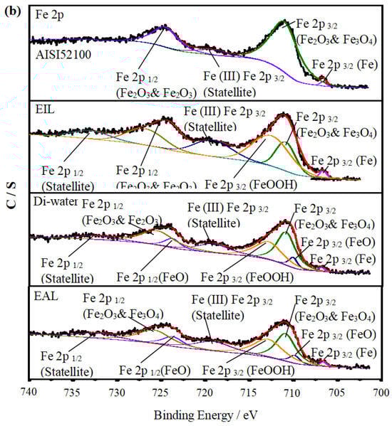
Figure 10.
XPS spectra of C 1s, Fe 2p, and O 1s on the AISI 52100 steel surface and the worn surfaces lubricated with EIL, Di-water, and EAL.
Table 2.
Relative content of C, Fe, and O and relative area of each constituent peak on AISI 52100 steel and worn surfaces produced with EIL, Di-water, and EAL.
Under EIL conditions, the CEOS was reversed, a phenomenon attributed to the formation of a secondary adsorption layer of CTAB molecules on the capillary wall—driven by intermolecular electrostatic forces. This layer reduced the CEOS effect, thereby limiting the amount of lubricant available for anti-wear processes. As observed in Figure 10b, the Fe 2p spectrum exhibits only a peak at ~711.7 eV, corresponding to Fe 2p3/2 in FeOOH. This spectral feature indicates that only a preliminary chemical reaction occurred on the worn surface, with the oxide film remaining incompletely formed. Such limited tribochemical activity aligns with the reduced anti-wear performance noted under EIL conditions, as a robust oxide layer is critical for mitigating wear in tribological systems [54].
In contrast, under EAL lubrication, new peaks corresponding to Fe 2p1/2 and Fe 2p3/2 of FeO emerged in the Fe 2p spectra. This observation implies enhanced infiltration of the lubricant into the contact region, facilitating increased oxygen supply and promoting the formation of a more substantial oxide film on the worn surface [10]. The higher oxygen content detected on the worn surface (Table 2) further promoted the oxidation of Fe0 and Fe2+ to Fe3+ [53].
As Table 2 shows, the content of O detected on the worn surface produced from EAL was higher than that from Di-water and EIL, which indicates that EAL provided the friction surface with more oxygen to accelerate the formation of an anti-wear film. In general, a protective oxide film was formed on the friction interface when EAL was employed, which enhanced the tribological performance obviously [55].
Based on the preceding experimental findings, Figure 11 proposes a model illustrating lubricant penetration behavior at the friction interface across various lubrication regimes. Di-water infiltration varied across capillary networks, leading to distinct oxide film compositions (Fe2O3/Fe3O4 and FeOOH) at the contact interface. As Gao [56] reported, these oxide films transform steel/steel contact into film/film interaction, reducing metallic adhesion. The model shows EAL enhances Di-water penetration into the contact zone more effectively than EIL, accelerating oxide film formation. This improves tribological performance by reducing interfacial shear stress and wear, consistent with observed friction and wear resistance trends.
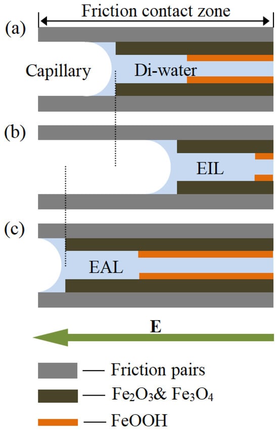
Figure 11.
Schematic illustrations of the lubricating layer under (a) Di-water, (b) electro-osmotic inhibitor lubricant, and (c) electro-osmosis accelerant lubricant conditions.
4. Conclusions
In this paper, the CEOS velocity of deionized water (Di-water), electro-osmosis accelerant (EAL), and electro-osmosis inhibitor (EIL) in 304 stainless-steel capillaries with different inner diameters under different driving voltages was verified by the capillary electro-osmosis test. And the lubrication property of these three kinds of lubricants was verified by the four-ball experiment of steel/steel contact pairs. The results show that the interfacial contact region of the test balls meets the condition of capillary electro-osmosis, and the tribological performances of the three lubricants are in agreement with the findings from the capillary electro-osmosis velocity. Furthermore, the lubrication mechanism of Di-water as lubricants based on CEOS was also revealed. The conclusions obtained and outlook for the future are the following:
- The presence and strength of CEOS in the friction interface can be effectively regulated by incorporating specific electro-osmosis regulators (such as the amphoteric surfactant SLI or cationic CTAB) into Di-water. These additives modulate the surface charge and wetting properties of micro-capillaries, thereby controlling the penetration depth and direction of the lubricant. Furthermore, process parameters such as rotational speed and load also influence CEOS intensity by affecting both electron emission and capillary morphology, with an optimal balance achieved at 800 rpm and 98 N.
- The application of EAL, notably those containing optimized additives like SLI, significantly enhances tribological performance by promoting the formation of a dense oxide layer (Fe2O3/Fe3O4) at the interface. This transforms the contact nature from metal-to-metal to oxide-to-oxide, resulting in a substantial reduction in friction coefficient and wear. These findings establish a foundational principle for designing advanced lubrication systems, offering a sustainable pathway—through reduced fluid consumption, improved surface quality, and elimination of hazardous additives for modernizing traditional industrial machining processes.
- This study verifies the feasibility of water-based lubricants combined with trace electro-osmotic additives, demonstrating outstanding advantages in energy savings, emission reduction, and health-friendly properties. Follow-up efforts should focus on expanding and optimizing such additive systems, promoting low-toxicity and biodegradable formulations, conducting full-process application validation and lifecycle assessments, and advancing this technology as an effective pathway for the green transformation of traditional machining industries.
- The research on electro-osmotic regulation in lubrication not only provides innovative theoretical and technical support for the manufacturing industry but also indicates broad prospects for commercial application. In the future, this technology is expected to become a key driving force for green intelligent manufacturing, creating new market growth points in high-end equipment manufacturing, precision machining, and environmentally friendly industries. By combining intelligent monitoring and control systems, achieving the precise management of the lubrication process will significantly reduce production costs and improve product quality, bringing revolutionary changes to traditional manufacturing. Additionally, as global environmental regulations tighten and market demand for sustainable development grows, electro-osmotic lubrication technology, with its significant energy-saving and emission-reduction advantages, hope gain wider recognition and application in the international market, enhancing the core competitiveness of related industries.
Author Contributions
Conceptualization, X.X. and B.F.; methodology, B.F.; software, X.G.; validation, X.X., G.Z. and Z.T.; formal analysis, B.F.; investigation, B.F.; resources, X.X.; data curation, G.Z.; writing—original draft preparation, B.F.; writing—review and editing, X.X. and C.Y.; visualization, X.G.; supervision, Z.T.; project administration, Z.T.; funding acquisition, B.F. All authors have read and agreed to the published version of the manuscript.
Funding
The work was sponsored by National Key R&D Program Project (No. 2025YFE0102900), the National Natural Science Foundation of China (No. 52376037), the Key Research and Development Program of Zhejiang Province (No. 2025C02030), and the Nanxun Scholars Program for Young Scholars of ZJWEU: RC2022021117.
Data Availability Statement
The data used to support the findings of this study are available from the corresponding author upon request.
Conflicts of Interest
Author Chen Yang was employed by the company Hangzhou Borong Science and Technology Co., Ltd. The remaining authors declare that the research was conducted in the absence of any commercial or financial relationships that could be construed as a potential conflict of interest.
References
- Madhavan, V.; Chandrasekar, S.; Farris, T.N. Direct observations of the chip-tool interface in the low speed cutting of pure metals. J. Tribol. 2002, 124, 617–626. [Google Scholar] [CrossRef]
- Hwang, J. Direct Observation of Fluid Action at the Chip-Tool Interface in Machining. Int. J. Precis. Eng. Man. 2014, 15, 2041–2049. [Google Scholar] [CrossRef]
- Hwang, J.; Chandrasekar, S. Contact Conditions at the Chip-Tool Interface in Machining. Int. J. Precis. Eng. Man. 2011, 12, 183–193. [Google Scholar] [CrossRef]
- Ackroyd, B.; Chandrasekar, S.; Compton, W.D. A model for the contact conditions at the chip-tool interface in machining. J. Tribol. 2003, 125, 649–660. [Google Scholar] [CrossRef]
- Godlevski, V.A.; Volkov, A.V.; Latyshev, V.N.; Maurin, L.N. The kinetics of lubricant penetration action during machining. Lubr. Sci. 1997, 9, 127–140. [Google Scholar] [CrossRef]
- Bierla, A.; Fromentin, G.; Minfray, C.; Martin, J.M.; Le Mogne, T.; Genet, N. Mechanical and physico-chemical study of sulfur additives effect in milling of high strength steel. Wear 2012, 286, 116–123. [Google Scholar] [CrossRef]
- Smith, T.; Naerheim, Y.; Lan, M.S. Theoretical analysis of cutting fluid interaction in machining. Tribol. Int. 1988, 21, 239–247. [Google Scholar] [CrossRef]
- Zhenga, W.; Pei, H.; Wang, G.; Shen, C. A Theoretical Investigation on the Capillary Model of Lubricant Penetration. Adv. Mater. Res. 2012, 383–390, 3871–3875. [Google Scholar] [CrossRef]
- Huang, S.; Wang, Z.; Yao, W.; Xu, X. Tribological evaluation of contact-charged electrostatic spray lubrication as a new near-dry machining technique. Tribol. Int. 2015, 91, 74–84. [Google Scholar] [CrossRef]
- Liu, J.Y.; Liu, H.P.; Han, R.D.; Wang, Y. The study on lubrication action with water vapor as coolant and lubricant in cutting ANSI 304 stainless steel. Int. J. Mach. Tool. Manuf. 2010, 50, 260–269. [Google Scholar]
- Liu, J.Y.; Han, R.D.; Zhang, L.; Guo, H.B. Study on lubricating characteristic and tool wear with water vapor as coolant and lubricant in green cutting. Wear 2007, 262, 442–452. [Google Scholar] [CrossRef]
- Liu, J.Y.; Han, R.D.; Sun, Y.F. Research on experiments and action mechanism with water vapor as coolant and lubricant in Green cutting. Int. J. Mach. Tool. Manuf. 2005, 45, 687–694. [Google Scholar] [CrossRef]
- Xu, X.F.; Feng, B.H.; Huang, S.Q.; Luan, Z.Q.; Niu, C.C.; Lin, J.B.; Hu, X. Capillary penetration mechanism and machining characteristics of lubricant droplets in electrostatic minimum quantity lubrication (EMQL) grinding. J. Manuf. Process 2019, 45, 571–578. [Google Scholar] [CrossRef]
- Ren, C.L.; Li, D.Q. Improved understanding of the effect of electrical double layer on pressure-driven flow in microchannels. Anal. Chim. Acta 2005, 531, 15–23. [Google Scholar] [CrossRef]
- van der Wouden, E.J.; Heuser, T.; Hermes, D.C.; Oosterbroek, R.E.; Gardeniers, J.G.E.; van den Berg, A. Field-effect control of electro-osmotic flow in microfluidic networks. Colloid. Surf. A 2005, 267, 110–116. [Google Scholar] [CrossRef]
- Zeng, S.L.; Chen, C.H.; Mikkelsen, J.C.; Santiago, J.G. Fabrication and characterization of electroosmotic micropumps. Sens. Actuat. B-Chem. 2001, 79, 107–114. [Google Scholar] [CrossRef]
- Cetin, B.; Travis, B.E.; Li, D. Analysis of the electro-viscous effects on pressure-driven liquid flow in a two-section heterogeneous microchannel. Electrochim. Acta 2008, 54, 660–664. [Google Scholar] [CrossRef]
- Wang, W.; Zhou, F.; Zhao, L.; Zhang, J.R.; Zhu, J.J. Measurement of electroosmotic flow in capillary and microchip electrophoresis. J. Chromatogr. A 2007, 1170, 1–8. [Google Scholar] [CrossRef]
- Sazelova, P.; Kasicka, V.; Koval, D.; Prusik, Z.; Fanali, S.; Aturki, Z. Control of EOF in CE by different ways of application of radial electric field. Electrophoresis 2007, 28, 756–766. [Google Scholar] [CrossRef]
- Razunguzwa, T.T.; Timperman, A.T. Fabrication and characterization of a fritless microfabricated electroosmotic pump with reduced pH dependence. Anal. Chem. 2004, 76, 1336–1341. [Google Scholar] [CrossRef]
- Issaq, H.J.; Atamna, I.Z.; Muschik, G.M.; Janini, G.M. The Effect Of Electric-Field Strength, Buffer Type And Concentration on Separation Parameters In Capillary Zone Electrophoresis. Chromatographia 1991, 32, 155–161. [Google Scholar] [CrossRef]
- Liang, Y.Y.; Weihs, G.F.; Fletcher, D.F. CFD study of the effect of unsteady slip velocity waveform on shear stress in membrane systems. Chem. Eng. Sci. 2018, 192, 16–24. [Google Scholar] [CrossRef]
- You, H. Electroosmosis and Its Application in Chromatography; Science Press: Beijing, China, 2010. [Google Scholar]
- Chen, L.X.; Ma, J.P.; Guan, Y.F. An electroosmotic pump for packed capillary liquid chromatography. Microchem. J. 2003, 75, 15–21. [Google Scholar] [CrossRef]
- Chen, L.X.; Ma, J.P.; Tan, F.; Guan, Y.F. Generating high-pressure sub-microliter flow rate in packed microchannel by electroosmotic force: Potential application in microfluidic systems. Sens. Actuat. B-Chem. 2003, 88, 260–265. [Google Scholar] [CrossRef]
- Wang, L.; Wu, J.K. Flow behavior in microchannel made of different materials with wall slip velocity and electro-viscous effects. Acta Mech. Sin. 2010, 26, 73–80. [Google Scholar] [CrossRef]
- Wang, L.; Wu, J.K. Periodical Pressure-Driven Flows In Microchannel with Wall Slip Velocity And Electro-Viscous Effects. J. Hydrodyn. 2010, 22, 829–837. [Google Scholar] [CrossRef]
- Zhong, W.; Chen, Y. Numerical simulation of hydrodynamics of capillary electroosmosis micropump. Chin. J. Mech. Eng. 2004, 40, 73–77. [Google Scholar] [CrossRef]
- Ciniero, A.; Le Rouzic, J.; Baikie, I.; Reddyhoff, T. The origins of triboemission—Correlating wear damage with electron emission. Wear 2017, 374, 113–119. [Google Scholar] [CrossRef]
- Molina, G.J.; Furey, M.J.; Kajdas, C. A deterministic-chaos study of electron triboemission outputs. J. Tribol. 2007, 129, 679–683. [Google Scholar] [CrossRef]
- Molina, G.J.; Furey, M.J.; Ritter, A.L.; Kajdas, C. Triboemission from alumina, single crystal sapphire, and aluminum. Wear 2001, 249, 214–219. [Google Scholar] [CrossRef]
- Nakayama, K.; Suzuki, N.; Hashimoto, H. Triboemission of Charged-Particles and Photons from Solid-Surfaces during Frictional Damage. J. Phys. D Appl. Phys. 1992, 25, 303–308. [Google Scholar] [CrossRef]
- Nakayama, K.; Nevshupa, R.A. Effect of dry air pressure on characteristics and patterns of tribomicroplasma. Vacuum 2004, 74, 11–17. [Google Scholar] [CrossRef]
- Kajdas, C.K. Importance of the triboemission process for tribochemical reaction. Tribol. Int. 2005, 38, 337–353. [Google Scholar] [CrossRef]
- Govindaraj, J.; Subbiah, S. Charged-Particle Emissions During Material Deformation, Failure and Tribological Interactions of Machining. J. Tribol. 2019, 141, 031101. [Google Scholar] [CrossRef]
- Lee, J.; Moon, H.; Fowler, J.; Schoellhammer, T.; Kim, C.J. Electrowetting and electrowetting-on-dielectric for microscale liquid handling. Sens. Actuat. A-Phys. 2002, 95, 259–268. [Google Scholar] [CrossRef]
- Jiang, H.Y.; Wang, Y.; Jiang, T. Research on the Microfluidics Control Method Based on the EOF Technology. Mater. Sci. Forum 2006, 532–533, 65–68. [Google Scholar] [CrossRef]
- Feng, B.; Luan, Z.; Zhang, T.; Liu, J.; Hu, X.; Guan, J.; Xu, X. Capillary electroosmosis properties of water lubricants with different electroosmotic additives under a steel-on-steel sliding interface. Friction 2022, 10, 1019–1034. [Google Scholar] [CrossRef]
- Chen, Y. Capillary Electrophoresis and Its Application; Chemical Industry: Beijing, China, 2006. [Google Scholar]
- Gaspar, A.; Gabor, L. Study of quantitative analysis of traces in low-conductivity samples using capillary electrophoresis with electrokinetic injection. J. Chromatogr. A 2005, 1091, 163–168. [Google Scholar] [CrossRef]
- Teixeira, W.S.R.; Santos, M.S.F.; Gruber, J.; Gutz, I.G.R.; Lopes, F.S. Determination of neutral diols and carboxylic acids formed during glycerol electrooxidation by capillary electrophoresis with dual (CD)-D-4. Talanta 2018, 178, 1040–1045. [Google Scholar] [CrossRef]
- Wang, W.; Zhao, L.; Zhang, J.R.; Zhu, J.J. Indirect amperometric measurement of electroosmotic flow rates and effective mobilities in microchip capillary electrophoresis. J. Chromatogr. A 2007, 1142, 209–213. [Google Scholar] [CrossRef] [PubMed]
- Tyle, P.; Frank, S.G. Penetration Temperatures of Aqueous Sodium Lauriminodipropionate Solutions into Solid Phytosterols. J. Pharm. Sci. 1991, 80, 201. [Google Scholar] [CrossRef]
- Wojciechowski, K.; Linek, K. Anion selectivity at the aqueous/polymeric membrane interface: A streaming current study of potentiometric Hofmeister effect. Electrochim. Acta 2012, 71, 159–165. [Google Scholar] [CrossRef]
- Stastna, M.; Kahle, V.; Slais, K. Automated instrumentation for miniaturized displacement electrophoresis with on-column photometric detection. J. Chromatogr. A 1996, 730, 261–272. [Google Scholar] [CrossRef]
- Paruchuri, V.K.; Nguyen, A.V.; Miller, J.D. Zeta-potentials of self-assembled surface micelles of ionic surfactants adsorbed at hydrophobic graphite surfaces. Colloid. Surf. A 2004, 250, 519–526. [Google Scholar] [CrossRef]
- Hu, Z.M.; Dean, T.A. A study of surface topography, friction and lubricants in metalforming. Int. J. Mach. Tool. Manuf. 2000, 40, 1637–1649. [Google Scholar] [CrossRef]
- Ferreira, R.O.; Galvani, G.B.; Tertuliano, I.S.; Rodrigues, A.C.P.; Azevedo, C.R.F. Characterization and evolution of the coefficient of friction during pin on disc tribotest: Comparison between C10200 Cu, AA6082-T6 Al and C36000 brass pins under varying normal loads. Tribol. Int. 2019, 138, 403–414. [Google Scholar] [CrossRef]
- She, D.S.; Yue, W.; Du, Y.J.; Fu, Z.Q.; Wang, C.B.; Liu, J.J. Vacuum Tribological Properties of Titanium with a Nanocrystalline Surface Layer. Tribol. Lett. 2015, 57, 1. [Google Scholar] [CrossRef]
- Dendaas, H.; Passacantando, M.; Lozzi, L.; Santucci, S.; Picozzi, P. The Interaction of Cu(100)-Fe Surfaces with Oxygen Studied by X-Ray Photoelectron-Spectroscopy. Surf. Sci. 1994, 317, 295–302. [Google Scholar] [CrossRef]
- Roosendaal, S.J.; van Asselen, B.; Elsenaar, J.W.; Vredenberg, A.M.; Habraken, F.H.P.M. The oxidation state of Fe(100) after initial oxidation in O2. Surf. Sci. 1999, 442, 329–337. [Google Scholar] [CrossRef]
- Mills, P.; Sullivan, J.L. Study of the core level electrons in iron and its three oxides by means of X-ray photoelectron spectroscopy. J. Phys. D-Appl. Phys. 1983, 16, 723–732. [Google Scholar] [CrossRef]
- Yamashita, T.; Hayes, P. Analysis of XPS spectra of Fe2+ and Fe3+ ions in oxide materials. Appl. Surf. Sci. 2008, 254, 2441–2449. [Google Scholar] [CrossRef]
- Hu, Y.H.; Liu, W.M. Tribological properties of alcohols as lubricating additives for aluminum-on-steel contact. Wear 1998, 218, 244–249. [Google Scholar]
- Gao, C.P.; Guo, G.F.; Zhao, F.Y.; Wang, T.M.; Jim, B.; Wetzel, B.; Zhang, G.; Wang, Q.H. Tribological behaviors of epoxy composites under water lubrication conditions. Tribol. Int. 2016, 95, 333–341. [Google Scholar] [CrossRef]
- Gao, C.P.; Fan, S.G.; Zhang, S.M.; Zhang, P.Y.; Wang, Q.H. Enhancement of tribofilm formation from water lubricated PEEK composites by copper nanowires. Appl. Surf. Sci. 2018, 444, 364–376. [Google Scholar] [CrossRef]


Disclaimer/Publisher’s Note: The statements, opinions and data contained in all publications are solely those of the individual author(s) and contributor(s) and not of MDPI and/or the editor(s). MDPI and/or the editor(s) disclaim responsibility for any injury to people or property resulting from any ideas, methods, instructions or products referred to in the content. |
© 2025 by the authors. Licensee MDPI, Basel, Switzerland. This article is an open access article distributed under the terms and conditions of the Creative Commons Attribution (CC BY) license (https://creativecommons.org/licenses/by/4.0/).