Abstract
Emergency diesel is prone to degradation during long-term storage, and experimental evaluations are costly and slow. Three-dimensional computational fluid dynamics (CFD) simulations were employed to model the diesel conditioning process. A physical model based on the actual dimensions of the storage tank was constructed. The volume of fraction (VOF) model tracked the gas–liquid interface, and the species transport model handled mixture transport. A UDF then recorded inlet and outlet flow rates and velocities in each cycle. The study focused on the effects of different baffle structures and numbers on conditioning efficiency. Results showed that increasing the baffle flow area significantly delays the mixing time but reduces the cycle time. Openings at the bottom of baffles effectively mitigate the accumulation of high-concentration conditioning oil caused by density differences. Increasing the number of baffles decreases the effective volume of the tank and amplifies density differences across the baffles, which shortens the mixing time. However, excessive baffle numbers diminish these benefits. These findings provide essential theoretical guidance for optimizing baffle design in practical diesel tanks, facilitating rapid achievement of emergency diesel quality standards while reducing costs and improving efficiency.
1. Introduction
Nuclear power, as a low-carbon energy source, plays a crucial role in addressing global climate change and facilitating the energy transition, serving as a key component in achieving sustainable development and carbon neutrality goals [1,2]. The design of nuclear power plants must ensure high reliability to effectively respond to various emergency scenarios. Since the Fukushima nuclear accident in Japan in 2011, public concerns about nuclear safety have grown significantly [3,4]. Given the difficulty of mitigating the impacts and consequences of nuclear accidents in the short term, enhancing the emergency response capabilities of nuclear power plants is of paramount importance [5,6].
Emergency diesel generators in nuclear power plants serve as the last line of defense to ensure stable operation [7,8]. Their primary function is to provide timely power to critical equipment when both main and auxiliary power supplies have failed, to prevent equipment damage. However, diesel fuel tends to degrade during long-term storage, primarily through oxidation reactions that lead to fuel quality deterioration and specification exceedance [9]. Oxidative degradation ranks among the most critical deterioration mechanisms affecting diesel during extended storage [10]. This process involves oxidation reactions that generate peroxides, acidic compounds and insoluble resin-like substances. These products not only alter the chemical composition of the fuel but also cause operational issues such as filter clogging and injector fouling, compromising fuel system stability. Extensive research [11,12] has demonstrated that the antioxidative capacity of diesel declines significantly with prolonged storage, elevating the risk of fuel system failure. Pluenn et al. [13] demonstrated that transition metal ions, such as Fe3+ and Cu2+, significantly catalyze the oxidative degradation of biodiesel–diesel blends. This acceleration was due to the ability of metal ions to generate free radicals that initiate chain oxidation reactions, indicating a critical role of metals in reducing fuel oxidative stability. Therefore, enhancing the oxidative stability of stored diesel is crucial to maintain the reliability and safety of backup power systems in nuclear power plants [14].
Previous studies completely replaced all diesel in storage tanks before fuel parameters exceeded the limits, while this approach significantly increased operational costs for nuclear power plants. In response, researchers worldwide have proposed conditioning methods that extract existing diesel and inject additional oils and additives into storage tanks to ensure that fuel quality meets generator standards [12,15,16]. Rodrigues et al. [17] compared natural and synthetic antioxidants in tilapia oil biodiesel and found that turmeric extract significantly improves oxidative stability by increasing the activation energy and prolonging the induction period more effectively than BHA, BHT and PG. Elkelawy et al. [18] investigated the role of various fuel additives in optimizing diesel engine performance and found that fuel additives improve diesel combustion by reducing ignition delay and enhancing oxidation, leading to a 2–5% increase in fuel efficiency. Cetane improvers and combustion catalysts also help lower unburned hydrocarbon emissions. Muhyi et al. [19] conditioned diesel by adding clove oil at different volume fractions (VFs) and found that adding 0.5% clove oil to diesel fuel reduced fuel consumption by 7.7% under partial load conditions. This effect is attributed to faster and more complete combustion. Işık et al. [20] experimentally found that adding 10% butanol to diesel–biodiesel blends reduced density and viscosity, improved thermal efficiency, and lowered CO emissions under low-load conditions. The improvement was mainly due to better combustion behavior associated with the low-temperature properties of butanol. Nagappan et al. [21] found that adding metal-based and oxygenated additives to biodiesel blends improves combustion efficiency and reduces CO, HC, and smoke emissions. Cetane improvers shorten ignition delay, while antioxidants enhance oxidation stability during long-term storage.
In summary, stable and efficient generator operation can be achieved by adding various additives or fuels to diesel. However, the large diesel storage tanks in nuclear power plants pose challenges for the rapid optimization of the conditioning process. Relying solely on experimental measurements incurs high economic and time costs and makes it difficult to evaluate in a timely manner whether the diesel meets generator standards. To address this issue, numerical simulation using computational fluid dynamics (CFD) software has proven to be an effective approach [9,22,23,24,25]. With experimental calibration and model optimization, numerical simulation can provide reliable results within a short time frame, offering theoretical support for practical applications and ensuring more efficient achievement of target requirements. Previous studies have seldom employed numerical simulation methods to investigate the diesel conditioning process. Therefore, this study constructed a three-dimensional numerical model based on actual tank dimensions and coupled CFD software with user-defined functions (UDF). In addition, immiscibility among air, diesel and conditioning oil was addressed by applying species transport and volume of fraction models. The variation in baffle structure and number within the tank represents the two primary factors affecting the conditioning process. This study also systematically analyzed the impact of baffle structure and number on conditioning efficiency, aiming to optimize baffle configuration to minimize conditioning time and provide theoretical guidance for designing efficient tank structures.
2. 3D Modeling Methods
2.1. Physical Model and Boundary Conditions
Based on the actual dimensions of diesel storage tanks in nuclear power plants, a geometric model of the tank was constructed using SOLIDWORKS 2020 software, as shown in Figure 1a. The tank has an overall length of 14,000 mm and a height of 5636 mm, with circular cross-sections of 80 mm diameter at both the inlet and outlet. To reduce severe liquid fluctuations inside the tank during transportation, two baffles were installed. Diesel flows through a semicircular hole in the top baffle at a height of 600 mm and through a rectangular opening near the bottom at a height of 1900 mm.
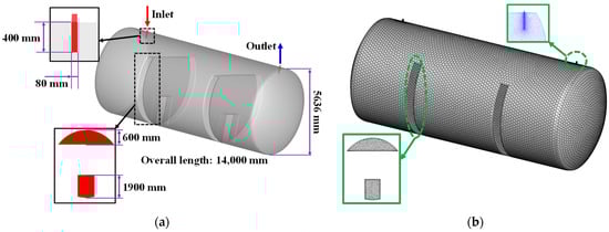
Figure 1.
(a) Physical model and (b) computational mesh structure of a diesel storage tank.
A velocity inlet boundary condition was applied at the tank inlet with a flow velocity of 1.105 m/s (equivalent to 20 m3/h). A pressure outlet boundary condition was applied at the tank outlet with ambient temperature and pressure maintained. Notably, adiabatic, no-slip and reflective boundary conditions were employed, which may omit factors such as temperature variation and material deterioration. When the conditioning oil concentration reaches the required level, a user-defined function monitors outlet velocity in real time and dynamically adjusts inlet velocity to achieve cyclic flow control.
Mesh generation for the geometric model was performed in Icem-CFD 2021 R2 software using unstructured, meshes composed mainly of hexahedral elements. To improve simulation accuracy, local mesh refinement was applied at the inlet and outlet regions, as shown in Figure 1b.
2.2. Numerical Methods
Ansys Fluent 2021 R2 software was employed to simulate the conditioning process within storage tanks. Due to the coexistence of diesel, conditioning oil, and air in the tank, and the immiscibility of air with the two oils, the volume of fluid (VOF) model was used to track the gas-liquid interface. A key advantage of this model is its compatibility with unstructured meshes [26]. Diesel and conditioning oil were defined as a mixture, and their interaction was described by the species transport model. The combination of VOF and species transport models has been widely applied in multiphase flow research [27,28,29,30].
The boundary condition at the inlet was assumed to be a pure conditioning oil VF of 1. When the conditioning oil concentration within the tank meets the required standard, cyclic flow of diesel and conditioning oil is implemented to ensure a uniform mixture distribution. During cyclic flow, a UDF monitors the outlet VF of diesel and conditioning oil in real time and dynamically adjusts the inlet composition. Specifically, during the simulation process, the average outlet velocity and conditioning oil mass fraction (calculated using the volume fractions and densities of diesel and conditioning oil) were written to an external file in real time. At the end of each time step, the ADJUST hook read the latest file data via static functions and verified that the mass fraction lay between 0 and 1, and that the velocity was non-negative. Once validated, the results were stored in global variables and applied as inlet boundary conditions by the PROFILE hook in the next time step. Furthermore, according to national standard GB19147-2016 [31], diesel at ambient temperature (20 °C) and atmospheric pressure was used as conditioning oil, as shown in Table 1. Experimental results indicated that degraded diesel exhibits a density decrease of 29.4 kg/m3 compared to fresh diesel. It should be noted that the tank is not fully filled with diesel. A certain amount of air exists at the inlet, outlet and upstream regions, which does not participate in the blending process.

Table 1.
Physical parameters of conditioning oil, degraded diesel and air.
In actual diesel storage tanks, degraded diesel predominantly accumulates around and beneath the baffles. Therefore, at the start of the simulation, the flow field must be initialized based on actual operating conditions by using the Patch function to define the diesel distribution. For the convenience of subsequent description, “degraded diesel” was abbreviated as “diesel”. Figure 2 shows the volume fraction contours of air and diesel inside the tank after patching. The SST k-ω two-equation model was employed to describe turbulent behavior inside the tank, incorporating low Reynolds number corrections, compressibility effects, and production limiters [32,33]. The main governing equations are detailed in the existing literature [34,35,36,37] and are not repeated. Additionally, the pressure-based coupled algorithm was used for pressure-velocity coupling. Gradients were computed using the least squares cell-based method. Momentum, turbulent kinetic energy and diffusion rates were discretized using a second-order upwind scheme.
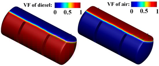
Figure 2.
Initial field of a diesel storage tank.
2.3. Simulation Validation
To ensure the reliability and accuracy of the numerical simulation, a grid independence study was performed using mesh sizes of 111,332, 224,973 and 338,576 elements. Figure 3 illustrates the average conditioning oil VF in the tank over time for the different mesh sizes. It can be observed that at the same time point, the coarse mesh produces a noticeably higher average VF compared to the two finer meshes. However, the difference between results obtained from the 224,973 element and 338,576 element meshes is less than 3%. Considering both computational cost and accuracy, the 224,973-element mesh was selected for the numerical simulation in this study.
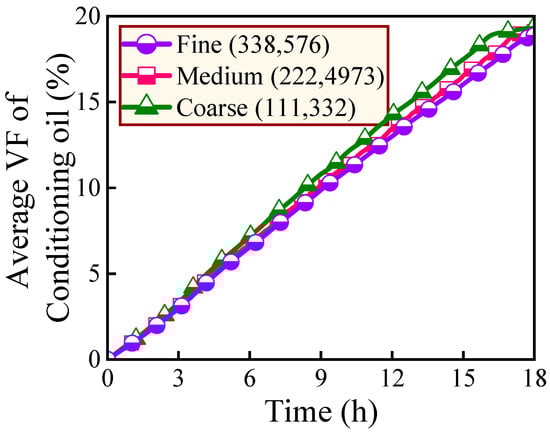
Figure 3.
Numerical simulation results for different number of meshes.
Based on the determined mesh size, this study further compares numerical simulation results with the actual time required for mixture homogenization under practical conditions, as shown in Figure 4. The experiments were performed under two conditions corresponding to conditioning oil volume fractions of 16% and 12%. First, the total mass of conditioning oil required for the two conditions was calculated based on the diesel volume in the tank and the measured densities of conditioning oil and diesel. Then the conditioning oil was injected through the inlet at a flow rate of 20 m3/h. After full injection of the conditioning oil, the mixture was circulated by the pump to cycle the composition and flow rate. The volume fraction of conditioning oil was measured hourly until the target value was reached. To ensure accuracy and reliability, three tests were performed under each condition, and the average value was reported. The error bars in Figure 4 represent the relative error range of the three trials. It should be noted that the oil blend was considered uniformly mixed within the tank when the VF of the conditioning oil at the outlet matched the average VF inside the tank during the simulation. Figure 4 demonstrates that the established numerical model can accurately predict the actual time required for the conditioning process. Therefore, subsequent studies are conducted based on this model.
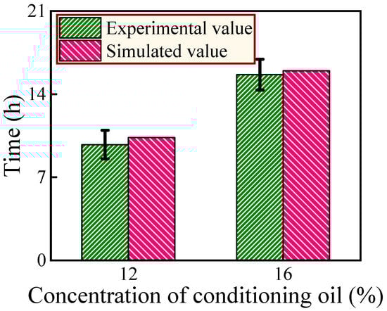
Figure 4.
Comparison between experimental measurements and numerical simulation results.
3. Results and Discussion
3.1. Effect of Different Baffle Structures on Diesel Conditioning Process
This study defines the conditioning requirement as met when the average VF of conditioning oil in the tank reaches 0.2. Figure 5 presents three different baffle designs with increasing flow area from left to right. For clarity, these three baffle structures are referred to as the single-flow, double-flow and triple-flow configurations.
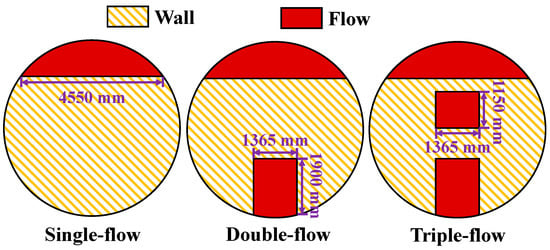
Figure 5.
Schematic diagrams of different baffle structures.
Figure 6 illustrates VF contours of conditioning oil inside the tank during mixing and cycling for three different baffle structures. To clearly present the distribution of conditioning oil, the contour range is limited from 0 to 0.3, and corresponding 3D views at selected times are shown. In the single-flow configuration, only a small amount of conditioning oil near the upstream inlet directly flows through the baffle region to the outlet. Most of the conditioning oil gradually accumulates in the inlet and central regions before entering the outlet area. Therefore, the conditioning oil concentration near the inlet is significantly higher than in other regions. When the average VF of conditioning oil in the tank reaches 0.2 and the species and velocity cycling begin, the conditioning oil concentration near the inlet rapidly decreases. However, the denser conditioning oil settles near the bottom. As cycling proceeds, the incoming lighter mixture progressively dilutes this layer from top to bottom, achieving uniformity.
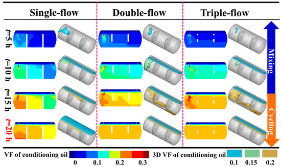
Figure 6.
VF contours of conditioning oil in the tank under different baffle structures.
In contrast, the double-flow and triple-flow configurations with bottom openings significantly reduce the accumulation of high-density conditioning oil. In the triple-flow configuration, after 15 h of mixing, the conditioning oil volume fraction is nearly uniform throughout the tank except near the bottom of the inlet and the top of the outlet. Once species and velocity cycling begin, both the double-flow and triple-flow configurations achieve uniform distribution of conditioning oil throughout the tank more quickly.
Figure 7 shows the time variation of VF at the inlet, outlet and as an average within the tank for three different baffle structures. The results indicate that in the single-flow configuration, conditioning oil begins to exit the outlet after approximately 1.5 h. When mixing time reaches approximately 16.6 h, the average VF in the tank reaches 0.2 and species and velocity cycling at the inlet and outlet begin. After approximately 7.4 h of cycling, conditioning oil achieves uniform distribution within the tank. The double-flow and triple-flow configurations feature bottom openings that facilitate rapid conditioning oil flow. Consequently, the outlet VF closely matches the tank average, and uniform distribution is achieved in a shorter time after cycling begins. However, a comparison between Figure 7b,c shows that, because of density differences between conditioning oil and diesel, the central opening in the triple-flow structure does not significantly accelerate mixing in the tank.
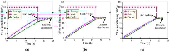
Figure 7.
Variation of conditioning oil VF at the inlet, outlet, and an average of the tank: (a) single-flow, (b) double-flow, and (c) triple-flow.
Figure 8 presents the mixing time, cycling time and relative wastage of conditioning oil. The relative wastage is calculated by integrating the outlet conditioning oil VF curve over the mixing time and normalizing it by the maximum integral value among the three baffle structures. Results show that as the baffle flow area increases, mixing time steadily increases while cycling time steadily decreases. Specifically, the mixing time of the single-flow structure is 96.86% of that of the double-flow structure and 88.68% of that of the triple-flow structure. Its cycling time is 162.78% of the double-flow value and 229.5% of the triple-flow value. Because the conditioning oil flow at the outlet of the single-flow structure is significantly lower than in the other two structures, the tank meets conditioning requirements more quickly, with minimal oil wastage. However, it also requires a substantially longer time to achieve a uniform distribution of conditioning oil during cycling.
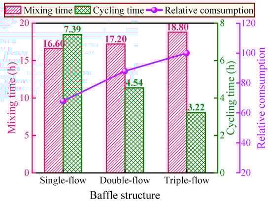
Figure 8.
Mixing time, cycling time, and relative consumption of conditioning oil under different baffle structures.
Moreover, the difference between the double-flow and triple-flow structures is relatively small. This indicates that because of the density difference between conditioning oil and diesel, the upstream openings of the baffles do not significantly promote rapid and uniform mixing. Therefore, to accelerate the mixing process, priority should be given to enlarging the flow area downstream of the baffles.
To further assess the mixing and cycling efficiencies under various baffle structures, a dimensionless metric η = 1 − t/tmax was introduced, where t is the mixing or cycling time for each design, and tmax is the maximum such time among the three structures. The results are summarized in Table 2. The single-flow structure with the narrowest channel has the longest residence time during the mixing phase. It achieves the highest dimensionless mixing efficiency and the lowest fuel consumption. However, this design also causes a significant reduction in circulation efficiency. In contrast, the triple-flow structure has the widest channel, making it difficult for the conditioning oil to accumulate in the tank, which leads to poor mixing efficiency. However, it most effectively enhances uniformity during the circulation phase and thus achieves the best overall performance. The double-flow structure achieves a good balance between mixing duration and circulation efficiency, making it the most practical option for implementation.
Table 2.
The mixing and cycling efficiencies under different baffle structures.
3.2. Effect of Different Baffle Numbers on Diesel Conditioning Process
Section 3.2 focuses on the double-flow configuration as a reference. Single, double and triple baffle arrangements were then installed to investigate their effect on mixture homogenization. Figure 9 shows VF contours of conditioning oil over time for different baffle numbers under the same conditions as in Figure 6. The results indicate that the fewer the baffles, the smaller the concentration difference of conditioning oil near the inlet and outlet. The three-dimensional views show that the single-baffle structure offers the least flow resistance to conditioning oil, allowing rapid diffusion upon entering the tank. Consequently, during the mixing period, regions of high conditioning oil concentration appear primarily near the inlet.
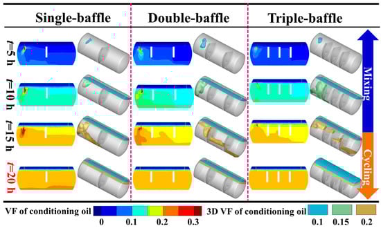
Figure 9.
VF contours of conditioning oil in the tank under different baffle numbers.
However, the single-baffle configuration has drawbacks during conditioning. It not only prolongs the mixing time of conditioning oil and diesel—thereby increasing oil wastage—but also leaves concentrations near the inlet and outlet elevated despite meeting the average requirement of the tank. Once species and velocity cycling begin, the high-concentration layer at the bottom of the tank remains difficult to dilute quickly, further extending the cycling time (t = 20 h in Figure 9). By contrast, the double-baffle and triple-baffle configurations achieve rapid uniform mixing of conditioning oil at earlier stages.
Figure 10 shows the variation in mixing time, cycling time and relative wastage of conditioning oil for different numbers of baffles. Results indicate that as the number of baffles increases, mixing time, cycling time and relative wastage all gradually decrease. This occurs because adding baffles reduces tank volume, lowering the required amount of conditioning oil, and increasing the conditioning oil concentration gradient between inlet and outlet, which cuts mixing-phase oil loss at the outlet and speeds attainment of the target concentration. Moreover, the larger concentration gradient between inlet and outlet enhances inlet dilution during cycling without significantly impeding conditioning oil flow, as shown in the single-baffle case in Figure 6. These findings demonstrate that increasing baffle number effectively accelerates conditioning oil mixing. However, Figure 10 also shows that the marginal benefit of adding a third baffle is significantly smaller than that of adding a second. Therefore, choosing an appropriate number of baffles is critical to achieving rapid conditioning.
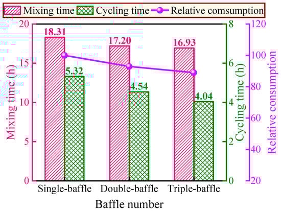
Figure 10.
Mixing time, cycling time and relative consumption of conditioning oil under different baffle numbers.
Table 3 presents the mixing and circulation efficiencies under different baffle numbers. It is evident that the triple-baffle achieves the highest efficiencies, while the single-baffle results in the lowest. This is because a greater number of baffles promotes the accumulation of conditioning oil near the inlet during the mixing process, which accelerates the achievement of the target mixing standard. In addition, the significant compositional difference between the conditioning oil at the inlet and outlet facilitates rapid dilution near the inlet during the circulation phase, which enhances circulation efficiency.
Table 3.
The mixing and cycling efficiencies under different baffle numbers.
4. Conclusions
This study uses actual diesel storage tank dimensions to establish a 3D model, coupling CFD and UDF to investigate the conditioning process under gas-liquid two-phase flow. The effects of different baffle structures and numbers on conditioning oil flow patterns, mixing time and cycling time are analyzed. The main conclusions are as follows:
- (1)
- Because conditioning oil is denser than diesel, high-concentration regions form near the inlet and central areas in the single-flow configuration. Openings at the bottom of the baffles in double-flow and triple-flow configurations significantly mitigate this phenomenon. As the baffle flow area increases, mixing time and relative wastage of conditioning oil gradually increase. However, species cycling time steadily decreases as baffle flow area increases.
- (2)
- Increasing the number of baffles reduces tank volume and enlarges the conditioning oil concentration gradient across the baffles, significantly shortening mixing time. Meanwhile, the larger concentration difference between inlet and outlet accelerates dilution of high-concentration conditioning oil at the inlet once species cycling begins, resulting in a marked reduction in cycling time. However, rates of decrease in mixing and cycling times diminish as baffle count increases. Therefore, choosing an appropriate number of baffles is critical for achieving rapid tempering.
Author Contributions
L.Z., C.W. and T.S.; writing—original draft preparation, software, methodology, B.Y.; validation, X.C.; formal analysis and resources, Q.M. and Y.Y.; data curation, H.Y. and X.M.; writing—original draft preparation, writing—review and editing and funding acquisition. All authors have read and agreed to the published version of the manuscript.
Funding
This research received no external funding.
Data Availability Statement
The original contributions presented in this study are included in this article; further inquiries can be directed to the corresponding author.
Conflicts of Interest
Authors Langqi Zhang, Chenping Wu and Yulong Yin were employed by the China Nuclear Power Operations Co., Ltd. Authors Tianyi Sun and Botao Yu were employed by the Hongyanhe Nuclear Power Co., Ltd. Authors Xiangnan Chu and Qi Ma were employed by the Yangjiang Nuclear Power Co., Ltd. The authors declare that they have no known competing financial interests or personal relationships that could have appeared to influence the work reported in this paper.
Abbreviations
The following abbreviations are used in this manuscript:
| 3D | Three-dimensional |
| CFD | Computational fluid dynamics |
| UDF | User-defined function |
| VF | Volume fraction |
| VOF | Volume of fluid |
References
- Sovacool, B.K.; Schmid, P.; Stirling, A.; Walter, G.; MacKerron, G. Differences in carbon emissions reduction between countries pursuing renewable electricity versus nuclear power. Nat. Energy 2020, 5, 928–935. [Google Scholar] [CrossRef]
- Papazis, S.A. Nuclear–Thermal Power Generation: Multicriteria Optimization of the Economic Sustainability. Sustainability 2025, 17, 4781. [Google Scholar] [CrossRef]
- Steinhauser, G.; Brandl, A.; Johnson, T.E. Comparison of the Chernobyl and Fukushima nuclear accidents: A review of the environmental impacts. Sci. Total Environ. 2014, 470, 800–817. [Google Scholar] [CrossRef]
- Onda, Y.; Taniguchi, K.; Yoshimura, K.; Kato, H.; Takahashi, J.; Wakiyama, Y.; Coppin, F.; Smith, H. Radionuclides from the Fukushima Daiichi nuclear power plant in terrestrial systems. Nat. Rev. Earth Environ. 2020, 1, 644–660. [Google Scholar] [CrossRef]
- Ohba, T.; Tanigawa, K.; Liutsko, L. Evacuation after a nuclear accident: Critical reviews of past nuclear accidents and proposal for future planning. Environ. Int. 2021, 148, 106379. [Google Scholar] [CrossRef]
- Nagatani, K.; Kiribayashi, S.; Okada, Y.; Otake, K.; Yoshida, K.; Tadokoro, S.; Nishimura, T.; Yoshida, T.; Koyanagi, E.; Fukushima, M. Emergency response to the nuclear accident at the Fukushima Daiichi Nuclear Power Plants using mobile rescue robots. J. Field Robot. 2013, 30, 44–63. [Google Scholar] [CrossRef]
- Marqusee, J.; Don, D.J., II. Reliability of emergency and standby diesel generators: Impact on energy resiliency solutions. Appl. Energy 2020, 268, 114918. [Google Scholar] [CrossRef]
- Jeong, Y.-S.; Baek, E.-R.; Jeon, B.-G.; Chang, S.-J.; Park, D.-U. Seismic performance of emergency diesel generator for high frequency motions. Nucl. Eng. Technol. 2019, 51, 1470–1476. [Google Scholar] [CrossRef]
- Zhang, L.; He, Y.; Zhou, Y.; Jiang, G.; Chu, X.; Ma, Q.; Liu, F.; Ye, H. A Comprehensive Optimization Framework for Diesel Filtration in Nuclear Emergency Systems: Integrating Genetic Algorithms, State-Space Networks, and Computational Fluid Dynamics. Processes 2025, 13, 648. [Google Scholar] [CrossRef]
- Kumar, N. Oxidative stability of biodiesel: Causes, effects and prevention. Fuel 2017, 190, 328–350. [Google Scholar] [CrossRef]
- Longanesi, L.; Pereira, A.P.; Johnston, N.; Chuck, C.J. Oxidative stability of biodiesel: Recent insights. Biofuel. Bioprod. Bior. 2022, 16, 265–289. [Google Scholar] [CrossRef]
- Hosseinzadeh-Bandbafha, H.; Kumar, D.; Singh, B.; Shahbeig, H.; Lam, S.S.; Aghbashlo, M.; Tabatabaei, M. Biodiesel antioxidants and their impact on the behavior of diesel engines: A comprehensive review. Fuel Process. Technol. 2022, 232, 107264. [Google Scholar] [CrossRef]
- Pullen, J.; Saeed, K. An overview of biodiesel oxidation stability. Renew. Sustain. Energ. Rev. 2012, 16, 5924–5950. [Google Scholar] [CrossRef]
- Bello, U.; Adamu, H.; Samsuri, S.; Ibrahim, H.; Qamar, M. Improving biodiesel oxidative stability using antioxidants: An insight into the research trends and future prospects from a bibliometric approach. Results Eng. 2025, 26, 105185. [Google Scholar] [CrossRef]
- Karavalakis, G.; Stournas, S. Impact of antioxidant additives on the oxidation stability of diesel/biodiesel blends. Energy Fuels 2010, 24, 3682–3686. [Google Scholar] [CrossRef]
- Malik, M.A.I.; Kalam, M.; Abbas, M.M.; Silitonga, A.S.; Ikram, A. Recent advancements, applications, and technical challenges in fuel additives-assisted engine operations. Energy Conv. Manag. 2024, 313, 118643. [Google Scholar] [CrossRef]
- Rodrigues, J.S.; do Valle, C.P.; Uchoa, A.F.J.; Ramos, D.M.; da Ponte, F.A.F.; Rios, M.A.d.S.; de Queiroz Malveira, J.; Pontes Silva Ricardo, N.M. Comparative study of synthetic and natural antioxidants on the oxidative stability of biodiesel from Tilapia oil. Renew. Energy 2020, 156, 1100–1106. [Google Scholar] [CrossRef]
- Elkelawy, M.; Aly Farag, M.; Seleem, H.E. Enhancing Diesel Engine Power Plant Efficiency and Cutting Emissions with Commercial Fuel Additives in Generator Systems. Pharos Eng. Sci. J. 2025, 2, 37–46. [Google Scholar] [CrossRef]
- Muhyi, A.; Silitonga, D.; Alfian, D.C.; Supriyadi, D.; Prahmana, R. Performance Characterization of Diesel Engine Generator Set with the Addition of Clove Oil as Bio-Additives for Diesel Fuel; IOP Conference Series: Earth and Environmental Science; IOP Publishing: Bristol, UK, 2019; p. 012009. [Google Scholar] [CrossRef]
- Işık, M.Z.; Bayındır, H.; İscan, B.; Aydın, H. The effect of n-butanol additive on low load combustion, performance and emissions of biodiesel-diesel blend in a heavy duty diesel power generator. J. Energy Inst. 2017, 90, 174–184. [Google Scholar] [CrossRef]
- Nagappan, M.; Devaraj, A.; Babu, J.M.; Vibhav Saxena, N.; Prakash, O.; Kumar, P.; Sharma, A. Impact of additives on Combustion, performance and exhaust emission of biodiesel fueled direct injection diesel engine. Mater. Today Proc. 2022, 62, 2326–2331. [Google Scholar] [CrossRef]
- Chen, B.-Y.; Chen, Y.-S. Heat transfer analysis for the temporary spent fuel storage of the Chinshan nuclear plant. Nucl. Eng. Des. 2024, 428, 113535. [Google Scholar] [CrossRef]
- Bae, J.-W.; Noh, B.-S.; Lee, J.-W.; Choe, S.-J.; Park, K.-H.; Kim, J.-D.; Choi, J.-H. Quantitative Analysis of Explosion Characteristics Based on Ignition Location in an Ammonia Fuel Preparation Room Using CFD Simulation. Appl. Sci. 2025, 15, 6554. [Google Scholar] [CrossRef]
- Calabrese, M.; Portarapillo, M.; Di Nardo, A.; Venezia, V.; Turco, M.; Luciani, G.; Di Benedetto, A. Hydrogen safety challenges: A comprehensive review on production, storage, transport, utilization, and CFD-based consequence and risk assessment. Energies 2024, 17, 1350. [Google Scholar] [CrossRef]
- Zhu, W.; Meng, X.; Zhang, M.; Zhang, X.; Cui, Z.; Tian, J.; Long, W.; Bi, M. Synergistic effects of CO2 dilution and H2 addition on the laminar combustion characteristics of NH3/CH4 blends at high temperature and pressure. Energy 2025, 320, 135267. [Google Scholar] [CrossRef]
- Jiang, S.; Zhao, Y.; Zhao, X.; Chen, C.; Tu, W.; Chi, Y.; Wang, J. Dense Phase Mixing in a Solid-Liquid Stirred Tank by Computational Fluid Dynamics Simulation. Processes 2025, 13, 1876. [Google Scholar] [CrossRef]
- Feng, P.; Tan, L.; Cao, Y.; Chen, D. Numerical investigations of two-phase flow coupled with species transport in proton exchange membrane fuel cells. Energy 2023, 278, 127918. [Google Scholar] [CrossRef]
- Mohd Laziz, A.; Chuah, C.Y.; Denecke, J.; Bilad, M.R.; Ku Shaari, K.Z. Investigation of Mass-Transfer Performance for Biodiesel Reaction in Microchannel Reactor using Volume-of-Fluid with Species-Transport Model. Sustainability 2023, 15, 6148. [Google Scholar] [CrossRef]
- Al-rifai, S.; Cao, Y. Multiphase modeling of heat and mass transfer inside transport membrane condenser (TMC) tube bundle. Int. J. Heat Mass Transf. 2023, 214, 124429. [Google Scholar] [CrossRef]
- Satish, R.; B. T, R.; Raju, S.S.K.; Al Mukahal, F.H.H.; Souayeh, B.; Varma, S.V.K. Radiated Free Convection of Dissipative and Chemically Reacting Flow Suspension of Ternary Nanoparticles. Processes 2025, 13, 1030. [Google Scholar] [CrossRef]
- GB19147-2016; Standardization Administration: Automobile Diesel Fuels. General Administration of Quality Supervision, Inspection and Quarantine of the People’s Republic of China: Beijing, China, 2016. Available online: https://std.samr.gov.cn/ (accessed on 15 March 2025).
- Song, Z.; Chen, Y.; Yu, T.; Wang, X.; Cao, H.; Li, Z.; Lang, X.; Xu, S.; Lu, S.; Jiang, C. Influence of the Trailing Edge Shape of Impeller Blades on Centrifugal Pumps with Unsteady Characteristics. Processes 2024, 12, 508. [Google Scholar] [CrossRef]
- Soloveva, O.V.; Solovev, S.A.; Shakurova, R.Z. Numerical Study of the Thermal and Hydraulic Characteristics of Plate-Fin Heat Sinks. Processes 2024, 12, 744. [Google Scholar] [CrossRef]
- Zhu, W.; Wang, Y.; Wang, J. Flow field of a rotating detonation engine fueled by carbon. Phys. Fluids 2022, 34, 073311. [Google Scholar] [CrossRef]
- Wang, J.; Wang, M.; Yu, X.; Zong, R.; Lu, S. Experimental and numerical study of the fire behavior of a tank with oil leaking and burning. Process Saf. Environ. Protect. 2022, 159, 1203–1214. [Google Scholar] [CrossRef]
- Rybak, I.; Gray, W.; Miller, C. Modeling two-fluid-phase flow and species transport in porous media. J. Hydrol. 2015, 521, 565–581. [Google Scholar] [CrossRef]
- Bothe, D.; Fleckenstein, S. A volume-of-fluid-based method for mass transfer processes at fluid particles. Chem. Eng. Sci. 2013, 101, 283–302. [Google Scholar] [CrossRef]
Disclaimer/Publisher’s Note: The statements, opinions and data contained in all publications are solely those of the individual author(s) and contributor(s) and not of MDPI and/or the editor(s). MDPI and/or the editor(s) disclaim responsibility for any injury to people or property resulting from any ideas, methods, instructions or products referred to in the content. |
© 2025 by the authors. Licensee MDPI, Basel, Switzerland. This article is an open access article distributed under the terms and conditions of the Creative Commons Attribution (CC BY) license (https://creativecommons.org/licenses/by/4.0/).