Abstract
To solve the problem of traditional engineering drilling rig propulsion systems being difficult to adapt to complex working conditions due to their bulky structure and poor load adaptability, this study proposes a new type of mechanical hydraulic composite electro-hydraulic proportional propulsion system. The system innovatively adopts a composite design of parallel hydraulic cylinders and movable pulley groups in mechanical structure, aiming to achieve system lightweighting through displacement multiplication effect. In terms of control strategy, a fuzzy adaptive PID controller based on position feedback was designed to improve the dynamic tracking performance and robustness of the system under nonlinear time-varying loads. The study established a multi physics domain mathematical model of the system and conducted joint simulation using AMESim and MATLAB/Simulink to deeply verify the overall performance of the proposed scheme. The simulation results show that the mechanical structure can stably achieve a 2:1 displacement multiplication effect, providing a feasible path for shortening the system size. Compared with traditional PID control, the proposed fuzzy adaptive PID control strategy significantly improves the positioning accuracy of the system. The maximum tracking errors of the master and slave hydraulic cylinders are reduced from 6.3 mm and 10.4 mm to 2.3 mm and 5.6 mm, respectively, and the accuracy is improved by 63.49% and 46.15%, providing theoretical support and technical reference for the design of engineering drilling rig propulsion control systems.
1. Introduction
With the advancement of major engineering projects, such as the Sichuan–Tibet Railway power transmission project, hydropower development in Southwest China, and other critical infrastructure, there is a pressing need for engineering drilling rigs to significantly improve the quality and progress of construction, particularly in foundation pit excavation [1]. At present, to adapt to the complex construction conditions in mountainous regions, researchers are improving the structure and control methods of drilling rigs based on existing technologies. However, conventional manual control methods exhibit inherent delays and errors in the judgment of operational conditions. Moreover, these control modes, which rely heavily on operator experience, are incapable of adapting the drilling power output in response to fluctuating loads [2,3]. Therefore, achieving equipment lightweighting through new system and structural designs, while utilizing advanced control strategies for precise control of the drilling trajectory, has become a key research focus in the intelligent development of engineering drilling rigs.
To address the challenges associated with the transportation of drilling rigs and the problem of load-following control in drilling systems, researchers have conducted the following studies.
In terms of transportation and structural design, Chen Weiyu et al. [4] proposed a miniaturized steel pipe pile drilling rig for mountainous terrains to accelerate the mechanization of ultra-high voltage (UHV) transmission line construction. Although it improved the project’s progress, the rig’s propulsion device was 4 m long and its total weight reached 17 tons, making the equipment excessively bulky. Yao Zhentong et al. [5] applied a modular design to existing equipment to address transportation difficulties; however, with a 4 m propulsion system, the rig remained cumbersome. Li Lianzhong et al. [6], tackling issues of scattered components and the extensive labor required for disassembly and transport, utilized integrated and modular design concepts to develop a rapid-movement and quick-installation rig for oil and water well drilling and workover operations. To improve the efficiency of all-hydraulic rotary blasthole drills, Han Jiawei [7] designed separate traveling and auxiliary hydraulic systems using open-loop and closed-loop configurations, respectively, which resulted in a complex system with high maintenance costs. To overcome transportation challenges in high-altitude regions, Wang et al. [8] designed a tool cart system based on modular drilling rig assembly, which provides an innovative solution to the transportation of large equipment and installation of steel cages in mountainous construction of ultra-high voltage engineering through a modular design of walking chassis, mechanical gripper, and boom. Liu Zhong et al. [9] invented a crawler-type traveling apparatus, enhancing the mobility of drilling rigs in complex mountainous terrains. Wang et al. [10] designed a ZMK5530TZJ100 vehicle-mounted drilling rig, which adopts a highly integrated design, integrates the drilling rig functions into the vehicle chassis, and is equipped with a hydraulic and electro-hydraulic dual-mode control system. It successfully completed the construction of a 1675 m horizontal directional well in the Sihe mining area of Shanxi Province.
In response to the problem of difficulty in matching the control parameters of the drilling system with time-varying loads, researchers have conducted the following research: Chen et al. [11] investigated an energy-saving strategy for a hybrid drilling rig system using a logic threshold method. Their simulations confirmed that the machine-hydraulic hybrid power system was more energy-efficient than conventional hydraulic transmission systems, achieving an efficiency improvement of over 15.9%. Li et al. [12] proposed a master–slave adjustment method based on a PID control strategy to address the displacement deviation problem of the dual propulsion cylinder of the power head of the engineering hydraulic drilling rig under external disturbances. Through AMESim Simulink joint simulation verification, the system achieved stable control within 0.17 s, with a synchronization control error of 0.0005 m between cylinder 1 and the expected value, and a stability error of 0.0006 m between cylinder 2 and cylinder 1, meeting the requirements of the engineering drilling rig for the synchronization accuracy of the power head propulsion system. Liang et al. [13] employed an adaptive PID control strategy to regulate engine output power under varying operational conditions to reduce fuel consumption. Jia Cunde et al. [14] proposed a composite anti-interference strategy based on a load disturbance observer and LQR control. By real-time estimation of load torque and feedforward compensation of valve core displacement, the peak speed fluctuation of the rotary drilling rig was reduced by 84.7%, the peak acceleration fluctuation was reduced by 81.3%, and the mast oscillation was reduced by 52.5%. Xu Xiang et al. [15] proposed a staged engine speed control strategy based on drill pipe drilling speed, which improved the overall work efficiency by 15% and reduced the overall fuel consumption by 5.74%. Ji et al. [16] proposed a nonlinear adaptive backstepping control method based on a disturbance observer, which considers parameter uncertainty and external disturbances as system composite disturbances. Compared with traditional PID control, the position tracking error of the drilling rig deviation control system is reduced by 38%. Zhang et al. [17] compared and analyzed the adaptability of traditional PID and feedback linearization sliding mode variable structure control algorithms in the automatic drilling of vehicle-mounted drilling rigs and found that the latter had more ideal response speed, control accuracy, and robustness, and reduced the system tracking error to 30% of traditional PID control. Zhang Zhen et al. [18] proposed a global terminal sliding mode control method based on an adaptive extended state observer. By integrating tracking error and estimation error to design a new observer, the tracking error of the drilling rig’s speed system under step disturbance is reduced to 0.0008 r/min, which is 99.8% higher than traditional methods. Wu et al. [19] proposed an adaptive pump pressure control strategy based on a proportional relief valve and a variable gain PID algorithm, which adjusts the pump pressure in real time to compensate for the pipeline pressure loss caused by changes in hydraulic oil viscosity. This reduces the energy consumption of the deep-sea valve-controlled hydraulic cylinder system by 36.5–47% when operating at a depth of 11 km, while maintaining a position tracking error of less than 1 mm, achieving the unity of energy saving and precise control of hydraulic systems in extreme deep-sea environments. He et al. [20] proposed a collaborative control strategy based on pressure position conversion gain for the high-speed, large-inertia, high-frequency response, and multi degree of freedom characteristics of the fully hydraulic straightening electromechanical servo system. The strategy was verified through AMESim simulation to shorten the system response time to 0.1 s, and the maximum position deviation during four cylinder synchronous motion was controlled within 0.15 mm.
Conventional drilling rig propulsion systems are constrained by two primary design bottlenecks. First, from a structural standpoint, the propulsion apparatus typically measures 4 m in length, resulting in a bulky and massive system. Although modular designs have mitigated transportation challenges, they have not fundamentally reduced the overall system weight, thereby limiting deployment in complex terrains such as mountainous regions. Second, a dichotomy exists in control strategies: advanced methods like terminal sliding mode and active disturbance rejection control, while theoretically powerful, exhibit high dependency on precise mathematical models and possess complex structures, which compromises their stability and feasibility for practical engineering implementation [21]. Conversely, traditional PID control, despite its simplicity, struggles to adapt to varying loads due to its fixed gains.
To systematically address these challenges, this study proposes a position-feedback-based control strategy for a mechano-hydraulic composite propulsion system. The core of this strategy is the integration of fuzzy logic theory with a conventional PID controller to form a fuzzy adaptive PID controller. This controller utilizes the real-time position error (e) and its rate of change (ec) as inputs to perform online self-tuning of the PID parameters via fuzzy logic. This design aims to overcome the inherent limitations of fixed-gain PID controllers while avoiding complex model dependency, thereby effectively enhancing the control precision, operational stability, and dynamic response of the mechano-hydraulic composite system.
2. Working Principle of Propulsion System
In the context of high-altitude operations, the efficient and stable performance of drilling rigs is critical to the success of drilling tasks. The hydraulic control system, a core component, integrates key elements such as an electro-hydraulic proportional valve, a hydraulic pump, and a relief valve. These components work in synergy to ensure robust power transmission and precise control for the drilling rig, an example of which is depicted in its operational environment in Figure 1.
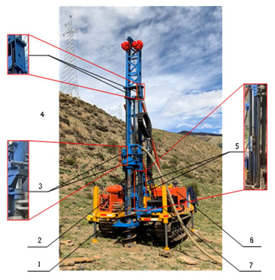
Figure 1.
Drilling operations of drilling rigs in high-altitude areas. 1—power head; 2—hydraulic control system device; 3—hydraulic cylinder; 4—fixed pulley; 5—movable pulley; 6—engine; 7—hydraulic pump.
The mechano-hydraulic composite propulsion system, a primary execution unit of the rig, is fundamentally a valve-controlled cylinder system. This system is composed of hydraulic cylinders, an electro-hydraulic proportional valve, a signal input module, displacement sensors, a power head, a hydraulic pump, a pulley system of movable and fixed pulleys, and the external load. The hydraulic cylinder acts as the primary actuator, precisely regulated by the electro-hydraulic proportional valve to achieve accurate control over the power head’s motion. A displacement sensor provides real-time position feedback, establishing a closed-loop control architecture to ensure the stability and accuracy of the propulsion process. The pulley system optimizes the power transmission efficiency by modifying the direction and magnitude of the applied force. The working principle of this mechano-hydraulic propulsion system is schematically illustrated in Figure 2, which delineates the interconnections among components and the energy transfer pathways, providing an intuitive basis for understanding the system’s operational mechanism and for subsequent design optimization.
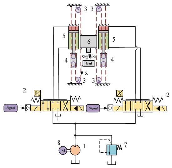
Figure 2.
Principle of hydraulic series propulsion system. 1—hydraulic pump; 2—electro-hydraulic proportional valve; 3—fixed pulley; 4—moving pulley system; 5—hydraulic cylinder; 6—power head; 7—overflow valve; 8—motor.
To address the design bottlenecks concerning the length and mass of conventional mast-type propulsion systems, this study proposes a novel mechano-hydraulic composite propulsion system featuring parallel hydraulic cylinders. The core of this system’s architecture lies in the coupling of two parallel hydraulic cylinders with a mechanical transmission mechanism comprising both movable and fixed pulleys. Powered by a hydraulic pump, the system utilizes electric signals to precisely regulate an electro-hydraulic proportional valve, which in turn governs the dynamic output of the hydraulic cylinders. The key innovation resides in its kinematic design, whereby linking the movable pulleys with the hydraulic cylinder piston rods constructs a displacement multiplication mechanism. This mechanism leverages the physical principles of the pulley system to establish a deterministic 2:1 motion amplification ratio, wherein the final propulsion displacement of the power head is double the stroke of the hydraulic cylinder. This design enables the required hydraulic cylinder stroke to be halved while satisfying the same operational travel requirements. Consequently, this directly and significantly reduces the structural length and mass of the entire propulsion mast, thereby enhancing the system’s compactness and operational stability.
3. Establishment of Theoretical Models for Propulsion Systems
3.1. Theoretical Model of Electro-Hydraulic Proportional Valve
The electro-hydraulic proportional valve is primarily composed of an adjusting screw, an adjusting spring, an armature, a solenoid coil, a push rod, a solenoid end cover, a spool, a return spring, and the valve body [22,23]. The operating principle of the electro-hydraulic proportional valve is illustrated in Figure 3.
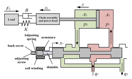
Figure 3.
Principle of operation of electro-hydraulic proportional valves.
During the operation of the electro-hydraulic proportional valve, its spool is subjected to several forces, including the electromagnetic force, forces from hydraulic pressure, and spring force. A free-body diagram of the forces acting on the spool is presented in Figure 4. Based on these interactions, the force balance equation for the main spool can be established [24,25]:
where Fm is the electromagnetic force, Fflow is the steady-state flow force acting on the main spool, mv is the mass of the main spool, cv is the viscous damping coefficient of the main spool, xv is the displacement of the main spool, x0 is the initial spring compression at the spool’s starting position, kv is the spring stiffness of the main spool, N is the number of coil turns, μ0 is the magnetic permeability of air, A is the cross-sectional area of the air gap, i is the coil current, δ is the length of the air gap, Ps is the load pressure at the end face of the main spool, Av is the cross-sectional area of the main spool’s end face, PL is the hydraulic pressure on the left side of the main spool, and PR is the hydraulic pressure on the right side of the main spool.
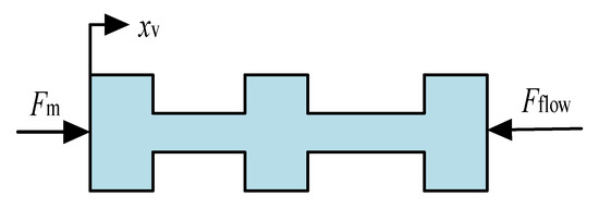
Figure 4.
Spool force diagram electro-hydraulic proportional valve working principle.
Flow equation for the main valve spool:
where Kq is the flow gain of the electro-hydraulic proportional valve, Ke is the flow-pressure coefficient of the proportional valve, P1 is the pressure in the rodless chamber of the hydraulic cylinder, P2 is the pressure in the rod-side chamber of the hydraulic cylinder, and Pz is the load pressure of the hydraulic cylinder.
3.2. Theoretical Model of Hydraulic Cylinder
The kinematics equation of the hydraulic cylinder is given by Figure 2:
where Ae is the effective area of the hydraulic cylinder, FhL is the total external force acting on the piston rod, Mh is the mass of the piston rod and its assembly, Bh is the viscous damping coefficient of the hydraulic cylinder, Kh is the spring stiffness of the hydraulic fluid, X is the displacement of the hydraulic cylinder, A1 is the effective area of the cylinder’s rodless chamber, and A2 is the effective area of the cylinder’s rod-side chamber.
The flow equation for a hydraulic cylinder is
where Ct is the equivalent leakage coefficient of the hydraulic cylinder, Vt is the equivalent total volume of the hydraulic cylinder, and βe is the effective bulk modulus of the hydraulic fluid.
3.3. Theoretical Model of a Pulley Block
As shown in Figure 2, the movable pulley of the block and tackle system is mounted on the piston rod of the hydraulic cylinder. The resulting equation of motion for the power head is as follows:
where FM is the propulsion force of the power head, FL/2 is the resultant force acting on a single hydraulic cylinder, comprising the drilling load and self-weight, M1 is the mass of the power head, B is the viscous damping coefficient of the load, K is the spring stiffness of the load, and X1 is the displacement of the power head.
Associative Equations (10)–(12) can be obtained:
3.4. Displacement Transfer Function of the Propulsion System
A Lagrangian transformation of Equations (5), (9), and (13) yields
The first step of derivation is to eliminate the intermediate variable qL(s), combine the Laplace-transformed Equations (5) and (9) in Equation (14), and merge the terms containing pL(s) to the right side of the equation to obtain Equation (15):
The next step is to eliminate the load pressure PZ(s). From the formula after the pull transformation of Equation (13) in Equation (14), the relationship between PZ(s) and the output displacement X(s) and the disturbing force FL(s) can be directly solved:
Substituting PZ(s) represented by Equation (16) into Equation (15) to eliminate PZ(s), Equation (17) containing only input XV(s), FL(s) and output X(s) is obtained:
Moving all the terms containing X(s) to the right of the equation and the other terms to the left in order to obtain the standard transfer function form, we divide the entire equation by Ae, as shown in Equation (18):
Let (Kt = ke + Ct) be the total flow pressure coefficient, and sort out the coefficients of X(s) according to the power of S; that is, the characteristic polynomial of the system simplifies the above into Formula (19):
From Equation (17), we can solve the output displacement X(s). It consists of two parts: one part is generated by the control input Xv(s), and the other part is generated by the disturbance force FL(s). According to the superposition principle of the linear system, it can be written as Equation (20):
where Gvx(s) is the transfer function of displacement to control input, GFx(s) is the transfer function of displacement to load disturbance, ωh is the hydraulic natural frequency, and ζh is the damping ratio.
From Equations (15)–(20), the transfer function of the output displacement x (s) of the hydraulic cylinder can be calculated as Equation (21):
Combining Equations (7) and (10), it can be seen that the propulsive displacement of the power head is two times the propulsive displacement of the hydraulic cylinder, and the individual hydraulic cylinder load is equal to the sum of the power head load. From Equation (21), it can be seen that the output displacement of the hydraulic cylinder and power head is positively correlated with the valve opening xv of the electro-hydraulic proportional valve.
4. Modeling and Analysis of Propulsion System Control Systems
4.1. Principles of Displacement Feedback Control for Propulsion Systems
The propulsion control system is composed of a main circuit and a feedback control loop. The main circuit encompasses the hydraulic transmission unit, the block and tackle system, and the power head assembly. The feedback loop primarily consists of the displacement sensor and the controller. A schematic of the control system is presented in Figure 5. Under stable load conditions, the control process begins with a desired displacement trajectory, Ux, as the input reference. This signal is processed by the controller, which generates an output current, I1. This current modulates the spool opening, xv1, of the electro-hydraulic proportional valve, which in turn controls the output displacement, Xh1, of the No. 1 hydraulic cylinder. The actual displacement, Xh1, is measured by displacement sensor 1 and fed back to the PID controller. The controller continuously calculates the displacement error, Ue1, between the desired trajectory and the measured position. Based on this error, the PID controller adjusts its output current, I1, to finely regulate the valve opening, xv1. This closed-loop action ensures that the cylinder’s actual displacement accurately tracks the desired trajectory. In this master–slave control scheme, the No. 2 hydraulic cylinder (the slave) uses the position of the No. 1 cylinder (the master) as its reference signal, Ur1. This reference is compared with the actual measured position of the No. 2 cylinder, Ur2, which is acquired by its respective displacement sensor. The resulting synchronization error, Ue2, is then processed by a conventional PID controller. The PID controller continuously adjusts its output current, I2, based on this synchronization error. This current modulates the spool displacement, xv2, of the second electro-hydraulic proportional valve, thereby controlling the motion of the No. 2 cylinder. This closed-loop configuration forces the displacement of the slave cylinder, Xh2, to precisely track the displacement of the master cylinder, Xh1 The ultimate objective is to drive the synchronization error (Ue2) to be asymptotically close to zero, or to have it fluctuate within a minimal tolerance band around zero. This ensures that the output displacements, Xh1 and Xh2, are nearly identical. By achieving this synchronization, both cylinders collectively follow the overall ideal displacement trajectory, which enables the drilling rig’s power head to effectively adapt to varying load conditions.
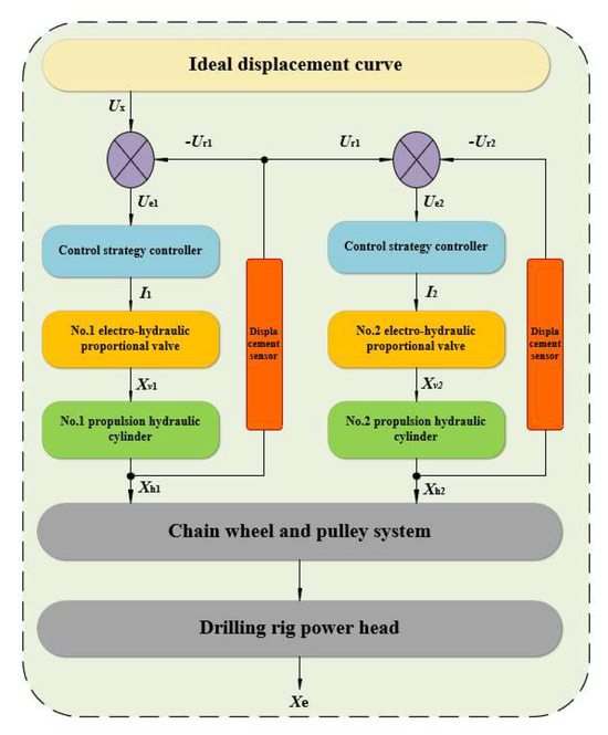
Figure 5.
Propulsion system control principles.
4.2. Advancing Control System Modeling
To investigate the mechano-hydraulic composite propulsion system, a co-simulation approach was employed, utilizing specialized modeling tools for distinct subsystems. The main hydraulic circuit was modeled using 2021 AMESim software, whereas the control system was developed within the MATLAB/Simulink environment. Co-simulation between these two platforms was achieved by generating an S-function from the AMESim model for integration into Simulink. To enhance the system’s adaptability to load variations and improve its dynamic response, both the AMESim model of the main circuit and the MATLAB/Simulink model of the control system were subject to design optimization. The corresponding simulation models are illustrated in Figure 6, Figure 7 and Figure 8.
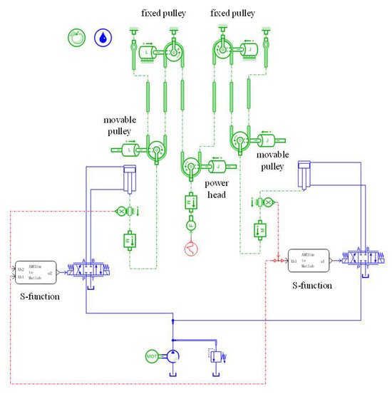
Figure 6.
Simulation model of the main circuit section in AMESim.
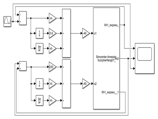
Figure 7.
MATLAB/Simulink simulation model of conventional PID control system.
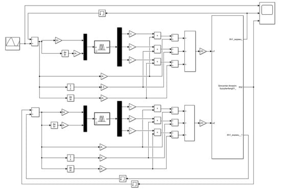
Figure 8.
MATLAB/Simulink simulation model for fuzzy adaptive PID control system.
4.3. Controller Design
In this study, both a conventional Proportional–Integral–Derivative (PID) control and a fuzzy adaptive PID control strategy were employed to simulate the propulsion system’s tracking of an ideal displacement trajectory. Based on a comprehensive consideration of the dynamic characteristics and steady-state performance of the system, and through in-depth analysis of traditional PID control theory, combined with relevant engineering practice cases and theoretical derivation, the optimal initial PID parameters have been determined [26], with initial values of: Kp1 = 145.65; Ki1 = 6.5; Kd1 = 0.015; Kp2 = 205.5; Ki2 = 0.35; Kd2 = 0.15. To overcome the performance limitations of conventional PID controllers, which stem from their fixed gains, a fuzzy logic-based enhancement was introduced. This approach leverages fuzzy control principles to perform online tuning of the proportional (Kp), integral (Ki), and derivative (Kd) gains based on the real-time position error (e) and its rate of change (ec), thereby satisfying the dynamic control parameter requirements of the hydraulic cylinder’s position servo process. The fundamental principle of the designed fuzzy adaptive PID controller is illustrated in Figure 9.
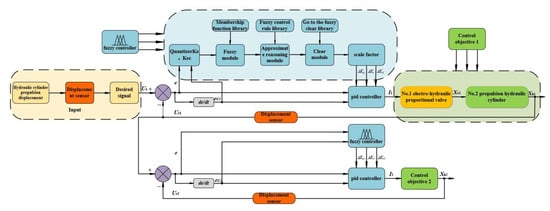
Figure 9.
Principle of fuzzy adaptive PID control.
The system tracks an ideal displacement curve (Ux), with the tracking error provided by a displacement sensor. Within the fuzzy control framework, this error (e) and its rate of change (ec) are first fuzzified. Subsequently, a rule-based inference engine determines the necessary adjustments, which are then defuzzified to yield precise tuning values for the PID parameters. This mechanism facilitates the real-time, dynamic adjustment of the PID gains, enabling the system to better adapt to load variations and ultimately enhancing its control accuracy and stability.
4.3.1. Design of Fuzzy PID Controller
In the adaptive PID control framework proposed in this article, the core is a fuzzy logic controller (FLC), which takes the system error (e) and its rate of change (ec) as input variables [27]. The output of the controller is the incremental adjustment parameters provided for the traditional PID loop, namely (∆Kp, ∆Ki, ∆Kd). The specific design of the controller is as follows:
- (1)
- For the first fuzzy controller, the input variables are the error e1 (where e1 = Ux − Ur1) and its rate of change ec1 (where ec1 = de1/dt). The universe of discourse for both e1 and ec1 is quantified and mapped to the normalized interval [−6, −4, −2, 0, 2, 4, 6]. This interval is partitioned into seven linguistic fuzzy subsets: {Negative Big (NB), Negative Medium (NM), Negative Small (NS), Zero (Z), Positive Small (PS), Positive Medium (PM), and Positive Big (PB)}. Correspondingly, the universes of discourse for the output variables, ΔKp1, ΔKi1, and ΔKd1, are also set to the interval [−6, −4, −2, 0, 2, 4, 6], which is divided into four fuzzy subsets: {Zero (Z), Positive Small (PS), Positive Medium (PM), and Positive Big (PB)}.
- (2)
- The second fuzzy controller selects input variables e2 and ec2 as fuzzy variables, where e2 = Ur2 − Ur2, ec2 = de2/dt. Other settings are consistent with the first fuzzy controller.
A Mamdani-type fuzzy inference system was selected for this study, owing to its intuitive rule-base structure and its capacity for effectively encoding expert knowledge. Furthermore, considering computational efficiency and simplicity of implementation, the membership functions for all input variables were defined using a hybrid Gaussian–triangular function (gaussmf + trimf), while the output variable membership functions utilized a more sensitive triangular function (trimf), as depicted in Figure 10.
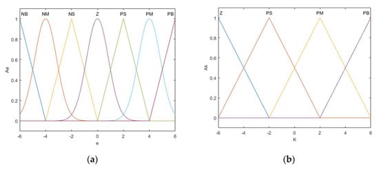
Figure 10.
(a) Input variable membership function; (b) output variable membership function.
Based on this framework, a fuzzy rule base (Table 1) was constructed.

Table 1.
Fuzzy rule table.
Drawing upon core engineering principles of PID gain tuning and extensive empirical knowledge, this rule base defines the nonlinear mapping between the input states (e, ec) and the output adjustments (∆Kp, ∆Ki, and ∆Kd). The implementation of these rules within the 2022 version of MATLAB Simulink environment generated the nonlinear control surfaces shown in Figure 11.
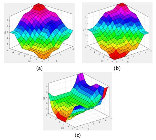
Figure 11.
(a) Fuzzy control rules for ∆Kp; (b) fuzzy control rules for ∆Ki; (c) fuzzy control rules for ∆Kd.
4.3.2. PID Controller Correction
The appropriate selection of quantization factor and scale factor has the same impact on the control effect of the fuzzy PID controller. The general formula for calculating quantization factors is shown in Equation (22), and the formula for calculating scaling factors is shown in Equation (23):
where Ke is the quantization factor, N is the fuzzy domain of the input variable, and Xe is the fundamental domain of the input variable.
Among them, Ku is the scaling factor, Y is the fundamental domain of the output variable, and Lu is the fuzzy domain of the output variable.
Moreover, to enhance the controller’s performance under large-scale dynamic disturbances, an adaptive scaling factor adjustment mechanism is integrated into the system. Specifically, when the absolute values of the error e and its rate of change ec are detected to be concurrently in a large range, the system dynamically reduces the input quantization coefficients Ke and Kec, while simultaneously increasing the output control quantity’s scaling factor Ku. This strategy is designed to implement a more decisive control intervention by reducing sensitivity to inputs and amplifying the magnitude of the control output when the system state deviates significantly from the setpoint, thereby optimizing the transient response characteristics.
4.3.3. PID Controller Correction
By using the above fuzzy control strategy, PID parameters can be adjusted online based on real-time state inputs during the control process. The adjustment rules are as follows:
where, Kp0, Ki0, and Kd0 are the initial values of the PID controller.
4.3.4. Defuzzification
The fuzzy language output by the fuzzy controller must be defuzzified to obtain the final control quantity as the output. This article adopts the centroid method. For an output fuzzy set C composed of multiple fuzzy rules, its membership function is μC (x). The calculation formula of the centroid method is
After system adjustment, the final parameter values are determined as shown in Table 2.
Table 2.
Adjusted system parameters.
4.4. Propulsion System Simulation and Analysis
4.4.1. Promote System Parameter Setting
The propulsion system component selection was calculated by the design manual and its key parameters, as shown in Table 3.
Table 3.
Propulsion system key parameters.
4.4.2. Promote the Setting of Ideal Displacement Curve
With the increase in drilling depth, the drilling rock load shows a nonlinear growth trend. Based on the engineering reality of continuous drilling of drilling rigs under stable geological conditions, the actual load curve of drilling is shown in Figure 12a: FL—push load; t—operation time; Δta—drilling time period; Δtb—connecting drill pole time period [28]. And in the control simulation of the propulsion system, it is necessary to ensure that the simulated load control curve maintains a dynamic match with the actual working load curve of the drilling rig, in which the ideal control curve of propulsion displacement is shown in Figure 12b: Δtc—drill pipe unloading time period; Δtd—power head return to initial position time period; Δtd—time period for drill pipe extension.
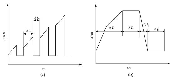
Figure 12.
(a) Actual load curve of drilling rig drilling; (b) ideal control curve for propulsion displacement.
4.4.3. Joint Simulation and Analysis
A co-simulation between AMESim and MATLAB/Simulink was conducted, employing two distinct control strategies. The simulation yielded a series of comparative plots to evaluate system performance, including: the propulsion load, speed, and displacement of the hydraulic cylinders relative to the power head under conventional PID control; the tracking of the ideal displacement trajectory by the hydraulic cylinders under different control strategies; the corresponding displacement tracking errors; and the propulsion speed profiles of the hydraulic cylinders and the power head, along with the speed synchronization error curve. These results are presented in Figure 13, Figure 14, Figure 15 and Figure 16.
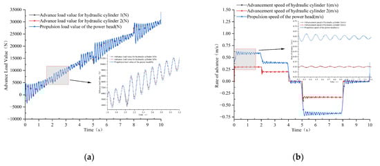
Figure 13.
(a) Comparison curve of hydraulic cylinder and powerhead propulsion loads with conventional PIDs; (b) comparison curves of hydraulic cylinder and power head propulsion speeds with conventional PIDs.
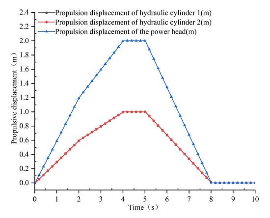
Figure 14.
Comparison curve of hydraulic cylinder and power head propulsion displacement with conventional PID.
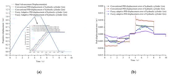
Figure 15.
(a) Tracking ideal displacement curves of hydraulic cylinders with different control strategies; (b) displacement and ideal displacement error of hydraulic cylinders with different control strategies.
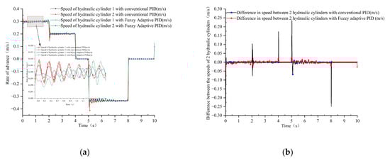
Figure 16.
(a) Advance velocity curve of hydraulic cylinder and power head; (b) propulsion velocity difference curve.
The simulation results verifying the fundamental mechanical characteristics of the mechano-hydraulic composite propulsion system are presented in Figure 13 and Figure 14. From a dynamics perspective, the results demonstrate that the two parallel hydraulic cylinders achieve a balanced distribution of the propulsion load, with the sum of their individual loads corresponding precisely to the total load on the power head; this is consistent with the analytical mechanics model based on the pulley system. From a kinematics perspective, the propulsion displacement and velocity of the power head exhibit a deterministic 2:1 multiplication ratio relative to the output of a single hydraulic cylinder. The high degree of consistency between the simulation data and the theoretically derived mathematical model thoroughly validates the feasibility and correctness of the novel propulsion apparatus design in both the dynamic and kinematic domains.
After the simulation and comparative analysis of the two control strategies, it can be seen from Figure 15a that the fuzzy adaptive PID control has a better load tracking effect than the traditional PID control, and there is a certain fluctuation in the difference of the propulsion displacement of the two control strategies. From Figure 15b, a table of the error values of the hydraulic cylinder displacement compared to the ideal propulsion displacement can be derived, as shown in Table 4. From Table 4, it can be seen that the control accuracy of hydraulic cylinder No. 1 with fuzzy adaptive PID reaches 2.3 mm, and the control accuracy of hydraulic cylinder No. 2 with fuzzy adaptive PID reaches 5.6 mm, which improves the error of control by 63.49% and 46.15%, respectively, compared with the traditional PID control algorithm. From Figure 13a and Figure 16a,b, it can be seen that when the drilling rig works with the increase in drilling depth, the propulsion load and the propulsion speed increase.
Table 4.
Error value of displacement comparison.
4.5. Experimental Prototype Display
This study proposes a position-feedback-based control strategy for a mechano-hydraulic electro-hydraulic proportional propulsion system, designed to address the challenges of transportation, deployment, and adaptability of conventional drilling rigs in complex environments such as high-altitude regions. A key innovation in the system’s mechanical architecture is the composite design of parallel hydraulic cylinders coupled with a movable pulley system. This configuration achieves a lightweight design by leveraging a displacement multiplication effect to significantly reduce the system’s dimensions and mass while maintaining the required operational stroke. The technical feasibility and reliability of the proposed control strategy were subsequently validated through mathematical modeling and co-simulation. To further demonstrate its engineering practicality, an experimental prototype was developed. As illustrated in Figure 17, the prototype features a compact transport mode, facilitating its conveyance to designated operational sites. Figure 18 shows the system in its deployed operational mode, displaying its full working configuration. Furthermore, the design incorporates an interchangeable power head, enhancing the system’s adaptability to diverse geological conditions.
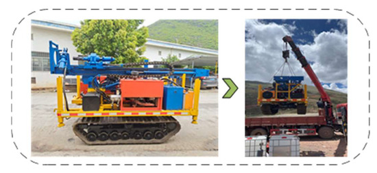
Figure 17.
Shrink transport model.
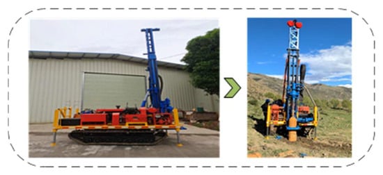
Figure 18.
Expand work model.
5. Discussion
This section systematically elaborates on the research discussion and future prospects of the mechanical hydraulic hybrid propulsion system from four dimensions: firstly, it verifies the previous research foundation and working hypotheses; secondly, it analyzes and explains the research results from multiple dimensions; then, it elaborates on the broad impact and industry significance of the research findings; and finally, it points out the future research directions.
5.1. Verification of Previous Research Foundations and Working Hypotheses
The existing engineering drilling rig propulsion system generally faces two major technical bottlenecks. (1) Mechanical structural limitations: The traditional hydraulic cylinder direct drive mode results in a linear increase in system mass and size with the operating stroke, making it difficult to adapt to the stringent requirements of high-altitude transportation (such as helicopter lifting quality limitations and rough terrain transportation space constraints). (2) Control strategy deficiency: Traditional PID control is difficult to balance response speed and control accuracy in high-altitude environments (temperature fluctuations, hydraulic oil viscosity fluctuations, and nonlinear load changes) due to fixed parameters.
Mechanical structure verification: The experimental prototype achieved a 2:1 stroke amplification through a pulley system, reducing the cylinder diameter of the hydraulic cylinder and directly verifying the feasibility of the lightweight assumption. Control strategy verification: Fuzzy adaptive PID improves the positioning accuracy of hydraulic cylinders 1 and 2 to 2.3 mm and 5.6 mm, respectively (traditional PID is 6.3 mm and 10.4 mm), and reduces overshoot by 58% during sudden load changes in dynamic response, confirming the robustness of adaptive control to complex high-altitude working conditions.
5.2. Interpretation of Results and Multidimensional Analysis
The composite structure of the pulley system and parallel hydraulic cylinder is essentially a synergistic effect of kinematic amplification and force flow reconstruction. Displacement multiplier effect: The pulley system amplifies the linear displacement of the hydraulic cylinder piston rod by 2 times through rope winding (such as extending the hydraulic cylinder by 1 m and achieving a 2 m stroke of the power head), allowing the use of short-stroke hydraulic cylinders to meet the requirements of long-stroke operations. Load distribution characteristics: Mathematical model derivation shows that the parallel design of dual hydraulic cylinders evenly distributes the load of the power head (error ≤ 5%), avoiding the problem of unbalanced load in single cylinder drive, which provides a mechanical basis for the miniaturization of hydraulic cylinders.
The core logic of balancing the response speed and control accuracy of the PID controller is that the rapid response is driven by the proportional coefficient Kp, the steady-state error is eliminated by the integral coefficient Ki, and the overshoot is suppressed by the differential coefficient Kd, which work together to form a dynamic balance at the parameter level. Combined with the quantitative correlation of rise time, overshoot, steady-state error, and other indicators, the system can quickly track the target (e.g., shorten the response delay when the drilling rig is started) and control the error (e.g., reduce the cylinder positioning error in the steady-state) under different working conditions through subsection setting (giving priority to Kp and Kd in the dynamic phase and strengthening Ki in the steady-state phase), and adjusting the parameters in real time according to the deviation, so as to achieve the dual goals of fast dynamic response and high steady-state accuracy. However, once the parameters of the traditional PID controller are set, they are fixed and cannot cope with parameter fluctuations: when KP increases by 20% due to the decrease in hydraulic oil viscosity (e.g., temperature rise), the sensitivity of the system to deviation rises sharply, which will lead to the overshoot of the hydraulic cylinder from 5% to 25%, and the vibration caused by the impact of the power head on the drilling tool, and even the bending of the drill pipe. When KP decreases by 20% due to valve port wear, the system response delay increases, and the tracking error expands (beyond the allowable range of the project), which cannot meet the requirements of drilling accuracy.
In the nonlinear working conditions of high-altitude environments (such as hydraulic oil compressibility fluctuations caused by pressure changes above 4000 m altitude), the rule self-adjusting characteristics of fuzzy control solve the three major limitations of traditional PID. (1) Parameter time-varying problem: Through real-time feedback of error (e) and error change rate (ec), we dynamically adjust ΔKp/ΔKi/ΔKd. For example, when e > 5 mm and ec > 2 mm/s, we automatically increase ∆Kp from PS to PM to accelerate response speed. (2) Hysteresis nonlinear compensation: Friction and leakage in hydraulic systems lead to static errors in traditional PID, while the design of “ΔKi = PS when e = Z and ec = Z” in the fuzzy rule table slowly eliminates steady-state errors through integral terms (steady-state errors were reduced from 1.8 mm to 0.5 mm in the experiment). (3) Anti-interference robustness: When the load suddenly changes (such as encountering hard rock causing a sudden increase in resistance), fuzzy control suppresses system oscillation by increasing ΔKd, while traditional PID suffers from an overshoot of up to 15% due to fixed parameters (fuzzy control is only 6%).
5.3. Broad Impact and Industry Significance of Research Findings
Breakthrough in high-altitude operations: The compact contraction transportation mode (reducing volume by 60%) allows drilling rigs to be airdropped to unmanned areas by helicopters, filling the gap in traditional equipment operations in complex terrains such as the Qinghai Tibet Plateau and the Hengduan Mountains. Cost and efficiency optimization: Lightweight design reduces transportation costs by 30–50%, while power head replacement design (compatible with six types of drill bits such as core drills and rotary drills) doubles equipment utilization, providing an economical and efficient solution for mineral resource exploration and plateau infrastructure.
5.4. Future Research Directions
Fusion in-depth learning: An LSTM neural network is introduced to predict plateau environmental parameters (temperature and pressure), and the fuzzy rule table is adjusted in advance to further improve the control accuracy under extreme conditions (goal: synchronization error ≤ 1 mm). Distributed collaborative control: Research on multi cylinder collaborative strategy based on model predictive control (MPC) for multi drilling rig cluster operation scenarios, is needed to solve the phase difference problem during synchronous operation of multiple machines.
6. Conclusions
- (1)
- To address the critical issues of excessive mass and poor load adaptability in existing engineering drilling rig propulsion systems, this study proposes a control strategy for a mechano-hydraulic composite electro-hydraulic proportional propulsion system based on position feedback. The technical feasibility and reliability of this scheme were validated through the establishment of a system mathematical model and comparative co-simulation analysis. This research provides essential theoretical support and technical guidance for the design of propulsion systems for engineering drilling rigs.
- (2)
- To theoretically elucidate the design principles of the mechano-hydraulic composite propulsion system, a comprehensive mathematical model was developed, from which the transfer functions of key components were derived. The model’s primary purpose was to validate the core design objective: achieving system lightweighting via a displacement multiplication effect enabled by the pulley system. The analysis confirms that the composite structure establishes a deterministic 2:1 stroke amplification ratio through kinematic magnification, providing a robust theoretical foundation for reducing hydraulic cylinder dimensions without compromising operational stroke. Additionally, the model verifies the uniform distribution of the power head’s total load across the two parallel cylinders and establishes the direct relationship between system output displacement and the electro-hydraulic proportional valve’s spool position.
- (3)
- To evaluate system performance, this study conducted a comparative simulation analysis of two control strategies: conventional PID and fuzzy adaptive PID. The results indicate that while both strategies can drive the hydraulic cylinders to track the ideal displacement, the fuzzy adaptive PID control strategy demonstrates a significantly superior performance. Under this strategy, the final positioning accuracies of cylinder 1 and cylinder 2 reached 2.3 mm and 5.6 mm, respectively, representing precision improvements of 63.49% and 46.15% compared to conventional PID control. Dynamic response analysis further confirms that the fuzzy adaptive PID controller possesses superior tracking robustness under nonlinear conditions, such as abrupt load changes.
- (4)
- Experimental investigation into the impact of regional environmental conditions on the synchronous control of drilling rigs reveals that high-altitude (4000 m) operation fundamentally alters the engine’s dynamic characteristics, necessitating the use of adaptive control methods to achieve high-precision synchronization. Our findings indicate a significant and temperature-dependent power loss of up to 29.8%, alongside pronounced instability in the low-speed range, which contrasts with the reliable performance observed in the medium-to-high speed range. These experimentally determined characteristics form the basis for designing a robust position-feedback synchronous control system. A successful control architecture must possess dual adaptive capabilities: (1) strategically selecting operational setpoints to avoid the unstable low-speed range while leveraging the stable output of the medium-to-high speed range; (2) dynamically adjusting its parameters to offset performance degradation and nonlinear effects induced by altitude and temperature variations. Therefore, the successful implementation of high-precision synchronization in such challenging environments hinges upon an intelligent control framework designed to actively suppress power input fluctuations and compensate for environmentally-induced performance degradation.
Author Contributions
Conceptualization, Z.L. and Y.L.; methodology, S.L. and Y.L.; validation, H.Z.; investigation, S.L. and D.W.; writing—original draft preparation, S.L. and Y.L.; project administration, Z.L. and H.Z. All authors have read and agreed to the published version of the manuscript.
Funding
This research was funded by National Natural Science Foundation of China (51765014); Natural Science Foundation of Guangxi (2025GXNSFAA069959); “Sichuan--Tibet Railway Transmission Project” commissioned by CEC-Sichuan Electric Power Design and Consulting Co. (SEDC-2024-WW-00432).
Data Availability Statement
The original contributions proposed in this study are included in the article. For further inquiries, contact the corresponding author directly.
Conflicts of Interest
Author Yuanzhou Li was employed by the company Shenzhen Huichuan Intelligent Control Pneumatic Technology Co., Ltd. The remaining authors declare that the research was conducted in the absence of any commercial or financial relationships that could be construed as a potential conflict of interest.
Abbreviations
The following abbreviations are used in this manuscript:
| FLC | Fuzzy Logic Controller |
| gaussmf | Gaussian membership function |
| trimf | Triangular membership function |
| LSTM | Long Short-Term Memory |
| PID | Proportional-Integral-Derivative |
| MPC | Model Predictive Control |
| NB | Negative Big |
| NM | Negative Medium |
| NS | Negative Small |
| Z | Zero |
| PS | Positive Small |
| PM | Positive Medium |
| PB | Positive Big |
References
- Zhang, B.; Cao, X.Y.; Zhou, T.M.; Xia, H. Discussion on the Current Situation and Development Trend of Drilling Equipment Technology for Deep and Ultra—Deep Wells. Drill. Prod. Technol. 2024, 47, 141–151. [Google Scholar]
- Wu, W.R.; Xu, Z.; Shi, J. Research on the Propulsion System of Hydraulic Drilling Rig Based on High—Speed On—Off Valves. Comput. Simul. 2014, 31, 201–205, 303. [Google Scholar] [CrossRef]
- Meng, X.H. Optimization of Propulsion Force Output Efficiency of High—Power Directional Drilling Rig. Coal Mine Mach. 2020, 41, 114–116. [Google Scholar] [CrossRef]
- Chen, W.Y.; Liu, R.J.; Ni, J.Z. Modular Design of Mountain Mini-Pile Drilling Rig. Strait Sci. 2024, 1, 39–42. [Google Scholar]
- Yao, Z.T.; Xiang, Y.; Zeng, L.X.; Wang, C.; Zhu, C.; Xue, X.; Shang, L. Modified Design of Portable Drilling Rig Suitable for Overburden Drilling. Geol. Equip. 2024, 25, 1–6. [Google Scholar] [CrossRef]
- Li, L.Z.; Li, X.M.; Wang, Z.T.; Liu, X. Innovative Technology and Application of 3000 m Fast—Moving and Fast—Installing Drilling Rig. China Pet. Mach. 2021, 49, 58–63. [Google Scholar] [CrossRef]
- Han, J.W. Design of Movable Hydraulic Power Unit for All—Hydraulic Rotary Drilling Rig. Mach. Tool Hydraul. 2023, 51, 136–141. [Google Scholar]
- Wang, X.; Liu, R.; Liu, Q.; Zhang, Y. Research on tool carts based on modular drilling rig assembly. J. Phys. Conf. Ser. 2023, 2433, 012040. [Google Scholar] [CrossRef]
- Liu, Z.; Li, Y.Z.; Wei, Z.X.; Huang, J.C.; Lü, Y.; Li, H.X.; Zhang, Y.; Xiong, Z.G. Crawler-Type Walking Device. CN202111238592.7, 31 December 2021. [Google Scholar]
- Wang, H.; Fan, D.; Weng, Y. Research on control system of truck-mounted rig for coalbed methane. MATEC Web Conf. 2018, 153, 04001. [Google Scholar] [CrossRef]
- Chen, Y.-L.; Shang, T.; Li, J.; Nie, G.; Sui, H.; Chen, X. Evaluation for Energy—Saving Effect of Hybrid Drilling Rig System Based on the Logic Threshold Method. J. Terramechanics 2016, 63, 49–60. [Google Scholar] [CrossRef]
- Li, Y.; Liu, Z.; Xiong, Z.; Chen, Z.; Cai, J. Research on PID control strategy of power head propulsion system of engineering hydraulic drilling rig. J. Phys. Conf. Ser. 2023, 2483, 012043. [Google Scholar] [CrossRef]
- Liang, X.; Wu, W. Control strategy of energy saving for power system in hydraulic surface drilling rig. J. Braz. Soc. Mech. Sci. Eng. 2018, 40, 282. [Google Scholar] [CrossRef]
- Jia, C.D.; Zhao, Z.W.; Kong, X.D.; Zhang, Z.; Xu, H.; Ai, C. Research on anti-interference control of rotary drilling rig traveling system under time-varying load. J. Mech. Eng. 2024, 61, 413–422. [Google Scholar]
- Xu, X.; Tang, Q.J.; Ren, K.; Zhang, D.; Zhou, E. Analysis of construction process and research on control strategy of rotary drilling rig. J. Mech. Electr. Eng. 2023, 40, 1907–1914. [Google Scholar] [CrossRef]
- Ji, H.; Liu, S. Position deviation control of drilling machine using a nonlinear adaptive backstepping controller based on a disturbance observer. Processes 2021, 9, 237. [Google Scholar] [CrossRef]
- Zhang, Y.; Chang, J.; Fan, D.; Tian, H. Research on intelligent control algorithm for automatic drilling of vehicle-mounted rig. J. Phys. Conf. Ser. 2020, 1650, 032037. [Google Scholar] [CrossRef]
- Zhang, Z.; Guo, Y.N.; Zhu, S.; Jiao, F.; Gong, D. Global terminal sliding mode finite-time speed control for hydraulic rock bolt drill based on adaptive observer. Sci. Sin. Informationis 2024, 54, 1884–1906. [Google Scholar] [CrossRef]
- Wu, J.B.; Li, L.; Yan, Y.K.; Wang, P.J.; Wei, W. An energy-saving position control strategy for deep-sea valve-controlled hydraulic cylinder systems. J. Mar. Sci. Eng. 2022, 10, 567. [Google Scholar] [CrossRef]
- He, D.; Wang, T.; Wang, J.; Ren, Z.; Gao, X. Research on the position–pressure cooperative control strategy for full-hydraulic leveler. Adv. Mech. Eng. 2018, 10, 04001. [Google Scholar] [CrossRef]
- Zhu, Z.; Cao, P. Optimization research on drilling control system of large auger drilling rig based on IPSO. Coal Technol. 2023, 42, 213–217. [Google Scholar] [CrossRef]
- Wang, J.; Ma, W.H.; Xie, T.L.; Guo, H.; Yin, B. Design and Experiment of Hydraulic System for a New Dual—Clutch Full—Power Shift Transmission of Heavy—Duty Tractor. J. Jilin Univ. (Eng. Technol. Ed.) 2025, 55, 1806–1816. [Google Scholar]
- Li, Y.; Li, R.; Yang, J.; Yu, X.; Xu, J. Review of recent advances in the drive method of hydraulic control valve. Processes 2023, 11, 2537. [Google Scholar] [CrossRef]
- Ren, Y.F.; Xi, J.Q.; Chen, H.Y.; Yu, H.; Meng, F.; Zhou, W. Time—Frequency Domain Modeling and Analysis of Pilot—Type Electro—Hydraulic Pressure—Regulating Valve for Wet Clutch. Acta Armamentarii 2023, 44, 222–232. [Google Scholar]
- Li, X.X.; Wang, A.L.; Fan, X.C.; Li, X. Dynamic Characteristic Model and Design of Proportional Solenoid Valve for Clutch Engagement Process. J. Xi’an Jiaotong Univ. 2020, 54, 46–52. [Google Scholar] [CrossRef]
- Zhang, W.; Yuan, Q.; Xu, Y.; Wang, X.; Bai, S.; Zhao, L.; Hua, Y.; Ma, X. Research on control strategy of electro-hydraulic lifting system based on AMESim and MATLAB. Symmetry 2023, 15, 435. [Google Scholar] [CrossRef]
- Yao, R.; Bai, H.; Zhang, Y.; Cen, B.; Zou, H. Denoising Method of a Power Quality Signal Based on Parameter Coordination of Membership Function in Fuzzy Logic Theory. Processes 2025, 13, 738. [Google Scholar] [CrossRef]
- Liu, W.L.; Li, Z.J.; Zhang, G.F.; Qin, G.; Wang, Q.; Yang, Y. Testing Method for Drilling Rig Based on Real Working Condition Simulation Load Technology. Min. Saf. Environ. Prot. 2013, 40, 56–58. [Google Scholar]


Disclaimer/Publisher’s Note: The statements, opinions and data contained in all publications are solely those of the individual author(s) and contributor(s) and not of MDPI and/or the editor(s). MDPI and/or the editor(s) disclaim responsibility for any injury to people or property resulting from any ideas, methods, instructions or products referred to in the content. |
© 2025 by the authors. Licensee MDPI, Basel, Switzerland. This article is an open access article distributed under the terms and conditions of the Creative Commons Attribution (CC BY) license (https://creativecommons.org/licenses/by/4.0/).