
Constant Power Charging Control Method for Isolated Vehicle-to-Vehicle Energy Transfer Converter

Abstract
1. Introduction
2. System Modeling of V2V Device Based on DAB
2.1. DAB Basic Characteristics
2.2. System Modeling
3. CPC Control Without Current Sensors
3.1. Design of FTDO
3.2. Design of Backstepping Controller
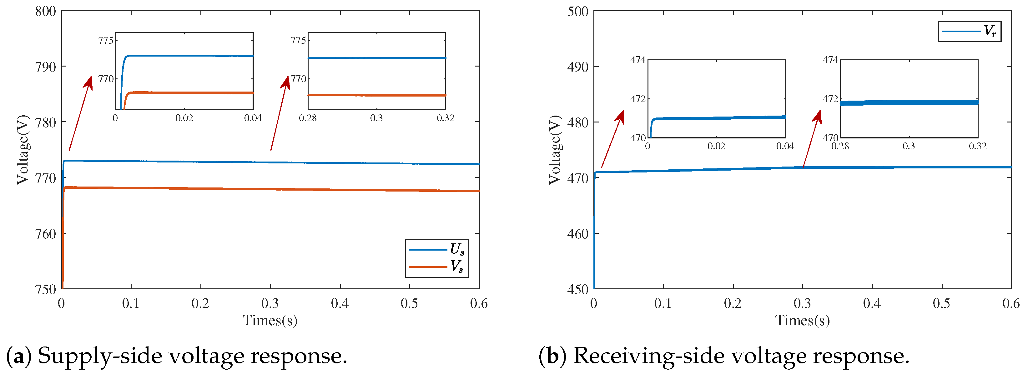
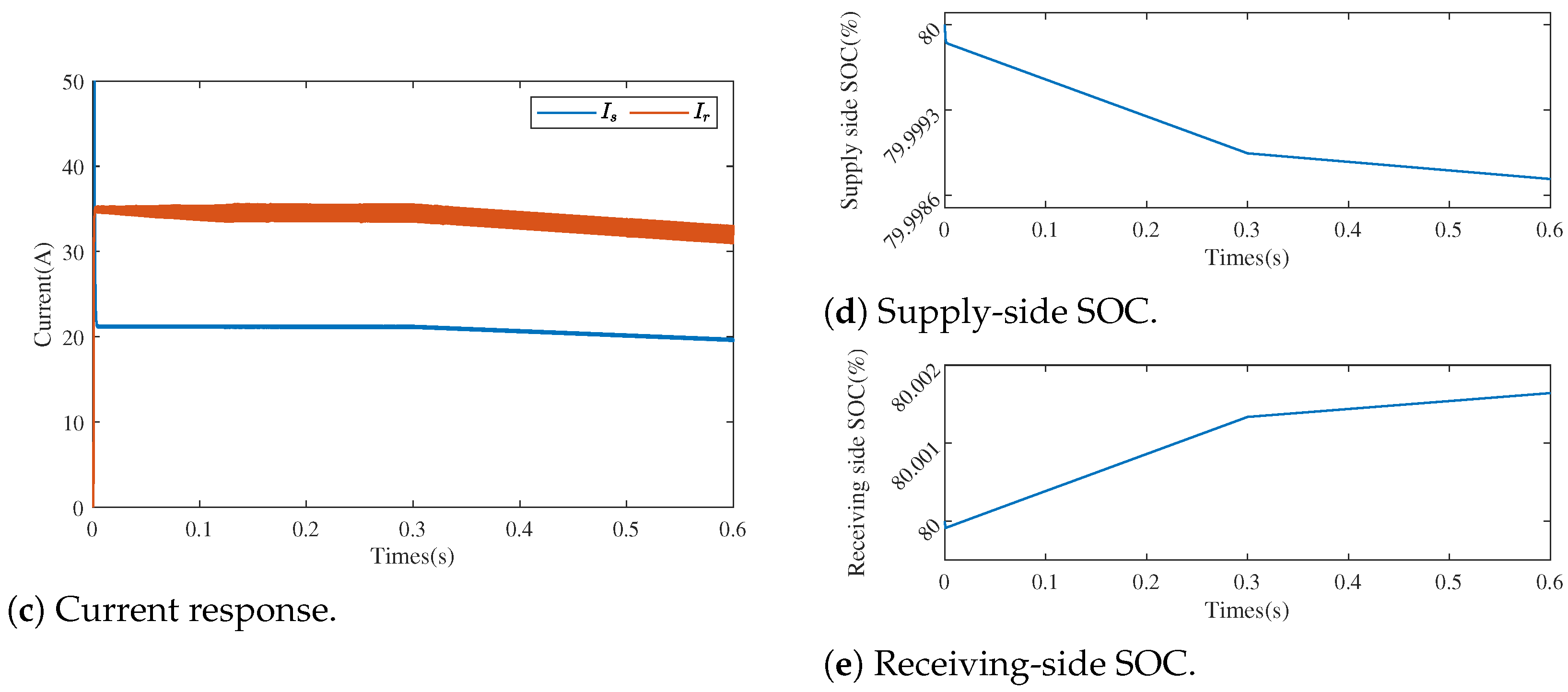
4. Simulation
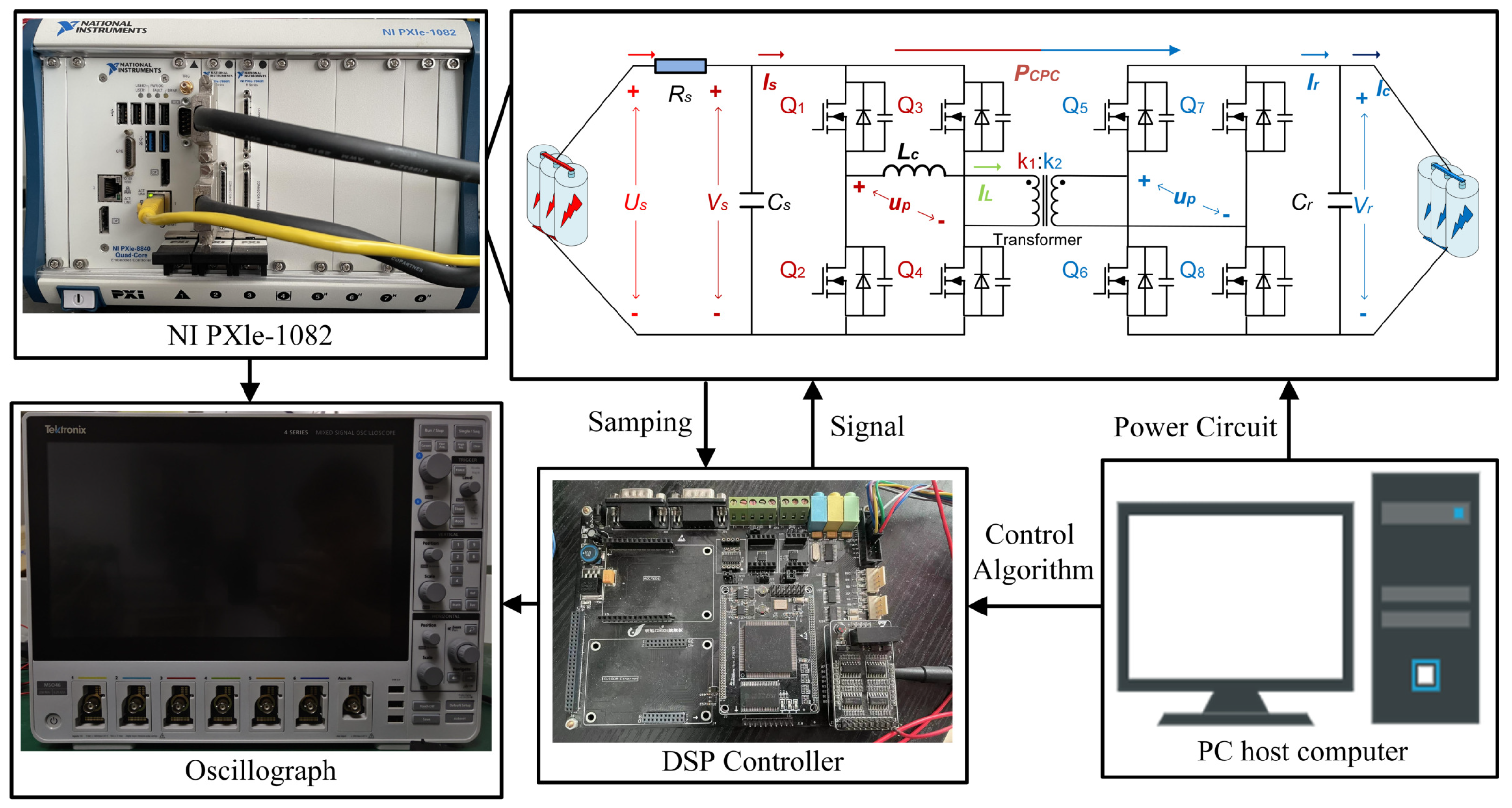
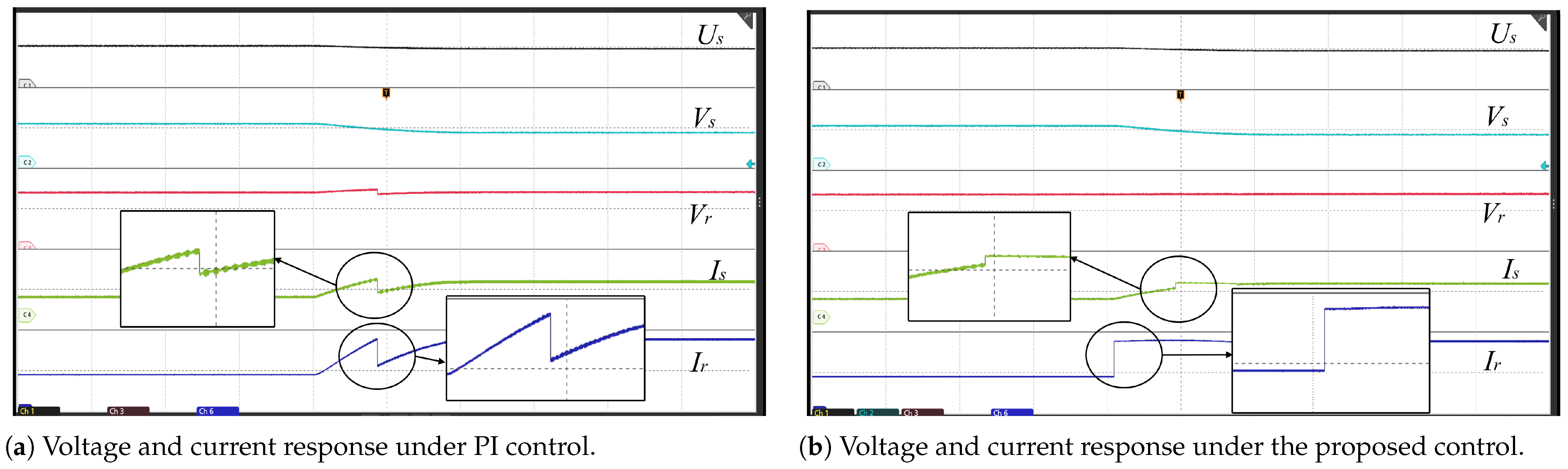
5. Experiments
6. Conclusions
Author Contributions
Funding
Data Availability Statement
Conflicts of Interest
References
- Un-Noor, F.; Padmanaban, S.; Mihet-Popa, L.; Mollah, M.N.; Hossain, E. A Comprehensive Study of Key Electric Vehicle (EV) Components, Technologies, Challenges, Impacts, and Future Direction of Development. Energies 2017, 10, 1217. [Google Scholar] [CrossRef]
- Sanguesa, J.A.; Torres-Sanz, V.; Garrido, P.; Martinez, F.J.; Marquez-Barja, J.M. A Review on Electric Vehicles: Technologies and Challenges. Smart Cities 2021, 4, 372–404. [Google Scholar] [CrossRef]
- Nyamathulla, S.; Dhanamjayulu, C. A Review of Battery Energy Storage Systems and Advanced Battery Management System for Different Applications: Challenges and Recommendations. J. Energy Storage 2024, 86, 111179. [Google Scholar] [CrossRef]
- Vengatesan, S.; Jayakumar, A.; Sadasivuni, K.K. FCEV vs. BEV—A short overview on identifying the key contributors to affordable & clean energy (SDG-7). Energy Strateg. Rev. 2024, 53, 101380. [Google Scholar] [CrossRef]
- International Energy Agency. Global EV Outlook 2023. Available online: https://www.iea.org/reports/global-ev-outlook-2023 (accessed on 1 July 2024).
- Xu, J.; Cai, X.; Cai, S.; Shao, Y.; Hu, C.; Lu, S.; Ding, S. High-Energy Lithium-Ion Batteries: Recent Progress and a Promising Future in Applications. Energy Environ. Mater. 2023, 6, e12450. [Google Scholar] [CrossRef]
- He, Z.; Huang, Y.; Liu, H.; Geng, Z.; Li, Y.; Li, S.; Deng, W.; Zou, G.; Hou, H.; Ji, X. Anode materials for fast charging sodium-ion batteries. Nano Energy 2024, 129, 109996. [Google Scholar] [CrossRef]
- Khalatbarisoltani, A.; Zhou, H.; Tang, X.; Kandidayeni, M.; Boulon, L.; Hu, X. Energy Management Strategies for Fuel Cell Vehicles: A Comprehensive Review of the Latest Progress in Modeling, Strategies, and Future Prospects. IEEE Trans. Intell. Transp. Syst. 2024, 25, 14–32. [Google Scholar] [CrossRef]
- Wang, R.; Liu, H.; Li, M.-J.; Sun, Q.; Li, X.; Wang, P. Fast Charging Control Method for Electric Vehicle-to-Vehicle Energy Interaction Devices. IEEE Trans. Transp. Electrif. 2023, 9, 4941–4950. [Google Scholar] [CrossRef]
- Cao, Y.; Cui, J.; Liu, S.; Li, X.; Zhou, Q.; Hu, C. A Holistic Review on E-Mobility Service Optimization: Challenges, Recent Progress, and Future Directions. IEEE Trans. Transp. Electrif. 2024, 10, 3712–3741. [Google Scholar] [CrossRef]
- Wen, J.; Gan, W.; Chu, C.-C.; Wang, J.; Jiang, L. Cooperative V2G-enabled vehicle-to-vehicle sharing in energy and reserve markets: A coalitional approach. Appl. Energy 2024, 376, 124311. [Google Scholar] [CrossRef]
- Xu, Y.; Ge, X.; Guo, R.; Shen, W. Online Soft Short-Circuit Diagnosis of Electric Vehicle Li-Ion Batteries Based on Constant Voltage Charging Current. IEEE Trans. Transp. Electrif. 2023, 9, 2618–2627. [Google Scholar] [CrossRef]
- Duru, K.K.; Karra, C.; Venkatachalam, P.; Betha, S.A.; Madhavan, A.A.; Kalluri, S. Critical Insights Into Fast Charging Techniques for Lithium-Ion Batteries in Electric Vehicles. IEEE Trans. Device Mater. Reliab. 2021, 21, 137–152. [Google Scholar] [CrossRef]
- Ji, D.; Chen, L.; Ma, T.; Wang, J.; Liu, S.; Ma, X.; Wang, F. Research on adaptability of charging strategy for electric vehicle power battery. J. Power Sources 2019, 437, 226911. [Google Scholar] [CrossRef]
- Chen, G.-J.; Chung, W.-H. Evaluation of Charging Methods for Lithium-Ion Batteries. Electronics 2023, 12, 4095. [Google Scholar] [CrossRef]
- Xu, F.; Wong, S.-C.; Tse, C.K. Overall Loss Compensation and Optimization Control in Single-Stage Inductive Power Transfer Converter Delivering Constant Power. IEEE Trans. Power Electron. 2022, 37, 1146–1158. [Google Scholar] [CrossRef]
- Wang, R.; Sun, Q.; Hu, W.; Li, Y.; Ma, D.; Wang, P. SoC-Based Droop Coefficients Stability Region Analysis of the Battery for Stand-Alone Supply Systems with Constant Power Loads. IEEE Trans. Power Electron. 2021, 36, 7866–7879. [Google Scholar] [CrossRef]
- Iam, I.-W.; Choi, C.-K.; Lam, C.-S.; Mak, P.-I.; Martins, R.P. A Constant-Power and Optimal-Transfer-Efficiency Wireless Inductive Power Transfer Converter for Battery Charger. IEEE Trans. Ind. Electron. 2024, 71, 450–461. [Google Scholar] [CrossRef]
- Dong, X.; Zhang, H.; Xie, X.; Ming, Z. Data-Driven Distributed H∞ Current Sharing Consensus Optimal Control of DC Microgrids via Reinforcement Learning. IEEE Trans. Circuits Syst. I 2024, 71, 2824–2834. [Google Scholar] [CrossRef]
- Chen, J.; Xu, Y.; Lu, H.; Yan, Z.; Yu, Z.; Li, Q. Fixed Frequency LCC Resonant Converter Modeling and Optimal Design for High-Voltage Capacitor Charging Power Supply in Constant Power Control. IEEE Trans. Ind. Appl. 2023, 59, 4287–4299. [Google Scholar] [CrossRef]
- Zhang, K.; Zhang, P.; Du, H.; Yan, Z.; Song, B.; Hu, A.P. Robust Control of IPT System for Constant Current Charging Under Multiple Parameter Perturbations. IEEE Trans. Ind. Appl. 2022, 58, 1168–1178. [Google Scholar] [CrossRef]
- Wang, R.; Sun, Q.; Sun, C.; Zhang, H.; Gui, Y.; Wang, P. Vehicle-Vehicle Energy Interaction Converter of Electric Vehicles: A Disturbance Observer Based Sliding Mode Control Algorithm. IEEE Trans. Veh. Technol. 2021, 70, 9910–9921. [Google Scholar] [CrossRef]
- Nkembi, A.A.; Santoro, D.; Ahmad, F.; Kortabarria, I.; Cova, P.; Sacchi, E.; Delmonte, N. Novel Droop-Based Techniques for Dynamic Performance Improvement in a Linear Active Disturbance Rejection Controlled-Dual Active Bridge for Fast Battery Charging of Electric Vehicles. Energies 2024, 17, 5171. [Google Scholar] [CrossRef]
- Wang, Z.; Su, X.; Zeng, N.; Jiang, J. Overview of Isolated Bidirectional DC–DC Converter Topology and Switching Strategies for Electric Vehicle Applications. Energies 2024, 17, 2434. [Google Scholar] [CrossRef]
- Liu, L.; Tang, J.; Yang, S.; Qian, B.; Wu, Q.; Zhou, M.; Jun, P.; Zhang, F. An Ultra-High Voltage AC/DC Isolated Matrix Converter Applied to V2G Electric Vehicle Charging Piles. Int. J. Circuit Theory Appl. 2024. [Google Scholar] [CrossRef]
- Gupta, J.; Singh, B. A Fully Bridgeless Bidirectional Single Stage Isolated Battery Charger-Cum-Domestic Inverter System for LEVs Application. IEEE Trans. Ind. Appl. 2024, 60, 7193–7205. [Google Scholar] [CrossRef]
- Cheng, Z.; He, L.; Zhou, H. Optimal Triple-Phase-Shift Modulation Strategy for Wide-Gain High-Efficiency Bidirectional CLLC Converter. IEEE Trans. Transp. Electrif. 2025, 11, 5867–5879. [Google Scholar] [CrossRef]
- Wang, X.; Wei, X.; Chen, Q.; Dai, H. A Novel System for Measuring Alternating Current Impedance Spectra of Series-Connected Lithium-Ion Batteries with a High-Power Dual Active Bridge Converter and Distributed Sampling Units. IEEE Trans. Ind. Electron. 2021, 68, 7380–7390. [Google Scholar] [CrossRef]
- Everts, J.; Krismer, F.; Van den Keybus, J.; Driesen, J.; Kolar, J.W. Optimal ZVS Modulation of Single-Phase Single-Stage Bidirectional DAB AC–DC Converters. IEEE Trans. Power Electron. 2014, 29, 3954–3970. [Google Scholar] [CrossRef]
- Jiang, Y.; Li, Y.; Yang, J.; Shu, X. A Review of Research on Dual-Side Control Methods for Magnetic Coupling Wireless Power Transfer Systems Based on Dual-Active Bridge Converters. Electronics 2024, 13, 4765. [Google Scholar] [CrossRef]
- Demirci, O.; Taskin, S.; Schaltz, E.; Demirci, B.A. Review of battery state estimation methods for electric vehicles—Part I: SOC estimation. J. Energy Storage 2024, 87, 111435. [Google Scholar] [CrossRef]
- Ding, C.; Ding, S.; Wei, X.; Ji, X.; Sun, J.; Mei, K. Disturbance-Observer-Based Barrier Function Adaptive Sliding Mode Control for Path Tracking of Autonomous Agricultural Vehicles with Matched-Mismatched Disturbances. IEEE Trans. Transp. Electrif. 2024, 10, 6748–6760. [Google Scholar] [CrossRef]
- Zheng, C.; Dragičević, T.; Blaabjerg, F. Current-Sensorless Finite-Set Model Predictive Control for LC-Filtered Voltage Source Inverters. IEEE Trans. Power Electron. 2020, 35, 1086–1095. [Google Scholar] [CrossRef]
- Chen, X.; Xu, G.; Han, H.; Liu, D.; Sun, Y.; Su, M. Light-Load Efficiency Enhancement of High-Frequency Dual-Active-Bridge Converter Under SPS Control. IEEE Trans. Ind. Electron. 2021, 68, 12941–12946. [Google Scholar] [CrossRef]
- Pal, P.; Behera, R.K.; Muduli, U.R. Eliminating Current Sensor Dependencies in DAB Converters Using a Luenberger Observer-Based Hybrid Approach. IEEE Trans. Ind. Appl. 2024, 60, 6380–6392. [Google Scholar] [CrossRef]
- Tiwary, N.; Naik, V.N.; Panda, A.K.; Narendra, A.; Lenka, R.K. A Robust Voltage Control of DAB Converter with Super-Twisting Sliding Mode Approach. IEEE J. Emerg. Sel. Top. Ind. Electron. 2023, 4, 288–298. [Google Scholar] [CrossRef]
- Zhang, L.; Yang, G.-H. Observer-based adaptive decentralized fault-tolerant control of nonlinear large-scale systems with sensor and actuator faults. IEEE Trans. Ind. Electron. 2019, 66, 8019–8029. [Google Scholar] [CrossRef]
- Çelik, D.; Ahmed, H.; Meral, M.E. Kalman Filter-Based Super-Twisting Sliding Mode Control of Shunt Active Power Filter for Electric Vehicle Charging Station Applications. IEEE Trans. Power Deliv. 2023, 38, 1097–1107. [Google Scholar] [CrossRef]
- Wang, B.; Luo, C.; Yu, Y.; Wang, G.; Xu, D. Antidisturbance Speed Control for Induction Machine Drives Using High-Order Fast Terminal Sliding-Mode Load Torque Observer. IEEE Trans. Power Electron. 2018, 33, 7927–7937. [Google Scholar] [CrossRef]
- Zhu, J.; Li, S. Adaptive output feedback command filter control based on extreme learning machine for nonaffine time delay systems with input saturation. Int. J. Syst. Sci. 2024, 56, 1060–1080. [Google Scholar] [CrossRef]


Disclaimer/Publisher’s Note: The statements, opinions and data contained in all publications are solely those of the individual author(s) and contributor(s) and not of MDPI and/or the editor(s). MDPI and/or the editor(s) disclaim responsibility for any injury to people or property resulting from any ideas, methods, instructions or products referred to in the content. |
© 2025 by the authors. Licensee MDPI, Basel, Switzerland. This article is an open access article distributed under the terms and conditions of the Creative Commons Attribution (CC BY) license (https://creativecommons.org/licenses/by/4.0/).
Share and Cite
Zheng, L.; Zhang, H.; Zhang, X.; Li, H. Constant Power Charging Control Method for Isolated Vehicle-to-Vehicle Energy Transfer Converter. Processes 2025, 13, 1999. https://doi.org/10.3390/pr13071999
Zheng L, Zhang H, Zhang X, Li H. Constant Power Charging Control Method for Isolated Vehicle-to-Vehicle Energy Transfer Converter. Processes. 2025; 13(7):1999. https://doi.org/10.3390/pr13071999
Chicago/Turabian StyleZheng, Litong, Haoran Zhang, Xiuyu Zhang, and Hongwei Li. 2025. "Constant Power Charging Control Method for Isolated Vehicle-to-Vehicle Energy Transfer Converter" Processes 13, no. 7: 1999. https://doi.org/10.3390/pr13071999
APA StyleZheng, L., Zhang, H., Zhang, X., & Li, H. (2025). Constant Power Charging Control Method for Isolated Vehicle-to-Vehicle Energy Transfer Converter. Processes, 13(7), 1999. https://doi.org/10.3390/pr13071999