Abstract
The competitive nature of the modern manufacturing industry, coupled with the constant demand from consumers for high-quality products, push manufacturers to use their production machines beyond their capable operational limits. Condition monitoring and maintenance are crucial necessities to maintain the nominal operation of these machines and ensure the quality of their production processes. The introduction of condition-based monitoring (CBM) from the Industry 4.0 movement opens various opportunities that ensure a machine’s nominal and reliable operation. However, a major gap still exists between newly researched CBM technologies and how to practically apply them in the modern industry, without increasing cost and diminishing their value. Therefore, this paper provides a comprehensive review of the recent research works in CBM that aim to fill this gap. Additionally, this review provides guidance for both researchers and industry practitioners focusing on implementing CBM. Finally, the review concludes with a discussion on the challenges that arise in CBM technologies, future trends, and recommendations.
1. Introduction
The modern manufacturing industry is a fiercely competitive field worldwide, with companies under constant pressure to deliver high-quality products, improve production efficiency, and optimize processes to remain competitive. For example, manufacturing contributes to roughly one-third of Canada’s economic activity and employment [1]. In Ontario, manufacturing accounts for 45% of the country’s manufacturing output and supports 781,000 jobs [2]. However, as reported in [3], Canada no longer ranks among the top 10 manufacturing-intensive countries, with China, United States of America (USA), and Japan holding the top three positions, highlighting the global competitiveness of the sector.
According to [4], cost, flexibility, quality, and delivery are the four key priorities for manufacturing competitiveness. Similarly, ref. [5] concluded through a panel regression model based on diamond theory that market demand significantly influences manufacturing competitiveness. Therefore, manufacturers must minimize production costs while maintaining high flexibility, quality, and delivery standards. Achieving these targets often leads to operating CNC machine assets beyond their designed limits. Thus causing accelerated wear of critical components and increasing the risk of breakdowns, unplanned downtime, and maintenance costs.
CNC machines are essential to manufacturing due to their ability to mass-produce products with high reliability, accuracy, and efficiency. As noted in [6], CNC machines revolutionized manufacturing by replacing traditional manual methods with automated, precise, and efficient processes. Their impact spans across multiple sectors including automotive, aerospace, electronics, and medical with applications ranging from producing intricate aerospace components to precise medical devices [6,7]. The systematic reviews [8,9,10,11] further emphasize their importance while highlighting limitations such as cutting tool and component lifespan. For instance, ref. [8] examined the benefits and limitations of CNCs across production, systematization, manufacturing, design, and maintenance. Concluding that while CNCs advanced the industry through higher productivity at lower cost, they remain constrained by the durability of its moving components. The recent critical review by [9] stressed the role of advances in computing, data analysis, and machine learning in enhancing CNC operations. Furthermore, the research by [10,11] addressed CNC sustainability by focusing on power consumption and material waste reduction. Collectively, these studies affirm the central role of CNCs in modern manufacturing and the shift toward advanced and sustainable practices.
CNC machines are complex systems composed of various critical subsystems, each with specific functions, often involving multiple components. As highlighted by [12], understanding their role requires evaluating each subsystem individually. These critical subsystems are illustrated in Figure 1 and detailed in Table 1.
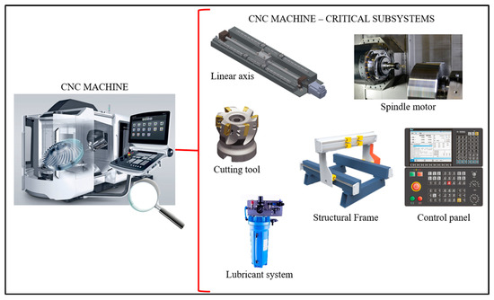
Figure 1.
Critical subsystems in CNC machines.

Table 1.
CNC machine’s critical subsystems, component breakdown, and primary functions.
The sustained operational demand on these components accelerates wear resulting in failure fault (FF) development. Ignoring an FF may result in unpredictable behavior, crashes, and prolonged periods of unplanned downtime. In the automotive sector, downtime costs have reached USD 2.0 million per hour, equating to a 50% increase since 2019 [18]. In the heavy industry sector, downtime costs have approximately quadrupled [19]. Additionally, a recent technical survey estimates that downtime costs Global 2000 companies approximately USD 400 billion annually [20].
To mitigate FFs, prevent downtime, and ensure operational longevity, manufacturers must conduct regular maintenance on their CNC machines. Traditionally, maintenance was regarded as a “necessary evil” with the belief that “nothing can be done to improve maintenance costs”, this view overlooks the true impact maintenance has on product quality, production costs, and profitability [21].
There are four principal maintenance strategies:
- Reactive: Conducted the moment a CNC component or subsystem breaks down. May incur high unplanned downtime, repair costs, and catastrophic equipment damage [22].
- Preventative: Repairing components at pre-determined time intervals, defined by the suppliers’ expert knowledge or remaining useful life (RUL) estimates [23]. Random breakdowns may still occur and component’s life is not maximized [22].
- Predictive: Data-driven assessment of component health geared towards extending operational life, reducing unnecessary maintenance, and lowering costs. However, this requires significant upfront investment and advanced technical expertise to implement effectively [24,25].
- Prescriptive: An advanced form of predictive maintenance that offers actionable recommendations but requires robust predictive systems and expert insights [25,26,27].
Maintenance costs may reach as high as USD 220 billion [28]; they are driven by three types of misdirected activities [29]:
- Unnecessary: Performing routine inspections or preventative maintenance on equipment that does not require it.
- Unproductive: Tasks such as data entry, work order reporting, and administrative paperwork that reduce working time on the machine.
- Counterproductive: Actions that inadvertently reduce equipment reliability. These may include improper reassembly, incorrect tightening, and misalignment, among other errors.
Nevertheless, adopting predictive and preventative strategies has led to a 52.7% reduction in unplanned downtime [28]. Best practice recommends a maintenance mix of 50% predictive, 25% preventative, and 25% reactive [29]. Achieving this balance requires investment in predictive technologies with condition-based monitoring (CBM) playing a key role. A CBM system typically follows four steps as showcased in Figure 2.

Figure 2.
Simplified CBM implementation framework.
The first step consists of selecting the component or subsystem to monitor, as this is crucial to determine the appropriate diagnostics tools and methods. Next, deployment of a data acquisition system to collect component health-related information. Followed by data processing and analysis to ensure data quality and extract insights. Finally, a condition report to visualize results and deliver maintenance recommendations based on component health assessment [30,31]. Figure 3 illustrates the evolution of CBM in terms of the four types of maintenance strategies.
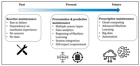
Figure 3.
CBM Evolution based on maintenance strategy.
A CBM program’s main benefit is extending the operational lifetime of a monitored component. Additionally, it can significantly reduce or potentially eliminate downtime by detecting and localizing FFs. Manufacturers that adopted a CBM system reported a 50% decrease in unplanned downtime, 55% increase in maintenance productivity, and 40% reduction in maintenance cost [18]. Despite these benefits, CBM also presents several challenges, including the following:
- Disconnection between practitioners and researchers when developing CBM systems [30].
- Endurance to the noisy nature of the manufacturing environment for robust FF detection [32].
- Under sampled, imbalanced, or erroneous datasets that may lead to inaccurate predictions and cause false alarms [33].
- Management of vast amounts of data and sensor integration in legacy machines [34].
When discussing CBM, the concept of practicality is highly dependent on industry context. In this review, a practical CBM system refers to one that balances several critical factors including ease of implementation, cost-effectiveness, system complexity, reliability, and data accessibility. A practical CBM system should integrate seamlessly without major overhaul of existing operations, provide meaningful insight without excessive technical demands, and offer measurable benefits in reducing unplanned downtime and maintenance costs. This definition frames our examination of CBM technologies, focusing on solutions that not only demonstrate technical capability but have real-world applicability for industry practitioners.
The presented review focuses on the first challenge identified by [30]. Addressing this gap emphasizes the need for CBM technologies to be practical in order for industry professionals to effectively utilize them. Thus, the following research questions (RQs) are asked:
RQ1:
How is academia, through research, addressing the practicality of designing CBM methods and technologies for the modern manufacturing industry?
RQ2:
How can industry professionals practically deploy CBM technologies in the modern manufacturing industry?
2. Methodology
2.1. The Literature Search Strategy
The comprehensive literature review presented in this article employed a three-pronged literature search strategy, as illustrated in Figure 4, to address the research questions outlined in Section 1. First, background research on the current manufacturing landscape was conducted to motivate the reader about the need for CBM. Second, the academic literature was reviewed to assess the recent advancements in CBM research. Third, the industry-focused literature was analyzed to understand practical CBM solutions available in the modern industry.
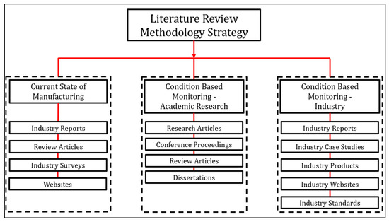
Figure 4.
The literature review methodology strategy.
A total of 150 articles including academic reviews, journal articles, dissertations, industry reports, case studies, company websites, and standards were reviewed. The literature breakdown is demonstrated in Figure 5.
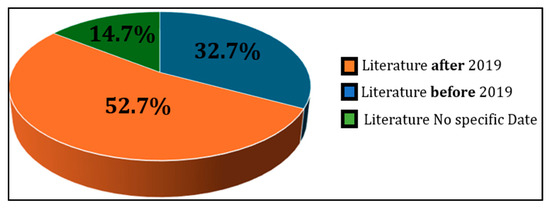
Figure 5.
Percent breakdown of the literature reviewed.
Searches were conducted across recognized databases including Scopus, Web of Science, IEEEE Xplore, ScienceDirect, and SpringerLink between January 2025 and October 2025, supplemented with targeted searches of industry reports, industry cases studies, commercial solutions, relevant standards, and technical documentation. The core search logic combined terms related to CBM technologies (e.g., “condition-based monitoring”, “sensorless monitoring”, “predictive maintenance”, “maintenance”), asset categories (e.g., “CNC machines”, “testbed”, “linear axis”, “feed drives”, “spindles”, “gears”), and analytical techniques (e.g., “vibration analysis”, “machine learning”, “time domain analysis”, “frequency domain analysis”). Moreover, most of the reviewed sources were published between 2020 and 2025. However, legacy articles from the 2000s, 2010s, and older were included for building background and motivation related to CBM, maintenance, and manufacturing.
2.2. The Literature Selection Process
The literature selection process followed a structured three-stage approach aligned with the overall review’s strategy, with each stage applying specific inclusion and exclusion criteria. A PRISMA-style process diagram summarizing the identification, screening, and inclusion is illustrated in Figure 6.
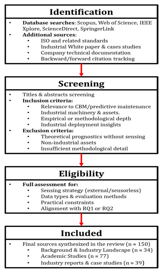
Figure 6.
PRISMA structure for review.
The literature included is as follows:
- The background literature (records reviewed = 34):
This stage focused on contextualizing the global manufacturing landscape and motivating the need for CBM in the modern industry. Sources included industry reports, surveys, journal reviews, and reputable websites. Keywords included cost of downtime, modern manufacturing, and state of manufacturing. Recent works from 2020 to 2025 were prioritized, with relevant legacy sources incorporated for historical context.
- The academic literature (records reviewed = 77):
Peer-reviewed journal articles, conference papers, and dissertations were selected for their relevance to RQ1 and the CBM framework. Keywords included linear axis, feed drives, spindle motors, gears, rolling element bearings, sensorless analysis, vibration monitoring, time domain, frequency domain, and machine learning. Emphasis was placed on studies published from 2020 to 2025 to capture recent advances.
- The industry literature (records reviewed = 39):
This stage targeted companies and organizations actively engaged in CBM. Sources include case studies, technical documentation, white papers, product specifications, and implementation reports relevant to RQ2. These materials provided insight into commercially available technologies, industrial practices, and deployment barriers.
Across all three stages, titles and abstracts were screened against relevance to either RQ1 or RQ2.
Inclusion criteria were as follows:
- Publication addressing CBM, predictive maintenance, sensor-based or sensorless monitoring, ML-based diagnostics, CNC or industrial machinery, or commercial CBM technologies.
- Studies with empirical components (testbeds, field trials, case studies) or substantial methodological details.
- Industry reports and standards relevant to real-world implementation.
Exclusion criteria were as follows:
- Works focused solely on theoretical prognostics without sensing data.
- Works addressing nonindustrial assets.
- Publications lacking methodological clarity or providing duplicate content.
In total, 150 literature works were included through this structure review process. As many industry and standards documents are not part of conventional academic indexing, sources were added iteratively through backward/forward citation tracking and expert knowledge to ensure completeness. Screening and data extraction were performed by the corresponding author.
2.3. Data Extraction and Analysis
For each included work, the following information was extracted: target asset, sensing strategy (external vs. sensorless), data types, evaluation methodology, performance indicators, practical constraints (cost, integration effort, operator burden), and key insights relevant to RQ1 or RQ2. This structured extraction and synthesis supports the objective of cross-comparison between academic and industrial approaches, highlights gaps between laboratory methods and deployable systems, and identifies practical pathways for CBM deployment.
2.4. Review Article Breakdown
The presented comprehensive review is divided into five distinct sections. Section 1 provides the reader with an introduction to the competitive nature of the modern manufacturing industry, the impact manufacturing has on a country’s economy, the importance of CNC machines and their components, the cost of downtime from the development of FFs within a CNC machine, the different types of maintenance strategies, and a CBM overview. Section 2 details the article’s literature review methodology and breakdown including key characteristics and structure. Section 3 delves into the academic research works in CBM. The literature reviewed is grouped based on the CBM framework as illustrated in Figure 2 and concludes with an overall insight into the practical CBM approach. Section 4 reviews the multiple practical solutions the industry is bringing forth to market and their impact. Finally, Section 5 concludes the literature review with concluding remarks, recommendations and future directions for CBM.
3. Condition-Based Monitoring―Academic Research
Condition-based monitoring (CBM) is an extensively researched topic to enhance equipment reliability, reduce unplanned downtime, and improve maintenance processes across the manufacturing industry. Legacy reviews emphasize CBM’s significance, frameworks, fundamental principles, and research directions.
For instance, ref. [22] highlighted CBM’s necessity over reactive and preventative maintenance strategies, defined fault types that components may experience during their operational lifetime and established foundational insights. Similarly, the review conducted by [35] emphasized CBM’s cost-effectiveness, stressing the importance of modularity and human oversight to facilitate integration across machines on the production floor. Additionally, the review by [36] underscores the traditional view towards maintenance and demonstrates an attitude shift in recent years due to its organizational strategic value to stay competitive. The review links CBM to reliability-centered maintenance (RCM), defined as a structured methodology to determine maintenance requirements of any physical asset, where its primary objective is to preserve the system’s functionality and explore techniques such as vibration monitoring, process parameter monitoring, thermography, and tribology.
CBM research continues to expand rapidly, as noted by [30] who proposed a three-step framework to implement a CBM system including data acquisition, data processing, and maintenance decision-making. The review concludes with a list of various research directions the CBM field can take, solely focusing on the improvement of technology but not its practical application. Decision-making methods were further explored in the review by [37], distinguishing between current-condition-evaluation-based (CCEB) and future-condition-prediction-based (FCPB) approaches. Each approach follows a two-step process, first assessing the equipment’s condition and, second, making a data-driven maintenance decision. It was concluded that FCPB has more benefits than CCEB due to its predictive advantages. Collectively, these legacy reviews demonstrate the growing role of CBM in ensuring equipment reliability and its acceptance across industries as the preferred approach of their maintenance operations.
3.1. CBM Research in CNC Components
As stated in [30], the traditional CBM frameworks consist of three main steps, data acquisition, data processing, and maintenance decision-making. However, with the rapid growth of CBM research, this decade-old framework requires an update. As recently discussed by [38] and shown in Figure 2 of this article, selecting the component or subsystem to monitor is a critical additional step. This choice directly affects CBM deployment practicality since efforts are more focused. The decision, as illustrated in Figure 7, should consider the criticality of the monitored component, rate of failure, and cost of repair.
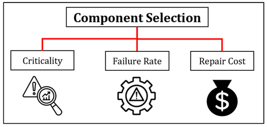
Figure 7.
Component selection decision metrics.
Researchers have also conducted studies to simplify the decision process using risk-based assessment methods such as Failure Mode Effect Analysis (FMEA). For instance, ref. [39] developed a practical methodology using Failure Mode Effect and Criticality Analysis (FMECA) for CNC lathes, identifying the spindle, linear axis, and turret as the critical subsystems of the machine based on field failure data and expert insights. Similarly, ref. [40] utilized a reliability, maintainability, and life cycle cost (LCC) analysis on a CNC turning center to identify the machine’s critical components and subsystems. Through their method and the use of time to failure and time to repair data, a 45% system reliability improvement was achieved. In the work presented by [41], fuzzy-logic-based FMEA method was proposed to identify the most serious failure modes in a CNC lathe. Moreover, ref. [42] proposed a hesitant fuzzy analytic hierarchy process (HFAHP) based on multi-criteria decision-making (MCDM) to streamline CNC router selection in the woodworking manufacturing sector. Nevertheless, subsystem-specific research is extensive and outside the scope of the presented review article. The review focused on the research articles that aimed towards the development and theorization of the practical application of CBM.
Recently interest in linear axis CBM has surged, especially regarding practical monitoring strategies. The linear axis is directly responsible for the CNC’s positioning capability that directly impacts product quality. However, access to this subsystem, particularly in legacy machines, can be challenging, raising questions about practical CBM deployment. A prevalent solution put forth by multiple researchers is the development of testbeds that simulate the operation of the linear axis. For example, ref. [38] designed a testbed with the intention to implement various types of sensors, simulate multiple FFs, and generate datasets for the research community. The practical approach on their design was to build a fully accessible testbed that enabled instrumentation of the critical components of the linear axis including the carrier blocks and linear guides. Moreover, their solution, inspired by [43], included the ability to swap components on a third rail to study the effects of FFs on the system’s operation. Similarly, in the studies by [44,45,46,47], a testbed was designed and utilized to develop their CBM methodologies and sensor system to detect the accuracy degradation of the linear axis system. The practicality came from its accessibility to various components, ability to swap components, and ability to induce FFs. Also, in the research work by [48], a testbed was designed to infuse FFs on the leadscrew component of the linear axis. The dissertation by [49] introduced a ballscrew-focused testbed that served as a foundation for digital twin development. Recent research works by [50,51] designed and experimented on a testbed to develop intelligent diagnosis for ballscrews. Once again, the practicality of their testbed is showcased in its ability to be instrumented without major space constraints. Lastly, ref. [52] designed a linear axis testbed for accelerated wear testing of the carrier blocks and linear guides to build practical insight on their progressive deterioration.
CBM research has also targeted other critical CNC subsystems, particularly motors and rolling element bearings (REBs). The Case Western Reserve University (CWRU) testbed remains a foundational and practical resource in CBM research of REBs. This testbed was designed to generate multiple datasets of varying health conditions and simulated faults [53]. Numerous global studies [54,55,56,57] utilized the CWRU datasets to design new models, methodologies, and systems. Comparatively, the work by [58] featured the design of a five-electrical-motor testbed designed to replicate four distinct machine conditions. Their objective was to practically generate a lab-scale vibration dataset and baseline methods for fault diagnosis of the most common FFs found in motors including unbalance, misalignment, and faulty REBs. Similarly, ref. [59] highlighted the practicality of a testbed in accelerating the development of CBM diagnostic methods by designing one for rotor FF detection with real-time validation.
CBM studies on gears often use testbeds for practical fault analysis and validation. In the research work presented by [60], a practical gear monitoring testbed that simplified performance analysis and monitoring of gears was proposed. Furthermore, in [61], a gearbox diagnosing framework was validated on a testbed that used industrial-grade equipment, demonstrating real-world applicability. Another institutional testbed was designed by the University of Pretoria’s Centre for Asset Integrity Management (CAIM); this testbed was featured in the research work by [62]. The objective of their research was to develop a simple CBM method for gearbox monitoring. The practicality of utilizing the testbed is illustrated through its simplicity to implement a multitude of sensors and utilize an alternator to induce time-varying speed and load conditions. Finally, ref. [63] designed a testbed that emphasized practical accessibility and fault seeding to validate their gear diagnosis method. Table 2 summarizes the insights gathered from the reviewed literature.
Table 2.
Summary of CBM research in CNC critical components.
While testbeds remain an indispensable tool for controlled experimentation and repeatability, their practicality in advancing the CBM implementation in industry is mixed. From the reviewed literature, it can be observed that they excel in providing stable environments to isolate operational variables, test multiple FF conditions, and validate emerging concepts. However, the lack of real operational variability including fluctuating loads, environmental disturbances, and complex multi-system interactions often leads to over-optimistic performance metrics that do not fully translate to the production floor. Comparatively, direct machine implementation offers higher validity but at the expense of increased downtime risk, operational disruption, and data noise. A viable research trajectory would involve hybrid methodologies that incorporate testbeds in the initial development and rapid prototyping of CBM systems, followed by progressive minimally invasive trials on live equipment to validate scalability and robustness. In conclusion, the current literature showcases a higher volume of studies reliant on testbeds, with limited documentation on the transition path toward practical industrial deployment, a gap that must be addressed for academic work to be genuinely translatable to industry.
3.2. CBM Research in Data Acquisition
Data acquisition is the next crucial phase for deploying a CBM system. This can be achieved by integrating external sensor systems, leveraging the CNC machine’s operational data, or a combination of both, as illustrated in Figure 8.
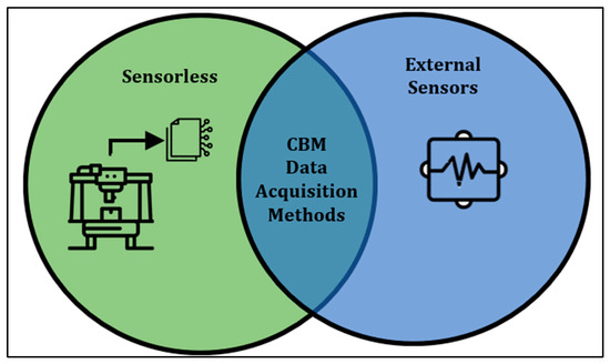
Figure 8.
CBM data acquisition methods.
At first glance, the most practical approach would be to utilize existing machine data, as it is readily available from the controller and internal sensors, avoiding additional investment on external systems.
Research in sensorless CBM has long attracted academic interest. The foundational work presented by [64] introduced a method for online vibration monitoring of induction machines. Their method assumed that the current harmonics are linearly proportional to vibration harmonics, this assumption was validated through simulation and laboratory experimentation. This study demonstrated the practicality of using the motor current harmonics as a reliable indicator of machine vibration, laying the groundwork for sensorless current-based CBM techniques. In another legacy work, ref. [65] proposed a practical method for monitoring machine health condition by analyzing motor current. The methodology consisted of employing the feed drive current parameter to predict the cutting forces and detect tool breakage in a milling machine. Similarly, the work presented by [66] proposed a novel sensorless CNC machine tool condition monitoring the method based on the open numerical control drive data. By leveraging the practically accessible by digital drive signal such as current and displacement, their method effectively detected common disturbances like backlash and pitting of guideways with reasonable accuracy. Reference [67] conducted similar research where they proposed a method that employs operational data signals including position, velocity, and motor current to develop a sensorless automated condition monitoring (SACM) system. Their method compared operational signals against baseline measurements taken when the machine was new, demonstrating that the monitoring of position signals is a practical approach to quantifying component wear in CNC systems. In the research work presented by [68], a sensorless method was proposed to estimate the positioning reversal value of a CNC’s ballscrew drive, defined as the positional difference between forward and reverse motions. By analyzing the frequency response of the feedback position and motor torque relative to command inputs, the authors demonstrate how this approach can provide practical insight to the linear axis health. Recently in the work by [69], another instance of practical CBM that employs operational data was demonstrated. The work by the authors focused in evaluating the most common root-cause FFs that affect the linear axis system of CNC machines. In one of their studies, it was demonstrated that the motor’s torque generating current can reliably distinguish between a blocked carrier block and a healthy or recently repaired carrier block. The practicality of their approach stems from the use of the operational data parameter of torque generating current and evaluating the change in a newly repaired carrier block compared to its original baseline. Additionally, the research presented by [70] proposed a sensorless anomaly detection method that uses operational data enhanced with deep weighted K-nearest neighbor (DWKNN) machine learning algorithm to monitor the health condition of the roller chain system. The methodology’s practicality lies in its use of readily available motor data, by-passing the investment on an external sensor system. In [71], the authors proposed a novel sensorless CBM method for CNC linear axis components by applying Prony analysis. Prony analysis is a parametric technique capable of decomposing short-duration signals into its spectral components unlike the conventional Fourier method. The author’s method was validated on both a testbed and conventional three-axis milling machine. Additionally, the method demonstrated its practicality by detecting artificially introduced looseness in the connecting screw without installing additional sensors. The recent work by [48] proposed a practical methodology that utilized the motor current to detect misalignment on the linear axis. The method’s effectiveness was showcased by using the readily available motor current and applying straightforward statistical and fast Fourier transform (FFT) analysis on the data. Lastly, the authors in [72] introduced a sensorless method for detecting multi-component faults in industrial robots by utilizing motor control signals including current, velocity, and operational diagnostics without additional sensors. Their approach was further enhanced with artificial neural networks (ANNs) to practically assess both component health and overall system performance.
While external sensor systems can offer valuable health insights through diverse data streams, their adoption must be carefully weighed against the practicality of installation, integration, and long-term use. For instance, in the recent work by [38], a novel framework to establish a vibration-based baseline for condition monitoring of linear axis and its components was proposed. Their testbed was outfitted with an external vibration monitoring system placed on the linear guide component. It was concluded that a baseline can be reliably established with one hour of continuous operation, there is a negligible difference when evaluating a forward and reverse stroke, and when under a known healthy condition time domain features exhibit low variability. The practicality of the approach comes from providing a standardized framework to establish a baseline that does not require massive amounts of data. In comparison, the recent work by [50] proposed a CBM system that employs inertial sensors to monitor the health condition of the linear axis’ ballscrews. To address the practical implementation of the CBM system, the authors proposed a two-phased data collection strategy: the first involves collecting data during regular operation to represent online monitoring, while the second phase temporarily interrupts operations to simulate offline monitoring. Furthermore, their CBM system consisted of various external sensors including two tri-axial accelerometers mounted directly on the ballscrew’s ball nut and an inertial measurement unit (IMU) mounted on the center of the carriage, providing a comprehensive amount of data to build insights on the health of the ballscrew. The research work conducted by [73] proposed a practical external sensor system to monitor the health condition of a CNC’s cutting tool. The authors designed a novel machine vision system to assess cutting tool life. Its practicality is demonstrated by the ease of installation on various CNC machines including lathes and mills, with minimal intrusion to the existing setup. Additionally, the vision system significantly reduced tool life studies by approximately 80%, further justifying its practical value. In a similar effort, ref. [74] introduced a practical tool condition monitoring system based on vibration analysis. Their design featured an adjustable ring compatible with tool holders ranging from 40 to 80 mm width. Additionally, vibration data is transmitted wirelessly at a low power consumption of 0.458 W, highlighting the system’s adaptability and operational efficiency. In comparison, ref. [75] highlighted the challenges of conducting spindle condition monitoring using traditional hammer tap testing, describing it as a cumbersome, time-consuming, and a technically demanding process, particularly for inexperienced users. Moreover, reliance on manual testing introduces potential for human error, underscoring its limited practicality. Therefore, the authors proposed a spring-loaded hammer tool that reliably strikes the hammer and generates similar data compared to the standard hammer tap test. Lastly, in the work by [76], a novel diagnostics method was proposed for the early identification of damage in linear axis components. The authors’ proposed method resulted in 98% reliability to identify damaged components. Moreover, the practicality of their method is showcased through its agnostic reaction to the operating conditions of the linear axis.
Although both sensorless and external sensor data acquisition approaches in CBM demonstrate practical viability, they also showcase a significant difference in implementation trade-offs. For instance, sensorless methods are considerably more attractive for their cost-effectiveness, ease of integration, and ability to leverage existing machine data without physical intrusion, attributes that are particularly valuable when retrofitting legacy systems. However, they are heavily dependent on the fidelity and accessibility of internal signals which vary based on the OEM and control architecture. Conversely, external sensors offer measurement independence, richer data, and the flexibility to detect faults invisible to internal metrics, but at the cost of installation complexity, calibration requirement, and environmental susceptibility. The most practical solutions in the literature tend to integrate both, yielding sensorless methods for continuous low-cost monitoring, augmented by targeted external sensors for higher diagnostics and potentially prognostic resolution. In conclusion, the lack of standardized performance benchmarks and comparative validation between these two approaches remains as a gap to broader industrial adoption. Addressing this gap will require hybrid frameworks that balance diagnostics capability and relate to operational efficiency and economic benefit. Table 3 outlines the insights from sensorless and external sensor data acquisition techniques and Table 4 provides the various characteristics from the external sensors used in the reviewed literature works.
Table 3.
Summary of CBM research in data acquisition.
Table 4.
External sensor performance attributes.
3.3. CBM Research in Data Analysis
Data analysis and signal processing is the next phase of deploying a CBM system and may be broken down as Figure 9 illustrates.
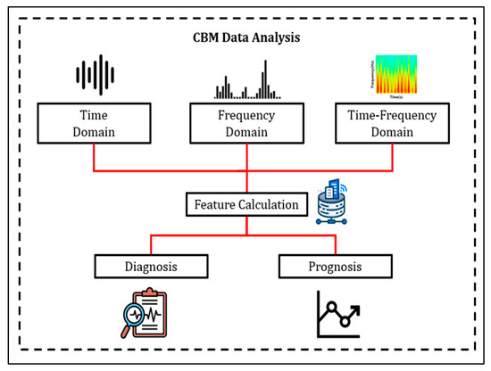
Figure 9.
CBM data analysis breakdown.
Research in this area alone is extensive, ranging from a multitude of analytics methodologies to pre- and post-processing techniques for more reliable machine health assessments. However, the practical applicability of these solutions remains a key consideration. In CBM the most prevalent analysis methods include time domain, frequency domain, and time–frequency domain analysis.
Firstly, time domain analysis practicality stems from being the simplest analytics method in a CBM system. This method contains abundant component fault information due to the deviation from a nominal established threshold of calculated features as operation continues [23]. Apart from its simplicity, time domain analysis struggles with obtaining specific component fault details and there are no proper guidelines on feature selection [38].
Frequency domain is another commonly utilized analytics method in CBM programs. This approach helps in identifying frequency components present in the collected signal and their respective amplitudes. Thus, making it a practical approach for fault detection in rotating machinery [77]. Unfortunately, frequency domain analysis also presents drawbacks such as the inability to efficiently analyze transient features, carrying a risk of misdiagnosis if misinterpreted, and often demanding specialized expertise due to its complexity [78].
Lastly, time–frequency analysis is an advanced signal processing method that combines the two previously discussed analytic approaches’ strengths. Non-stationary signals that vary with time can be properly handled using this approach. Its practicality is illustrated by the capability to quantify the time-varying phenomenon in the frequency content of the evaluated signal [78,79]
Nevertheless, the common theme between all these types of analysis methods revolves around the calculation and use of features to diagnose and/or prognose the health status of the monitored machine, system, or component. Legacy works, such as the one from [80], aimed at providing the reader with a practical guide for diagnostic analysis of acceleration signals from REBs. The tutorial delves into how to interpret the vibration signals in both the time and frequency domains. Similarly, ref. [81] provided a comprehensive and practical understanding of how vibration signals change in linear axis components. Another instance of practical CBM is showcased by [32], where the collected operational data such as drive current, axis position, and feed rate is analyzed using time domain methods to detect evolving deterioration patterns. More recently, the comprehensive tutorial conducted by [82], expertly described the steps to practically conduct time domain and frequency domain analysis and interpret the results for gears and REBs. The tutorial’s practicality focuses on aiding CBM beginners with the foundational basic concepts and how to implement CBM algorithms utilizing the MATLAB software environment. Furthermore, in the comprehensive review by [78], the authors discussed the practicality and usefulness of the three-domain analysis. A deep dive into how to extract features in each of these domains, apply their respective mathematical formulas, and interpret the results was provided. It was showcased that root mean square (RMS), FFT, and wavelet transform (WT) are commonly used methods for each of the three-domain analyses, respectively. In the work by [83], a practical novel signal processing technique was proposed to detect misalignment. Their proposed method consisted of segmenting the collected vibration signature and conducting time domain analysis. It was demonstrated that segmenting the signal increased the usability of time domain analysis features, such as RMS, by double. Another instance of signal processing is observed in the work by [84], the authors presented an automatic time-series segmentation to divide a machine processing signal into semantically related sections. The practicality of their approach is showcased in the identification and visualization of the various machine operations that may aid users in focusing their data analysis. Another instance of practical data analysis for CBM can be observed in the recent work by [69]. The authors introduced a repair state analysis on the components and compared the difference with the baseline when a repair process was conducted. In [85], the authors developed a dynamic health index extraction method for bearing degradation detection. Its practicality lies in fusing individual features into a comprehensive health index, effectively suppressing non-stationary and noise issues. Additionally, their method was tested in real case studies to showcase its robustness. Another example of practical CBM model development can be observed in the work by [86]. The authors proposed a CBM test cycle designed to capture reproducible data. Moreover, to validate its practical applicability, they tested their method on a complex testbench that resembled a milling CNC machine. Revealing that axis position, temperature, and assembly variance are critical factors of disturbance affecting linear axis performance. Reference [87] presented a practical machine health indicator construction framework that fused commonly used CBM features in all three domains into a single explainable health indicator. To test the framework’s validity, a multitude of case studies were conducted including battery health assessment, point machine CBM, and gearbox CBM.
Data analysis can be taken a step further by utilizing features for FF diagnosis to prognose the development of FFs and calculate the monitored component’s RUL. Nevertheless, one must still ask how practical these methods are. For instance, the work by [88] proposed a prognostics CBM method to find the optimal maintenance decision with maximum net revenue for systems with multiple components. The practical benefit of their proposed method is the sensitivity analysis extension to include the economic effects of the model’s prognosis. Another practical demonstration of a prognostic’s method is proposed by [89]. The recent work by the authors aimed to acquire early and reliable RUL prediction of REBs by combining an envelope spectral indicator and extended Kalman filter, resulting in highly accurate RUL, even at early stages of damage. Comparatively, the prognostics approach proposed by [90] focused on constructing a health indicator from multiple data sources to accurately quantify the monotonicity of a signal in the presence of noise. Thus resulting in a successful prediction of REB run-to-failure data for two separate case studies. Furthermore, ref. [91] proposed a health indicator construction method that employs principal component analysis (PCA) to fuse multiple features. Their method’s main goal was to calculate the RUL of wind turbine gearboxes and resulted in a 2.73% prediction error. Most recently, ref. [92] proposed a practical prognostics method that utilized the transmission error as an indicator to assess fatigue severity and RUL prediction for the gearbox subsystem. Their novel indicator resulted in an R-squared value of 0.9420 and low RUL prediction absolute errors for multiple running speeds. Another instance of practical CBM RUL prognostic calculation was proposed by [93]. The authors developed an RUL prediction method for ballscrews using weighted Mahalanobis distance enhanced with an exponential model to describe the degradation path. Their approach demonstrated superior accuracy, yielding the lowest prediction error compared to both linear and nonlinear models, highlighting its practical reliability. Similarly, the research work presented by [94] proposed an RUL estimation method for ballscrews, that consisted of applying probabilistic classification models to monitor the deteriorating preload condition. Also, in the work by [95], an RUL prediction framework for ballscrews was proposed. Their framework’s practicality stems from leveraging physical and data-driven methods to reveal the ballscrew’s backlash degradation, resulting in highly accurate predictions. Another example of RUL modeling is presented by [96], where the authors proposed a novel multi-sensor fusion method to predict cutting tool life. The practicality of their approach can be observed in its ability to be analogous to the effect of variable working conditions of the machining process. Finally, the recent work presented by [97] proposed a novel RUL method that addresses the multiple degradation modes REBs face during their operational lifetime. In their method the authors fuse features from all three data analysis domains to construct a health indicator. When compared to commonly used prediction methods, theirs reduces the mean absolute relative error by 58.72% and is adaptable even under the self-healing condition of REBs.
Practicality in data analysis is often confused with simplicity, yet the two are not synonymous. Simple methods, such as RMS vibration or basic frequency domain features, are indeed practical when they reliably capture relevant FF signatures under real operating conditions. However, oversimplification risks masking early-stage FF development or generating false positives, eroding the trust in the CBM system. Conversely, advanced techniques such as wavelet decomposition, high-order spectra, or hybrid time–frequency methods offer richer diagnostic insight but introduce computational overhead and human expert requirements that can hinder industrial implementation. The literature suggests that a tiered approach is a practical path forward where established lightweight data analysis is used for continuous monitoring and more complex analytics are deployed on a case-by-case basis for confirming anomalies. This layered structure balances the need for speed, interpretability, and depth, aligning academic capabilities with industrial operational realities. Table 5 summarizes the findings from the conducted literature review for both types of analytic techniques.
Table 5.
Summary of CBM research in data analysis.
3.4. CBM Research in Machine Learning Applications
Research in the CBM field has increasingly focused on leveraging machine learning (ML) methods to enhance diagnostics and prognostics. Comprehensive reviews on machine learning alone are widely available, some are referenced for the readers interest [9,78,98,99,100,101]. RQ1 still lingers, especially when looking at the practicality to deploy an ML model for CBM maintenance. For instance, the legacy work by [102] introduced the use of ANN for FF diagnosis of REBs. The practicality of the research work was showcased by utilizing simple time domain features to build their model, resulting in approximately 100% success. The research work conducted by [103] proposed an ANN ML model to detect FFs in Auto Core Adhesion Mounting machines used in the electronics manufacturing sector. Their proposed model showcased its practicality in its design by utilizing a fusion of simple parameters including the FFT spectrum, motor current, and crest factor, resulting in a prediction accuracy of 93%. Moreover, the authors in [63] highlighted the complexity and limitations of traditional signal processing and feature extraction methods for gear FF diagnostics. To address this gap, they developed a convolutional neural network (CNN) model enhanced with signal segmentation, enabling focused analysis on individual gear teeth. Ultimately, their approach resulted in 99% accuracy for detecting artificial FFs, showcasing its effectiveness and practicality. More recently, ref. [104] proposed the use of a variational auto encoder (VAE) ML algorithm trained on normal linear axis data to detect FF development. The reconstruction error of the proposed model was used as a practical metric to measure its detection performance that resulted in more than 90% accuracy. Similarly, ref. [105] applied various ML algorithms for robotic arms’ health assessment in grinding operations. Among the tested models, Decision Tree (DT) and Random Forest (RF) algorithms yielded the highest accuracy. Also, the study offered valuable insights regarding the practicality of implementing ML techniques to enhance the reliability and operational efficiency in manufacturing environments. A different approach was presented by [106], where Generative ML was used to synthesize realistic data. The practicality of their approach lies in replacing costly experimental data collection with synthetic datasets, which were shown to be equally effective for training diagnostic algorithms. In another instance, ref. [107] focused on the open issue regarding the interpretation of diagnostic outcomes from ML algorithms. The authors employed Shapley additive explanation (SHAP) to identify the most critical features in FF detection and classification. Ultimately, their model enhanced the support vector machine (SVM) and K-nearest neighbor (KNN) ML algorithms by achieving diagnostic accuracies higher than 98.5%. Furthermore, SHAP values provide a practical interpretation of ML algorithms for industrial settings. Comparatively, ref. [108] developed a deep learning strategy that is agnostic of varying operational speeds. The authors justified that machines constantly operate at various speeds, and it is impractical to conduct CBM on a fixed set of operating conditions. Overall, their results showcased how Long Short-Term Memory (LSTM) and CNN deep learning methods performed under varying speed conditions. Reference [61] proposed a gearbox CBM method that utilizes Reduced LaGrange Method (RLM) to assign pseudo labels to unlabeled datasets, decreasing the false alarms and practically explaining which features were responsible for equipment variation. The novel work presented by [109] consisted of implementing a practical real-time monitoring system that combines multiple data streams including vibration, temperature, humidity, and operating temperatures to measure the process caliber of the CNC machine. Their method trained an ML model through linear regression utilizing the FFT data, resulting in a 97.5% accuracy detection rate. The authors in [110] designed a LeNet deep convolutional neural network (DCNN) model to detect misalignment on the linear axis. The practicality of their proposed method stems from its sensorless design, where the model was trained solely on current data retrieved from the machine’s programmable logic controller (PLC). Overall, their model achieved a misalignment detection accuracy of 96.43%.
Throughout the reviewed literature, ML methods have demonstrated high diagnostic and prognostic accuracy. However, industrial deployment remains constrained by interpretability, data scarcity, and generalization challenges across varying operating conditions and machine systems. Comparatively, manual analysis, though limited in scalability, offers transparency and incorporates operator domain expertise, qualities often absent from black-box ML models. The most promising trend in the literature lies in explainable AI techniques, such as SHAP value analysis, hybrid physics-informed ML, and feature importance ranking, that bridge the gap between automation and human trust. Practical deployment will likely depend on hybrid workflows, where ML models automate FF detection and preliminary classification, and human experts validate and contextualize findings. Furthermore, future ML research works would benefit from more structured and transparent model design choices, data inputs, and evaluation procedures, as this clarity supports practical interpretation and comparison of results. Ultimately, this integration ensures efficiency while preserving the interpretability necessary for safety-critical industrial environments. Table 6 summarizes the reviewed literature works’ various parameters considered for their ML model training and their respective success.
Table 6.
Summary of parameters used in ML methods.
3.5. Overall Practical Approach to CBM
The comparative insights across Section 3.1, Section 3.2, Section 3.3 and Section 3.4 converge on a central conclusion where practicality in CBM is defined not by novelty of individual methods but by their deployability, adaptability, and sustainability in industrial operational environments. The most viable CBM strategies are inherently hybrid, combining lab-grade testbed validation with live machine trials, integrating sensorless and external sensing, adopting tiered analytical workflows, and blending automated ML with human oversight.
To synthesize the academic literature through a deployment-oriented lens, a CBM practicality scorecard was developed. The scorecard evaluates CBM approaches using five criteria that directly influence their real-world applicability.
The scorecard criteria are described as follows:
- Integration and installation effort: ease of mounting, commissioning, and interfacing.
- Cost of implementation: approximate cost of hardware, software, licensing, and ongoing support or maintenance effort.
- Skills and operational experience required: the level of specialist analytical, ML, or vendor-dependent expertise needed to operate and maintain the solution.
- Data accessibility and rights management: availability of required data from controllers, drives, sensors, or cloud platforms without prohibitive vendor or contractual barriers.
- Maintainability and standards alignment: compatibility with relevant ISO standards and the ease with which the solution can be sustained and updated over time.
Each criterion is scored on a simple 0–3 practicality scale (0 = low practicality, 3 = high practicality). The goal of Table 7 is not to exhaustively evaluate all reviewed studies, but to illustrate to the reader the typical practicality profiles using a small representative set of academic identified trends from Section 3.1, Section 3.2, Section 3.3 and Section 3.4.
Table 7.
Illustrative CBM practicality scorecard for representative academic approaches.
The examples highlighted in Table 7 showcase an interesting trend: testbed-based and algorithmically intensive methods often score lower in cost, skills required, and practicality due to the highly specialized expertise needed and the freedom to continuously add more systems. Comparatively, methods that are applied to production machines score lower in data accessibility, maintainability, and integration effort.
Additionally, economic considerations also play a central role in the practicality of CBM implementation. While cost-benefit evaluation is an essential step in implementation of any system in industry. Practitioners should be aware that the financial impact of CBM is highly dependent on multiple factors including machine type, production environment, sensing strategy, labor rates, and OEM-specific data access constraints. As a result, economic justification is best approached through structured prioritization methods rather than universal cost estimates.
Future academic work should not only develop algorithms and sensor systems but also explicitly map the transition from lab-scale ventures to industry, incorporating cost-benefit analysis, operator training, and system maintainability. In addition, greater consistency in how studies report operating conditions, FF scenarios, and evaluation metrics would help establish a more comparable benchmark between different CBM approaches. Embedding these deployment and reporting pathways into research practice will enable CBM solutions to achieve the level of robustness and trust required for widespread industrial adoption.
4. Condition-Based Monitoring―Industry
4.1. CBM in Industry
Companies that operate in the predictive maintenance and CBM space typically offer products and services in one or more of the following categories:
- Software platforms
- Sensor systems and hardware
- Consulting services
- Education
Table 8 summarizes the various industries that were reviewed for the article and what their products and services fall under.
Table 8.
Reviewed companies and the products and services offered.
Siemens (Munich, Germany), the German-founded multinational technology conglomerate, offers analytics and AI Services to support CBM implementation. Their software system “Senseye” enables asset intelligence across multiple plants, voids manual data analysis, promotes machine availability, directs maintenance activities, enables knowledge, and ensures operational sustainability [111]. Mercer Celgar (Castlegar, BC, Canada), one of the largest pulp and solid wood product producers, implemented Senseye Predictive Maintenance technology after their machine monitoring service was discontinued. The implementation effort centralized data streams and enhanced machine monitoring capabilities across all assets [112].
Similarly, Bosch (Gerlingen-Schillerhöhe, Germany) developed a software platform, NEEXED, to push forward digitalization and bring a practical solution for connecting machines and departments. Its “Machine & Equipment” module provides a comprehensive picture of current machine health status and facilitates short-term decision-making in the event of error or malfunctions through data centralization [113,114].
Fuji Automatic Numerical Control (FANUC) (Oshino, Japan), founded in Japan in 1972, is a global leader of CNC systems, robotics, and ROBOMACHINES. FANUC recognized the true cost of unexpected downtime and maintenance to make machines operational once again. Therefore, the company developed a “Zero Downtime” (ZDT) software system solution to prevent unplanned outages through real-time condition monitoring, status tracking, and automated alerts. As of 2023, ZDT is deployed in over 35,000 robots worldwide and prevented over 1700 cases of unplanned downtime [115,116]. Additionally, FANUC launched the MT-LINKi software platform for machine tool monitoring, capable of monitoring up to 2000 machines at a time. The software platform connects via PC and Ethernet, offering a quick plug-and-play setup. Also, it provides the user access to operation and production data, enabling performance monitoring, diagnostics, and productivity optimization through streamlined connectivity [117,118].
Moreover, the robot manufacturers KUKA (Augsburg, Germany) and ABB (Zurich, Switzerland) developed CBM software platforms to monitor the health condition of their deployed industrial robot assets. For instance, KUKA developed the exclusive platform iiQoT. A software platform designed for industries to be able to monitor, track, and visualize the condition data of their robot fleets via four core functions including asset management, changelog, notification, and IT security. Additionally, the platform’s modular architecture enables users to have practical customization based on their plant requirements and a direct line to KUKA technicians for troubleshooting [119]. Comparatively, ABB provides data-driven services including “Condition-Based Maintenance” and “Connected Services” platforms for secured uptime and optimized performance of its robot assets. ABB’s “Condition-Based Maintenance” platform offers its users with the ability to rapidly find robot assets undergoing high operational stress. Moreover, the platform offers a two-tier analysis approach where Level 1 provides a fleet-wide overview of highly stressed robots, and Level 2 delivers in-depth diagnostics and tailored preventative maintenance recommendations [120]. In contrast, “Connected Services” integrate condition monitoring, diagnostics, back-up management, remote access, fleet assessment, and asset optimization in a single software platform. Its key features including trend analytics, controller measurements, real-time alarms, and actionable dashboards, aiming to streamline maintenance by accelerating response times and improving failure detection [121].
Gastops (Ottawa, ON, Canada), a Canadian company established in 1979, specializes in real-time prognostics powered through human ingenuity and machine intelligence to deliver optimal equipment performance across the aerospace, energy, and defense sectors. Their mission is to increase productivity and safety of mission critical equipment for operators, maintainers, and original equipment manufacturers (OEM) at a global scale [122]. Their two flagship solutions, MetalSCAN and ChipCheck, respectively, use physics-informed monitoring to detect faults in vital components. For instance, MetalSCAN is an online full-flow oil debris monitoring system that collects and processes real-time data of oil-lubricated components to give early warning indication of abnormal wear and RUL prediction. The practicality of MetalSCAN is in its ability to be implemented as part of the monitored system without any major design overhaul. Also, it has a wide range of military and commercial applications with its debut in the F22-Raptor fighter aircraft [123]. To showcase its detection reliability, a case study was conducted where MetalSCAN detected premature wear in a GE LM6000 Aerodrive Gas Turbine bearing, 44 days before failure. Ultimately avoiding 96 h of unplanned outage, outperforming vibration, temperature, or chip detection [124]. Finally, ChipCheck is another of Gastops’ main products that empowers users to make fast maintenance decisions through an on-site chip analysis that is quick, reliable, and conclusive [125].
Erbessd Instruments (Glens Falls, NY, USA) is another example of a globally recognized sensor-based company operating in the CBM space with over 40 years of experience. Their mission revolves around simplifying and improving customer experience toward deploying vibration monitoring systems. Erbessd’s primary focus is the development of vibration and condition monitoring technology for industrial equipment. Their products include various types of vibration sensors, condition monitoring software, and motor balancing machines. When focusing more on the sensors market, Erbessd’s practical approach was to develop small wireless sensor systems for easy installation, convenience, low costs, accessibility, and security [126,127]. For instance, their Phantom 3 vibration sensor was utilized in a case study to determine the root cause of mechanical failure in a pelletizing machine [128]. The machine consistently experienced premature breakage in its connection joint between the motor and drive. After thorough investigation, bearing failure of the motor was ruled out since no obvious pattern was noticeable. However, random impacts affecting the drive shaft were detected due to momentary material blockage. Therefore, the following two recommendations were made:
- Improvement of the material flow to prevent blockage;
- Revision and potential redesign of the coupling mechanism to withstand the forces generated by the blockage.
In another case study [129], the Erbessd Phantom 3 vibration sensor was deployed to diagnose the health condition of a turbogenerator. The monitored unit had multiple reports of significant vibration level increases during load operation, especially in the early morning shifts (5:00–9:00 a.m.). An initial exploratory analysis was conducted and revealed residual unbalance of turbine and generator motors, misalignment between components, and possible looseness in the bearings. Therefore, based on the results, full instrumentation of the generator with wireless Phantom 3 sensors was conducted. During routine monitoring, analysis of the vibration spectra demonstrated that the increase in vibration was attributed to changes in the lubrication oil temperature, causing oil whirl/whip in the bearings. Corrective action on the equipment was taken based on the data-driven findings and no further vibration amplitude increases were detected. Moreover, the following recommendations were provided to ensure nominal operation of the generator:
- Installation of an oil temperature control system;
- Revision of bearing geometries to identify potential gaps and minimize oil whirl.
Waites (Cincinnati, OH, USA) is another example of a sensor- and software-based company with over 500,000+ sensors deployed worldwide. Their vibration monitoring solution combines wireless plug-and-play sensors with an intuitive software platform that can start monitoring machine health in under 5 min. Additionally, their software solution connects field maintenance associates with Waites analysts for real-time diagnosis [130,131]. A case study from the iron ore mining industry was conducted to showcase the capabilities of the Waites sensor system. The vibration sensor system was able to identify periodic impacts at the running speed and traced them to a loose bolt at the drive end of a screen exciter. Thus, allowing the maintenance team to intervene before catastrophic failure occurred and mitigate the detected fault [132]. Similarly, Fluke (Everett, WA, USA) is another provider of both sensor and software solutions for vibration monitoring of machine assets. The Fluke 3503 vibration monitoring system practicality comes from its simple deployment capability, wireless sensor technology, and intuitive software platform [133].
Falkonry (Cupertino, CA, USA) is an example of a purely software-based company in the CBM space. Their solution streamlines data streams from various sources, including IOT sensors, Historian data, SCADA, MES and PLCs, into a purpose-built AI to enable smart decisions and precise maintenance actions. Falkonry has enabled CBM actions across a multitude of industries such as metals, defense, semiconductors, oil and gas, automotive, and pharma [134,135]. A short case study conducted in the pharmaceutical operations market identified that some processes, such as rubber vulcanization, are difficult to control and may result in production losses and unexpected equipment downtime. Falkonry’s time-series AI identified patterns indicative of abnormal behavior deviations, enabling process engineering teams to act 8 h before quality issues began and guide maintenance engineers to adjust the equipment accordingly. These data-driven actions helped achieve a 10% capacity increase and reduce production-loss costs by USD 1 million [136]. In the oil and gas industry, Falkonry’s software demonstrated its practical value by predicting compressor failures. With unscheduled outages typically causing 36 h production losses and approximately USD 300,000 per failure incident. Falkonry’s AI identified early fault patterns, allowing the client to detect failure six weeks in advance using existing data [137].
Companies were also founded to act as consultants and provide educational content regarding CBM and machine diagnostics. For instance, the Mobius Institute North America (MINA) has operated in the CBM market space for more than 25 years by providing public courses, on-site training, and web-based education. MINA certifies professionals in vibration analysis, lubrication, thermography, and ultrasound. Moreover, MINA guides industries through their Maintenance and Reliability Transformation (MRT) 12-step process to break away from reactive maintenance. Their practical approach identifies critical equipment, eliminates wasteful tasks, improves maintenance activities, and monitors equipment health all while working alongside their client’s personnel [138,139].
4.2. Standards for CBM Implementation
To streamline the practical implementation of CBM systems, various standards were drafted, each focusing on the different implementation blocks of the CBM framework as previously illustrated in Figure 2. For instance, ISO 13372 [140] provides the basic terminology and vocabulary in the field of CBM and machine diagnostics. This standard enables industry professionals to communicate more effectively when implementing and working with CBM systems [140]. Comparatively, ISO 17359 [141] provides professionals with guidelines and a general implementation procedure flowchart, outlining the key steps to practically design a CBM system. Additionally, the standard focuses on a cost-benefit analysis and equipment audit to justify the deployment of the CBM program [141]. In terms of metrics to assess the health of the machine or subsystem being monitored, ISO 230-1 and ISO 20816-1 are critical standards that CBM practitioners should be familiar with [142,143]. In ISO 230-1, methods for testing machine tool accuracy under no load or quasi-static conditions are specified, these can be utilized to define the overall health of the measured system or subsystem [143]. In comparison, ISO 20816-1 was drafted to establish basic guidelines to measure and evaluate the mechanical vibrations in machinery. The standard includes graphical representation of the maximum vibration a machine of a particular size may exhibit during operation. Additionally, it is divided into nine distinct parts that delve into machine components including gears, turbines, pumps, and compressors, among others [142]. Regarding the implementation of sensors, especially for a vibration monitoring CBM program, ISO 5348 [144] outlines the importance behind the mechanical mounting of accelerometers. The standard’s main purpose is to guide the user in understanding the mounting limitations alongside the potential measurement deviations from accelerometers. The standard further explores the technical properties of the different mounting techniques and outlines recommended practices [144]. Finally, the ISO standards 13373-1 and 13374-1 are focused on condition monitoring and diagnostics of machines as a whole [145,146]. For instance, the scope of ISO 13373-1 is centered around measurement consistency by providing recommendations and general guidelines for acquiring and evaluating vibration data from machines and their components. Overall, the standard is a perfect guide for beginner and experienced CBM specialists, since it encompasses all aspects of the CBM framework as illustrated in Figure 2 [145]. Additionally, ISO 13374’s main intent is to provide basic software specifications and requirements for machine data processing, communication, and display without an open-software schema. The standard provides readers with a comprehensive flowchart of the various data processing and information blocks that encompass a CBM system. Moreover, the standard illustrates examples of how data may be displayed based on the application. It utilizes a schema divided into five distinct areas including state detection, health assessment, prognosis, recommended actions, and identification. The standard is useful for CBM specialists with software backgrounds looking into developing software applications and data processing algorithms for CBM systems [146]. Lastly, ISO 13379 offers readers general guidelines for data interpretation and diagnostic techniques to determine the health condition of an evaluated machine, enhanced with procedures to identify the cause(s) of the anomalous behavior [147]. Figure 10 provides a high-level visual alignment between the CBM framework and the reviewed ISO standards that support each implementation block.
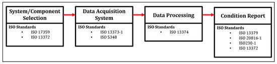
Figure 10.
High-level alignment between CBM framework and ISO standards [140,141,142,143,144,145,146,147].
The reviewed standards demonstrate that to practically apply these technologies standardized methods and guidelines are necessary to ensure robust CBM systems are deployed in both academia and industry. As an example, the legacy research work presented by [148] utilized the ISO 10816 (now 20816) standard to develop their methodology for practically establishing a robust baseline dataset for CNC monitored components. Similarly, the research conducted by [149], utilized ISO 13373, 13374, and 20816 as guidelines to develop their assessment methodology of the functional condition of equipment in industrial plants. Lastly, ref. [150] applied the guidelines from ISO 13379 for data analysis and interpretation and ISO 13374 for software development for their CBM framework.
In summary, the implementation of CBM systems in industry hinges on balancing technical capabilities with real-world practicality. As demonstrated, companies address this through integrated software solutions, plug-and-play sensors, comprehensive training, and adherence to established standards. These collective efforts ensure that CBM solutions meet industry demands for reliability, cost-effectiveness, and ease of deployment. Thus supporting the practical adoption of CBM in modern manufacturing and addressing RQ2 of this review.
5. Conclusions and Future Directions
5.1. Conclusions
Modern manufacturing is a fiercely competitive and demanding industry globally, where efficiency and uptime are critical. To meet rising production demand, CNC machines are pushed faster and harder, accelerating the wear of critical components and subsystems. Thus causing unexpected failures, costly downtime, and lost productivity. Implementing a CBM system to monitor the health condition of CNC assets and proactively detect failures is vital to maintain a competitive edge.
Over the past decade, both academic research and industrial development in CBM technology have grown exponentially due to its multitude of benefits. This review sets out to examine how practical these advancements are when applied in modern industrial contexts, assessing both research contributions and industry-driven solutions.
From the academic perspective, the following conclusions were made:
- Efforts on testbed development for critical CNC subsystems allowed for controlled experimentation, fault simulation, and vast dataset generation without disrupting production. However, knowledge transfer to real-world production environment remains limited.
- Both sensorless and external sensor data acquisition methods continue to evolve. Sensorless approaches offer cost effective, machine-integrated solutions. Comparatively, wireless external sensor systems are gaining traction for their ease of deployment.
- Data analysis techniques, including advanced signal processing, are improving CBM reliability by enhancing data quality and actionable insights.
- The rise of ML models aims to improve fault detection accuracy and provide practical health assessments of machine assets.
From the reviewed industry-driven solutions, the following conclusions were made:
- The economic impact of downtime is driving industries to heavily invest in CBM solutions for reliable asset operation and proactive maintenance.
- Market trends show a shift towards software-centric CBM platforms, often bundled with subscription-based support services.
- Industry-led education and certification programs are emerging as key tools for equip maintenance professionals with essential CBM skills.
- ISO standards are increasingly recognized as essential frameworks for CBM implementation.
5.2. Future Directions
To bridge the gap between academia and industry, the following future directions are identified:
- Focus on the development of plug-and-play CBM systems that require minimal setup and integration.
- Researchers should prioritize real-world testing of their models across diverse industrial environments, with support from industry partners.
- Academic institutions should expand training initiatives to prepare industry professionals for CBM deployment.
- Both academia and industry should consistently align with ISO guidelines to promote standardized CBM practices.
- Strengthen the collaboration between academia and industry to ensure CBM research addresses practical challenges and fosters technology innovation.
5.3. Recommendations
The following recommendations are proposed to guide academic researchers and industry practitioners:
For academia,
- Develop and maintain publicly available datasets of critical machine components, enabling industry practitioners to analyze and understand component behavior under controlled environments.
- Emphasize studies that target multi-component systems and real-world industrial scenarios.
- Increase collaboration with industry at the component and operational level to conduct and validate studies focused on practical implementation.
- Align research methodologies with existing ISO standards to enhance applicability and adoption.
For industry,
- Utilize academic datasets and findings to inform internal CBM strategies and training.
- Prioritize CBM solutions that are modular and scalable with operations.
- Adopt ISO standards as a foundation for CBM program design and deployment.
- Foster partnerships with academic institutions to accelerate technology transfer and innovation.
Author Contributions
Conceptualization, A.H.C.; methodology, A.H.C.; investigation, A.H.C.; resources, S.C.V.; writing—original draft preparation, A.H.C.; writing—review and editing, A.H.C.; visualization, A.H.C.; supervision, S.C.V.; project administration, S.C.V.; funding acquisition, S.C.V. All authors have read and agreed to the published version of the manuscript.
Funding
This research was supported by the Natural Sciences and Engineering Research Council of Canada (NSERC) under their Discovery Research Grant Program RGPIN-2019-07096.
Data Availability Statement
No new data were created or analyzed in this study. Data sharing is not applicable to this article.
Conflicts of Interest
The authors have no competing interests to declare that are relevant to the content of this article.
Abbreviations
The following abbreviations are used in this manuscript:
| CBM | Condition-based monitoring |
| USA | United States of America |
| CNC | Computer Numerical Control |
| HMI | Human machine interface |
| FF(s) | Failure fault(s) |
| RUL | Remaining useful life |
| IEEE | Institute of Electrical and Electronics Engineers Xplore |
| RCM | Reliability-centered maintenance |
| CCEB | Current-condition-evaluation-based |
| FCPB | Future-condition-prediction-based |
| FMEA | Failure Mode Effect Analysis |
| FMECA | Failure Mode Effect and Criticality Analysis |
| LCC | Life cycle cost |
| HFAHP | Hesitant fuzzy analytic hierarchy process |
| MCDM | Multi-criteria decision-making |
| REB | Rolling Element Bearing |
| CWRU | Case Western Reserve University |
| CAIM | Centre for Asset Integrity Management |
| SACM | Sensorless automated condition monitoring |
| DWKNN | Deep weighted K-nearest neighbor |
| FFT | Fast Fourier transform |
| ANN | Artificial neural network |
| IMU | Inertial measurement unit |
| RMS | Root mean square |
| WT | Wavelet transform |
| PCA | Principal component analysis |
| ML | Machine learning |
| CNN | Convolutional neural network |
| VAE | Variational auto encoder |
| DT | Decision Tree |
| RF | Random Forest |
| SHAP | Shapley additive explanation |
| SVM | Support vector machine |
| KNN | K-nearest neighbor |
| LSTM | Long Short-Term Memory |
| RLM | Reduced LaGrange Method |
| DCNN | Deep convolution neural network |
| PLC | Programmable logic controller |
| FANUC | Fuji Automatic Numerical Control |
| ZDT | Zero Downtime |
| OEM | Original equipment manufacturer |
| MINA | Mobius Institute North America |
| MRT | Maintenance and Reliability Transformation |
References
- Canadian Manufacturers & Exporters (CME). Manufacturing a Competitive Business Environment in Canada. 2017. Available online: https://cme-mec.ca/wp-content/uploads/2018/11/Doc_Industrie-2030_Manufacturing-a-Competitive-Business-Environment-in-Canada.pdf (accessed on 10 February 2025).
- Canadian Manufacturers & Exporters (CME). Manufacturing Ontario’s Future Leveraging an Advanced Manufacturing Strategy for Growth and Prosperity. February 2024. Available online: https://cme-mec.ca/wp-content/uploads/2024/01/Manufacturing-Ontarios-Future.pdf (accessed on 10 February 2025).
- Safeguard Global. Top 10 Manufacturing Countries in the World in 2024. Available online: https://www.safeguardglobal.com/resources/blog/top-10-manufacturing-countries-in-the-world/ (accessed on 20 April 2025).
- Avella, L.; Fernández, E.; Vázquez, C.J. Analysis of manufacturing strategy as an explanatory factor of competitiveness in the large Spanish industrial firm. Int. J. Prod. Econ. 2001, 72, 139–157. [Google Scholar] [CrossRef]
- Dou, Z.; Wu, B.; Sun, Y.; Wang, T. The Competitiveness of Manufacturing and Its Driving Factors: A Case Study of G20 Participating Countries. Sustainability 2021, 13, 1143. [Google Scholar] [CrossRef]
- Venkatesh, M.; Krishnan, N. The Role of CNC Machines in Modern Industrial Automation. Int. J. Adv. Sci. Res. 2024, 4, 1–8. [Google Scholar]
- Madan, A.K.; Khanduri, A.; Nagdewani, R. CNC Machines—Case Study and Part Analysis. Int. Res. J. Mod. Eng. Technol. Sci. 2022, 4, 2582–5208. Available online: https://iajme.com/index.php/iajme/article/view/61/48 (accessed on 20 May 2023).
- Peña, D.A.E.; Rugel, R.E.B.A.; Morales, F.R.D.L.C.; Celis, J.F.; Lázaro, R.A.T. Computational Numerical Control (CNC) Machines: A Systematic Review from 2015 to 2022. In Proceedings of the LACCEI International Multi-Conference for Engineering, Education and Technology, Latin American and Caribbean Consortium of Engineering Institutions, Buenos Aires, Argentina, 17–21 July 2023. [Google Scholar] [CrossRef]
- Soori, M.; Arezoo, B.; Dastres, R. Machine learning and artificial intelligence in CNC machine tools, A review. Sustain. Manuf. Serv. Econ. 2023, 2, 100009. [Google Scholar] [CrossRef]
- Soori, M.; Jough, F.K.G.; Dastres, R.; Arezoo, B. Sustainable CNC machining operations, a review. Sustain. Oper. Comput. 2024, 5, 73–87. [Google Scholar] [CrossRef]
- Wu, H.; Wang, X.; Deng, X.; Shen, H.; Yao, X. Review on Design Research in CNC Machine Tools Based on Energy Consumption. Sustainability 2024, 16, 847. [Google Scholar] [CrossRef]
- Hoh, S.; Thorpe, P.; Johnston, K.; Martin, K. Sensor Based Machine Tool Condition Monitoring System. IFAC Proc. Vol. 1988, 21, 103–110. [Google Scholar] [CrossRef]
- Altintas, Y.; Verl, A.; Brecher, C.; Uriarte, L.; Pritschow, G. Machine tool feed drives. CIRP Ann. Manuf. Technol. 2011, 60, 779–796. [Google Scholar] [CrossRef]
- Abele, E.; Altintas, Y.; Brecher, C. Machine tool spindle units. CIRP Ann. Manuf. Technol. 2010, 59, 781–802. [Google Scholar] [CrossRef]
- Mativenga, P.; Schoop, J.; Jawahir, I.; Biermann, D.; Kipp, M.; Kilic, Z.M.; Özel, T.; Wertheim, R.; Arrazola, P.; Boing, D. Engineered design of cutting tool material, geometry, and coating for optimal performance and customized applications: A review. CIRP J. Manuf. Sci. Technol. 2024, 52, 212–228. [Google Scholar] [CrossRef]
- Kumar, R.; Sharma, S.; Kumar, R.; Verma, S.; Rafighi, M. Review of Lubrication and Cooling in Computer Numerical Control (CNC) Machine Tools: A Content and Visualization Analysis, Research Hotspots and Gaps. Sustainability 2023, 15, 4970. [Google Scholar] [CrossRef]
- Rexroth Bosch Group. Linear Motion Technology Handbook; Rexroth Bosch Group: Lohr am Main, Germany, 2006. [Google Scholar]
- Siemens AG. Senseye Predictive Maintenance—The True Cost of Downtime 2022 How much Do Leading Manufacturers Lose Through Inefficient Maintenance? 2023. Available online: https://assets.new.siemens.com/siemens/assets/api/uuid:3d606495-dbe0-43e4-80b1-d04e27ada920/dics-b10153-00-7600truecostofdowntime2022-144.pdf (accessed on 7 January 2024).
- Siemens AG. Senseye Predictive Maintenance the True Cost of Downtime 2024 How Much Do Leading Manufacturers Lose Through Inefficient Maintenance? 2024. Available online: https://assets.new.siemens.com/siemens/assets/api/uuid:1b43afb5-2d07-47f7-9eb7-893fe7d0bc59/TCOD-2024_original.pdf (accessed on 10 August 2024).
- Splunk. The Hidden Costs of Downtime—The $400B problem facing the Global 2000; Splunk: San Jose, CA, USA, 2000. [Google Scholar]
- Mobley, K. Maintenance Fundamentals; Elsevier: Amsterdam, The Netherlands, 2004. [Google Scholar]
- Martin, K. A review by discussion of condition monitoring and fault diagnosis in machine tools. Int. J. Mach. Tools Manuf. 1994, 34, 527–551. [Google Scholar] [CrossRef]
- Liu, C.; Cichon, A.; Królczyk, G.; Li, Z. Technology development and commercial applications of industrial fault diagnosis system: A review. Int. J. Adv. Manuf. Technol. 2022, 118, 3497–3529. [Google Scholar] [CrossRef]
- Liu, R.; Yang, B.; Zio, E.; Chen, X. Artificial intelligence for fault diagnosis of rotating machinery: A review. Mech. Syst. Signal Process. 2018, 108, 33–47. [Google Scholar] [CrossRef]
- Nunes, P.; Santos, J.; Rocha, E. Challenges in predictive maintenance—A review. CIRP J. Manuf. Sci. Technol. 2022, 40, 53–67. [Google Scholar] [CrossRef]
- Lepenioti, K.; Bousdekis, A.; Apostolou, D.; Mentzas, G. Prescriptive analytics: Literature review and research challenges. Int. J. Inf. Manag. 2020, 50, 57–70. [Google Scholar] [CrossRef]
- Giacotto, A.; Marques, H.C.; Martinetti, A. Prescriptive maintenance: A comprehensive review of current research and future directions. J. Qual. Maint. Eng. 2025, 31, 129–173. [Google Scholar] [CrossRef]
- Thomas, D.S.; Weiss, B. Maintenance costs and advanced maintenance techniques in manufacturing machinery: Survey and analysis. Int. J. Progn. Health Manag. 2021, 12, 1–13. [Google Scholar] [CrossRef]
- Management Emerson Process. Reducing Operations & Maintenance Costs. 2003. Available online: https://www.emerson.com/documents/automation/product-data-sheet-reducing-operations-maintenance-costs-en-41038.pdf (accessed on 7 January 2024).
- Jardine, A.K.; Lin, D.; Banjevic, D. A review on machinery diagnostics and prognostics implementing condition-based maintenance. Mech. Syst. Signal Process. 2006, 20, 1483–1510. [Google Scholar] [CrossRef]
- Van Tung, T.; Yang, B.-S. Machine Fault Diagnosis and Prognosis: The State of The Art. Int. J. Fluid Mach. Syst. 2009, 2, 61–71. [Google Scholar] [CrossRef]
- Uhlmann, E.; Geisert, C.; Hohwieler, E. Monitoring of slowly progressing deterioration of computer numerical control machine axes. Proc. Inst. Mech. Eng. Part B J. Eng. Manuf. 2008, 222, 1213–1219. [Google Scholar] [CrossRef]
- Liu, Y.; Guo, L.; Gao, H.; You, Z.; Ye, Y.; Zhang, B. Machine vision based condition monitoring and fault diagnosis of machine tools using information from machined surface texture: A review. Mech. Syst. Signal Process. 2022, 164, 108068. [Google Scholar] [CrossRef]
- Laghari, R.A.; Mekid, S. Comprehensive approach toward IIoT based condition monitoring of machining processes. Measurement 2023, 217, 113004. [Google Scholar] [CrossRef]
- Lee, J. Machine performance monitoring and proactive maintenance in computer-integrated manufacturing: Review and perspective. Int. J. Comput. Integr. Manuf. 1995, 8, 370–380. [Google Scholar] [CrossRef]
- Tsang, A.H. Condition-based maintenance: Tools and decision making. J. Qual. Maint. Eng. 1995, 1, 3–17. [Google Scholar] [CrossRef]
- Ahmad, R.; Kamaruddin, S. A review of condition-based maintenance decision-making. Eur. J. Ind. Eng. 2012, 6, 519–541. [Google Scholar] [CrossRef]
- Carreon, A.H.; DePaiva, J.M.; Barooah, R.; Veldhuis, S.C. CNC linear axis condition-based monitoring: A statistics-based framework to establish a baseline dataset and case study. J. Intell. Manuf. 2024, 36, 4613–4634. [Google Scholar] [CrossRef]
- Thoppil, N.M.; Vasu, V.; Rao, C.S.P. Failure Mode Identification and Prioritization Using FMECA: A Study on Computer Numerical Control Lathe for Predictive Maintenance. J. Fail. Anal. Prev. 2019, 19, 1153–1157. [Google Scholar] [CrossRef]
- Patil, R.B.; Kothavale, B.S.; Waghmode, L.Y.; Joshi, S.G. Reliability analysis of CNC turning center based on the assessment of trends in maintenance data: A case study. Int. J. Qual. Reliab. Manag. 2017, 34, 1616–1638. [Google Scholar] [CrossRef]
- Rachieru, N.; Belu, N.; Anghel, D.C. An improved method for risk evaluation in failure modes and effects analysis of CNC lathe. In IOP Conference Series: Materials Science and Engineering; Institute of Physics Publishing: Bristol, UK, 2015. [Google Scholar] [CrossRef]
- Camci, A.; Temur, G.T.; Beskese, A. CNC router selection for SMEs in woodwork manufacturing using hesitant fuzzy AHP method. J. Enterp. Inf. Manag. 2018, 31, 529–549. [Google Scholar] [CrossRef]
- Ohta, H. Sound of Linear Guideway Type Recirculating Linear Ball Bearings. J. Tribol. 1999, 121, 678–685. [Google Scholar] [CrossRef]
- Jameson, N.J.; Vogl, G.W. Comparative analysis of bearing health monitoring methods for machine tool linear axes. In Proceedings of the Society for Machinery Failure Prevention Technology (MFPT) 2018 Annual Conference, Virginia Beach, VA, USA, 15–17 May 2018; National Institute of Standards and Technology: Gaithersburg, MD, USA, 2018. 16p. [Google Scholar]
- Vogl, G.W.; Calamari, M.; Ye, S.; Donmez, M.A. A Sensor-based Method for Diagnostics of Geometric Performance of Machine Tool Linear Axes. Procedia Manuf. 2016, 5, 621–633. [Google Scholar] [CrossRef]
- Vogl, G.W.; Donmez, M.A.; Archenti, A. Diagnostics for geometric performance of machine tool linear axes. CIRP Ann. Manuf. Technol. 2016, 65, 377–380. [Google Scholar] [CrossRef] [PubMed]
- Vogl, G.W.; Donmez, M.A.; Archenti, A.; Weiss, B.A. Inertial Measurement Unit for On-Machine Diagnostics of Machine Tool Linear Axes. Annu. Conf. PHM Soc. 2016, 8, 169–175. [Google Scholar] [CrossRef]
- Demetgül, M.; Gu, M.; Jonas, H.; Zhao, Y.; Gönnheimer, P.; Fleischer, J. Misalignment Detection on Linear Feed Axis with FFT and Statistical Analysis using Motor Current. J. Mach. Eng. 2022, 22, 31–42. [Google Scholar] [CrossRef]
- Sicard, B. Digital Twin Machine Tool Feed Drive Test Bench for Research on Condition Monitoring and Modeling. Ph.D. Thesis, McMaster University, Hamilton, ON, Canada, 2024. [Google Scholar]
- Pandhare, V.; Miller, M.; Vogl, G.W.; Lee, J. Ball Screw Health Monitoring with Inertial Sensors. IEEE Trans. Ind. Inform. 2023, 19, 7323–7334. [Google Scholar] [CrossRef]
- Pandhare, V.; Li, X.; Miller, M.; Jia, X.; Lee, J. Intelligent Diagnostics for Ball Screw Fault Through Indirect Sensing Using Deep Domain Adaptation. IEEE Trans. Instrum. Meas. 2020, 70, 2504211. [Google Scholar] [CrossRef]
- Kim, S.; Cho, S.H.; Ryu, H.; Choi, J.-H. A novel health indicator for a linear motion guide based on the frequency energy tracking method. Measurement 2022, 199, 111544. [Google Scholar] [CrossRef]
- Case Western Reserve University Bearing Data Center. Available online: https://engineering.case.edu/bearingdatacenter (accessed on 16 July 2023).
- Neupane, D.; Seok, J. Bearing Fault Detection and Diagnosis Using Case Western Reserve University Dataset with Deep Learning Approaches: A Review. IEEE Access 2020, 8, 93155–93178. [Google Scholar] [CrossRef]
- Piltan, F.; Kim, J.-M. Bearing Anomaly Recognition Using an Intelligent Digital Twin Integrated with Machine Learning. Appl. Sci. 2021, 11, 4602. [Google Scholar] [CrossRef]
- Popescu, T.D.; Aiordachioaie, D. Fault detection of rolling element bearings using optimal segmentation of vibrating signals. Mech. Syst. Signal Process. 2019, 116, 370–391. [Google Scholar] [CrossRef]
- Kumar, J.P.; Chauhan, P.S.; Pandit, P.P. Time domain vibration analysis techniques for condition monitoring of rolling element bearing: A review. Mater. Today Proc. 2022, 62, 6336–6340. [Google Scholar] [CrossRef]
- Atmaja, B.T.; Ihsannur, H.; Suyanto; Arifianto, D. Lab-Scale Vibration Analysis Dataset and Baseline Methods for Machinery Fault Diagnosis with Machine Learning. J. Vib. Eng. Technol. 2024, 12, 1991–2001. [Google Scholar] [CrossRef]
- Sintoni, M.; Bellini, A.; Bianchini, C. A testbed for induction machine diagnosis. In Proceedings of the 2021 IEEE 13th International Symposium on Diagnostics for Electrical Machines, Power Electronics and Drives, SDEMPED 2021, Dallas, TX, USA, 22–25 August 2021; Institute of Electrical and Electronics Engineers Inc.: New York, NY, USA, 2021; pp. 30–36. [Google Scholar] [CrossRef]
- Li, J.; Wang, S.; Yang, J.; Zhang, H.; Zhao, H. A Digital Twin-Based State Monitoring Method of Gear Test Bench. Appl. Sci. 2023, 13, 3291. [Google Scholar] [CrossRef]
- Seo, M.-K.; Yun, W.-Y. Gearbox Condition Monitoring and Diagnosis of Unlabeled Vibration Signals Using a Supervised Learning Classifier. Machines 2024, 12, 127. [Google Scholar] [CrossRef]
- Schmidt, S.; Zimroz, R.; Chaari, F.; Heyns, P.S.; Haddar, M. A Simple Condition Monitoring Method for Gearboxes Operating in Impulsive Environments. Sensors 2020, 20, 2115. [Google Scholar] [CrossRef] [PubMed]
- Kim, S.; Choi, J.-H. Convolutional neural network for gear fault diagnosis based on signal segmentation approach. Struct. Heal. Monit. 2019, 18, 1401–1415. [Google Scholar] [CrossRef]
- Riley, C.; Lin, B.; Habetler, T.; Schoen, R. A method for sensorless on-line vibration monitoring of induction machines. In IAS ’97—Conference Record of the 1997 IEEE Industry Applications Conference Thirty-Second IAS Annual Meeting; IEEE: New York, NY, USA, 2002; pp. 201–207. [Google Scholar] [CrossRef]
- Altintas, Y. Prediction of Cutting Forces and Tool Breakage in Milling from Feed Drive Current Measurements. 1992. Available online: http://asmedigitalcollection.asme.org/manufacturingscience/article-pdf/114/4/386/6507178/386_1.pdf (accessed on 20 March 2025).
- Plapper, V.; Weck, M. Sensorless machine tool condition monitoring based on open NCs. In Proceedings of the 2001 ICRA—IEEE International Conference on Robotics and Automation (Cat. No.01CH37164), Seoul, Republic of Korea, 21–26 May 2001; IEEE: New York, NY, USA, 2001; pp. 3104–3108. [Google Scholar] [CrossRef]
- Verl, A.; Frey, S. Correlation between feed velocity and preloading in ball screw drives. CIRP Ann. 2010, 59, 429–432. [Google Scholar] [CrossRef]
- Sato, R. Sensor-less estimation of positioning reversal value for ball screw feed drives. Precis. Eng. 2019, 60, 116–120. [Google Scholar] [CrossRef]
- Carreon, A.H.; DePaiva, J.M.; Veldhuis, S.C. Comprehensive health assessment of faulty and repaired linear axis components through multi-sensor monitoring. Int. J. Adv. Manuf. Technol. 2024, 132, 5487–5501. [Google Scholar] [CrossRef]
- Qi, J.; Chen, Z.; Uhlmann, Y.; Schullerus, G. Sensorless Robust Anomaly Detection of Roller Chain Systems Based on Motor Driver Data and Deep Weighted KNN. IEEE Trans. Instrum. Meas. 2024, 74, 3502613. [Google Scholar] [CrossRef]
- Schöberlein, C.; Quellmalz, J.; Schlegel, H.; Dix, M. Sensorless Condition Monitoring of Feed Axis Components in Production Systems by Applying Prony Analysis. In Proceedings of the International Conference on Informatics in Control, Automation and Robotics, Lisbon, Portugal, 14–16 July 2022; Science and Technology Publications: Hampshire, UK, 2022; pp. 214–221. [Google Scholar] [CrossRef]
- Lee, I.; Park, H.J.; Jang, J.-W.; Kim, C.-W.; Choi, J.-H. System-Level Fault Diagnosis for an Industrial Wafer Transfer Robot with Multi-Component Failure Modes. Appl. Sci. 2023, 13, 10243. [Google Scholar] [CrossRef]
- Lazar, E.; Bennett, K.S.; Carreon, A.H.; Veldhuis, S.C. An Automated Feature-Based Image Registration Strategy for Tool Condition Monitoring in CNC Machine Applications. Sensors 2024, 24, 7458. [Google Scholar] [CrossRef] [PubMed]
- Chen, N.; Liu, Z.; Xue, Z.; He, L.; Zou, Y.; Chen, M.; Li, L. Intelligent wireless tool wear monitoring system based on chucked tool condition monitoring ring and deep learning. Adv. Eng. Inform. 2025, 65, 103176. [Google Scholar] [CrossRef]
- Chin, P.; DePavia, J.M.; Veldhuis, S.C. Practical Estimation of Machine Tool Spindle Dynamics for Maintenance Decision Making. Appl. Sci. 2024, 14, 4266. [Google Scholar] [CrossRef]
- Jírová, R.; Pešík, L.; Žuľová, L.; Grega, R. Method of Failure Diagnostics to Linear Rolling Guides in Handling Machines. Sensors 2023, 23, 3770. [Google Scholar] [CrossRef]
- Romanssini, M.; de Aguirre, P.C.C.; Compassi-Severo, L.; Girardi, A.G. A Review on Vibration Monitoring Techniques for Predictive Maintenance of Rotating Machinery. Eng 2023, 4, 1797–1817. [Google Scholar] [CrossRef]
- Ghazali, M.H.M.; Rahiman, W. Vibration Analysis for Machine Monitoring and Diagnosis: A Systematic Review. Shock. Vib. 2021, 2021, 9469318. [Google Scholar] [CrossRef]
- Butler, Q.; Ziada, Y.; Stephenson, D.; Gadsden, S.A. Condition Monitoring of Machine Tool Feed Drives: A Review. J. Manuf. Sci. Eng. 2022, 144, 100802. [Google Scholar] [CrossRef]
- Randall, R.B.; Antoni, J. Rolling element bearing diagnostics—A tutorial. Mech. Syst. Signal Process. 2011, 25, 485–520. [Google Scholar] [CrossRef]
- Bianchini, C.; Immovilli, F.; Cocconcelli, M.; Rubini, R.; Bellini, A. Fault Detection of Linear Bearings in Brushless AC Linear Motors by Vibration Analysis. IEEE Trans. Ind. Electron. 2011, 58, 1684–1694. [Google Scholar] [CrossRef]
- Sim, J.; Kim, S.; Park, H.J.; Choi, J.-H. A Tutorial for Feature Engineering in the Prognostics and Health Management of Gears and Bearings. Appl. Sci. 2020, 10, 5639. [Google Scholar] [CrossRef]
- Carreon, A.H.; DePaiva, J.M.; Veldhuis, S.C. Linear Axis Guide Rail Misalignment Detection and Localization Using a Novel Signal Segmentation Analysis Technique. Appl. Sci. 2024, 14, 2593. [Google Scholar] [CrossRef]
- Dumler, J.; Faatz, S.; Friedrich, M.; Döpper, F. Automatic time series segmentation and clustering for process monitoring in series production. Procedia CIRP 2023, 118, 602–607. [Google Scholar] [CrossRef]
- Ye, X.; Li, G.; Meng, L.; Lu, G. Dynamic health index extraction for incipient bearing degradation detection. ISA Trans. 2022, 128, 535–549. [Google Scholar] [CrossRef] [PubMed]
- Benker, M.; Junker, S.; Ellinger, J.; Semm, T.; Zaeh, M.F. Experimental derivation of a condition monitoring test cycle for machine tool feed drives. Prod. Eng. 2022, 16, 55–64. [Google Scholar] [CrossRef]
- Atamuradov, V.; Medjaher, K.; Camci, F.; Zerhouni, N.; Dersin, P.; Lamoureux, B. Machine Health Indicator Construction Framework for Failure Diagnostics and Prognostics. J. Signal Process. Syst. 2020, 92, 591–609. [Google Scholar] [CrossRef]
- He, R.; Tian, Z.; Wang, Y.; Zuo, M.; Guo, Z. Condition-based maintenance optimization for multi-component systems considering prognostic information and degraded working efficiency. Reliab. Eng. Syst. Saf. 2023, 234, 109167. [Google Scholar] [CrossRef]
- Wen, H.; Zhang, L.; Sinha, J.K. Early Prediction of Remaining Useful Life for Rolling Bearings Based on Envelope Spectral Indicator and Bayesian Filter. Appl. Sci. 2024, 14, 436. [Google Scholar] [CrossRef]
- Nemani, V.; Bray, A.; Thelen, A.; Hu, C.; Daining, S. Health index construction with feature fusion optimization for predictive maintenance of physical systems. Struct. Multidiscip. Optim. 2022, 65, 349. [Google Scholar] [CrossRef]
- Praveen, H.M.; Shah, D.; Pandey, K.D.; I, V.; GR, S. PCA based health indicator for remaining useful life prediction of wind turbine gearbox. Vibroengineering Procedia 2019, 29, 31–36. [Google Scholar] [CrossRef]
- Feng, K.; Ji, J.; Ni, Q. A novel gear fatigue monitoring indicator and its application to remaining useful life prediction for spur gear in intelligent manufacturing systems. Int. J. Fatigue 2023, 168, 107459. [Google Scholar] [CrossRef]
- Wen, J.; Gao, H. Remaining useful life prediction of the ball screw system based on weighted Mahalanobis distance and an exponential model. J. Vibroengineering 2018, 20, 1691–1707. [Google Scholar] [CrossRef]
- Benker, M.; Kleinwort, R.; Zah, M.F. Estimating remaining useful life of machine tool ball screws via probabilistic classification. In Proceedings of the 2019 IEEE International Conference on Prognostics and Health Management (ICPHM), San Francisco, CA, USA, 17–20 June 2019; IEEE: New York, NY, USA, 2019; pp. 1–7. [Google Scholar] [CrossRef]
- Yang, H.; Jiang, G.; Sun, Z.; Zhang, Z.; Zhao, F.; Tao, T.; Mei, X. Remaining Useful Life Prediction of Ball Screw Using Precision Indicator. IEEE Trans. Instrum. Meas. 2021, 70, 3519509. [Google Scholar] [CrossRef]
- Huang, Q.; Qian, C.; Li, C.; Han, Y.; Zhang, Y.; Xie, H. Tool Remaining Useful Life Prediction Method Based on Multi-Sensor Fusion under Variable Working Conditions. Machines 2022, 10, 884. [Google Scholar] [CrossRef]
- Zhao, X.; Yang, Y.; Huang, Q.; Fu, Q.; Wang, R.; Wang, L. Rolling bearing remaining useful life prediction method based on vibration signal and mechanism model. Appl. Acoust. 2025, 228, 110334. [Google Scholar] [CrossRef]
- Das, O.; Das, D.B.; Birant, D. Machine learning for fault analysis in rotating machinery: A comprehensive review. Heliyon 2023, 9, e17584. [Google Scholar] [CrossRef] [PubMed]
- Surucu, O.; Gadsden, S.A.; Yawney, J. Condition Monitoring using Machine Learning: A Review of Theory, Applications, and Recent Advances. Expert Syst. Appl. 2023, 221, 119738. [Google Scholar] [CrossRef]
- Tama, B.A.; Vania, M.; Lee, S.; Lim, S. Recent advances in the application of deep learning for fault diagnosis of rotating machinery using vibration signals. Artif. Intell. Rev. 2023, 56, 4667–4709. [Google Scholar] [CrossRef]
- Tran, M.-Q.; Doan, H.-P.; Vu, V.Q.; Vu, L.T. Machine learning and IoT-based approach for tool condition monitoring: A review and future prospects. Measurement 2023, 207, 112351. [Google Scholar] [CrossRef]
- Samanta, B.; Al-Balushi, K.R. Artificial neural network based fault diagnostics of rolling element bearings using time-domain features. Mech. Syst. Signal Process. 2003, 17, 317–328. [Google Scholar] [CrossRef]
- Chommaungpuck, P.; Lawbootsa, S.; Srisertpol, J. Fault detection of linear bearing in auto core adhesion mounting machine using artificial neural network. WSEAS Trans. Syst. Control. 2019, 14, 31–42. [Google Scholar]
- Hong, D.; Bang, S.; Kim, B. Unsupervised Condition Diagnosis of Linear Motion Guide Using Generative Model Based on Images. IEEE Access 2021, 9, 80491–80499. [Google Scholar] [CrossRef]
- Surindra, M.D.; Alfarisy, G.A.F.; Caesarendra, W.; Petra, M.I.; Prasetyo, T.; Tjahjowidodo, T.; Królczyk, G.M.; Glowacz, A.; Gupta, M.K. Use of machine learning models in condition monitoring of abrasive belt in robotic arm grinding process. J. Intell. Manuf. 2024, 36, 3345–3358. [Google Scholar] [CrossRef]
- Di Maggio, L.G.; Brusa, E.; Delprete, C. Zero-Shot Generative AI for Rotating Machinery Fault Diagnosis: Synthesizing Highly Realistic Training Data via Cycle-Consistent Adversarial Networks. Appl. Sci. 2023, 13, 12458. [Google Scholar] [CrossRef]
- Brusa, E.; Cibrario, L.; Delprete, C.; Di Maggio, L.G. Explainable AI for Machine Fault Diagnosis: Understanding Features’ Contribution in Machine Learning Models for Industrial Condition Monitoring. Appl. Sci. 2023, 13, 2038. [Google Scholar] [CrossRef]
- Lee, W.J.; Xia, K.; Denton, N.L.; Ribeiro, B.; Sutherland, J.W. Development of a speed invariant deep learning model with application to condition monitoring of rotating machinery. J. Intell. Manuf. 2021, 32, 393–406. [Google Scholar] [CrossRef]
- Justus, V.; R, K.G. Intelligent Single-Board Computer for Industry 4.0: Efficient Real-Time Monitoring System for Anomaly Detection in CNC Machines. Microprocess. Microsyst. 2022, 93, 104629. [Google Scholar] [CrossRef]
- Demetgul, M.; Zhao, Y.; Tansel, I.N.; Fleischer, J. Intelligent monitoring of linear stages with ensembles of improved LeNET DCNN and random forest classifiers. Meas. Control. 2025, 00202940251317395. [Google Scholar] [CrossRef]
- Siemens AG. Senseye Predictive Maintenance—Reliability Redefined. Available online: https://www.siemens.com/global/en/products/services/digital-enterprise-services/analytics-artificial-intelligence-services/senseye-predictive-maintenance.html (accessed on 27 April 2025).
- Siemens AG. Senseye Predictive Maintenance Mercer Celgar: Machine Monitoring. 2023. Available online: https://assets.new.siemens.com/siemens/assets/api/uuid:eb628928-fb71-4d7e-a6c2-c030511428e2/MercerCelgar_original.pdf (accessed on 27 April 2025).
- Robert Bosch Manufacturing Solutions GmbH. Machine & Equipment. Available online: https://www.bosch-connected-industry.com/de/en/portfolio/nexeed-industrial-application-system/machine-and-equipment (accessed on 27 April 2025).
- Robert Bosch Manufacturing Solutions GmbH. Nexeed Industrial Application System. Available online: https://www.bosch-connected-industry.com/de/en/portfolio/nexeed-industrial-application-system (accessed on 27 April 2025).
- FANUC. Where There’s Automation, There’s FANUC. Available online: https://www.fanucamerica.com/about-us/company-overview (accessed on 27 April 2025).
- FANUC. The Factory Automation Company ZDT (Zero Down Time). 2023. Available online: https://d16ohktstcjvly.cloudfront.net/asset/513891251684/document_jksi96v9550af04633ffh6hu0p (accessed on 27 April 2025).
- FANUC. FANUC MT-LINKi Machine Tool Monitoring Software. Available online: https://www.fanucamerica.com/products/cnc/cnc-software/machine-tool-data-collection-software/cnc-machine-monitoring-software-mtlink-i (accessed on 27 April 2025).
- FANUC. MT-LINKi The Easy Way to Monitor Your Production. 2021. Available online: https://www.fanucamerica.com/docs/default-source/cnc-files/brochures/mt-linki(e)-01.pdf (accessed on 27 April 2025).
- KUKA AG. KUKA iiQoT—Leveraging the Industrial IoT for a More Transparent and Efficient Robot Fleet. Available online: https://www.kuka.com/en-ca/products/robotics-systems/software/cloud-software/iiqot-robot-condition-monitoring (accessed on 14 May 2025).
- ABB. Condition Based Maintenance Through SIS Analysis Identify the Most Highly Stressed Robot in Your Factory. 2021. Available online: https://search.abb.com/library/Download.aspx?DocumentID=9AKK107991A7027%20-%20PDF&LanguageCode=en&DocumentPartId=&Action=Launch&_gl=1*1yv75q2*_gcl_au*MTU4NzUyODk2OC4xNzQyMjE3Mzk5*_ga*MTg0OTk0OTg3Ny4xNzQyMjE3Mzk5*_ga_46ZFBRSZNM*MTc0NTg2ODM0Ni4yLjEuMTc0NTg2ODk4Ny4zLjAuMA (accessed on 27 April 2025).
- ABB. Connected Services Maximize Uptime and Productivity. 2022. Available online: https://search.abb.com/library/Download.aspx?DocumentID=9AKK106713A7384&LanguageCode=en&DocumentPartId=&Action=Launch&_gl=1*1cxop67*_gcl_au*MTU4NzUyODk2OC4xNzQyMjE3Mzk5*_ga*MTg0OTk0OTg3Ny4xNzQyMjE3Mzk5*_ga_46ZFBRSZNM*MTc0NTg2ODM0Ni4yLjEuMTc0NTg2OTA1My40NC4wLjA (accessed on 27 April 2025).
- Gastops Ltd. Gastops. Available online: https://www.gastops.com/company/ (accessed on 27 April 2025).
- Gastops Ltd. MetalSCAN Real-Time Oil Debris Monitoring. Available online: https://www.gastops.com/products-services/metalscan/ (accessed on 27 April 2025).
- Gastops Ltd. Gastops GE LM6000 1B Bearing Failure Case Study. Available online: https://www.gastops.com/wp-content/uploads/Gastops-GE-LM6000-1B-Bearing-Failure-Case-Study.pdf (accessed on 27 April 2025).
- Gastops Ltd. ChipCHECK AT-LINE CHIP ANALYSIS. Available online: https://www.gastops.com/products-services/chipcheck/ (accessed on 27 April 2025).
- Erbessd Instruments. Masters of Machine Health. Available online: https://www.erbessd-instruments.com/ (accessed on 27 April 2025).
- Erbessd Instruments. What Is a Vibration Monitoring System? Available online: https://www.erbessd-instruments.com/vibration-monitoring-system/ (accessed on 27 April 2025).
- Vibring Condition Monitoring Systems. Root Cause Analysis of Mechanical Failure in a Pelletizing Machine Phantom Gen 3. Available online: https://www.erbessd-instruments.com/case-studies/root-cause-analysis-of-mechanical-failure-in-a-pelletizing-machine-phantom-gen-3/ (accessed on 27 April 2025).
- Yrigoyen Lazeri, O. Turbogenerator Diagnostics Phantom Gen 3. Available online: https://www.erbessd-instruments.com/case-studies/turbogenerator-diagnostics-phantom-gen-3/ (accessed on 27 April 2025).
- Waites. Welcome to Waites—A Little About Us. Available online: https://waites.net/about-us (accessed on 29 April 2025).
- Waites. Waites. Available online: https://waites.net/ (accessed on 29 April 2025).
- GVS Reliability Products. Case Study: Waites Wireless Identifies Loose Bolt on Vibrating Screen Exciter at WA Iron Ore Mine. Available online: https://gvsensors.com.au/case-study-waites-wireless-identifies-loose-bolt-on-vibrating-screen-exciter-at-wa-iron-ore-mine/ (accessed on 5 May 2025).
- Fluke. Fluke 3563 Analysis Vibration Sensor System. Available online: https://www.fluke.com/en-ca/product/condition-monitoring/vibration/3563 (accessed on 14 May 2025).
- Falkonry Falkonry Smart Made Easy. Available online: https://falkonry.com/ (accessed on 5 May 2025).
- Falkonry. Time Series AI Cloud. Available online: https://falkonry.com/products/ (accessed on 5 May 2025).
- Falkonry. How Falkonry Helped Avoid Costly Losses from Misprocessing. Available online: https://info.falkonry.com/short-casestudy-pharmaceutical (accessed on 5 May 2025).
- Falkonry. How Falkonry Helped Anticipate Equipment Failure to Avoid Downtime. Available online: https://info.falkonry.com/oil-gas-shortcasestudy (accessed on 5 May 2025).
- Mobius Institute. Welcome to Mobius Institute North America. Available online: https://www.mobiusinstitute.com/mina/#WhatMinaDoes (accessed on 27 April 2025).
- Mobius Institute. Break Out of the Reactive Maintenance Cycle of Doom with MRT Training. Available online: https://www.mobiusinstitute.com/corporate-reliability/break-out-of-the-reactive-maintenance-cycle-of-doom-with-mrt-training/ (accessed on 27 April 2025).
- ISO 13372:2012; Condition Monitoring and Diagnostics of Machines—Vocabulary. International Organization for Standardization: Geneva, Switzerland, 2012. Available online: https://www.iso.org/standard/52256.html (accessed on 28 April 2025).
- ISO 17359:2018; Condition Monitoring and Diagnostics of Machines—General Guidelines. International Organization for Standardization: Geneva, Switzerland, 2018. Available online: https://www.iso.org/standard/71194.html (accessed on 28 April 2025).
- ISO 20816-1:2016; Mechanical Vibration—Measurement and Evaluation of Machine Vibration—Part 1: General Guidelines. International Organization for Standardization: Geneva, Switzerland, 2016. Available online: https://www.iso.org/standard/63180.html (accessed on 28 April 2025).
- ISO 230-1:2012; Test Code for Machine Tools—Part 1: Geometric Accuracy of Machines Operating Under No-Load or Quasi-Static Condition. International Organization for Standardization: Geneva, Switzerland, 2012. Available online: https://www.iso.org/standard/46449.html (accessed on 10 May 2023).
- ISO 5348:2021; Mechanical Vibration and Shock—Mechanical Mounting of Accelerometers. International Organization for Standardization: Geneva, Switzerland, 2021. Available online: https://www.iso.org/standard/78160.html (accessed on 10 May 2023).
- ISO 13373-1; Condition Monitoring and Diagnostics of Machines—Vibration Condition Monitoring—Part 1: General Procedures. International Organization for Standardization: Geneva, Switzerland, 2002.
- ISO 13374-1:2003; Condition Monitoring and Diagnosis of Machines—Data Processing, Communication and Presentation. International Organization for Standardization: Geneva, Switzerland, 2003. Available online: https://www.iso.org/standard/21832.html (accessed on 28 April 2025).
- ISO 13379-1:2012; Condition Monitoring and Diagnostics of Machines—Data Interpretation and Diagnostics Techniques—Part 1: General Guidelines. International Organization for Standardization: Geneva, Switzerland, 2012. Available online: https://www.iso.org/standard/39836.html (accessed on 17 June 2025).
- Ginart, A.; Barlas, I.; Goldin, J.; Dorrity, J.L. Automated feature selection for embeddable Prognostic and Health Monitoring (PHM) architectures. In 2006 IEEE Autotestcon; Institute of Electrical and Electronics Engineers Inc.: New York, NY, USA, 2006; pp. 195–201. [Google Scholar] [CrossRef]
- Hijes, F.G.d.L.; Robles, J.S.; García, F.M.; García, M.A.; Rivera, E.B. Assessment of functional condition of equipment in industrial plants based on multiple measurements. Measurement 2020, 164, 108014. [Google Scholar] [CrossRef]
- López, A.J.G.; Fernández, J.F.G.; Márquez, A.C. A Framework for Effective Management of CBM Programs. In Advanced Maintenance Modelling for Asset Management; Springer International Publishing: Cham, Switzerland, 2018; pp. 107–141. [Google Scholar] [CrossRef]


Disclaimer/Publisher’s Note: The statements, opinions and data contained in all publications are solely those of the individual author(s) and contributor(s) and not of MDPI and/or the editor(s). MDPI and/or the editor(s) disclaim responsibility for any injury to people or property resulting from any ideas, methods, instructions or products referred to in the content. |
© 2025 by the authors. Licensee MDPI, Basel, Switzerland. This article is an open access article distributed under the terms and conditions of the Creative Commons Attribution (CC BY) license (https://creativecommons.org/licenses/by/4.0/).