Abstract
The stable operation of a rolling mill is crucial for the extremely thin strip rolling process. Moreover, the performance of the rolling mill directly dictates the quality of the extremely thin strip products. In view of the lack of research on the digital twin model and condition monitoring of twenty-high rolling mills, this paper takes the Sendzimir 280 mm twenty-high reversible rolling mill, an extremely thin strip rolling equipment, as the research object, and conducts digital twin modeling and visualization design for it. First and foremost, finite element analysis and vibration analysis were conducted on the rolling mill, based on which the finite element model and dynamics model of the twenty-high rolling mill were established. Secondly, through a comparison between the vibration data of the rolling mill obtained from simulation and those of the physical rolling mill, the accuracy of the simulation model was validated. Finally, a digital twin model of the rolling mill was constructed based on the finite element model and the dynamics model, and the digital twin model of the rolling mill was built using Unity (version 2022.3.57, Unity Technologies, San Francisco, CA, USA) software to complete the visualization design of the digital twin model. The results show that the digital twin platform of the rolling mill established in this paper achieves a high degree of similarity between the virtual rolling mill and the physical one, which proves the effectiveness of the platform and can meet the actual engineering requirements.
1. Introduction
The twenty-high rolling mill is a type of multi-roll mill that holds a dominant position in the production and manufacturing of high-precision extremely thin strip materials. However, owing to the intricate roll system configuration of the twenty-high rolling mill, substantial fluctuations in process parameters during rolling, high alternating loads induced by multi-roll contact, and lubrication-related factors, its vibration mechanism has not yet been fully elucidated and real-time vibration control remains a persistent challenge. Mill vibration directly gives rise to surface quality defects in ultra-thin strip products, resulting in significant economic losses. Against this backdrop, digital twin technology—an emerging technical paradigm—offers a viable approach to achieving efficient and precise production and control of ultra-thin strip rolling mills. By constructing a virtual counterpart of the physical rolling mill and enabling real-time synchronization and interaction between virtual and physical data streams, digital twin facilitates in-depth understanding and accurate simulation of the dynamic behaviors of complex mechanical systems during the rolling process. This, in turn, opens up novel avenues for vibration analysis, process optimization, predictive maintenance, and intelligent regulation.
Against the backdrop of the global digital transformation of the manufacturing industry, the digital twin technology, first proposed by Professor Grieves in 2003, has emerged as a pivotal driving force for intelligent manufacturing systems [1,2,3,4,5]. By integrating multi-physics modeling, sensor data, and historical data, digital twins construct virtual models of physical entities. They enable real-time monitoring, simulation, and prediction of the states and behaviors of physical entities throughout their lifecycle via visualization techniques [6,7,8,9,10,11,12,13]. While digital twin technology has been extensively explored in the domain of intelligent manufacturing—spanning application frameworks [14], modeling methodologies [15], numerical control machining simulation [16,17,18,19], and visualization systems [20,21,22,23,24]—some studies have also addressed the analysis of roller systems in rolling mills [25,26]. Hu et al. [27] optimized the process parameters of rolling mills by constructing a digital twin model, which successfully reduced the vertical vibration amplitude by more than 58% and effectively addressed the vibration issue of the mill stand. Xue et al. [28] proposed a digital twin-driven fault diagnosis method for CNC machine tools, which significantly enhanced the accuracy and feasibility of machine tool fault identification, thereby providing valuable reference for rolling mill applications. However, current comprehensive research on digital twins spanning the full lifecycle of equipment remains inadequate. The majority of studies focus on the geometric attributes of equipment, while there exists a distinct gap in the in-depth investigation of physical attributes—particularly regarding the mapping between multi-source heterogeneous data and physical operational rules during equipment operation. In the specific context of rolling technology, to date, no research findings on the digital twin modeling and condition monitoring of twenty-high rolling mills have been documented in the academic literature.
To address this research gap, this paper takes the Sendzimir 280 mm twenty-high reversible rolling mill as the research object. Aiming at the characteristic that its highly integrated and enclosed roll system configuration renders direct monitoring of internal vibration states challenging via conventional sensing techniques, a digital twin-based real-time monitoring and vibration analysis framework for twenty-high rolling mills is developed and validated. To achieve this overarching goal, the following specific objectives are formulated. Through the integration of finite element analysis and dynamic analysis, a high-fidelity digital twin model of the rolling mill is constructed, ensuring accurate characterization of its static and dynamic behaviors. Realize high-precision real-time mapping of the rolling mill’s vibration states and rigorously validate the simulation model against on-site operational data, with the aim of achieving a high degree of consistency between the virtual and physical mills. Develop a unified visualization monitoring platform that integrates functional mock-up units (FMU), databases, and communication technologies, enabling 3D visualization and real-time data interaction to support intuitive condition monitoring. The overall technical roadmap corresponding to this study is illustrated in Figure 1.
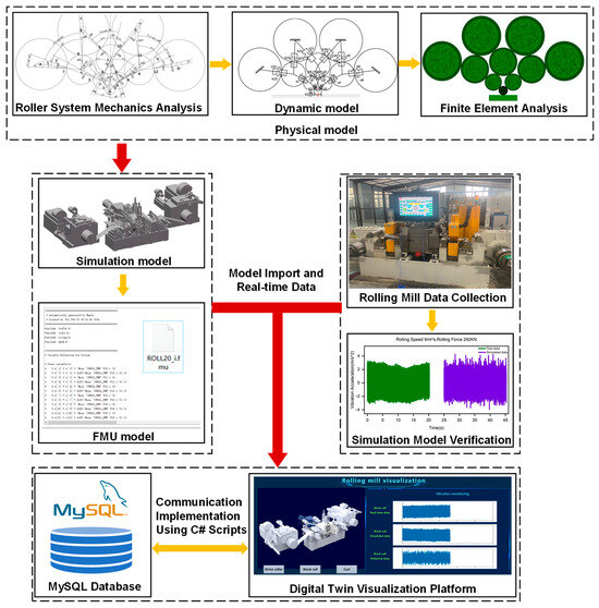
Figure 1.
The technical roadmap of this study.
The remainder of this paper is structured as follows: Section 2 elaborates on the construction of the digital twin model, encompassing roll system analysis, dynamic modeling, and finite element analysis. Section 3 describes the validation of the simulation model against on-site operational data, as well as the development of the digital twin platform. Section 4 presents the conclusions and future research directions.
2. The Construction of the Digital Twin Model and Test Platform of the Rolling Mill
In this section, the finite element analysis of the mechanical model of the twenty-high rolling mill and the development of its simulation model are presented. By analyzing the distribution and contact conditions of the rolling mill roll system, the accuracy of the roll dynamics analysis is ensured, thereby obtaining the correct inter-roll stiffness value. Then, this inter-roll stiffness value is incorporated into the finite element model to obtain the correct finite element model. By analyzing the distribution and contact conditions of the rolling mill roll system, the accuracy of the roll dynamics analysis is ensured, thereby obtaining the correct inter-roll stiffness value. Then, this inter-roll stiffness value is incorporated into the finite element model to obtain the correct finite element model. Finally, vibration data of the physical rolling mill are collected. This will enable the verification of the accuracy of the digital twin model of the rolling mill in the following content.
2.1. Analysis of the Rolling Mill Roll System
The roll system of the twenty-high rolling mill lies at the core of its design. It encompasses ten rolls on both the upper and lower parts, which can be categorized into four types as follows: work rolls, first intermediate rolls, second intermediate rolls, and backup rolls. This complex roller system layout is designed to achieve high-precision control of the rolled piece, especially in the production of extremely thin strip steel. It can be observed from Figure 2a that the roll system structure of this twenty-high rolling mill is characterized by a tower-shaped distribution arranged successively from bottom to top. Among them, rollers A–H are support rollers, rollers I–N are the second intermediate rollers, rollers O–R are the first intermediate rollers, and rollers S–T are work rollers, with their positions arranged as shown in Figure 2b. In this configuration, two sets of backup rolls A–H are, respectively, pressed firmly against six second intermediate rolls I–N. Meanwhile, the two work rolls S–T, located at the upper and lower positions, respectively, are in close proximity to these two sets of first intermediate rolls O–R. Importantly, the system design ensures that the work roll, the first intermediate roll, the second intermediate roll, and the support roll do not come into contact with each other, thus preventing any potential collision or interference.
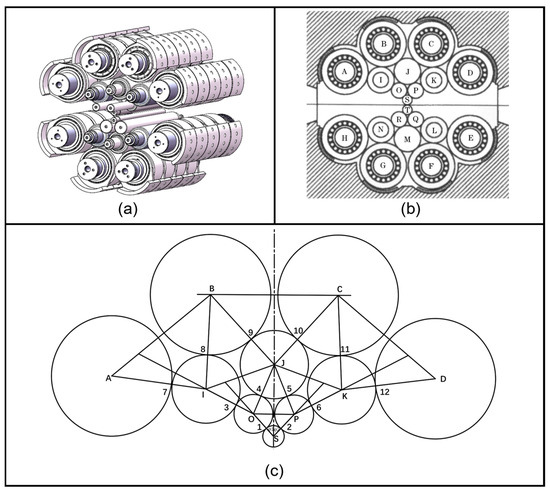
Figure 2.
(a) Schematic illustration of the roll system layout of a twenty-high rolling mill; (b) Schematic illustration of the roll arrangement of a twenty-high rolling mill; (c) Schematic illustration of the roll contact points.
In the structural diagram of the rolling mill, the roll contact points in Figure 2c are sequentially numbered from 1 to 12. At different parts of the rolling mill, the acting points of the rolling frictional force are, respectively, denoted by different identifiers.
2.2. Dynamics Analysis of Rolls in Rolling Mills
The inter-roll stiffness involves fundamental concepts in materials mechanics, including stress, strain, elastic modulus, and plastic deformation. During the rolling process, the interaction between the rolls and the rolled piece can be described by these mechanical parameters. The inter-roll stiffness not only reflects the capacity of the rolling mill to deform materials but also has an impact on the stability of the rolling process and the quality of the final product. When investigating the rolling process of a rolling mill, the crucial parameters encompass the rolling friction arm among various rolls and the diameter of the rolls. The rolling friction arm is of utmost importance for analyzing the rolling force and the energy conversion occurring in the rolling process.
Prior to commencing the rolling process, by applying equivalent tensions at the inlet and outlet ends of the rolling mill, the strip within the mill is subjected to a downward pressure. This leads to the work rolls of the rolling mill bearing an upward vertical force exerted by the workpiece. This rolling force propagates through the centers of the first intermediate roll, the second intermediate roll, and the backup roll. Ultimately, it is transmitted to the housing of the rolling mill in a radial pattern. The force analysis of the roll system of the rolls is shown in Figure 3a. Specifically, the friction lever between the work roll and the first intermediate roll is denoted by m1, which reflects the frictional characteristics between them. Similarly, for the first intermediate roll and the second intermediate roll, there exist the friction arms of the drive roll and the idler roll, denoted as m2 and m3, respectively. The friction arm between the second intermediate drive roll and the backup roll is designated as m4, while the friction arm between the second intermediate idler roll and the backup roll is specified as m5. Moreover, the radius of the friction circle of the backing bearing of the backup roll is represented by . This parameter is crucial for the analysis of the roll support system. The determination of the roll diameter is also of great significance in defining the rolling force and the distribution of rolling pressure. The diameter of the work roll is denoted by D1, while the diameters of the first intermediate rolls and the second intermediate rolls are, respectively, represented by D2, D3 and D4, D5, D6. For the sake of simplifying the calculations, it is assumed that D2 and D3 are equal, D4, D5, and D6 are equal, and D7, D8, D9, and D10 are equal. The setting of these parameters is based on the principle of symmetric arrangement of the upper and lower rolls. Through in-depth analysis of these crucial parameters, the mechanical behavior during the rolling process can be better comprehended.
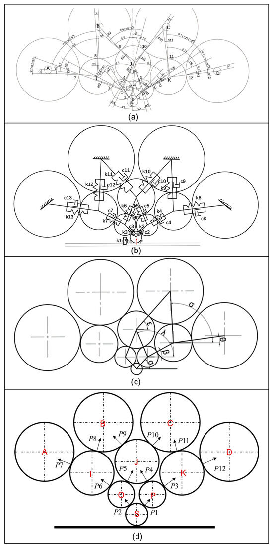
Figure 3.
(a) Force analysis diagram of the roll system of the rolls; (b) Dynamic model of the twenty-high rolling mill; (c) Relative positions and angles of the rolls; (d) Schematic of interaction forces between rolls.
The interaction forces between the rolls (P1…P12) are illustrated in Figure 3d. Specifically, the force exerted on the backing roll A is transferred to the second intermediate roll I. The interaction force between the two rolls is denoted as P7, the angle a7 between the force P7, and the line connecting roller I and roller A is determined by the following formula:
Similarly,
The direction of the force acting on the work roll is determined by the equilibrium state of the torques exerted on the work roll by the rolled piece and the first intermediate roll. It can be deduced that:
Following the direction of the forces acting on the first intermediate roll, based on the torque equilibrium conditions of the first intermediate roll, it can be deduced that:
Then:
Similarly:
Based on the analytical outcomes of the above-mentioned component forces, substituting relevant mechanical parameters into the expressions for calculations enables the acquisition of the computational results of each component force. Utilizing the basic theory and calculation methods of the pressure distribution experienced by the rolling mill during the rolling process as the input for constructing the finite element model, it is ensured that the model accurately represents the actual operating conditions. The dynamic model of the twenty-high rolling mill is established, as depicted in Figure 3b.
The elements K1C1… K13C13 in Figure 3b represent the spring-damping connection systems between rollers and the workpiece. Element F, as depicted in Figure 3b, denotes the resultant vertical force acting on the work roll. The dynamic model pertains to the motion of the rolls in the symmetric half of the rolling-mill roll system. The relative positions and angles of the rolls are presented in Figure 3c. We will introduce vibration displacement coordinates for each roller. This paper only studies the vertical component of each roller. The corresponding equation is as follows:
In the equation, , , , respectively, represent the longitudinal vibration displacement, vibration velocity, and vibration acceleration of the roller; represents the equivalent mass of each roller; represents the vertical resultant force of the work roller. Within the dynamic model, the contact stiffness between two rolls can be computed in accordance with Reference [29]. The formula is given as follows:
Among them, is the specific contact force per unit length, and refers to the elastic variation in the roll under . and denote the diameters of the two rolls, represents the elastic Young’s modulus, and stand for Poisson’s ratio.
The inter-roll stiffness values of each roll can be obtained by means of the above calculations derived from the dynamic model. These calculated values will then be incorporated into the parameter settings of the simulation model presented hereinafter.
2.3. Development of the Finite Element Model
The finite element method has been extensively employed in the analysis of metal deformation. Notably, it demonstrates remarkable effectiveness in addressing the inter-roll contact issues [30,31,32,33]. In this paper, the Sendzimir 280 mm twenty-high rolling mill is taken as the research object. Given the relatively complex structure of the roll system in the twenty-high rolling mill, it is necessary to simplify its model. Specifically, the work rolls, the first intermediate rolls, the second intermediate rolls, and the backup rolls are modeled comprehensively, respectively. All rolls in the system are simplified as cylindrical rollers with a uniform length of 280 mm. Based on the symmetrical arrangement of the upper and lower rolls, specific diameters are set to be equal as follows: D2 = D3, D4 = D5 = D6, D7 = D8 = D9 = D10, as depicted in Figure 4a. The upper portion of the roll system of the twenty-high rolling mill was modeled using SolidWorks (version 2024, Dassault Systèmes, Villacoublay, France) and saved as an assembly file in the x_t format. Subsequently, the x_t-formatted assembly file was imported into Abaqus (version 2022, Dassault Systèmes, Villacoublay, France).
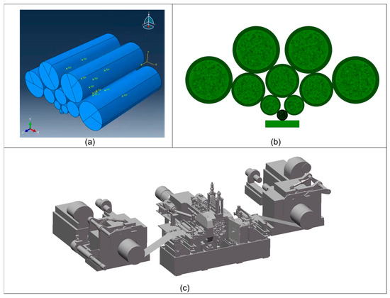
Figure 4.
(a) Three-dimensional model diagram of the simplified roll system assembly; (b) Mesh generation diagram of the simplified roll system assembly; (c) Modeling of the 20-high rolling mill.
According to the process modules of ABAQUS software, the modeling process is described as follows:
In ABAQUS/CAE, every roll exhibits variability. Within the material manager, the roller material is created. First, create the roller material; then, create the solid uniform cross-section and assign this material to it; finally, associate these cross-section properties with the corresponding components. It is assumed that the material exhibits linear elastic and isotropic characteristics. The material properties of each roller in the twenty-high roll system are presented in Table 1.

Table 1.
Relevant parameters of the roll materials for the roll system of a twenty-high rolling mill.
First, an analysis step is created. The type of this step is designated as “Static, General”, and the geometric nonlinear effects must be taken into account. Subsequently, configure the output of field variables and historical variables to ensure accurate monitoring and recording of key data during the analysis process.
Apply contact and constraints to the rolls in the model. The adopted contact type is surface-to-surface contact (explicit). In this formulation, the stiffer surface or the surface with coarser mesh was typically defined as the master surface. The normal behavior was defined with a ‘Hard’ contact pressure-overclosure relationship, which strictly enforces no penetration after contact is established. The tangential behavior was defined using the ‘Penalty’ friction formulation with a friction coefficient of 0.2, which is a standard value for lubricated steel-on-steel contact in rolling mills. This formulation is suitable for the large, rigid-body relative motion between the rolls. Finally, twelve contact pairs were set according to the actual contact mode of the rolls.
At the axial line of each roll, boundary conditions were applied to mimic bearing supports. Specifically, all translational degrees of freedom (DOFs) were constrained, while all rotational DOFs were retained. For the driven work roll, its rotational DOF about the central axis is released in subsequent dynamic analyses; however, in the present static structural analysis, this rotational DOF was fixed to represent the steady-state operation condition. Finally, a concentrated load of 97 t is applied to the work roll to simulate the force distribution in the actual working process. The 97-ton load value is not a theoretically estimated value but is directly derived from the practical process setting of the specific Sendzimir 280 mm twenty-high rolling mill targeted in this study during the production of ultra-thin steel strips. It represents a characteristic total rolling force level acting on the roll system of the mill during the stable rolling stage. The assumptions mentioned earlier regarding diameter, symmetrical arrangement, linear elasticity, and surface properties constitute common zeroth-order approximations in rolling mill modeling. While such approximations introduce certain errors (e.g., neglect of material nonlinearity and minor geometric asymmetry), they substantially reduce model complexity and computational cost. As demonstrated in the verification results (Section 3.1), these assumptions are sufficient to capture the dominant vibration behaviors required for developing an effective digital twin for monitoring purposes.
In this study, the standard first-order fully integrated hexahedral element (denoted as C3D8 in Abaqus) is adopted as the fundamental element for the computational model. In contrast to the radial meshing scheme, a structured hexahedral mesh is employed in this work, as it exhibits superior robustness in addressing the three-dimensional multi-contact characteristics of the roll stack assembly—an assembly that lacks axial symmetry along its entire length.
During the meshing process, the global mesh size is first established as the fundamental reference benchmark for mesh generation. Subsequently, local mesh refinement is implemented for regions requiring enhanced analysis accuracy—this refinement is specifically targeted at the circumferential contact surfaces of the rolls, where high stress gradients occur during loading. Accurately resolving the contact pressures and subsurface stresses in these regions is a core requirement for ensuring the model’s fidelity, which also provides a scientific rationale for the increased local mesh density. For example, local mesh refinement is applied to the contact regions of the rolls; distinct meshing schemes are employed for different types of rolls, with detailed parameters provided in Table 2.
Table 2.
Grid dimensions.
Upon completion of the meshing process and generation of the mesh, a thorough mesh quality assessment is indispensable. The aspects to be examined encompass the shape, size, and degree of distortion of the elements, among others. The resulting mesh is illustrated in Figure 4b.
Ultimately, submit the analysis task to the ABAQUS solver for computation.
Through the result analysis of finite element models with different rolling forces, various longitudinal deformation values are obtained. Subsequently, the longitudinal stiffness is computed by applying the stiffness formula, which is presented as follows:
Among them, represents the change in the rolling force and represents the elastic change in the roll under the action of the .
After calculating the stiffness value of the roll, substitute it into the parameter settings of the simulation model described later.
This paper uses SolidWorks (version 2024, Dassault Systèmes, Villacoublay, France) 3D modeling software and MAPLE SIM (version 2022, Maplesoft, Waterloo, ON, Canada) software to establish the CAD model, kinematic model and mechanical model of the 280 mm twenty-high rolling mill as a whole, and finally form a simulation model. Firstly, according to the drawings of the twenty-high rolling mill, the 280 mm diameter twenty-high rolling mill is modeled, and the material properties are defined in the SolidWorks software. The modeling result of SolidWorks is shown in Figure 4c.
Secondly, in MAPLE SIM, import the saved SLDASM assembly file and in the CAD component of MAPLE SIM, disassemble the 280 mm twenty-roll mill into the frame (Stand), base (BASE), upper work roll (GUN-S), lower work roll (GUN-T), upper first intermediate roll (GUN-O, GUN-P), lower first intermediate roll (GUN-R, GUN-Q), upper drive roll (GUN-I, GUN-K), lower drive roll (GUN-N, GUN-L), upper idler roll (GUN-J), lower idler roll (GUN-M), upper back-up roll (GUN-A, GUN-B, GUN-C, GUN-D), lower back-up roll (GUN-E, GUN-F, GUN-G, GUN-H), bearing housing of the upper first intermediate roll on the operating side (CZ-O, CZ-P), bearing housing of the upper first intermediate roll on the drive side (CD-O, CD-P), bearing housing of the upper drive roll on the operating side (CZ-I, CZ-K), bearing housing of the upper drive roll on the drive side (CD-I, CD-K), bearing housing of the lower drive roll on the operating side (CZ-N, CZ-L), bearing housing of the lower drive roll on the drive side (CD-N, CD-L), bearing housing of the upper back-up roll on the operating side (CZ-A, CZ-B, CZ-C, CZ-D), and bearing housing of the lower back-up roll on the operating side (CZ-E, CZ-F, CZ-G, CZ-H).
After grouping the defined frame and roll system in the CAD Toolbox of MAPLE SIM, the physical model of the roll system of the rolling mill frame is constructed based on the dynamic model built in the previous section. Then, the simulation model of the roll system of the rolling mill frame is established by constraining the kinematic pairs of the physical model and coupling them into the behavior model. The stiffness value obtained through the stiffness calculation method is then substituted into the damper of the model to improve it. After confirming that the model structure is correct, it is encapsulated into a twenty-roll rolling mill system, and the input and output modules are added. Finally, the FMU model is generated through the FMI interface embedded in MAPLE SIM to prepare for the visualization in the following text.
2.4. Field Data Acquisition
Rolling mill vibration testing serves as a critical method for assessing the operational condition of rolling mills. To conduct this test, a comprehensive measurement subsystem was employed. Vibration acceleration sensors (Model 1A313E, Donghua Testing Technology Co., Ltd., Taizhou, China) were mounted on the 280 mm Sendzimir twenty-high rolling mill. The charge signals generated by the sensors were transmitted via low-noise cables to a signal amplifier (Model SR570, Stanford Research Systems, Sunnyvale, CA, USA) for conditioning and amplification. Subsequently, the signals were acquired by a dynamic signal analysis system (Model DH5922D, Donghua Testing Technology Co., Ltd., China) and transmitted to a personal computer for recording and analysis. The sampling frequency was set to 1000 Hz. This setup was used to measure variations in vertical displacement, vibration frequency, and their corresponding variation patterns.
Owing to the special design of the structure, the primary sensors are configured on the rolling mill stand and the speed distribution gearbox for testing purposes. Through this layout, the vibrations generated by the rolling mill during its operation can be monitored and documented more efficiently. As the testing procedure unfolds, the collected vibration data of the rolling mill along with process data will be employed for subsequent analysis and assessment. The vibration data obtained from each measurement point will be meticulously analyzed to lay a foundation for the validation of the simulation model. The layout of the measurement points has been presented in Figure 5. Specifically, the measurement points are, respectively, located at the operating section of the rolling mill stand, the drive side of the stand, and the speed distribution gearbox. This layout enables comprehensive monitoring of the rolling mill’s vibration conditions. Moreover, it allows for targeted data analysis, thereby providing robust support for process optimization and vibration control [34].
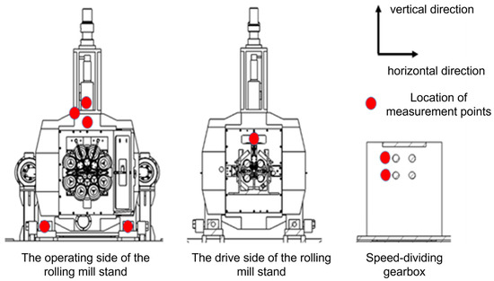
Figure 5.
The layout of measuring points of the rolling mill.
This test is conducted on a twenty-high rolling mill, with the rolling speed stabilized at 9 m/min. Through precise control and meticulous monitoring of the rolling process, it is possible to extract the vibration test data of the rolling mill stand at two distinct rolling force levels, specifically 366 KN and 292 KN. The sampling frequency was set at 1000 Hz. To ensure the accuracy and reproducibility of the frequency domain analysis results, the raw time-domain acceleration signals collected on-site were subjected to standardized post-processing. The specific steps are as follows: first, the built-in anti-aliasing filter integrated into the data acquisition system (DAS) hardware was activated during signal acquisition. To further suppress high-frequency noise and focus the analysis on the dominant vibration frequency band of the rolling mill structure, an additional digital low-pass filter with a cutoff frequency of 500 Hz was implemented in post-processing. This configuration aligns with the 1000 Hz sampling frequency, effectively preventing frequency aliasing above the Nyquist frequency (500 Hz). Second, for spectral estimation, the continuous time-domain signal was segmented into discrete data chunks. To mitigate spectral leakage during Fast Fourier Transform (FFT) processing, a Hanning window was applied to each data segment. Finally, the windowed time-domain signals were converted to the frequency domain via the FFT method. By optimizing the data length and number of averages, the resulting spectrum achieved a frequency resolution of 0.5 Hz—sufficient to clearly resolve the dominant vibration frequency components of the rolling mill. These data will be used for subsequent analysis and research to evaluate the vibration characteristics of the rolling mill under different working conditions. After calculating the stiffness value of the rolls, it will be substituted into the parameter settings of the simulation model in the following text.
3. Verification of Rolling Mill Simulation Model Operation Data, Construction, and System Verification of Digital Twin Platform
3.1. Comparative Analysis Between the Simulation of the Rolling Mill and On-Site Data
In this study, the vibration data on the drive side of the rolling mill stand were mainly compared and measured. Based on the twenty-roll mill system established in Section 2.3, data with a rolling speed of 9 m/min, rolling forces of 292 KN and 366 KN, respectively, and a sampling frequency of 1000 Hz were fed into the twenty-roll mill system. Then, the system was operated in MAPLE SIM. The vibration data corresponding to the on-site measurement points were acquired via probes. Compare the on-site test data of the rolling mill with the simulation test data of the ultra-thin strip rolling mill and conduct an in-depth analysis of the responses of the rolling mill under different rolling force conditions. Figure 6 shows the time-domain and frequency-domain results of the field test and the simulation model of the ultra-thin strip rolling mill under different rolling forces. These results provide the vibration characteristics of the rolling mill during actual operation and those of the simulation results. Key information such as vibration amplitudes and frequency distributions is included. On the other hand, these simulation results are based on precise simulation models and are intended to simulate the vibration behavior of the rolling mill under ideal conditions.
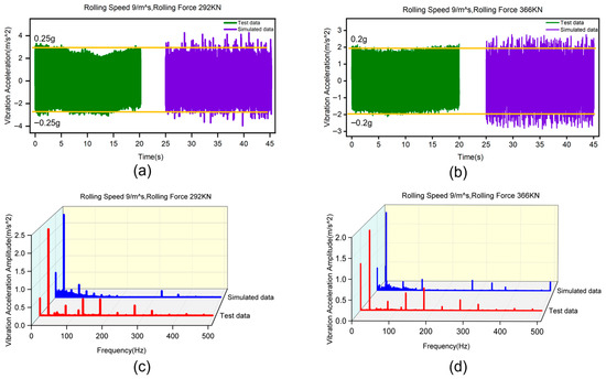
Figure 6.
Comparison of field test data and simulation model results of the ultra-thin strip rolling mill under different rolling forces: (a) time domain of vibration acceleration under 292 KN; (b) time domain of vibration acceleration under 366 KN; (c) frequency domain of vibration acceleration under 292 KN; (d) frequency domain of vibration acceleration under 366 KN.
It can be observed from Figure 6a,c that in the field test results, when the rolling force is 292 KN, the amplitude of the rolling mill stand at 28 Hz is 0.25 m/s2, and its fundamental frequency is 28 Hz. In the test results of the simulation model of the ultra-thin strip rolling mill, when the rolling force is 292 KN, the amplitude of the rolling mill stands at 30 Hz is 0.26 m/s2, and the fundamental frequency is 30 Hz. It can be observed from Figure 6b,d that in the field test results, when the rolling force is 366 KN, the amplitude of the rolling mill stands at 27 Hz is 0.2 m/s2, and its fundamental frequency is 26 Hz. In the test results of the simulation model of the ultra-thin strip rolling mill, when the rolling force is 366 KN, the amplitude of the rolling mill stands at 26 Hz is 0.21 m/s2, and the fundamental frequency is 26 Hz. Based on the monitoring results, it was found that the vibration patterns monitored by the simulation model were essentially consistent with those monitored in the field. The absolute frequency error was within 10 Hz, and the amplitude error was approximately 5%.
3.2. Establishment of the Digital Twin Platform for Rolling Mills
In this paper, the Unity 3D engine is chosen as the development tool for constructing the virtual scene. This is attributed to the fact that Unity provides robust, high-performance real-time 3D rendering capabilities, which are critical for generating interactive and immersive visualizations of complex rolling mill structures. Second, unlike certain domain-specific tools, Unity supports deep customization via C# scripting—this is essential for integrating Functional Mock-up Unit (FMU) models, establishing custom Socket-based communication with the MySQL database, and designing a tailored user interface aligned with our specific monitoring requirements. Furthermore, Unity enables cross-platform deployment (e.g., Windows, WebGL), laying the foundation for future expansion of the monitoring system to diverse terminals. Finally, the availability of Unity plugins and its extensive developer community have accelerated the development process. While specialized tools such as MLVI exist, Unity’s versatility in handling 3D visualization and complex logic integration renders it a more suitable comprehensive solution for this prototype platform.
This digital twin platform employs a two-tier communication architecture to efficiently handle both historical/configuration data and high-frequency real-time signals. For the storage and retrieval of structured data—including process parameters and historical trends—the Unity client communicates directly with the MySQL database via the standard MySQL.NET connector (a ADO.NET driver). To achieve the low-latency virtual-physical mapping required for dynamic monitoring of vibration waveforms, a dedicated TCP Socket server—implemented using the System.Net.Sockets library in C#—streams real-time data directly from the acquisition hardware to the Unity client. This hybrid communication approach ensures dual fulfillment of data persistence and real-time performance.
The real-time data of the physical rolling mill is transferred to the MySQL database via the Socket interface. The digital twin platform reads the data within the database to accomplish the dynamic mapping of the rolling mill and presents it in the visualization interface, as depicted in Figure 7. Export the model established in SolidWorks as an FBX model. Then, import the above-mentioned FBX model into the Unity software.
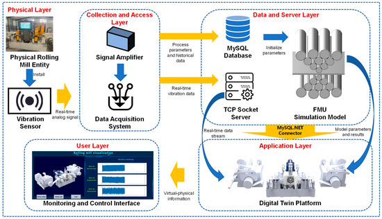
Figure 7.
The digital twin platform of rolling mill and data communication.
3.3. Application Verification of Digital Twin Platform
The dynamic changes in model attributes are achieved by collecting real-time data from the physical layer. When a new strip of material enters the rolling mill, a real-time data-driven model is called upon to operate. The virtual platform is capable of pushing diverse information regarding the rolling mill in accordance with the production status. The system monitoring status can be accessed via the PC terminal, enabling administrators to keep abreast of the real-time operating conditions of the rolling mill with ease. Figure 8 presents the real-time operation monitoring interface of the monitoring system. Figure 9 presents the data analysis display interface of the digital twin platform, which is the core of its monitoring function. This interface integrates and visualizes multiple real-time operation data streams from the physical rolling mill through the MySQL database. It shows key performance indicators such as roller running speed, vibration amplitude and frequency, and task progress. Charts and graphs are updated dynamically, enabling operators to track the status of the rolling mill intuitively. Through the initial implementation and application of this system, the dynamic collection of physical rolling mill information, the dynamic mapping of virtual rolling mill equipment operation status, and the effective monitoring of the production process have been basically achieved at present. This has effectively solved the problem of long fault response time. The degree of similarity between the virtual rolling mill and the physical rolling mill exceeds 95%, and the time delay of the virtual-physical mapping is less than 2 s.
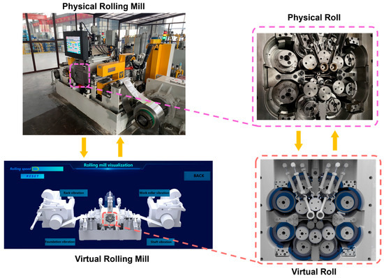
Figure 8.
The visual monitoring interface of the rolling mill.
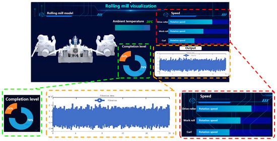
Figure 9.
The data analysis displays interface of the rolling mill.
For the Sendzimir twenty-high rolling mill investigated in this paper, its highly integrated and enclosed roll system configuration renders direct monitoring of internal vibration states challenging via conventional sensing techniques. Digital twin technology offers an effective approach to address this monitoring bottleneck by constructing a virtual model that achieves high synchronization with the physical entity. This platform not only enables multi-scale real-time mapping and full-life-cycle analysis of the rolling mill’s operational status but also provides data- and model-driven support for vibration characteristic prediction, process parameter optimization, and predictive maintenance. Consequently, it serves as a critical technical foundation for realizing intelligent operation and maintenance as well as precise control of such high-end rolling equipment.
4. Conclusions and Future Work
This paper takes the Sendzimir 280 mm twenty-high rolling mill as the research subject to conduct investigations into digital twin modeling and visualization. A finite element model and a dynamic model of the mill are developed through finite element analysis and vibration analysis, on the basis of which a digital twin system is constructed. By integrating the three-dimensional model and the FMU simulation model via Unity, the visualization of the rolling mill’s operational process is realized. This platform enables the simulation of rolling scenarios, identification of potential issues, and supports real-time information sharing, thereby offering a novel approach to enhancing the design, analysis, and operation and maintenance capabilities of rolling mills.
- (1)
- By conducting finite element analysis and dynamic modeling on the structure of the rolling mill system, a dynamic response model that can reflect the multi-field coupling effects such as rolling force and vibration on the rolling mill has been successfully established. This model integrates the structural mechanical properties of the roll system; on this basis, model order reduction (MOR) techniques are employed to construct a lightweight digital twin that exhibits consistent dynamic behavior with the physical rolling mill. This enables high-precision dynamic mapping of the physical entity in the virtual space, thereby laying a model-driven foundation for virtual-real synchronization and interaction.
- (2)
- Using real-time data such as on-site collected process parameters and vibration signals, collected from the production site, dynamic validation of the digital twin model was performed. The goodness-of-fit between the key model outputs and the actual measured data exceeded 95%. On this basis, the twin model is endowed with the capability of online prediction for abnormal vibration trends of the rolling mill during the rolling process, thus verifying the effectiveness of the digital twin model in predicting structural responses.
- (3)
- Leveraging the Unity engine, a digital twin platform supporting bidirectional data flow was constructed through the integration of a high-precision 3D model of the rolling mill, an FMU real-time simulation model, and a MySQL real-time database. This platform is equipped with functionalities including multi-scale real-time mapping of the rolling mill’s operational status and full-life-cycle analysis, thereby providing data- and model-driven support for equipment vibration characteristic prediction, process parameter optimization, and predictive maintenance. It thus opens up a novel technical pathway for enhancing the comprehensive management and control capabilities and intelligent level of ultra-thin strip rolling equipment.
Future Work
Building upon the findings of this study, several promising directions for subsequent research are proposed. Integrate additional real-time data streams and leverage advanced artificial intelligence (AI) algorithms to improve the predictive accuracy of the model. This will enable adaptive learning for rolling mill anomaly detection and root cause analysis. Extend the monitoring scope beyond vibration to encompass additional critical operational parameters, including roll temperature distribution, wear status, and strip shape quality, thereby enabling the construction of a more comprehensive digital twin that captures the full range of rolling mill behavior. Investigate the integration of the rolling mill digital twin with the plant-wide management system to enable automated operation and intelligent management of the rolling production process. Incorporate user feedback to enhance visualization fidelity and refine the user interface and integrate augmented reality (AR) technology to overlay virtual information onto physical rolling mills, thereby improving user experience. Deliver a more intuitive and efficient operational environment to support maintenance operations and personnel training.
Author Contributions
Conceptualization, Y.Z. and L.M.; methodology, Y.Z. and L.H.; software, S.W.; validation, Y.H.; formal analysis, L.H. and C.Z.; investigation, C.J.; resources, Y.Z.; data curation, S.H.; writing—original draft preparation, L.H.; writing—review and editing, C.J.; visualization, L.H.; supervision, L.M.; project administration, Y.Z.; funding acquisition, Y.Z. All authors have read and agreed to the published version of the manuscript.
Funding
This research was funded by the National Natural Science Foundation of China, grant number 52375366; the Central Leading Local Science and Technology Development Fund Project, grant number YDZJSX2025D056 and the Scientific Research Innovation Ability Support Program for Young Teachers of Shanxi Higher Education Institutions, grant number 2025Q026.
Data Availability Statement
The original contributions presented in the study are included in the article; further inquiries can be directed to the corresponding author.
Conflicts of Interest
Author Sijing Wang was employed by the Tianjin Jin An Heavy Equipment Co., Ltd. Author Shangju Hu was employed by the Shanxi Taigang Stainless Steel Precision Strip Co., Ltd. The remaining authors declare that the research was conducted in the absence of any commercial or financial relationships that could be construed as a potential conflict of interest.
References
- Xu, L.D.; Eric, L.X.; Ling, L. Industry 4.0: State of the art and future trends. Int. J. Prod. Res. 2018, 56, 2941–2962. [Google Scholar] [CrossRef]
- Zhang, W. Assembly Process Design and Key Implementation Technology Analysis of Digital Twin Drive. Equip. Technol. 2024, 17–20. [Google Scholar] [CrossRef]
- Sitahong, A.; Chen, Y.; Yuan, Y.; Wubuli, A.; Ma, J.; Mo, P. Research Review on Workshop Scheduling for Intelligent Manufacturing: Digital Twin Modeling, Optimization Algorithm, and System Architecture. Machines 2025, 13, 1021. [Google Scholar] [CrossRef]
- Wang, J.; Wen, C.; Hua, G. A survey of digital twins for concept, technology and application. Chin. J. Constr. Mach. 2023, 21, 112–116. [Google Scholar] [CrossRef]
- Yu, J.; Chen, C.; Zhang, C.; Li, P.; Ji, W. Real-Time Monitoring and Dynamic Interaction Methods Based on Digital Twin Workshop Theory. Processes 2025, 13, 685. [Google Scholar] [CrossRef]
- Yang, L.; Lai, X.; He, X.; Li, P.; Guo, Z.; Song, X. Real-Time Integration of Acceleration for Aircraft Wing Digital Twin. J. Mech. Eng. 2024, 60, 342–355. [Google Scholar]
- Qi, Q.; Tao, F.; Hu, T.; Anwer, N.; Liu, A.; Wei, Y.; Wang, L.; Nee, A.Y.C. Enabling technologies and tools for digital twin. J. Manuf. Syst. 2021, 58, 3–21. [Google Scholar] [CrossRef]
- Yang, L.; Gong, Z.; He, X.; Wang, M.; Min, Q.; Kan, Z.; Song, X. Digital Twin Construction for Structural Damage Identification. J. Mech. Eng. 2025, 61, 1–14. [Google Scholar]
- Semeraro, C.; Lezoche, M.; Panetto, H.; Dassisti, M. Digital twin paradigm: A systematic literature review. Comput. Ind. 2021, 130, 103469. [Google Scholar] [CrossRef]
- Meng, B.; Li, M.; Liu, X.; Wang, L.; Liang, S.Y.; Wang, Z. Research Progress on the Architecture and Key Technologies of Machine Tool Intelligent Control System. J. Mech. Eng. 2021, 57, 147–166. [Google Scholar] [CrossRef]
- Fu, Y.; Zhu, G.; Zhu, M.; Xuan, F. Digital Twin for Integration of Design-Manufacturing-Maintenance: An Overview. Chin. J. Mech. Eng. 2022, 35, 80. [Google Scholar] [CrossRef]
- Zhang, Y.; Du, Y.; Mao, E.; Song, Z.; Chen, D.; Zhu, Z. Pressure Control Method of Wet Clutch in High-powered Tractor Based on Digital Twin. J. Mech. Eng. 2023, 59, 268–279. [Google Scholar] [CrossRef]
- Luo, Y.-Y.; Qin, X.-D.; Xie, Y.-P.; Li, G.-L. Intelligent Data Visualization Analysis Techniques: A Survey. J. Softw. 2024, 35, 356–404. [Google Scholar] [CrossRef]
- Zheng, Y.; Yang, S.; Cheng, H. An application framework of digital twin and its case study. J. Ambient. Intell. Humaniz. Comput. 2018, 10, 1141–1153. [Google Scholar] [CrossRef]
- Novák, P.; Vyskočil, J. Digitalized Automation Engineering of Industry 4.0 Production Systems and Their Tight Cooperation with Digital Twins. Processes 2022, 10, 404. [Google Scholar] [CrossRef]
- Pan, L.; Guo, X.; Luan, Y.; Wang, H. Design and realization of cutting simulation function of digital twin system of CNC machine tool. Procedia Comput. Sci. 2021, 183, 261–266. [Google Scholar] [CrossRef]
- Wei, Y. Virtual-Reality Consistent Digital Twin Model construction and Using Method for CNC Machine Tools. Doctoral Dissertation, Shandong University, Jinan, China, 2022. [Google Scholar]
- Liu, Y.; Wang, T.; Chu, F. Knowledge Embedded Lightweight Vision Transformer for Machine Condition Monitoring. Measurement 2023, 221, 113402. [Google Scholar] [CrossRef]
- Luo, W.; Hu, T.; Zhang, C.; Wei, Y. Digital twin for CNC machine tool: Modeling and using strategy. J. Ambient. Intell. Humaniz. Comput. 2019, 10, 1129–1140. [Google Scholar] [CrossRef]
- Wei, S.; Hui, M.; Peng, L.; Chun, W.B. Research on Visual Simulation Technology Based on Manufacturing System. Modul. Mach. Tool Autom. Manuf. Tech. 2008, 9, 92–96. [Google Scholar]
- Feng, C.; Li, L.; Chen, N.; Wu, Y.; Xuan, Z. Design and Development of Numerical Control Operating Condition Monitoring System Based on Digital Twin. Tool Eng. 2024, 25, 105–109. [Google Scholar]
- Wang, J.; Niu, X.; Huang, Z.; Xuan, R. Digital twin-driven CNC machine tool virtual commissioning technology study. Manuf. Technol. Mach. Tool 2022, 127–132. [Google Scholar] [CrossRef]
- Liu, M.; Yue, C.; Xia, W.; Zhang, J.; Liu, X. Real-time monitoring of milling tool state based on digital twin. Comput. Integr. Manuf. Syst. 2023, 29, 2118–2129. [Google Scholar] [CrossRef]
- Zhao, H.; Liu, J.; Xiong, H.; Zhuang, C.; Miao, T.; Liu, J.S.; Wang, B. 3D visualization real-time monitoring method for digital twin workshop. Comput. Integr. Manuf. Syst. 2019, 25, 1432–1443. [Google Scholar] [CrossRef]
- Yuan, K.; Zhao, Z.; Li, X.; Liu, J.; Wu, C. Finite element analysis of the stability of roll system on 20-high Sendzimir mill. Steel Roll. 2018, 35, 52–56. [Google Scholar] [CrossRef]
- Jia, Z.; Li, Y.; Zhang, H.; Li, L.; Pang, S. Research on the roll system analysis technology of ZR22B52” 20-high Sendzimir rolling mil. Steel Roll. 2020, 37, 74–77. [Google Scholar] [CrossRef]
- Hu, Y.; Zhang, Y.; Ma, X.; Du, X.; Wang, W.; Zhang, H. Virtual commissioning and process parameter optimization of rolling mill based on digital twin. Int. J. Adv. Manuf. Technol. 2023, 130, 705–716. [Google Scholar] [CrossRef]
- Xue, R.; Zhang, P.; Huang, Z.; Wang, J. Digital twin-driven fault diagnosis for CNC machine tool. Int. J. Adv. Manuf. Technol. 2022, 131, 5457–5470. [Google Scholar] [CrossRef]
- Lin, Y.J.; Suh, C.S.; Langari, R.; Noah, S.T. On the Characteristics and Mechanism of Rolling Instability and Chatter. J. Manuf. Sci. Eng. 2003, 125, 778–786. [Google Scholar] [CrossRef]
- Xiao, W.; Zhang, L.; Zhu, Z. FEM analysis of casting roller intensity under aluminum strip high-speed casting condition. J. Cent. South Univ. Technol. 2000, 31, 548–551. [Google Scholar]
- Yu, H.; Liu, X.; Zhao, X.; Wu, D.; Kusaba, Y. Explicit Dynamic FEM Analysis of Multipass Vertical-Horizontal Rolling. J. Iron Steel Res. Int. 2005, 13, 26–30. [Google Scholar] [CrossRef]
- Wang, M.; Yang, H.; Sun, Z.; Guo, L.; Ou, X. Dynamic explicit FE modeling of hot ring rolling process. Trans. Nonferrous Met. Soc. China 2006, 16, 1274–1280. [Google Scholar] [CrossRef]
- Chung, W.K.; Choi, S.K.; Thomsont, P.F. Three-dimensional simulation of the edge rolling process by the explicit finite-element method. J. Mater. Process. Technol. 1993, 38, 85–102. [Google Scholar] [CrossRef]
- Huan, Z. Virtual Commissioning and Dynamic Simulation Analysis of a Twenty-Roller Mill Based on Digital Twin. Master’s Dissertation, Taiyuan University of Science and Technology, Taiyuan, China, 2023. [Google Scholar]
Disclaimer/Publisher’s Note: The statements, opinions and data contained in all publications are solely those of the individual author(s) and contributor(s) and not of MDPI and/or the editor(s). MDPI and/or the editor(s) disclaim responsibility for any injury to people or property resulting from any ideas, methods, instructions or products referred to in the content. |
© 2025 by the authors. Licensee MDPI, Basel, Switzerland. This article is an open access article distributed under the terms and conditions of the Creative Commons Attribution (CC BY) license (https://creativecommons.org/licenses/by/4.0/).