Abstract
With the rapid development of industries such as construction and port hoisting, the operational safety of truck cranes in crowded areas has become a critical issue. Under complex working conditions, traditional monitoring methods are often plagued by issues such as compromised image quality, increased parallax computation errors, delayed fence response times, and inadequate accuracy in dynamic target recognition. To address these challenges, this study proposes a personnel intrusion detection system based on multimodal sensor fusion and dynamic prediction. The system utilizes the combined application of a binocular camera and a lidar, integrates the spatiotemporal attention mechanism and an improved LSTM network to predict the movement trajectory of the crane boom in real time, and generates a dynamic 3D fence with an advance margin. It classifies intrusion risks by matching the spatiotemporal prediction of pedestrian trajectories with the fence boundaries, and finally generates early warning information. The experimental results show that this method can significantly improve the detection accuracy of personnel intrusion under complex environments such as rain, fog, and strong light. This system provides a feasible solution for the safety monitoring of truck crane operations and significantly enhances operational safety.
1. Introduction
With the accelerated advancement of China’s urbanization process and the intensive launch of large-scale infrastructure projects, the on-site environment of various engineering construction projects has become increasingly complex, and the scenarios of human-machine interactive operations have increased significantly [1,2]. As an indispensable heavy lifting equipment in modern construction, truck cranes are widely used in construction sites, transportation hubs, and other areas with dense human activities, thanks to their advantages such as strong mobility and a wide operation coverage range [3,4,5]. However, during the crane’s operations such as large-range slewing, luffing, and hoisting, its massive metal structure and dynamic moving components create significant visual blind spots. Coupled with factors like noise interference at the construction site and unordered movement of personnel, ground workers are highly prone to straying into the crane’s hazardous operation radius (such as the boom slewing area, load swinging area, outrigger extension area, etc.) due to failing to perceive the equipment’s movement status [6,7]. Once personnel intrude into hazardous areas without timely early warning, catastrophic consequences are highly likely to occur: collisions between the crane’s slewing mechanism or lifted loads and personnel may result in severe mechanical injuries or even fatal accidents; load falling caused by emergency braking could lead to secondary injuries; the accident will also interrupt the project schedule, cause equipment damage and huge compensation, seriously threaten the lives of construction workers, and exert negative impacts on the reputation of project management and social stability [8,9].
Most traditional personnel intrusion detection systems rely on a single type of sensor (such as a camera or an infrared sensor) to monitor the movement trajectories of personnel in hazardous areas [10,11]. However, these traditional methods often have the following key problems: First, single visual sensors exhibit poor robustness in complex environments (such as rainy and foggy weather, low-light conditions, etc.). The degradation of image quality leads to increased parallax calculation errors, which in turn result in missed detections or false detections. Second, many existing methods adopt a static fence design that fails to account for the dynamic changes in crane boom movements (such as slewing, luffing, etc.). This causes the fence to be unable to update in a timely manner during actual operations, thereby creating safety blind spots. Third, traditional monitoring systems only determine personnel intrusion through target detection in current images, ignoring the movement trajectories and behavioral intentions of personnel. As a result, the alarm response is delayed, making it difficult to prevent potentially dangerous behaviors in a real-time and effective manner.
In the field of construction engineering, cranes are important pieces of equipment, and their safety has always been a key focus of research. In recent years, with the advancement of technology, significant progress has been made in crane safety monitoring both domestically and internationally. Sun et al. [12] proposed a safety management method for tower cranes based on an improved visual recognition algorithm for small objects, aiming to reduce the risk of objects falling during tower crane hoisting operations. By improving the traditional YOLOv5 algorithm, additional small object detection layers and an attention mechanism were added, and the loss function was modified—these improvements enhanced the ability to accurately detect crane hooks and personnel. The improved YOLOv5s model achieved an accuracy of 96.00% and a mean average precision (mAP) of 96.42%, significantly improving detection accuracy, especially for small object detection in complex environments. By calculating the actual height of the hook and the potential object falling area, hazardous zones were identified and workers’ risk levels were evaluated; if the risk exceeded the safety threshold, a warning prompt was issued. Through real-time monitoring, this method provides an effective safety management tool, which can help prevent accidents during tower crane hoisting operations. He et al. [13] studied the application of object segmentation technology based on YOLOv11-Seg in the intelligent recognition of construction sites. This research focused on the detection and segmentation capabilities of the YOLOv11-Seg model for 13 object categories (such as excavators, bulldozers, tower cranes, workers, etc.) in construction site environments. By cleaning, annotating, and expanding the dataset, the model was trained to achieve high detection accuracy and stability, and performed well in both static and dynamic scenarios, enabling effective target recognition in complex environments. Experimental results show that the model still maintains good performance under challenging conditions such as nighttime, non-construction scenarios, and incomplete images. This study provides reliable technical support for improving safety management and intelligent monitoring of construction sites, and lays a theoretical foundation for future research and applications in related fields. Han et al. [14] proposed a multi-category target detection system for construction sites based on low-altitude remote sensing by unmanned aerial vehicles (UAVs), aiming to address the limitations of traditional target detection algorithms in construction supervision—such as reliance on fixed cameras and the ability to detect only single-category targets. The system adopts deep learning technology and uses the Swin Transformer (ST) module as its backbone network. It improves detection accuracy through a multi-scale feature fusion attention network and can detect and accurately locate 15 different types of construction site targets. Experimental results show that this method outperforms other commonly used target detection models in terms of detection accuracy. Moreover, it has been verified in actual construction sites, demonstrating excellent detection capability and robustness. This system provides an effective solution for the automated supervision of construction sites and promotes the application and development of UAVs in the construction industry. Future research can further develop construction datasets from UAV perspectives and explore integration with tracking and warning systems. Gelayol et al. [15] proposed a top-view human monitoring system based on machine learning, aiming to enhance the safety of tower crane operations in complex industrial sites. The system captures real-time video streams from above the tower crane via cameras and employs the CraneNet model to detect on-site personnel. CraneNet adopts the improved ResBlock-D module, Path Aggregation Network (PAN), and Spatial Pyramid Pooling (SPP) technology, which are designed to improve the detection accuracy of small objects, especially when the height is relatively high. Experimental results show that the system achieves a good balance between accuracy and speed: it can effectively detect workers within a distance of 50 m, and reaches an accuracy of 92.59% and a processing speed of 19 FPS on low-power devices (such as Jetson Xavier, NVIDIA, Santa Clara, CA, USA). This method has been verified in actual industrial scenarios, demonstrating its effectiveness in complex environments and providing important technical support for worker safety during tower crane operations.
To enhance the model’s speed, accuracy, and real-time responsiveness, new breakthroughs have been made in target detection algorithms. Redmon et al. proposed the one-stage target detection algorithm YOLO [16], which adopts a single-stage approach that directly extracts features within a single network structure while performing object recognition and localization simultaneously, significantly improving detection efficiency. Building on the YOLO algorithm, Redmon made improvements and proposed YOLOv2 [17] and YOLOv3 [18], with continuous enhancements in performance. Liu W et al. proposed the SSD (Single Shot Multibox Detector) detection framework [19]. Its multi-scale feature detection structure makes it faster and more flexible than YOLOv1. Bochkovskiy et al. introduced the SPP (Spatial Pyramid Pooling) network into YOLOv4 to enhance feature extraction effectiveness [20], which further improved the detection accuracy. Up to now, algorithms in the YOLO series are still undergoing continuous iteration and updates, such as YOLOv5 [21], YOLOv6 [22], SSD, and RetinaNet. The YOLO algorithm addresses object detection problems by leveraging the characteristics of regression, and uses a deep convolutional neural network to achieve fast recognition and accurate localization of targets. Owing to its advantages of high speed and high accuracy, it has been widely applied [23].
Existing YOLOv8 relies on a single visual sensor; Swin Transformer adopts fixed-weight concatenated fusion of multimodal data; and traditional radar fusion only performs simple data-level superposition. These methods suffer from low feature extraction accuracy and high false detection rates in complex environments. All existing solutions use static fences, failing to account for safety blind spots caused by the dynamic movement of crane booms. Meanwhile, current research mainly judges intrusion based on the target’s real-time position, without integrating pedestrian movement trajectories and intentions, leading to delayed alarm responses. Therefore, this study proposes a personnel intrusion monitoring system based on multimodal sensor fusion and dynamic prediction. The system integrates multimodal sensor data from binocular cameras and LiDAR (Light Detection and Ranging), and dynamically fuses features through a spatiotemporal attention mechanism, thereby enhancing the system’s adaptability to complex environments. Additionally, an improved LSTM (Long Short-Term Memory) network is used to predict the movement trajectory of the crane boom, generating a dynamic 3D fence with advance allowance. This dynamic 3D fence can adjust its position according to the real-time movement of the crane boom, effectively avoiding the blind spot problem of static fences. Furthermore, the system combines pedestrian trajectory prediction and behavioral intention analysis, using the Kalman filter and Transformer model for trajectory prediction to identify potential intrusion risks in advance, thus achieving accurate monitoring and early warning of personnel intrusion behaviors.
2. System Design and Methodology
The monitoring of personnel intrusion into hazardous areas during tower crane operation is premised on accurate hazardous area modeling, multimodal sensor data fusion, real-time personnel trajectory tracking and prediction, dynamic 3D fence updating, and timely early warning responses. To enhance personnel safety during truck crane operations, this study proposes a personnel intrusion monitoring system based on multimodal sensor fusion and dynamic prediction. The system employs multimodal sensors that combine binocular cameras and LiDAR, achieves dynamic data fusion through a spatiotemporal attention mechanism, and integrates boom movement prediction to generate a dynamic 3D fence, thereby enabling real-time monitoring and providing early warnings for personnel intrusion into hazardous areas.
2.1. Data Acquisition and Spatiotemporal Registration
The data acquisition module of the system includes binocular cameras, LiDAR, and auxiliary sensors (e.g., inclinometers). Through these sensors, the system can collect real-time RGB images, disparity maps, and 3D point cloud data of the operation area. The RGB images and disparity maps captured by the binocular cameras are used to acquire visual information of the crane operation area; LiDAR is used to obtain 3D point cloud data of this area. A hardware-triggered synchronization method is adopted to ensure that data from different sensors can be aligned within the same timestamp, thereby reducing the impact of time errors.
To fuse data from different sensors under the same coordinate system, the system obtains the extrinsic parameters between sensors through hand-eye calibration and transforms the LiDAR point cloud into the camera coordinate system. The formula is as follows:
where is the three-dimensional coordinate (m) in the camera coordinate system, is the three-dimensional coordinate (m) in the lidar coordinate system, is the 3 × 3 orthogonal rotation matrix, and is the 3 × 1 translation vector (m).
Through this registration process, the point cloud data collected by LiDAR is converted into 3D coordinates under the camera coordinate system, enabling the spatial alignment of the two types of data. This thereby provides accurate input for subsequent data fusion and analysis.
2.2. Spatiotemporal Attention Feature Fusion
To enhance the robustness and accuracy of multimodal data in complex environments, this study adopts a spatiotemporal attention mechanism to fuse visual features and point cloud features. This mechanism dynamically adjusts the weights of data from different modalities based on the temporal and spatial characteristics of the data.
Visual feature adopts an improved CSPDarknet network, and strengthens human body region features through the Coordinate Attention Module (CAM). The calculation process of CAM is as follows:
Among them, is the input feature map; is the global average pooling operation; is the 1 × 1 convolution operation.
The output dimension is (where and are the height and width of the feature map, and is the number of channels); for point cloud feature , the point cloud is divided into 8 cm × 8 cm × 8 cm voxels using VoxelTransformer, and spatiotemporal features (including voxel density and motion vectors) are extracted, with an output dimension of (where is the number of point cloud feature channels).
By introducing weights in the temporal dimension, the spatiotemporal attention mechanism dynamically allocates cross-modal feature weights. The fusion formula is as follows:
Among them, denotes the timestamp (in milliseconds, ms), and represents the spatial attention mask, whose calculation formula is as follows:
Among them, denotes the 3 × 3 convolution operation, represents the max-pooling operation, and stands for the activation function; is the temporal attention weight, whose calculation formula is as follows:
Among them, denotes the feature difference between adjacent frames, and represents the natural constant.
The flow chart of the spatiotemporal attention fusion mechanism is shown in Figure 1.
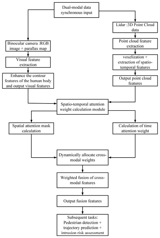
Figure 1.
Flow Chart of Spatiotemporal Attention Fusion Mechanism.
2.3. Dynamic 3D Fence Generation
During the operation of a crane, the movement trajectory of the crane boom is constantly changing, and traditional static fences cannot promptly adapt to the changes caused by the boom’s movement. To address this issue, this study proposes a dynamic 3D fence generation method based on crane boom movement prediction, ensuring that the fence adapts to the boom’s position and movement state in real time. As shown in Figure 2.
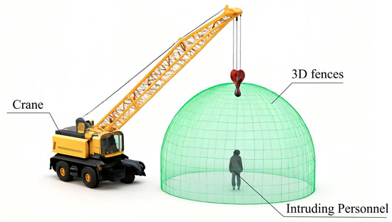
Figure 2.
Schematic Diagram of the 3D Fence.
This study adopts an improved LSTM network (with an attention mechanism integrated) to predict the position of the crane boom tip in the next 1 s. The prediction formula is as follows:
Among them, denotes the predicted coordinates (in meters) of the crane boom tip at time s; represents the LSTM hidden state; is the actual coordinates (in meters) of the crane boom tip at time ; stands for the boom elevation angle (in degrees) at time ; indicates the boom slewing angular velocity (in degrees per second) at time ; refers to the boom luffing speed (in meters per second) at time .
A three-dimensional fence with an advance margin is generated based on the predicted trajectory, and its radial radius is:
Among them, denotes the boom length (in meters) at time ; represents the actual load (); is the rated load (); stands for the predicted linear velocity of the boom tip (in meters per second); indicates the slope correction coefficient; refers to the ground slope angle (in degrees, obtained by the inclinometer).
Height Threshold:
Among them, denotes the reference height of the crane turntable (m); represents the predicted acceleration of the boom tip (m/s2).
The flow chart of dynamic 3D fence generation is shown in Figure 3.
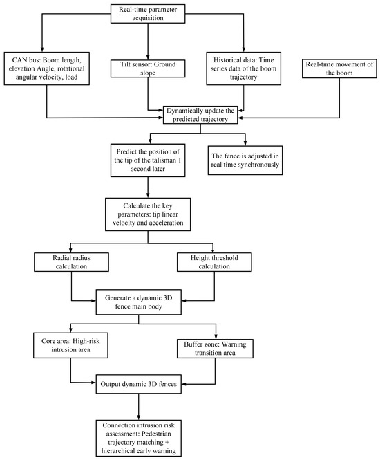
Figure 3.
Flow Chart of Dynamic 3D Fence Generation.
2.4. Pedestrian Trajectory Prediction and Intrusion Risk Assessment
To improve the accuracy of intrusion detection, this study introduces the Kalman filter and Transformer model for pedestrian trajectory prediction. By predicting the future positions of pedestrians, the system can identify potential intrusion risks in advance and determine whether pedestrians have entered dangerous areas through spatiotemporal matching.
The Kalman filter combined with the Transformer is used to predict the pedestrian’s position in the next 0.5 s, and the formula is as follows:
Among them, denotes the predicted coordinates (in meters) of the pedestrian at time ; represents the actual coordinates (in meters) of the pedestrian at time ; stands for the pedestrian’s velocity (in meters per second) at time ; indicates the pedestrian’s acceleration (in meters per second squared) at time ; and refers to the Kalman filter operator.
Intrusion risks are determined through spatiotemporal matching, and the grading formula is as follows:
Among them, Fence refers to the dynamic 3D fence at Time ; the buffer zone is the 1-m range inside the fence; the core area is the area inside the buffer zone; represents the outward normal vector of the fence boundary (a unit vector); indicates that the pedestrian is moving toward the inside of the fence, and indicates that the pedestrian is not moving toward the inside.
3. Experimental Verification
To verify the effectiveness of the proposed method, experiments were conducted in complex environments such as rain, fog, and strong light in this study. The deployment scenario of this experiment is a 25-ton truck crane, and the personnel intrusion detection was implemented in a construction site scenario. The system deployment is as follows:
3.1. Multimodal Perception Layer
This study adopts the ZED2 stereo camera (Stereolabs, San Francisco, CA, USA), which consists of two industrial cameras installed side by side. It has a side-by-side resolution of 2208 × 1242 and a refresh rate of 60 Hz, supporting real-time and high-precision distance measurement tasks. The lens is oriented toward the boom operation area (with a horizontal field of view covering 120°), as shown in Figure 4a. A 16-channel LiDAR (Hesai Technology (Hesai), Shanghai, China) (Model: RoboSense RS-LiDAR-16; Horizontal FOV: 120°; Point Cloud Density: 200 points/m2; Ranging Range: 0.5–100 m) is adopted in this study. It is installed on the left side of the front end of the turntable to ensure that the field of view overlaps with that of the camera by ≥80%, as shown in Figure 4b. Auxiliary sensors: The Inclination Sensor (Nanjing Sky MEMS Technology Co., Ltd., Nanjing, China) (Model: SCA100T, Accuracy: ±0.1°) is installed on the horizontal platform of the turntable and used to collect the ground slope; the CAN bus interface is connected to the crane’s ECU to obtain boom parameters in real time (including length , elevation angle , slewing angular velocity , load mload , etc.), as shown in Figure 4c.
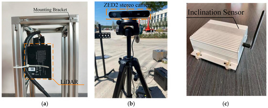
Figure 4.
Schematic Diagram of Infrastructure Equipment. (a) LiDAR. (b) ZED2 stereo camera. (c) Inclination Sensor.
3.2. Data Processing Layer
NVIDIA Jetson AGX Orin (NVIDIA, Santa Clara, CA, USA) and Xilinx K7 FPGA (Xilinx Inc. (now part of AMD), San Jose, CA, USA) are adopted, which are deployed in the control cabinet of the crane cab and are responsible for data fusion and model inference.
3.3. Hardware Platform
To verify the reliability of the personnel intrusion detection system studied in this paper in real-world scenarios, this paper builds a working condition safety monitoring platform based on the QY25K5C_1 crane (XCMG Group, Xuzhou, China). The monitoring platform adopts a cloud-edge-device integrated architecture in its implementation. For the transmission of on-site perception data, a wireless local area network (WLAN) based on Long Range Radio (LoRa) technology is used, which includes an acquisition host and acquisition terminals. The acquisition host communicates with the acquisition terminals via a LoRa network; equipped with 4G and 5G modules, the acquisition host uploads data to the cloud platform through the mobile public network (APN). The platform management host is used for platform information maintenance, as shown in Figure 5.
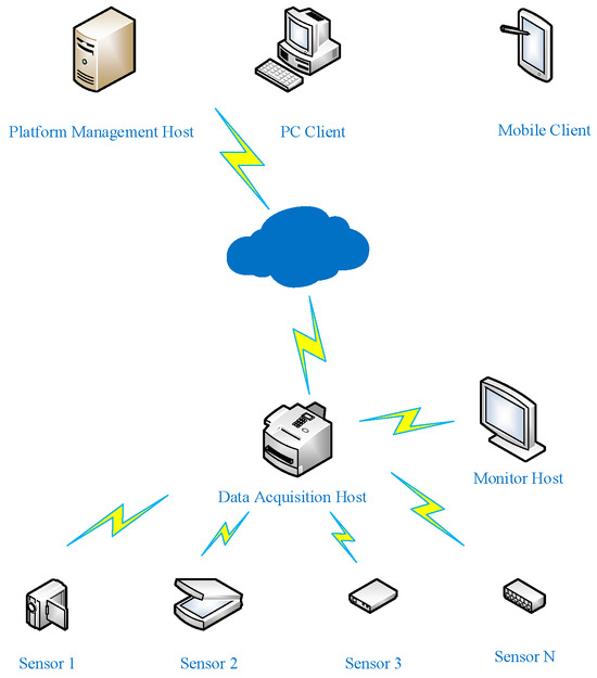
Figure 5.
Network Structure Diagram of the Monitoring Platform.
The system configuration of the truck crane working condition safety monitoring platform built in this paper is shown in Table 1.

Table 1.
System Configuration.
3.4. Software Platform
To facilitate communication between the modules of the intelligent monitoring platform, the experiment adopts the Robot Operating System (ROS)—a multifunctional distributed architecture—for implementation. ROS exhibits excellent compatibility with the Ubuntu system running on the Linux kernel, which greatly simplifies the experiment operations. The software environment for the experiment in this paper is based on the Ubuntu 18.04 system, on which the corresponding ROS Melodic version is installed; meanwhile, the ROS operating environment is configured. The specific configuration of the experimental environment is shown in Table 2.
Table 2.
Specific Configuration of the Experimental Environment.
3.5. Decision-Making and Execution Layer
The dynamic fence engine receives the operating parameters of the CAN bus, runs the LSTM prediction model, and updates the fence boundary every 50 ms. The alarm device outputs the risk level according to the risk grading formula and drives the graded response, as shown in Table 3.
Table 3.
Risk Classification and Response.
3.6. Specific Implementation
Taking “boom slewing operation (angular velocity: ) + rain-fog environment (visibility: 50 m)” as an example, the stereo camera collects RGB images (including rain-fog blurred areas) and disparity maps, while the LiDAR synchronously collects 3D point clouds (penetrating rain and fog to output clear point clouds); the timestamp alignment between the camera and LiDAR is achieved via GPIO trigger signals; a chessboard calibration board (specifications: 12 × 10 grids, grid spacing: 50 mm) is used to complete hand-eye calibration and obtain external parameters:
Rotation Matrix:
Translation Vector:
The LiDAR point cloud is converted to the camera coordinate system using the coordinate transformation formula:
8 cm × 8 cm × 8 cm voxel filtering is adopted to remove noise points caused by rain and fog; adaptive histogram equalization is performed on the stereo images to enhance the contrast of rain-fog areas;
Visual Feature is extracted using the improved CSPDarknet + CAM (Channel Attention Module) to enhance the human contour features in the image; Point Cloud Feature extracts voxel features via VoxelTransformer (human point cloud density ≈ 50 points/m2, with normal vectors perpendicular to the ground); the spatial attention mask = 0.3 (reducing the visual weight of rain-fog areas), and the temporal attention weight = 0.8 (pedestrian motion features are prominent); the feature fusion process is as follows:
Lift arm parameters: current = 10 m, = 30°, = 5°/s, = 5 (rated load = 10), ground slope = 3°;
Boom Trajectory Prediction: The improved LSTM is used to predict the future 1-s tip position , and the predicted linear velocity = 0.87 m/s and acceleration = 0.1 m/s2 are calculated;
Fence Radial Radius:
Height Threshold:
The fence is a cylindrical area with a radius of 6.03 m and a height range of 0.5–2.0 m (where the core area is defined as R ≤ 5.03 m, and the buffer zone is 5.03–6.03 m in radius).
Pedestrian Detection: Feature (the fused feature) is used to identify 1 pedestrian (with coordinates , speed , and direction facing the boom);
Trajectory Prediction: The Kalman filter is used to predict Position after 0.5 s;
Risk Determination: falls into the core area (5.1 m ≤ 5.03 m) and meets condition (moving inward); the risk level is Risk = 2. A Level-3 alarm is triggered, the boom power is cut off, and the red stroboscopic light and buzzer are activated.
Through multiple sets of tests, the probability of successful pedestrian recognition is over 95%, the alarm response time is less than 1 s, Table 4 presents the comparative results of different experimental methods. The error of our proposed method is less than 3%, which is relatively accurate, and the experimental results meet the requirements.
Table 4.
Experimental Data of Personnel Intrusion Detection.
4. Conclusions
This study proposes a personnel intrusion detection method for truck cranes based on multimodal sensor fusion and dynamic prediction. Unlike existing systems that rely on a single sensor (such as YOLO-based visual recognition or radar-based methods), our system integrates binocular cameras and Light Detection and Ranging (LiDAR). By fusing visual information and spatial data, it enhances the robustness and accuracy of the system in complex environments (e.g., haze, rainy weather, or low-light conditions). The spatiotemporal attention mechanism dynamically adjusts the fusion of multi-modal features, further improving detection performance. Most existing methods utilize static fences based on preset regions, which fail to adapt to changes in the movement of crane booms. In contrast, the proposed system can generate dynamic 3D fences in real time according to the movement trajectory of crane booms, significantly reducing safety blind spots. Different from YOLO-based or radar-based systems that only rely on current position information for intrusion detection, our system predicts pedestrians’ movement trajectories through the Kalman filter and Transformer model. This predictive capability enables the system to identify potential intrusions in advance and issue early warnings, thereby achieving more timely interventions.
In terms of boom movement, this study adopts an improved LSTM network to predict the boom’s motion trajectory. Combined with the boom’s motion state and actual working environment, a dynamic 3D fence with an advance margin is generated. This dynamic 3D fence can adapt to complex movements of the boom, such as slewing and luffing, in real time, avoiding the problem that traditional static fences cannot be adjusted in a timely manner, thereby effectively eliminating safety blind spots.
By predicting pedestrian trajectories using the Kalman filter and Transformer model, the system can not only accurately identify potential intruders but also provide early warnings for dangerous behaviors in advance. Experimental results show that the proposed method can operate stably in various complex environments and achieve a significant improvement in accuracy. Additionally, the response speed of the system has been significantly optimized, enabling it to issue warnings for intrusion behaviors within 0.5 s.
The contributions of this study lie not only in proposing an efficient and robust intrusion detection system but also in providing an intelligent solution for personnel safety during crane operations. This system can be widely applied in scenarios such as construction sites and port hoisting operations, and is particularly suitable for personnel safety monitoring in dynamic environments, thus holding broad application prospects.
However, despite the good results achieved by the system in practical applications, there are still some challenges and areas for improvement. First, the current system mainly relies on the quality of sensor data and environmental adaptability. Future research can further optimize the integration and processing of multimodal sensors to enhance the system’s robustness in more complex and changeable environments. Second, with the continuous development of intelligent technologies, more intelligent algorithms—such as deep reinforcement learning—can be integrated in the future to further improve the system’s prediction accuracy and real-time response capability. Finally, the hardware deployment and computing capacity of the system remain a bottleneck restricting its wide application. In the future, technologies such as hardware acceleration and edge computing can be used to further improve the system’s response speed and stability.
In summary, this study provides an innovative technical solution for personnel intrusion detection during crane operations and offers new ideas and practical approaches for safety management under complex working conditions. In the future, with the continuous advancement of technology, the system will play an important role in more application scenarios, providing strong support for improving operational safety and safeguarding the lives of personnel.
Author Contributions
Software, F.X.; Validation, W.B.; Formal analysis, F.W.; Investigation, M.H.; Data curation, M.H.; Writing—original draft, Z.Z.; Writing—review & editing, F.W.; Visualization, W.B.; Supervision, F.X. All authors have read and agreed to the published version of the manuscript.
Funding
This work was supported by the State Grid Shandong Electric Power Company Science and Technology Project [Grant No.: 520607240009].
Data Availability Statement
Data supporting the findings of this study are available from the corresponding authors upon reasonable request.
Conflicts of Interest
Authors Fengyu Wu and Maoqian Hu were employed by the company Linyi Power Supply Company of State Grid Shandong Electric Power Company. Author Fangcheng Xie was employed by the company Yantai Penglai District Power Supply Company of State Grid Shandong Electric Power Company. The remaining authors declare that the research was conducted in the absence of any commercial or financial relationships that could be construed as a potential conflict of interest.
References
- Marco, D.G.; Niederwieser, E.; Siegele, D. Exploring a Multimodal Conversational Agent for Construction Site Safety: A Low-Code Approach to Hazard Detection and Compliance Assessment. Buildings 2025, 15, 3352. [Google Scholar] [CrossRef]
- Nubert, J.; Khattak, S.; Hutter, M. Graph-based Multi-sensor Fusion for Consistent Localization of Autonomous Construction Robots. In Proceedings of the 2022 International Conference on Robotics and Automation (ICRA), Philadelphia, PA, USA, 23–27 May 2022; pp. 10048–10054. [Google Scholar] [CrossRef]
- Liu, Z. Exploration and Research on Safety Management Mechanism of Tower Cranes on Construction Sites. Front. Econ. Manag. 2025, 6, 190–194. [Google Scholar] [CrossRef]
- Akber, Z.M.; Chan, K.W.; Lee, H.H.; Anwar, G.A. TPE-Optimized DNN with Attention Mechanism for Prediction of Tower Crane Payload Moving Conditions. Mathematics 2024, 12, 3006. [Google Scholar] [CrossRef]
- Ali, H.A.; Zayed, T.; Wang, D.R.; Kit, M.Y.S. Tower crane safety technologies: A synthesis of academic research and industry insights. Autom. Constr. 2024, 163, 163105429. [Google Scholar] [CrossRef]
- Pazari, P.; Didehvar, N.; Alvanchi, A. Enhancing Tower Crane Safety: A Computer Vision and Deep Learning Approach. Eng. Proc. 2023, 53, 38. [Google Scholar] [CrossRef]
- Tong, R.; Guo, B.; Chen, S.; Liu, P.; Ding, Q. Analysis of Safety Management for Truck Cranes on Construction Sites. Acad. J. Archit. Geotech. Eng. 2023, 5, 29–34. [Google Scholar] [CrossRef]
- Bo, C.; Wang, T.; Yn, Y.; Wang, H.Y.; Xiao, Y.; Yang, Z.Y.; Li, W.Z. Research on the self-correction method of substation crane operation safety height based on Kalman filter. J. Phys. Conf. Ser. 2022, 2310, 012022. [Google Scholar] [CrossRef]
- Haitao, W.; Botao, Z.; Heng, L.; Chi, H.-L.; Wang, Y. On-site safety inspection of tower cranes: A blockchain-enabled conceptual framework. Saf. Sci. 2022, 153, 105815. [Google Scholar] [CrossRef]
- Price, L.C.; Jingdao, C.; Jisoo, P.; Cho, Y.K. Multisensor-driven real-time crane monitoring system for blind lift operations: Lessons learned from a case study. Autom. Constr. 2021, 124, 103552. [Google Scholar] [CrossRef]
- Yong, Z.; Zhengkang, F.; Jie, Z.; Li, W.; Gao, C. A Digital Twin-Based Operation Status Monitoring System for Port Cranes. Sensors 2022, 22, 3216. [Google Scholar] [CrossRef]
- Sun, X.; Lu, X.; Wang, Y.; He, T.; Tian, Z. Development and Application of Small Object Visual Recognition Algorithm in Assisting Safety Management of Tower Cranes. Buildings 2024, 14, 3728. [Google Scholar] [CrossRef]
- He, L.; Zhou, Y.; Liu, L.; Ma, J. Research and Application of YOLOv11-Based Object Segmentation in Intelligent Recognition at Construction Sites. Buildings 2024, 14, 3777. [Google Scholar] [CrossRef]
- Han, L.; Cho, J.; Seo, S. Construction Site Multi-Category Target Detection System Based on UAV Low-Altitude Remote Sensing. Remote Sens. 2023, 15, 1560. [Google Scholar] [CrossRef]
- Gelayol, G.; Ignacio, A.M.; Qi, W.; Alcaraz-Calero, J. Machine-learning-based top-view safety monitoring of ground workforce on complex industrial sites. Neural Comput. Appl. 2021, 34, 4207–4220. [Google Scholar] [CrossRef]
- Ahmad, T.; Ma, Y.; Yahya, M.; Ahmad, B.; Nazir, S.; Haq, A.U. Object detection through modified YOLO neural network. Sci. Program. 2020, 2020, 8403262. [Google Scholar] [CrossRef]
- Li, X.; Shi, B.B.; Nie, T.T.; Zhang, K.; Wang, W. Multi-object recognition method based on improved yolov2 model. Inf. Technol. Control. 2021, 50, 13–27. [Google Scholar] [CrossRef]
- Zhao, L.; Li, S. Object detection algorithm based on improved YOLOv3. Electronics 2020, 9, 537. [Google Scholar] [CrossRef]
- Liu, W.; Anguelov, D.; Erhan, D.; Szegedy, C.; Reed, S.; Fu, C.-Y.; Berg, A.C. Ssd: Single shot multibox detector. In Proceedings of the Computer Vision–ECCV 2016: 14th European Conference, Amsterdam, The Netherlands, 11–14 October 2016; Proceedings, Part I 14. Springer International Publishing: Cham, Switzerland, 2016; pp. 21–37. [Google Scholar]
- Bochkovskiy, A.; Wang, C.Y.; Liao, H.Y.M. Yolov4: Optimal speed and accuracy of object detection. arXiv 2020, arXiv:2004.10934. [Google Scholar] [CrossRef]
- Kim, J.H.; Kim, N.; Park, Y.W.; Won, C.S. Object detection and classification based on YOLO-V5 with improved maritime dataset. J. Mar. Sci. Eng. 2022, 10, 377. [Google Scholar] [CrossRef]
- Li, C.; Li, L.; Jiang, H.; Weng, K.; Geng, Y.; Li, L.; Ke, Z.; Li, Q.; Cheng, M.; Nie, W.; et al. YOLOv6: A single-stage object detection framework for industrial applications. arXiv 2022, arXiv:2209.02976. [Google Scholar] [CrossRef]
- Nan, L. Simulation and Prediction of the Safety Risk of Tower Crane for Super High-rise Buildings Through Back Propagation Neural Network. IOP Conf. Ser. Earth Environ. Sci. 2021, 783, 012030. [Google Scholar] [CrossRef]


Disclaimer/Publisher’s Note: The statements, opinions and data contained in all publications are solely those of the individual author(s) and contributor(s) and not of MDPI and/or the editor(s). MDPI and/or the editor(s) disclaim responsibility for any injury to people or property resulting from any ideas, methods, instructions or products referred to in the content. |
© 2025 by the authors. Licensee MDPI, Basel, Switzerland. This article is an open access article distributed under the terms and conditions of the Creative Commons Attribution (CC BY) license (https://creativecommons.org/licenses/by/4.0/).