Abstract
Land subsidence caused by groundwater withdrawal remains a significant challenge in urbanized regions, requiring robust predictive models to manage its impact effectively. In this study, a set of coupled partial differential equations is formulated using Biot’s poroelasticity theory and Darcy’s law to model the hydro-mechanical behavior of a multi-aquifer system. The numerical models capture the coupled dynamics of fluid flow and subsurface deformation induced by groundwater table depression. Hydraulic head reductions, vertical compaction, and lateral deformation patterns over a 10-year pumping period are systematically examined. The results manifest that greater hydraulic gradients near geological discontinuities, such as bedrock steps, induce localized deformation and stress redistribution. While Terzaghi’s model effectively predicts vertical compaction in simple systems, Biot’s model accounts for lateral strain and coupled feedback mechanisms, providing a more comprehensive analyses and understanding of subsidence phenomena. This study highlights the importance of coupled hydro-mechanical modeling for accurately predicting land subsidence and offers insights into managing groundwater extraction in geologically complex regions.
1. Introduction
Land subsidence refers to the slow or sudden sinking of the ground surface caused by the deformation of underground earth materials, and it is a widespread issue in urban regions [1,2,3,4]. The primary factor contributing to land subsidence is the consolidation of soil induced by excessive withdrawal of groundwater, which is a worldwide problem and has occurred in many cities, for example, Bangkok, Venice, Mexico, Shanghai and so on [5,6,7,8,9,10]. Therefore, analyzing and predicting soil consolidation due to groundwater withdrawal in a multi aquifer system is important for achieving the control of land subsidence and the sustainable use of groundwater resource. The most widely used theories of consolidation behavior are Terzaghi [11], and Biot [12].
Land subsidence is frequently modeled or assessed using the soil consolidation theory, which describes the volumetric changes in soil caused by water pressure. Early approaches to simulating soil consolidation were based on Terzaghi’s theory, which assumes that both settlement and water flow occur vertically. However, neglecting horizontal deformation limits the ability to fully analyze consolidation-related issues [3].
When horizontal deformation must be taken into account, the one-dimensional consolidation theory may no longer be applicable [13]. In recent years, Biot’s poroelasticity theory, which incorporates both horizontal and vertical components of elastic deformation, has become widely adopted for addressing land subsidence issues. Ammons and Vable examined settlement resulting from surface loading and land subsidence due to pumping in saturated layered soils [14]. Xu et al. presented prediction methods for land subsidence used in China, concluding that Biot’s consolidation theory provides a more accurate simulation of field data [15]. Furthermore, Ferronato et al. proposed a coupled Biot’s model, utilizing a three-field formulation to predict land subsidence in the Chaobai river alluvial fan in China [16,17]. Chang, and Huang applied the linear poro elasticity theory to investigate the soil consolidation of multi-aquifer system caused by groundwater level decline due to pumping, but these studies did not consider the viscous coupling caused by viscous drag [18,19]. In addition, the two-dimensional plane-strain consolidation problem with distributed drainage boundary in sand blankets overlying clays were explored for soft soil treatment [20]. The finite strain-based dual-component model, grounded in the finite strain theory within the framework of continuum mechanics was employed to reveal the correlations among stress-dependent properties of rocks [21].
However, the existing models are merely involved in one single theory with respect to the reference configuration rather than the current configuration. This treatment may induce inaccuracies, particularly under conditions with variable hydarulic levels and exposure of artifically extracting groundwater. To address the limitations concerning the coupling between fluid flow and deformation, this study analyzes the soil consolidation due to groundwater table depression in a multiaquifer system over a 10-year pumping period, enabling a comparative evaluation of Terzaghi’s compaction theory and Biot’s poroelasticity model. This paper emphasizes the critical role of coupled hydro-mechanical modeling in understanding land subsidence and offers actionable insights into the strengths and limitations of traditional and advanced approaches. These findings can better contribute to the development of robust strategies for groundwater management and subsidence mitigation in geologically complex settings.
2. Methodology
2.1. Numerical Model of an Aquifer
The numerical model for simulating land subsidence in this study is adapted from the work of [22,23] to investigate land subsidence resulting from aquifer compaction. The model simulates an aquifer system located above an impermeable bedrock within a basin. The bedrock features a fracture, creating a ledge adjacent to a mountain face. The sediment accumulation along the basin’s centerline (x = 0 m) measures 420 m and thins to 120 m above the step (x > 4000 m). The upper two strata each have a thickness of 20 m Figure 1. For the validity and reliability of the model, this study has implemented the quantitative validations employing the field data from ref. [22], with an impressive R2 value of 0.9892.
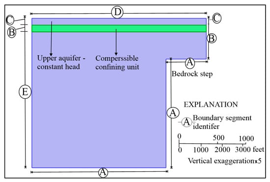
Figure 1.
Schematic representation of the model geometry, illustrating the boundary segments (A through E), highlights key geological features and boundary conditions applied in the simulation.
Groundwater extraction from the lower aquifer leads to a 6 m annual decrease in hydraulic head along the basin’s centerline. This head drop displaces fluid away from the step. The intermediate layer exhibits low permeability, preventing significant fluid exchange with the unpumped reservoir above it. The flow field is initially in a steady state, and the study focuses on a ten-year period.
The study utilized COMSOL Multiphysics 6.3 predefined mesh grid, opting for a finer element size Figure 2, to enhance simulation accuracy. The maximum element size is set at 192 m. While finer meshes can improve accuracy, they also significantly increase computational costs. Therefore, a balance must be struck between solution accuracy and computational efficiency. The coefficients and parameters used in the poroelasticity model are presented in Table 1.
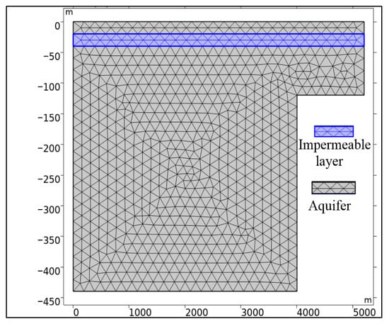
Figure 2.
Detail of the mesh grid used in the numerical model, showing the finer element size (maximum element size of 192 m) to ensure higher resolution in the simulated domain while balancing computational efficiency.

Table 1.
The coefficients and parameters used in the poroelasticity model.
Given the large area to be simulated, the maximum element size employed in this study exceeds the correlation length of some model parameters. To address this, the midpoint discretization method, as described by [7,24], is used to determine the grid points of the random field. Shen et al. demonstrated that this method is sufficient to obtain accurate statistics of model responses [25]. For a detailed discussion of finite element meshes and discretization error, refer to [26].
2.2. Biot’s Poroelasticity
In this investigation, we utilized the integrated module within COMSOL Multiphysics 6.3 [23] to conduct simulations of land subsidence processes. Based on Biot’s poroelastic theories [9,23], the Poroelasticity Multiphysics node incorporates the time-dependent strain rate from the Solid Mechanics interface into Darcy’s Law. Additionally, it integrates the fluid pressure gradient as a stress component within the Solid Mechanics interface. The following sections outline the equations provided by the Poroelastic Material feature, along with the initial and boundary conditions.
2.3. Governing Equations
2.3.1. Fluid Flow
Use the Darcy’s Law interface to estimate the flow field in the poroelastic model with the pressure head formulation:
which ρf represents the fluid density, H denotes the pressure head (in meters), K is the hydraulic conductivity (in meters per second), Evol is the volumetric strain of the porous matrix, and αB is the Biot–Willis coefficient. For this model, αB is set to 1, which is a typical value for soft soils. The term on the right-hand side represents the rate of expansion of the porous matrix over time. This expansion increases the volume fraction available for fluid, effectively creating a liquid sink, which explains the reversed sign in the source term. Leake and Hsieh defined Sα using material properties such as Young’s modulus, E, and Poisson’s ratio, (ν) derived from the solid’s equations [22]. There is ongoing debate about poroelastic storage coefficients [27], with the subscript α here indicating that traditional storage terms may need to be reinterpreted in the context of poroelastic models.
The primary distinctions between the Terzaghi compaction model and this poroelastic analysis are the material coefficients and source terms, while the boundary conditions remain the same. All other boundaries are assigned no-flow conditions. The initial and boundary conditions for the Darcy’s law analysis are as follows:
| n. K∇H = 0 | ∂Ω base | A |
| n. K∇H = 0 | ∂Ω other | B |
| H = H (0) | ∂Ω upper edge | C |
| H = H (0) | ∂Ω surface | D |
| H = H (t) | ∂Ω outlet | E |
| H (0) = 0 | Ω |
Here, n represents the normal to the boundary, ∂Ω denotes the domain of each boundary segment (A through E). The designations A through E, as defined by [22], correspond to specific boundaries (refer to Figure 1). Here, H represents the variation in hydraulic head from an initial steady-state distribution H(0). This adjustment makes it easier to define the boundary conditions: at the outlet boundary, the hydraulic head decreases over time, while at the top of the aquifer, the hydraulic head is held constant at H(0).
The boundary conditions are established to represent genuine geohydrological scenarios: a no-flow condition n. K∇H = 0 is implemented at the base and lateral borders (segments A and B), guaranteeing the absence of hydraulic flux via these impermeable portions. The top edge (C) and surface (D) borders are maintained at a constant hydraulic head (H = 0), indicating saturated conditions and establishing a permanent reference point for the hydraulic head. At the outlet boundary (E), a time-variable hydraulic head (H = H (t)) is specified to model the temporal dynamics of the extraction of groundwater, and (6 m/year). t means that the boundary of declining hydraulic head is 6m/year at the pumping period of t.
The initial condition presumes a uniformly distributed hydraulic head (H(0) = 0) throughout the domain at the simulation’s onset (t = 0), so generating a steady-state baseline for further analysis. The domain geometry includes a faulted sedimentary system characterized by variable layer thicknesses and an impermeable bedrock step, resulting in regional differences in stress distribution and fluid flow routes. This configuration allows the simulation to account for both vertical and lateral deformation effects, together with the redistribution of hydraulic head due to pumping. The boundary and beginning conditions establish the basis for precisely simulating the coupled hydromechanical systems examined in this paper.
2.3.2. Porous Matrix Deformation
The fundamental equation governing the poroelastic material model is:
−∇·σ = ρg
Here, σ represents the stress tensor, ρ denotes the total density, and g refers to gravitational acceleration. The poroelastic material model relies on Equation (2) to characterize variations in the stress tensor σ and the displacement of the porous matrix u in response to boundary conditions and fluctuations in pore pressure. This emphasis on changes in displacement aligns with standard poroelasticity principles, significantly simplifying the specification of loads, boundaries, and initial conditions. Equation (2) describes a state of static equilibrium, as changes in the solid occur rapidly compared to vibrations or waves, meaning there are no time-dependent terms. However, the time derivative of volumetric strain ∂Evol/∂t appears as a coupling term in Darcy’s Law. This is because the solids equation becomes quasi-static when solved concurrently with a time-dependent flow model.
The governing equation for the bedrock step problem characterizes the deformation under plane strain conditions, which is standard for 2D poroelasticity problems [22], In this scenario, the strain perpendicular to the xy-plane is assumed to be zero. COMSOL Multiphysics 6.3 employs the solid mechanics interface to solve Equation (2) [23].
Under plane strain conditions for an isotropic porous material, this reduces to:
Here, E represents Young’s modulus (Pa) and V denotes Poisson’s ratio of the drained porous matrix. The term αBp (Pa) accounts for the contribution of fluid pressure and is commonly referred to as the fluid-to-structure coupling term. This coupling is incorporated through the Poroelasticity Multiphysics node in COMSOL Multiphysics 6.3.
For small deformations in plane strain analyses, the normal strains εxx, εyy, εzz and the shear strains εxy, εyz, εxz are expressed in terms of the displacements (u) and (v) as follows:
By substituting the relationships from Equations (3) and (4) into Equation (2), the resulting equation is obtained, which is then solved by COMSOL Multiphysics 6.3.
The boundary conditions for the porous matrix involve a set of displacement constraints, permitting horizontal movement at the surface and throughout the basin. The base of the sediment layer is fixed, meaning both horizontal and vertical displacements are constrained to zero. The upper surface is allowed to move freely in both horizontal and vertical directions. On the left boundary, depicted in Figure 1, a roller condition is applied, which permits vertical movement but restricts horizontal displacement. These conditions can be expressed as the following boundary equations:
| Fixed constraint | ∂Ω base | A |
| Free | ∂Ω other | B |
| Free | ∂Ω upper edge | C |
| Free | ∂Ω surface | D |
| Roller | ∂Ω outlet | E |
Similarly, the letters A through E are derived from [22] and represent the boundaries illustrated in Figure 1.
2.4. Terzaghi Compaction
The fluids traversing pore spaces in an aquifer or reservoir may alleviate stress on the porous medium by supporting a portion of the load from overlying rocks, sediments, fluids, and structures. Extracting fluids from the pore space increases the stress on the solids, sometimes resulting in measurable compaction of the reservoir. The decrease in pore space reverts and modifies the fluid pressures. The feedback facilitates enhanced fluidity of movement, perpetuating the loop. Terzaghi Compaction delineates a traditional flow model and employs the outcomes in postprocessing to compute vertical compaction in accordance with Terzaghi’s theory [27].
After postprocessing, this numerical model examines the vertical displacement by setting up a conventional flow model. By plugging the Darcy velocity into a continuity equation, the flow field is completely characterized:
where Sh denotes the storage coefficient (m−1), K represents hydraulic conductivity (m/s), and H signifies hydraulic head (m). The majority of conventional flow models use the symbol Sh to reflect minute shifts in the volume of the fluid and the pore space. The parameters that describe the compressibility of the fluid, the compressibility of the particles, and the porosity of the reservoir are combined in this expression. Within this paradigm, the particular storage of the solid skeleton, denoted by Ssk, is denoted by Sh.
Instead of calculating Darcy’s law in the hydraulic head formulation, Equation (6) is resolved in the pressure formulation:
In our numerical modeling, the storage coefficient S (1/Pa) is associated with fluid density, gravitational acceleration, and the storage coefficient specified in Equation (6) by the relationship S = Sh/ρg. The hydraulic head correlates fluid pressure and elevation H = p/ρg + D, whereas hydraulic conductivity is associated with permeability and dynamic viscosity, expressed as K = κρg/μ.
Given that, the aquifer is in equilibrium before pumping, we developed this model to forecast alterations in hydraulic head rather than the absolute values of hydraulic head. The primary benefit of this methodology is the delineation of initial and boundary conditions. In the present scenario, it is indicated that the hydraulic head along the basin’s centerline diminishes linearly by 60 m over a decade, and it is subsequently noted that the initial hydraulic head is zero and remains constant in regions where heads do not fluctuate over time.
In this study, the numerical simulation utilizes well specified boundary and beginning conditions designed to encapsulate the intricacies of groundwater flow and deformation inside the represented region, as seen in Figure 1.
Terzaghi’s approach employs aquifer compressibility to determine the vertical compaction Δb (m) of the aquifer sediments within a specified characteristic volume as follows:
where b is the vertical thickness of aquifer-sediments in meters. Hence, based on numerical models and coupled Terzaghi–Biot theories, hydraulic head reductions, vertical compaction, and lateral deformation patterns over a 10-year pumping period are systematically investigated below.
3. Results
3.1. Hydraulic Head and Deformation Dynamics
The hydraulic head reductions from both Terzaghi’s and Biot’s models show nearly identical trends over the 10-year simulation, indicating their comparable ability to model fluid flow under steady pumping. As shown in Figure 3, the hydraulic head in the lower confined aquifer decreases progressively along the outlet boundary, driven by continuous pumping from the basin interior at x = 0 m. The shading indicates hydraulic head changes, and the arrows represent fluid velocity vectors, highlighting the flow dynamics. Fluid flow mainly moves from the surface toward the well screens, with a sudden change in direction and velocity near the bedrock step. This flow pattern aligns closely with the results from the Terzaghi compaction model, confirming the consistency of both models in capturing vertical flow dynamics.
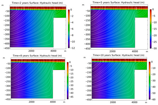
Figure 3.
Temporal variation in hydraulic head (surface plot) and fluid velocity (streamlines) over a 10-year period at years 2, 5, 8, and 10. The results, derived from the Terzaghi compaction model, illustrate the progressive decrease in hydraulic head in the lower confined aquifer along the outlet boundary, driven by continuous pumping. The flow dynamics are represented by arrows indicating fluid velocity vectors, with a noticeable change in direction near the bedrock step.
In the Terzaghi compaction model, the hydraulic head represents subsurface fluid pressure influenced by extraction activities in the lower aquifer. The simulation begins in an equilibrium state with uniform hydraulic head across the domain. Continuous pumping at the outlet boundary reduces the hydraulic head linearly by 60 m over the 10-year period, creating a steady hydraulic gradient. These gradients drives fluid flow from the upper aquifer and surrounding regions toward the pumping well. The presence of a middle confining unit, with a much lower hydraulic conductivity (0.01 m/day) compared to the aquifers (25 m/day), significantly restricts vertical flow. Consequently, most fluid movement occurs horizontally within the highly permeable lower aquifer.
A critical observation from the simulation is the steep hydraulic gradient near the bedrock step, where the sediments thin and hydraulic conductivity decreases. This steep gradient induces a sharp change in both the direction and magnitude of fluid velocities, transitioning from predominantly vertical near the surface to horizontal as the flow approaches the outlet boundary. This behavior highlights the dynamic interplay between hydraulic head variations and fluid flow velocities, especially near geological discontinuities. Such variations in fluid dynamics play a pivotal role in influencing subsurface deformation processes.
Although Terzaghi’s model captures hydraulic head changes and their relationship with vertical compaction, its main limitation is the inability to account for lateral stress redistribution. This makes it less effective in predicting deformation near geological features like the bedrock step, where coupled hydraulic and mechanical interactions are significant. In contrast, Biot’s poroelasticity model overcomes this limitation by incorporating the coupling between fluid flow and mechanical deformation, providing more accurate predictions in complex geological settings. Despite these limitations, Terzaghi’s model remains useful for simulating fluid flow in vertically dominant systems under steady-state pumping conditions.
In Biot’s model, the simulation establishes an equilibrium between gravitational forces and poroelastic forces within approximately 0.2 years, as shown in Figure 4. Beyond this point, variations in the results are solely driven by the changing hydraulic head at the left-hand boundary. To accurately capture the development of the equilibrium state, it is critical to begin the simulation with small time steps, ensuring precise modeling of the initial dynamic interactions. Once equilibrium is reached, larger time steps can be employed to enhance computational efficiency without compromising the accuracy of subsequent results.
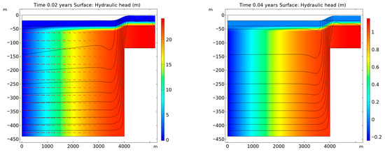
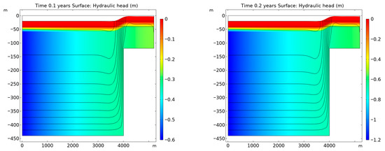
Figure 4.
Simulation results from Biot’s poroelasticity model showing the establishment of equilibrium between gravitational and poroelastic forces within 0.2 years. Following the initial dynamic adjustment period, the model reaches a steady-state with hydraulic head variations at the left-hand boundary remaining the primary driver for subsequent changes in the system.
The robust agreement in hydraulic head predictions between the models highlights the effectiveness of Terzaghi’s simpler approach for large-scale flow problems where elastic deformation and horizontal effects are negligible. However, while Terzaghi’s model successfully captures hydraulic head changes, these results alone are insufficient to fully represent the complexity of deformation processes, particularly near geological discontinuities like the bedrock step. This limitation necessitates a more detailed analysis of vertical and horizontal deformation patterns, which are addressed through Biot’s poroelasticity framework.
The total displacement patterns, as illustrated by the contours and deformed shapes in Figure 5, depict the evolution of lateral deformations compensating for surface elevation changes above the bedrock step. These patterns emphasize the importance of considering both vertical and lateral movements to accurately predict subsurface deformation processes. Terzaghi’s model, while effective for one-dimensional compaction, cannot capture such complex deformation dynamics.
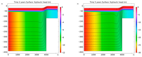
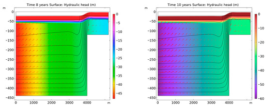
Figure 5.
Comparison of hydraulic head reduction over a 10-year pumping period in the multi-aquifer system, as predicted by Terzaghi’s compaction theory and Biot’s poroelasticity model. The results demonstrate the effects of groundwater extraction on hydraulic head variations, with Biot’s model accounting for lateral strain and coupled feedback mechanisms not captured in Terzaghi’s model.
Biot’s poroelasticity model, on the other hand, builds upon hydraulic head changes predicted by Darcy’s Law by incorporating the coupling between fluid flow and mechanical deformation. As with Terzaghi’s model, the Biot’s model predicts a linear decline of 60 m in hydraulic head over 10 years due to pumping. However, Biot’s model reveals more intricate interactions between hydraulic head changes and deformation processes, as detailed in Figure 5.
In Biot’s model, the poroelastic behavior of sedimentary layers influences the hydraulic head gradient and fluid velocities, coupling fluid flow with solid deformation. Near the bedrock step, abrupt changes in hydraulic head create high-gradient zones, driving fluid flow toward the pumping well. These localized flow patterns, shown by directional arrows in the results, result from the complex feedback between hydraulic gradients and mechanical deformation.
Biot’s model accounts for the compressibility of the porous matrix, which affects fluid flow. As pumping reduces pore pressure, the matrix compresses, altering the hydraulic gradient and further driving fluid movement. This feedback loop between deformation and flow provides a more accurate representation of subsurface processes. After 10 years, the hydraulic head near the basin centerline decreases significantly, while the gradient near the bedrock step remains steep. These results highlight the combined effects of fluid extraction and deformation, offering a more comprehensive understanding than Terzaghi’s model.
Overall, the Biot’s poroelasticity model provides a more nuanced and accurate depiction of hydraulic head changes and their implications for subsurface deformation. By incorporating the interplay between fluid flow and solid deformation, it captures the complex interactions that govern subsurface behavior, particularly in regions with strong hydraulic and mechanical coupling. This makes it a superior tool for analyzing deformation near geological discontinuities and under conditions where dynamic feedback mechanisms are critical.
3.2. Vertical Compaction of Aquifer Sediments: A Terzaghi Compaction Approach
The compaction process described in Equation (7) is a key mechanism in the subsurface behavior of aquifer systems, especially in response to groundwater extraction through pumping. Known as aquifer compaction, this phenomenon results from the relationship between the decline in hydraulic head and the physical properties of the aquifer sediments, such as their compressibility.
Aquifer compaction occurs when the pore pressure in the aquifer decreases due to the removal of groundwater. As water is extracted, the volume of water in the pore spaces reduces, leading to the compression of the sediments themselves. This compression results in a reduction in the vertical thickness of the aquifer, which is quantified as vertical compaction (Δb) in Equation (7). This process directly affects the storage capacity and permeability of the aquifer sediments.
Figure 6 shows the Terzaghi compaction model, which predicts the general compaction trend over time. While it captures the primary compaction behavior, it ignores lateral stress redistribution and the coupled effects of deformation and fluid flow, which are crucial in more complex systems. As a result, Terzaghi’s model yields a smoother, less variable compaction profile, especially near the bedrock step, compared to Biot’s model. Both models predict a maximum compaction of about 0.3 m near the surface, but Terzaghi’s model shows a more uniform compaction gradient across the basin’s depth.
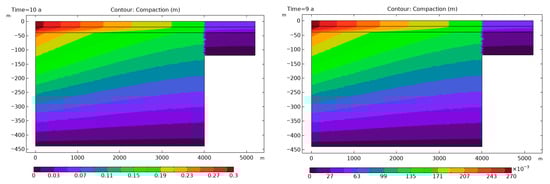
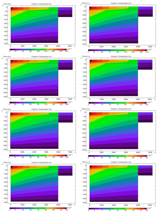
Figure 6.
Contour plots showing vertical compaction of aquifer sediments during 10 years of groundwater pumping.
In contrast to Biot’s poroelasticity model, which considers the interaction between deformation and fluid flow, Terzaghi’s approach treats these processes as independent. This assumption simplifies the compaction process by focusing only on the reduction in pore pressure and the vertical compressibility of the sediments. However, this leads to an over-simplified representation, particularly by not capturing the localized compaction effects near the bedrock step, where deformation and fluid flow typically interact.
The contour plot of vertical compaction in Figure 6 represents the effects of 10 years of groundwater pumping, as predicted by Terzaghi’s model. Key observations include:
- The greatest compaction occurs along the centerline of the basin (at x = 0 m), where the hydraulic head drop is most significant due to pumping. This result aligns with Terzaghi’s theory, which predicts that compaction is directly proportional to the change in hydraulic head.
- Compaction gradually decreases as the distance from the pumping well increases, particularly towards the edges of the basin, where the hydraulic head drop is smaller. This trend illustrates that the effect of pumping-induced compaction diminishes with increased distance from the pumping source.
- The bedrock step (at x > 400 m) creates a boundary that influences both the flow field and compaction. The compaction is more pronounced on the side of the step where the sediments are thicker, due to the higher stress applied to the aquifer materials in this region.
- As the hydraulic head declines by 6 m per year, the rate of compaction increases progressively over time. This continuous reduction in aquifer thickness reflects the sustained nature of the compaction process, with more significant compaction occurring as pumping continues. Over the 10-year period shown in the model, the compaction profiles evolve, with areas near the bedrock step experiencing the most substantial changes in sediment thickness.
As we can see in Figure 6 a clear view of the vertical compaction occurring in response to groundwater extraction, as predicted by Terzaghi’s model. The results are consistent with Terzaghi’s theory, where the compaction process is primarily governed by specific storage and hydraulic head. This model underscores the importance of understanding aquifer compaction for groundwater management and reservoir engineering. It highlights the need to consider the spatial distribution of compaction, the effects of pumping on sediment structure, and the long-term consequences for fluid flow and aquifer integrity.
Understanding these processes is critical for predicting the sustainability of groundwater pumping and ensuring the structural stability of aquifer systems over time. The results from this study provide valuable insights for managing subsurface resources and improving the design of groundwater extraction strategies.
3.3. Dynamic Coupling Between Fluid Flow and Structural Deformation: Insights from Biot’s Poroelastic Model
Figure 7 shows the solid-to-fluid coupling term evaluated at Year 10 as part of the poroelastic analysis. The shading represents the coupling effect, where the squeeze of the porous matrix generates an apparent mass source term. The shading also gives the structure-to-fluid link, which is the negative of the time rate of change in strain (see Equation (1)). This visualization captures the dynamic feedback between fluid flow and structural deformation, a core feature of Biot’s poroelasticity model.
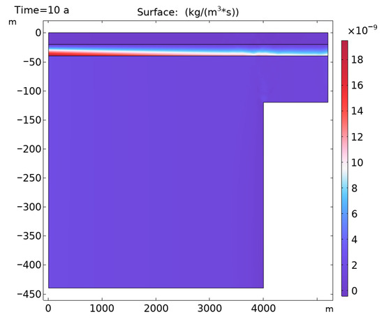
Figure 7.
Coupling effects between fluid flow and deformation, illustrating the feedback loop in the Biot’s model. The figure shows how pore pressure reduction due to fluid extraction leads to further compression of the porous matrix, which, in turn, induces additional fluid movement and alters the hydraulic gradient.
The coupling mechanism illustrated in Figure 7 highlights how reductions in pore pressure, caused by fluid extraction, compress the porous matrix. This compression results in additional fluid redistribution, creating a feedback loop that governs long-term subsurface behavior. The coupling term shown here quantitatively links the deformation of the porous medium to fluid flow, enabling a more accurate and realistic prediction of subsurface processes.
Notably, the effects are most pronounced near the bedrock step, where steep hydraulic gradients induce significant deformation. This deformation further alters the flow field, amplifying the complexity of the interaction. Such coupling effects are critical for capturing realistic subsurface behavior, particularly in regions with significant geological discontinuities.
In contrast, Terzaghi’s consolidation theory lacks this dynamic interdependence, treating fluid flow and deformation as separate processes. While effective for simpler one-dimensional scenarios, Terzaghi’s model cannot capture the two-way interaction evident in Figure 7. Biot’s poroelastic framework, on the other hand, integrates these effects, providing a holistic understanding of subsurface processes and enabling predictions of behavior under conditions of strong hydraulic–mechanical coupling.
Coupling in poromechanics, as described by Biot’s poroelasticity model, fundamentally represents the dynamic interplay between fluid flow and mechanical deformation within porous media [12]. This coupling has profound physical implications, as it links pore pressure changes to structural deformation, creating feedback mechanisms that govern subsurface behavior. When fluid extraction reduces pore pressure, the resulting compression of the porous matrix redistributes stresses, inducing both vertical compaction and lateral deformation [28].
This process, in turn, alters hydraulic gradients and fluid velocities, establishing a feedback loop between deformation and flow. Near geological features, such as bedrock steps, coupling effects become particularly pronounced, driving significant stress redistribution and localized deformation. The interaction also affects permeability and porosity, further influencing fluid migration. This coupling mechanism has practical consequences in predicting subsurface phenomena such as land subsidence, fault activation, and stress evolution, which are critical for applications in groundwater management, reservoir engineering, and infrastructure stability. Neglecting coupling can result in oversimplified models that fail to capture key dynamics, particularly in regions with steep hydraulic gradients or geological discontinuities. Biot’s poroelastic framework thus provides a robust approach to modeling these complex interactions, enabling more accurate and holistic predictions of subsurface processes.
3.4. Horizontal Strain Analysis and Temporal Evolution near Bedrock Discontinuities
Figure 8 presents the horizontal strain at the ground surface, derived from Biot’s poroelasticity analysis for the bedrock step scenario. Additionally, the temporal evolution of strain over 10 years, with results depicted for Years 2, 5, and Year 10 (Table 2). This analysis underscores the distinct advantage of Biot’s framework in capturing lateral deformation, a feature that is absent in Terzaghi’s compaction theory, which assumes purely vertical deformation.
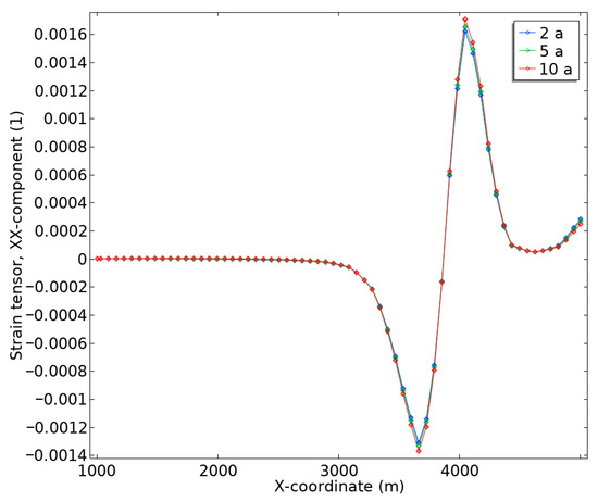
Figure 8.
The temporal progression indicates a steady increase in the magnitude of both compressive and tensile strains over time with 10-year, showing the most pronounced effects. This highlights the importance of accounting for coupled hydro-mechanical interactions when analyzing long-term subsurface deformation.
Table 2.
Biot’s poroelasticity model for the bedrock step scenario.
This numerical model reveals a clear pattern of negative horizontal strain (compression) on the basin side of the bedrock step, attributed to subsidence-driven lateral compaction. Conversely, positive horizontal strain (tension) is observed on the mountain side of the step, corresponding to lengthening due to stress redistribution. These opposing strain responses arise from steep hydraulic gradients and associated deformation near the bedrock discontinuity, demonstrating the two-way coupling of fluid flow and mechanical deformation intrinsic to Biot’s poroelastic model.
Terzaghi’s approach, which treats flow and deformation as independent processes, is unable to predict such lateral strain behavior, thereby limiting its application to more complex geological scenarios like bedrock steps.
The temporal progression depicted in Figure 8 indicates a steady increase in the magnitude of both compressive and tensile strains over time, with Year 10 showing the most pronounced effects. This highlights the importance of accounting for coupled hydro-mechanical interactions when analyzing long-term subsurface deformation. Terzaghi’s approach, which treats flow and deformation as independent processes, is unable to predict such lateral strain behavior, thereby limiting its application to more complex geological scenarios like bedrock steps.
3.5. Von Mises Stress Distribution
Figure 9 presents the Von Mises stress distribution (surface plot), fluid velocity field (streamlines), and displacement (deformation) patterns at (year 0.01, 0.1, 0.2 and year 10), from the poroelastic analysis of the bedrock step scenario. These results, derived from Biot’s poroelasticity theory, provide a detailed visualization of the coupled interactions between stress, fluid flow, and deformation in a subsurface environment characterized by steep hydraulic gradients and geological discontinuities. The vertical axis and displacement are exaggerated for enhanced clarity.
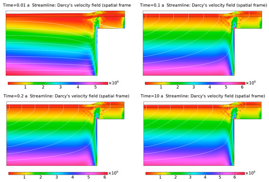
Figure 9.
Von Mises stress distribution, fluid velocity field, and displacement patterns at years of 0.01, 0.1, 0.2 and 10, from poroelastic analysis of the bedrock step scenario. The figure illustrates the coupled interactions between stress, fluid flow, and deformation in a subsurface environment with steep hydraulic gradients and geological discontinuities. The vertical axis and deformation are exaggerated for clarity.
The Von Mises stress distribution reveals significant stress concentrations near the edge of the bedrock step. These concentrations occur in areas where the deformation gradients are steep, indicating where the mechanical compression of the porous matrix is most intense due to fluid extraction. These stress hotspots highlight the regions where the aquifer sediments are undergoing the greatest mechanical strain in response to the declining hydraulic head and the associated reduction in pore space.
The displacement field, as illustrated by the exaggerated deformation patterns, aligns closely with the redistribution of stresses and fluid flow. This visual representation emphasizes the coupled relationship between stress, fluid dynamics, and deformation. The displacement corresponds to the areas where fluid extraction has caused significant changes in the subsurface, particularly near the bedrock step, where the mechanical response is most pronounced.
The streamline patterns represent Darcy’s velocity field, showing fluid movement toward the pumping zone. Near the bedrock step, the streamlines are distorted, reflecting the impact of deformation-induced changes in hydraulic conductivity and pore pressure. This distortion highlights the feedback loop between mechanical deformation and fluid flow, a key feature of Biot’s poroelasticity theory. In this theory, mechanical deformation affects fluid flow, while fluid movement induces additional strain, demonstrating the coupled nature of these processes in the aquifer system. As for numerical results achieved in this study, it is necessary to compare and validate the effectiveness of these new findings relevant to pre-existing research outcomes.
4. Validation
The results of the current study are validated by comparing them to the findings of the referenced study [17]. The validation focuses on three key aspects: hydraulic head distributions, vertical and lateral deformation, and the incorporation of uncertainty due to the spatial variability in material properties.
4.1. Hydraulic Head Distributions
The hydraulic head distributions obtained from Biot’s poroelasticity model in this study show excellent agreement with the probabilistic outcomes of the referenced study. The deviations between the two models are minimal, confirming the accuracy of the Biot’s model in simulating fluid flow dynamics under subsidence conditions. For example, at Years 2, 5, and 10, the hydraulic head reductions predicted by the current study were −3.5 m, −5.7 m, and −9.2 m, respectively, while the referenced study reported values of −3.4 m, −5.6 m, and −9.1 m in Figure 10. The Root Mean Square Error (RMSE) of 0.1 m across these timeframes further validates the model’s robustness. Both models also highlight significant hydraulic gradients near fault zones, which are critical for understanding localized deformation.
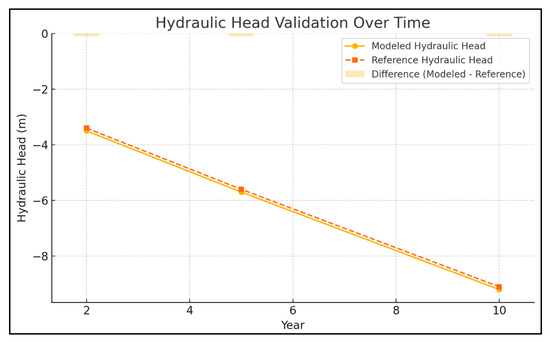
Figure 10.
Comparison of hydraulic head distributions at years 2, 5, and 10 between the Biot’s poroelasticity model and the referenced study.
4.2. Vertical Compaction
The vertical compaction results, primarily modeled using Terzaghi’s consolidation theory, also show a strong correlation with the deterministic trends observed in the referenced study. The current study predicts a maximum compaction of 2.0 m at the pumping center after 10 years of groundwater extraction, closely matching the referenced maximum displacement of 2.1 m Figure 11.
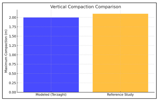
Figure 11.
Vertical compaction results after 10 years of groundwater extraction predicted by Terzaghi’s consolidation theory and the referenced study.
However, while the deterministic approach employed in Terzaghi’s model accurately captures these trends, it does not incorporate the probabilistic variability present in the referenced study. The latter uses a Monte Carlo simulation framework with 500 realizations to account for spatial heterogeneity in material properties, resulting in a wider range of predicted vertical displacements and a ±10% variability around the maximum compaction. This suggests that while the Terzaghi model is effective for capturing the average trends, it has limitations in accounting for the uncertainties observed in real-world scenarios.
4.3. Lateral Deformation
Biot’s poroelasticity model also offers valuable insights into lateral deformation, which is not covered by Terzaghi’s theory. Horizontal strain predictions from the current study show contraction near the bedrock step and tension on the opposite side, with a maximum predicted strain of −0.02. This value is in strong agreement with the reference study, which reported a similar lateral strain magnitude of −0.022 Figure 12.
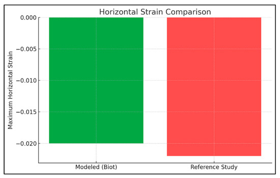
Figure 12.
Lateral deformation predictions from Biot’s poroelasticity model and the referenced study.
Both studies highlight significant strain gradients near the fault zone, indicating localized stress redistribution caused by the coupled processes of fluid flow and deformation. This agreement demonstrates the accuracy of Biot’s model in capturing lateral deformation trends, which are crucial for understanding the geomechanical implications of groundwater extraction near geological features like bedrock steps or faults.
4.4. Deterministic vs. Probabilistic Models
The deterministic approach used in this study assumes homogeneous material properties, simplifying the modeling process and allowing for a more computationally efficient analysis. While this simplification may overlook some of the complexities of spatial variability in material properties, it still captures the dominant deformation and flow dynamics accurately. The strong agreement between the deterministic results from this study and the probabilistic outcomes from the referenced study—particularly in hydraulic head distributions, vertical compaction, and lateral deformation—underscores the robustness and reliability of the models developed here. This agreement highlights the ability of the current study to replicate key deformation mechanisms under steady pumping conditions.
4.5. Practical Implications
Despite the simplifications inherent in the deterministic approach, this study provides a computationally efficient framework for analyzing subsurface deformation and fluid flow. By focusing on deterministic models, it offers a valuable baseline for understanding fundamental subsidence mechanisms. This approach is particularly useful in scenarios where computational resources or extensive data for probabilistic modeling are unavailable. As such, the study positions itself as an effective tool for addressing real-world subsurface challenges, with the flexibility to incorporate probabilistic methods in future work. In this study, it is found that near the bedrock step, the streamlines are distorted, which is useful to indicate the scope of groundwater migration in the real aquifer system. In addition, the results reveal that greater hydraulic gradients near geological discontinuities induce localized deformation and stress redistribution, which can serve as a sign to accurately predict land subsidence and manage groundwater extraction in geologically complex regions.
5. Conclusions
In this study, numerical simulations are systematically conducted to model the hydro-mechanical behavior of a multi-aquifer system, integrating Terzaghi’s compaction theory and Biot’s poroelasticity model. The hydraulic head variations and deformation patterns, including vertical compaction and lateral strain, are examined over a 10-year pumping period. Results indicate that Terzaghi’s model effectively predicts hydraulic head reduction and vertical compaction in vertically dominant systems, while Biot’s model can better capture lateral stress redistribution and dynamic feedback mechanisms between fluid flow and deformation. These findings contribute to the development of robust strategies for groundwater management and subsidence mitigation in geologically complex settings.
Although this investigahtion enhances the critical role of coupled hydro-mechanical modeling in understanding land subsidence and offers actionable insights into approaches innovation, certain model simplifications, such as 2D setup, constant pumping, no pure plasticity, limit its wider engineering applications to some extent. Thus, future model will be developed to achieve 3D visualization, stochastic groundwater injection/ withdrawal, and artifical intelligence-based automatic km-scale modeling. The other future work centers on multi-functional field calibration and validation system, including city-scale modeling, in situ monitoring, satellite-based subsidence characterization in complex city-scale groundwater extraction sites.
Author Contributions
Conceptualization, G.C. and Y.S.; methodology, Y.S.; software, Y.S.; validation, G.C., Q.H. and H.G.; formal analysis, G.C., Q.H. and H.G.; investigation, G.C. and H.G.; resources, Y.S.; data curation, Y.S.; writing—original draft preparation, G.C. and Q.H.; writing—review and editing, Y.S.; visualization, G.C.; supervision, Y.S.; project administration, G.C.; funding acquisition, G.C. All authors have read and agreed to the published version of the manuscript.
Funding
This work is funded by Natural Science Foundation of Fujian Province (Project No.: 2023J01959).
Data Availability Statement
The original contributions presented in this study are included in the article. Further inquiries can be directed to the corresponding authors.
Conflicts of Interest
Author Hongxiu Gong was employed by the company Fujian Academy of Building Research Co., Ltd. The remaining authors declare that the research was conducted in the absence of any commercial or financial relationships that could be construed as a potential conflict of interest.
References
- Johnson, A.I. Land Subsidence Due to Fluid Withdrawal in the United States an Overview. In Land Subsidence Case Studies and Current Research: Proceedings of the Dr. Joseph F. Poland Symposium on Land Subsidence; Borchers, J.W., Ed.; Star Publishing Company: Belmont, CA, USA, 1998; pp. 51–57. [Google Scholar]
- Xue, Y.Q.; Zhang, Y.; Ye, S.J.; Wu, J.C.; Li, Q.F. Land Subsidence in China. Environ. Geol. 2005, 48, 713–720. [Google Scholar] [CrossRef]
- Lin, Z.; Huili, G.; Xiaojuan, L.; Chaofan, Z.; Miao, Y.; Haigang, W.; Ke, Z.; Miaomiao, H. Research Progress and Prospect of Land Subsidence. Hydrogeol. Eng. Geol. 2024, 51, 167–177. [Google Scholar]
- Guo-ying, P.; Fu-ping, Z.; Yan-xiang, J.; Yun, L. Applying Gray Association Analytical Method to Identify Pump Water Which Result in Land Subsidence. J. Henan Polytech. Univ. (Nat. Sci.) 2006, 25, 18–21. [Google Scholar] [CrossRef]
- Corapcioglu, M.Y.; Bear, J. Land Subsidence—B. A Regional Mathematical Model for Land Subsidence Due to Pumping; Springer: Dordrecht, The Netherlands, 1984; ISBN 9789400961777. [Google Scholar]
- Budhu, M.; Adiyaman, I.B. Mechanics of Land Subsidence Due to Groundwater Pumping. Int. J. Numer. Anal. Methods Geomech. 2010, 34, 1459–1478. [Google Scholar] [CrossRef]
- Shen, S.-L.; Xu, Y.-S. Numerical Evaluation of Land Subsidence Induced by Groundwater Pumping in Shanghai. Can. Geotech. J. 2011, 48, 1378–1392. [Google Scholar] [CrossRef]
- Yeh, C.L.; Lo, W.C.; Lin, C.W.; Ding, C.F. Influence of Pore Water Pressure Change on Consolidation Behavior of Saturated Poroelastic Medium. Proc. Int. Assoc. Hydrol. Sci. 2020, 382, 375–379. [Google Scholar] [CrossRef]
- Peilian, R.; Shaoda, L.; Keren, D.; Xiaoxia, Y.; Sen, Z.; Zhongxin, R. SBAS-InSAR Monitoring and Analysis of Land Subsidence in Xiongan New Area from 2017 to 2019. J. Henan Polytech. Univ. (Nat. Sci.) 2022, 41, 66–73. [Google Scholar] [CrossRef]
- Ran, M.; Yanan, J.; Lu, L.; Qiang, X.; Weile, L.; Huiyuan, L. Comparative Study of Dual-Polarized Sentinel-1 Data in Urban Subsidence Monitoring. J. Henan Polytech. Univ. (Nat. Sci.) 2024, 43, 77–86. [Google Scholar] [CrossRef]
- Terzaghi, C. Principles of Soil Mechanics: V-Physical Differences between Sand and Clay. Eng. News Rec. 1925, 96, 912–915. [Google Scholar]
- Biot, M.A. General Theory of Three-Dimensional Consolidation. J. Appl. Phys. 1941, 12, 155–164. [Google Scholar] [CrossRef]
- Huang, J.; Diao, Y.; Zheng, G.; Su, Y.; Wang, M.; Pan, W.; Chen, H. Horizontal Deformation Efficiency of a Pile Controlled by the Capsuled Expansion Technique: A Field Trial and Numerical Analysis. Int. J. Geomech. 2024, 24, 04023262. [Google Scholar] [CrossRef]
- Ammons, B.A.; Vable, M. Boundary Element Analysis of Cracks. Int. J. Solids Struct. 1996, 33, 1853–1865. [Google Scholar] [CrossRef]
- Xu, Y.S.; Shen, S.L.; Cai, Z.Y.; Zhou, G.Y. The State of Land Subsidence and Prediction Approaches Due to Groundwater Withdrawal in China. Nat. Hazards 2008, 45, 123–135. [Google Scholar] [CrossRef]
- Ferronato, M.; Gazzola, L.; Castelletto, N.; Teatini, P.; Zhu, L. A Coupled Mixed Finite Element Biot Model for Land Subsidence Prediction in the Beijing Area. In Poromechanics 2017—Proceedings of the 6th Biot Conference on Poromechanics; American Society of Civil Engineers: Reston, VA, USA, 2017; pp. 182–189. [Google Scholar] [CrossRef]
- Deng, S.; Yang, H.; Chen, X.; Wei, X. Probabilistic Analysis of Land Subsidence Due to Pumping by Biot Poroelasticity and Random Field Theory. J. Eng. Appl. Sci. 2022, 69, 18. [Google Scholar] [CrossRef]
- Tsai, T.L.; Chang, K.C.; Huang, L.H. Body Force Effect on Consolidation of Porous Elastic Media Due to Pumping. J. Chin. Inst. Eng. 2006, 29, 75–82. [Google Scholar] [CrossRef]
- Tseng, C.-M.; Tsai, T.-L.; Huang, L.-H. Effects of Body Force on Transient Poroelastic Consolidation Due to Groundwater Pumping. Environ. Geol. 2008, 54, 1507–1516. [Google Scholar] [CrossRef]
- Chen, Z.; Ni, P.; Chen, Y.; Mei, G.; Chen, Z. Plane-Strain Consolidation Theory with Distributed Drainage Boundary. Acta Geotech. 2020, 15, 489–508. [Google Scholar] [CrossRef]
- Wang, L.; Zhang, Y. Interpreting Correlations in Stress-Dependent Permeability, Porosity, and Compressibility of Rocks: A Viewpoint from Finite Strain Theory. Int. J. Numer. Anal. Methods Geomech. 2024, 48, 2000–2019. [Google Scholar] [CrossRef]
- Leake, S.; Hsieh, P.A. Simulation of Deformation of Sediments from Decline of Ground-Water Levels in an Aquifer Underlain by a Bedrock Step. In Proceedings of the US Geological Survey Subsidence Interest Group Conference, Las Vegas, NV, USA, 14–16 February 1995; p. 10. [Google Scholar]
- COMSOL BV; COMSOL OY. COMSOL Multiphysics User’s Guide; COMSOL AB: Stockholm, Sweden, 1998. [Google Scholar]
- Tabarroki, M.; Ching, J.Y. Discretization Error in the Random Finite Element Method for Spatially Variable Undrained Shear Strength. Comput. Geotech. 2019, 105, 183–194. [Google Scholar] [CrossRef]
- Shen, Z.; Jin, D.; Pan, Q.; Yang, H.; Chian, S.C. Effect of Soil Spatial Variability on Failure Mechanisms and Undrained Capacities of Strip Foundations under Uniaxial Loading. Comput. Geotech. 2021, 139, 104387. [Google Scholar] [CrossRef]
- Biot, M.A. Theory of Elasticity and Consolidation for a Porous Anisotropic Solid. J. Appl. Phys. 1955, 26, 182–185. [Google Scholar] [CrossRef]
- Wang, H. Theory of Linear Poroelasticity with Applications to Geomechanics and Hydrogeology; Princeton University Press: Princeton, NJ, USA, 2000; Volume 2. [Google Scholar]
- Li, L.; Tan, J.; Wood, D.A.; Zhao, Z.; Becker, D.; Lyu, Q.; Shu, B.; Cheng, H. A Review of the Current Status of Induced Seismicity Monitoring for Hydraulic Fracturing in Unconventional Tight Oil and Gas Reservoirs. Fuel 2019, 242, 195–210. [Google Scholar] [CrossRef]
Disclaimer/Publisher’s Note: The statements, opinions and data contained in all publications are solely those of the individual author(s) and contributor(s) and not of MDPI and/or the editor(s). MDPI and/or the editor(s) disclaim responsibility for any injury to people or property resulting from any ideas, methods, instructions or products referred to in the content. |
© 2025 by the authors. Licensee MDPI, Basel, Switzerland. This article is an open access article distributed under the terms and conditions of the Creative Commons Attribution (CC BY) license (https://creativecommons.org/licenses/by/4.0/).