Abstract
To study the mechanical properties and displacement evolution of rock masses near coal-seam normal faults under mining disturbances; this paper utilizes fiber optic monitoring and distributed strain measurement techniques to achieve the fine monitoring of the entire process of stress–displacement–strain during mining. The experimental design adopts a stepwise mining approach to systematically reproduce the evolution of fault formation; slip; and instability. The results show that the formation of normal faults can be divided into five stages: compressive deformation; initiation; propagation; slip; and stabilization. The strength of the fault plane is significantly influenced by the dip angle. As the dip angle increases from 30° to 70°, the peak strength decreases by 23%, and the failure mode transitions from tensile failure to shear failure. Under mining disturbances, the stress field in the overlying rock shifts from concentration to dispersion, with a stress mutation zone appearing in the fault-adjacent area. During unloading, vertical stress decreases by 45%, followed by a rebound of 10% as mining progresses. The rock layers above the goaf show significant subsidence, with the maximum vertical displacement reaching 150 mm. The displacement between the hanging wall and footwall differs, with the maximum horizontal displacement reaching 78 mm. The force chain distribution evolves from being dominated by compressive stress to a compressive–tensile stress coupling state. The fault zone eventually enters a stress polarization state and tends toward instability. A large non-uniform high-speed zone forms at the fault cutting point in the velocity field, revealing the mechanisms of fault instability and the initiation of dynamic disasters. These experimental results provide a quantitative understanding of the multi-physics coupling evolution characteristics of coal-seam normal faults under mining disturbances. The findings offer theoretical insights into the instability of coal-seam normal faults and the mechanisms behind the initiation of dynamic disasters.
1. Introduction
Coal plays a fundamental role in China’s energy security system, especially in the context of the rapid growth in electricity demand driven by industrialization and urbanization. However, prolonged high-intensity mining has led some mining areas to near depletion, with significant declines in coal reserves. Due to China’s resource endowment characteristics and the requirements of regional economic development, the extraction of high-quality coal resources in fault zones is urgently needed. However, the formation of faults disrupts the continuity and integrity of the strata, resulting in low rock strength and large deformations in these areas. The displacement and stress fields in the vicinity of these faults undergo significant changes, accumulating a large amount of residual energy and tectonic stress, making them important factors in triggering fault-type mining disasters [1,2,3,4]. Among the many types of fault structures, normal faults are the most common in coal mining areas. With large displacement and extensive fault zones, they exert a stronger control over mining space and stress redistribution, making dynamic disaster risks in normal fault zones particularly prominent. Furthermore, mining disturbances further alter the mechanical properties of the rock mass and increase the risk of fault slip, leading to fault reactivation. Therefore, a deep understanding of the formation and evolution mechanisms of faults, and their role in controlling mining disasters—especially clarifying the response characteristics and disaster processes of normal faults under mining disturbance—is key to effective coal mine disaster prevention and control [5,6,7,8].
From a seismological perspective, friction and shear in fault zones play a dominant role in dynamic disasters. When the shear stress on the shear plane reaches a critical value, relative displacement occurs between the rock masses on either side of the shear plane, leading to fault formation [9,10,11,12,13,14]. Many scholars have delved into the mechanisms of rock fracture, the characteristics of frictional sliding, and the influence of stress states on fault formation [15,16,17,18]. Wang et al. [19] investigated the mechanical properties, strength characteristics, and energy responses of coal–rock composites under different loading rates. Wang et al. [20] used numerical simulations to study the initiation and propagation of slip on the contact interface and analyzed the changes in the contact interface stress field. The study found that, as shear load increases, the slip gradually extends from regions with low friction strength to areas with higher friction strength. Guo et al. [21] studied the effects of different dip angle interfaces on the deformation and failure of coal–rock composites, with results showing that when the dip angle exceeds 45–50°, there is an inverse relationship between the work done by external forces and the yield stress, as well as between elastic strain energy. The failure mode of the coal–rock composite gradually transitions from shear deformation to interface slip failure.
Meng et al. [22] demonstrated that the single weak plane theory can effectively predict the stress reactivation of faults, while changes in acoustic emission signals and deformation rates can serve as precursors to dynamic fault slip. Zhang et al. [23] found that the type of parent rock, initial normal stress, and displacement loading rate are the main factors affecting fault slip modes, with changes in slip modes for different parent rocks closely related to mineral composition and microstructure. Fang et al. [24] conducted uniaxial compression tests on rock masses along fault planes and found that the dip angle of the fault plane under low confining pressure determines the failure mode of the rock mass, with the influence of the fault plane weakening as the confining pressure increases. Thomas et al. [25] studied fault slip mechanisms during fluid fracturing and revealed how mechanisms such as flash heating and softening can trigger fault instability, leading to the formation of newly generated fault slip fractures. While the motivation to combine shear tests with physical simulation is evident, there is limited research providing a quantitative understanding of fault behavior under mining disturbances. Previous studies on fault formation and reactivation under stress have overlooked the coupling of multiple physical fields, including stress, strain, displacement, and velocity [26,27]. This study, however, provides quantitative insights into the multi-physics interactions within the fault zone under initial tectonic stress, offering a more comprehensive perspective for understanding fault dynamics and activation. The aforementioned studies mainly focus on conditions under single stress, without considering the impact of time-varying mining disturbances on fault zone dynamics and multi-physics interactions.
Under the dual influence of mining and tectonic stress fields, coal seam mining in fault zones is prone to fault instability, which can lead to various dynamic disasters in coal mines [28,29]. Cai et al. [30] proposed two fault activation models, “FRMSS” and “FRSDS,” and validated them through experiments, numerical simulations, and field microseismic monitoring. Wang et al. [31] found that the influence of faults on the mining face first appears in the lower and middle parts of the coal seam and gradually extends to the top as the working face advances, showing a clear upward effect. Li et al. [32] developed a three-dimensional numerical model to analyze fault damage and coseismic slip caused by mining activities, emphasizing the triggering role of reduced normal stress in fault reactivation, providing new insights for improving deep mining safety and stability. Wang et al. [33] further revealed that the coupling of mining-induced stress and high static stress fault coal pillars can trigger dynamic disasters, with fault slip playing a key role in this process. Wang [34] et al. showed that the depth of the mine, fault geometry, and the physical-mechanical properties of faults significantly affect fault displacement evolution. In areas with greater depth or more complex fault characteristics, changes in fault displacement are more intense. However, many of these studies use numerical models based on assumptions about fault geometry and material properties, which may not fully reflect the dynamic and heterogeneous characteristics of actual fault zones. Babets et al. [35] conducted a multi-factor analysis of fault stability under mining disturbances, studying the impact of mining-induced stress and mining operations on fault behavior and proposing important stability assessment methods. These provide a strong theoretical foundation for further disaster prevention and mining safety control. Li et al. [36] found that fault reactivation caused by mining activities is closely related to the stress ratio (k), where changes in tensile and compressive stress significantly affect fault stability, potentially triggering seismic slip. However, many of these studies rely on numerical models that are based on assumptions regarding fault geometry and material properties, which cannot fully capture the dynamic and heterogeneous characteristics of actual fault zones.
In summary, while existing research has made significant progress in revealing the formation mechanisms and slip characteristics of faults, there is still a lack of systematic understanding of the stress response mechanisms and evolutionary patterns of coal-seam normal faults under mining disturbances. In particular, research on the coupling relationship between the mechanical properties of fault planes, the fault slip process, and the evolution of the overlying rock stress field under different fault dip angles is insufficient. Based on this, this study, under the context of native normal fault structures, first reconstructs the fault formation process and its initial tectonic stress field distribution using physical simulation with similar materials. Subsequently, the study simulates the gradual advancement of the working face along the coal seam, capturing the spatiotemporal evolution of multi-parameters such as stress, strain, displacement, and velocity within the fault zone. It systematically explores scientific issues, such as the distribution law of the initial tectonic stress field during fault formation, the mining-induced rock mass response characteristics under initial tectonic stress, and the mining fault slip instability and disaster mechanisms. This provides a new perspective and analytical framework for a deeper understanding of fault activation mechanisms and the prediction and prevention of fault-type disasters in coal mines.
2. Experimental Design and the Process of Normal Fault Formation
2.1. Experimental Design
In this study, a physical simulation system was used to model the evolution of faults and the response of rock masses to mining. This system has the function of an adjustable inclination angle. The system includes vertical and horizontal loading devices, and its transparent front plate can be used to observe the deformation of the rock layer surface. This study employs the geometric similarity ratio and the similarity ratio of bulk density . Based on the principle of similarity of continuous media, the similarity relationships for stress, modulus, and strength can be obtained: , Here, “σ” represents stress and “E” represents the elastic modulus; they have an elastic modulus-to-stress intensity ratio of 1:450. The actual burial depth of the coal seam is 330 m. The 201.6 m of rock layer that could not be simulated in the upper part is compensated by applying the compensation load qm = 0.11 MPa through the mathematical expression (1).
“q” represents the actual load on the upper part of the coal seam, Pa; “qm” is the load to be applied in the similar model test, MPa; “ρ” is the density of the rock layer, taken as 2500 Kg/m3; and “h” is the thickness of the un-laid overlying rock layer, m.
2.2. Physical Model Materials and Proportions
Based on the above ratios, the parameters of the original rock layer were converted. Using sand, calcium carbonate, gypsum, and water as the base materials, multiple sets of uniaxial compression tests were conducted to verify the peak strength and elastic modulus of the model materials. Make it meet the requirements ,. The overall size of the model is 160 cm × 60 cm × 30 cm. The dip angle of the fault was set at 70°. Table 1 lists the thickness, density, and strength parameters of various rock units, as well as the corresponding material usage.

Table 1.
Mechanical parameters of each rock stratum and material usage.
The strata in the mine are multilayered, but the number of rock types is relatively small. Similar types of rock layers were simplified to have the same mechanical parameters, resulting in the physical and mechanical parameters for different rock layers, as shown in Table 2.
Table 2.
Physical and mechanical parameters of rock strata.
Based on the physical and mechanical parameters of the actual rock layers, the meso-mechanical parameters of the rock layers were calibrated. The calibrated meso-parameters of the rock layers are detailed in Table 3. The parallel bond model has the capability to simulate the connecting behavior between particles through cementing substances. This model allows contact forces to be transmitted between particles, thereby enabling a more realistic representation of material deformation and failure during the loading process. Therefore, the parallel bond model was chosen for this simulation.
Table 3.
Mesoscopic parameters of rock strata.
2.3. Materials and Monitoring System
The construction of the model followed a step-by-step compaction method [33]. For each layer, the required amounts of sand, calcium carbonate, gypsum, and water were accurately weighed, thoroughly mixed, and then poured into the model. The material was then evenly spread and compacted to the desired thickness. A thin mica powder layer was applied between each sedimentary layer to simulate bedding planes or potential sliding surfaces, allowing for separation. This process was repeated to replicate the complete sedimentation sequence, as illustrated in Figure 1a.
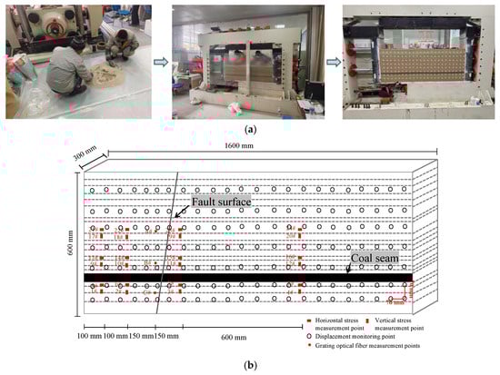
Figure 1.
Layout of monitoring points and preparation of test: (a) preparation of test; (b) layout of monitoring points.
As shown in Figure 1b, the monitoring system includes 184 displacement measurement points and 24 stress sensors. The sensors were mainly deployed in the fault zone and its adjacent areas to capture the stress evolution characteristics under mining disturbance. The simulated mining operation started at a position 90 cm above the fault on the handing wall and ended at a position 10 cm below the fault on footwall. Each coal layer mined was 5 cm in length, representing the actual coal layer mining length of 15 m; the total mining length was 80 cm, representing the actual total coal layer mining length of 240 m. After each mining was completed, it was left to stand for 1 h to ensure the redistribution of the stress field and displacement field. At the same time, optical fiber sensing system and the distributed DH3816 static strain acquisition unit were used to monitor the coordinated changes in stress, strain, and displacement in real time. Data processing was carried out using Surfer 29 software to visualize and dynamically analyze the stress field and displacement field, and a numerical model was constructed using the particle flow software to simulate the formation of faults and the response of the rock mass to mining disturbance. The overall experimental system cannot only reproduce the formation and evolution process of a normal fault but also reveal the multi-physics field coupling effect under mining disturbance.
2.4. Evolution Process of Normal Fault Formation
The formation of a normal fault is a complex geological evolution process. Based on the characteristics presented by the experiments, it is divided into five stages: the stage of rock layer compression deformation, the stage of fault initiation, the stage of fault expansion, the stage of fault slip, and the final stable stage. The formation process of a normal fault is shown in Figure 2. In the initial stage, the model rock layer structure was initially intact and there are no obvious macroscopic fractures. Under the action of compensatory load, the overlying rock layer undergoes overall compression deformation, and the internal stress gradually accumulates. When the stress in a local area reaches the strength limit of the rock mass, cracks first initiate at a large inclination angle from the middle and expand to the upper and lower sides, entering the “fault initiation stage”. During this stage, the deformation of the upper and lower parts of the rock layer is obvious, while the cracks in the middle close quickly, reflecting the dynamic evolution process of local shear stress concentration. As the loading test continues, the stress further spreads to the surrounding areas, the non-uniform deformation of the rock layer intensifies, and it enters the “fault expansion stage”. At this time, the loading on the left side of the model generates a significant lateral compression effect, causing the fault plane to expand longitudinally, and the local displacement gap increases; the rock layer shows S-shaped bending folds, and the shear compression effect causes the range of the fault zone to continuously expand, and the fracture area gradually forms and connects. After the formation of the fault, the rock properties and stress state jointly affect its slip response path. In the “fault slip stage”, the fault undergoes displacement deformation along the slip interface, and when the inclination angle reaches above 70°, the coal seam shows significant up-down displacement, forming a typical normal fault structure. The morphology of the fault in this stage is controlled by the mechanical heterogeneity of the rock layer; although the overall trend has a local deflection, it remains continuous and stable. In the final stage, the stress field of the system tends to be balanced, the fractures gradually close, and the morphology of the fault structure tends to be stable. The latter slip caused by the redistribution of stress tends to be alleviated, and the fault enters the compaction consolidation stage. The experimental observations also show that the deformation strength of the rock mass around the fault is much greater than that in the area far from the fault, especially footwall, which is subjected to more severe shear stress, showing more obvious slip and displacement responses.
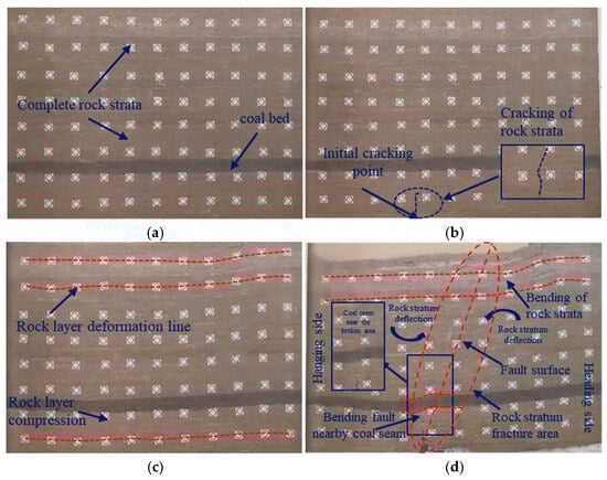
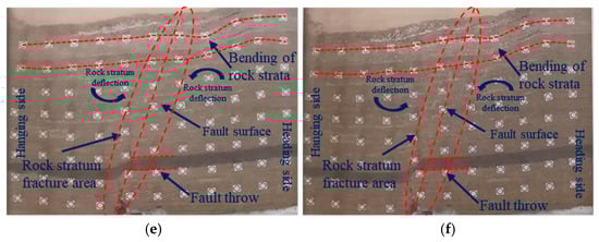
Figure 2.
Formation process of a normal fault: (a) initial state; (b) fault initiation; (c) fracture propagation; (d) 50% of final drop; (e) 75% of final drop; (f) final stable fault structure.
To further reveal the response mechanism of mining-induced disturbance after the formation of faults, this paper conducted an underground coal mining experiment based on the model of a normal fault formation. By applying excavation disturbance loads, it simulated the dynamic evolution process of stress transmission and structural failure during actual mining, and focused on analyzing the migration of stress concentration areas near the fault plane, the expansion behavior of shear bands, and the variation characteristics of the displacement field. This part of the experiment provided key data support for the subsequent quantitative revelation of the coupling effect between faults and mining.
3. Law of Seismic Response Caused by Mining Activities on Normal Faults
3.1. Deformation and Failure Process of Rock Layers Under Footwall of Faults
In contrast to the importance of support structures and coal seam thickness for roadway deformation as highlighted by Babets et al. [32], the results of this study further demonstrate that when the fault is within the mining disturbance range, the fault-rock mass coupling mechanism becomes the dominant factor. This suggests that in rock mass design and safety assessments, both support parameters and coal seam geometry should be considered, and the fault structure and its interaction with the mining stress field should be incorporated.
Figure 3 shows the structural response characteristics of the rock strata at the working face relative to the fault during the mining process in the direction of the fault’s lower plate. The evolution of the normal fault can be divided into five stages: rock layer compression deformation, cracking, expansion, sliding, and stability. The cracking stage is driven by local shear stress concentration, the expansion stage shows “S-shaped” curvature and shear-press coupling effect, and the sliding stage shows significant lateral movement between the upper and lower plates when α ≥ 70° and gradually stabilizes. The mining test shows that as the working face advances from the handing wall side by 90 cm towards the fault, the overlying strata transition from intact to fractured: at 70 − 55 cm, the fracture initiation occurs and an early collapse zone is formed; at 45 − 35 cm, it enters the disturbed core area, the roof becomes suspended and the plastic bending intensifies; at 20 − 10 cm, the structural stress and mining-induced stress are strongly coupled, the roof is overall fragmented, and the collapse rapidly expands, and the fault-mining enters the strong response stage. In the displacement field, vertical subsidence is mainly located above the mined area, and horizontal displacement is enhanced in the area close to the fault on footwall; in the stress field, after the vertical stress is rapidly unloaded, rebound occurs, the horizontal stress overall decays, while the drop amplitude within the fault zone is relatively smaller.
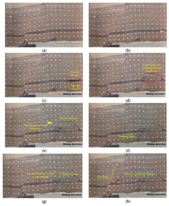
Figure 3.
Overburden structure during mining towards the fault direction at the working face of the footwall: (a) Unmined rock mass; (b) 80 cm from the fault; (c) 70 cm from the fault; (d) 55 cm from the fault; (e) 45 cm from the fault; (f) 35 cm from the fault; (g) 20 cm from the fault; (h) 10 cm from the fault.
3.2. Evolution Characteristics of the Subsidence Displacement Field of Footwall After the Formation of a Normal Fault
To quantitatively analyze the deformation evolution characteristics of the overlying strata during the back mining process of the fault bottom, the displacement monitoring data were visually processed using the Surfer software, and the vertical and horizontal displacement field distribution maps of the rock layers at different time periods were obtained, as shown in Figure 4. In the initial stage of mining, the overall structure of the overlying strata remained stable, and the displacement variation in the rock layers was relatively small. During this stage, the vertical displacement mainly occurred in the mining void area and the local area above the fault, showing a slight subsidence trend; while the horizontal displacement was limited to the vicinity of the fault bottom, with an extremely small amplitude, indicating that the mining disturbance had not significantly affected the fault structure, and the regional stress field remained in its original state. When the working face advanced to 55 cm away from the fault, the coal mining−induced energy release occurred, causing the stress distribution of the surrounding rock to change. The rock layer above the mining void began to show significant subsidence, forming a typical collapse area, with a significant increase in vertical displacement, especially above the mining void. In contrast, the horizontal displacement remained at a relatively low level and was more dispersed, reflecting that the rock mass mainly underwent vertical deformation caused by gravity during this stage, and the lateral shear was not significant. As the working face further advanced to the vicinity of the fault, the fault structure entered the disturbance core area. At this time, the collapse range of the roof significantly expanded, the overall stability of the rock mass decreased, and due to the weakened supporting capacity, the vertical displacement in some areas actually decreased. At the same time, the rock mass showed a weak horizontal displacement along the working-face advance direction, with a concentrated spatial distribution in the bottom part of the fault zone. This phenomenon indicates that the fault area has undergone significant stress redistribution and slip response, with the displacement evolution trend evolving from unidirectional subsidence to multi-directional coupling, and possessing a complex mechanical regulation mechanism.
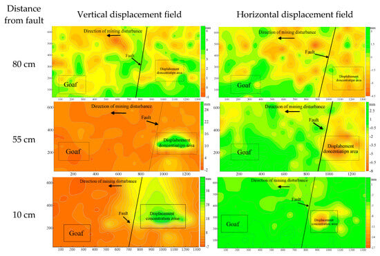
Figure 4.
Displacement field of the coal mining face in the lower strata.
3.3. Internal Strain Within the Fault Plane During the Down-Dip Mining Process
During the mining process, the strain variations within the fault plane are not only caused by mining disturbances but are also closely related to stress redistribution, fault slip, and the elastic and plastic deformation of the rock mass. The stress redistribution induced by mining causes significant stress concentration near the fault, resulting in more pronounced strain changes in the localized area. Especially in the fault−activated zone, as slip occurs, relative displacement of the rock mass happens, leading to a larger strain amplitude in that region. Additionally, the combined action of shear and tensile stress on the fault plane further influences the strain evolution process. Strain responses vary at different locations, with areas closer to the fault being more influenced by mining disturbances, exhibiting more significant strain changes. This reflects the complex interaction between mining disturbances and fault slip.
During the mining process of the lower coal seam, the vertical strain within the fault plane shows significant temporal differences, as shown in Figure 5. The A measurement point, which is located at a shallow depth and close to the mining area, experienced the earliest and most significant changes, displaying the largest amplitude; the B measurement point’s response was slightly delayed and had a smaller amplitude; the C measurement point showed the latest and weakest strain changes. This difference mainly results from the adjustment of the rock mass stress distribution caused by mining disturbances. As the working face advances, the vertical strain at each measurement point fluctuates briefly and then gradually stabilizes, and the rock mass gradually reaches a new stress equilibrium. However, when the working face approaches the fault zone further, local stress concentration rapidly increases, and the vertical strain at the three measurement points again experiences intense fluctuations, with point A being the most significant. This sudden increase in strain reflects the coupling effect of fault slip and stress concentration, marking the critical state of the fault entering an unstable failure. Thus, the rock mass close to the fault at the shallow depth is more susceptible to the excitation of mining disturbances, has a more intense strain response, and therefore has higher disaster sensitivity.
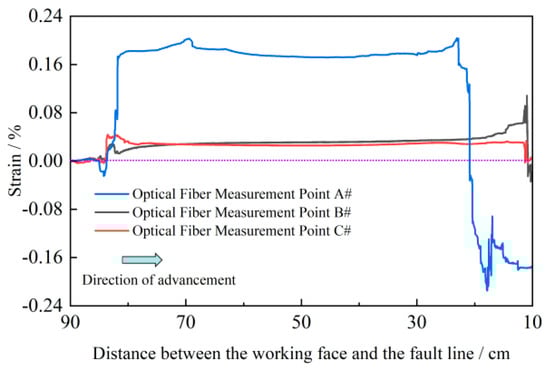
Figure 5.
Vertical strain on the fault plane during footwall mining monitored by optical fiber.
3.4. Stress Variation Pattern of the Overlying Rock Layer After the Formation of a Normal Fault
Figure 6 shows the evolution patterns of vertical and horizontal stresses recorded at different monitoring points during the coal mining process on footwall after the formation of the normal fault. The test results indicate that as the mining disturbance gradually approaches the fault, the rock stress field undergoes significant restructuring, and the response characteristics of different stress components vary significantly. Overall, the variation range of vertical stress is significantly greater than that of horizontal stress, and it is more sensitive to mining disturbance. When the mining disturbance approaches the fault area, the overlying rock’s bearing capacity weakens, and the vertical stress drops rapidly. Subsequently, due to roof collapse and structural adjustment, there is a certain degree of rebound. At the monitoring points near the fault on the floor, the vertical stress drops particularly sharply, demonstrating the unloading and failure characteristics of deep rock masses under mining disturbance; while at the monitoring points near the fault on the roof, during the initial stage of mining, due to structural compression, there is a brief stress increase, and then it quickly enters the downward stage.
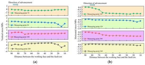
Figure 6.
Stress variations during mining at the footwall of a normal fault: (a) vertical stress; (b) horizontal stress.
To better understand the evolution process of normal faults under mining disturbances, this study employs the PFC2D 5.0 software to perform two-dimensional particle flow numerical simulations, based on the same engineering and geological background as the physical simulation. The numerical model is established according to the prototype scale, with a model range of approximately 480 m × 180 m. The coal seam depth is about 330 m, and the fault dip angle is 70°. The spatial arrangement of the coal seam, fault, and their surrounding rocks is consistent with the actual mining geological conditions and the physical similarity model.
The material properties used in the simulation were calibrated based on experimental data. These properties include the elastic modulus, Poisson’s ratio, cohesion, and friction angle of each rock layer. Specifically, the model uses rock strength and elastic modulus obtained from uniaxial compression tests, ensuring that the material properties align with experimental data, thus guaranteeing the reliability of the simulation results. In the simulation, we used a step-by-step mining approach, extracting 5 cm thick layers of coal at each step to simulate the gradual disturbance of the actual mining process. The loading conditions at each step reflect the progression of mining and track the evolution of the stress field, displacement field, and fault slip behavior in the rock layers. The numerical simulation results were compared with physical experimental data to validate the model’s accuracy. The simulation successfully reproduced the fault evolution process, including initial compressive deformation, fault initiation and propagation, and the final stabilization phase. The stress redistribution and fault slip patterns in the simulation were consistent with the behavior observed in the experiments, demonstrating the effectiveness of the numerical model.
3.5. The Impact of Underground Mining on Rock Mass Stress in Fault Zones
The stress field of the overlying rock mass underwent a transition from concentration to relaxation, with stress mutation regions appearing in the areas adjacent to the fault. We believe that the observed polarization of the stress field prior to instability is not merely a local response to mining disturbance, but rather an emergent characteristic of multi-scale energy redistribution within the overlying layers. This redistribution occurs as energy induced by mining propagates through the fault zone and surrounding rock mass, leading to the reorganization of the stress and displacement fields. As mining disturbance progresses, the interaction of energy accumulated at different scales results in the observed stress concentration and polarization phenomena, signaling fault instability and dynamic failure.
Figure 7 shows the entire process of the structural evolution of the overlying strata as the working face advances from far to near towards the fault. From the initial excavation stage to the point where it cuts through the fault, six different working conditions can be observed. It can be seen that the overlying strata gradually transition from overall integrity to crack expansion, large-scale collapse, and fault displacement. In the initial stage of mining, the overall structure of the overlying strata was relatively stable, showing only slight bending deformation, and the fault zone had not yet been significantly disturbed. When the working face advanced to 135 m from the fault, the roof layer separated, and initial collapse occurred. The cracks gradually developed towards the fault direction. Continuing to advance to 90 m, the cracks expanded rapidly, the roof layer produced large-scale bending and suspension phenomena, and the adjacent area of the fault zone began to enter a strong response stage. When the working face advanced to 45 m, the upper rock layer sagged significantly, the fault zone cracks were connected and lost stability, and the structural integrity was significantly weakened. Finally, when the working face cut through the fault, the roof layer experienced large-scale collapse, the fault zone as a whole shifted, and the handing wall sagged while footwall locally uplifted, indicating that the coupling effect of mining disturbance and structural stress reached the strongest stage. This series of evolution processes directly reveal the coupling relationship between the deformation of the overlying strata and the response of the fault: as the working face gradually approaches the fault, mining disturbance not only induces roof collapse and crack connection, but also significantly enhances the risk of fault displacement, providing a structural basis for the non-uniform distribution of the stress field, displacement field, and velocity field in the future.
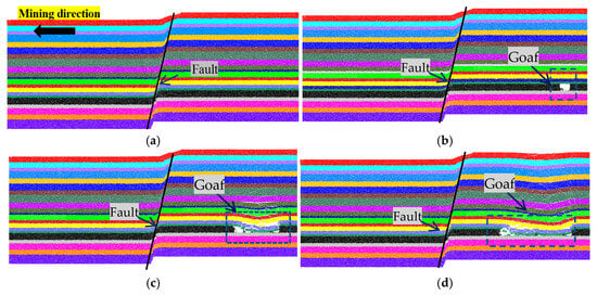
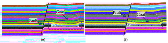
Figure 7.
Mining towards the fault direction at the footwall working face: (a) unexcavated rock strata; (b) 195 m from the fault; (c) 135 m from the fault; (d) 90 m from the fault; (e) 45 m from the fault; (f) 0 m from the fault.
3.6. The Impact of Up-And-Down Mining on Rock Mass Displacement in Fault Zones
Figure 8 shows the distribution characteristics of the horizontal and vertical displacement fields at different stages during the progressive advancement of the lower working face towards the fault. Overall, as the working face gradually approaches the fault, the displacement fields exhibit an evolution trend of expanding from a local scale to a larger area, and the displacement anomalies are most significant in the vicinity of the fault. At a distance of 195 m from the fault, the overall horizontal and vertical displacements are relatively small, mainly concentrated above the mined-out area, and no significant response has occurred in the fault zone yet. When advancing to 135 m, the mined-out area expands, the horizontal displacement significantly increases and extends towards the fault side, while the vertical displacement is concentratedly subsiding above the mined−out area, and a differential response begins to appear near the fault. When advancing to 90 m, the horizontal displacement zone further develops towards the fault direction, the adjacent rock layers of the fault zone undergo significant horizontal displacement, the vertical displacement subsidence amplitude increases, and a continuous subsidence zone appears above the overburden. When advancing to 45 m, a concentrated mutation occurs in the horizontal displacement near the fault, showing a strong shear displacement trend, and the vertical displacement subsidence zone extends towards the fault side, and the rock mass of the handing wall of the fault begins to sink significantly. Finally, when the working face reaches the fault, the displacement difference between the upper and lower plates of the fault reaches its peak, the horizontal displacement field shows a significant displacement zone, and the vertical displacement forms the largest subsidence zone in the fault vicinity, indicating that the fault zone enters a strong response state under the combined effect of mining disturbance and tectonic stress.
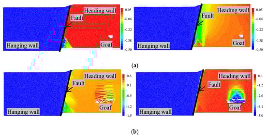
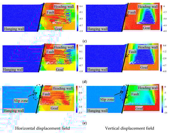
Figure 8.
Displacement field distribution during mining towards the fault direction at the Heading Wall Working Face (unit: m): (a) 195 m from the fault; (b) 135 m from the fault; (c) 90 m from the fault; (d) 45 m from the fault; (e) 0 m from the fault.
3.7. Distribution of Contact Force Chains During Mining Process on Footwall of the Fault
In the fault zone, the stress concentration and unloading areas generated during mining play a critical role in fault slip and instability. Stress concentration primarily occurs under mining disturbances, where local stresses in the fault zone exceed the compressive strength of the rock mass, causing the fault to slip or fracture. Meanwhile, the unloading effect induced by mining reduces the confining pressure on the fault plane, decreasing the frictional resistance of the fault, which further promotes fault slip. The combined influence of stress concentration and unloading areas makes the fault plane more susceptible to slip, thereby increasing the risk of fault instability and potentially triggering dynamic disasters such as fault slip and rockbursts.
Figure 9 reveals the distribution and evolution characteristics of the contact force chain as the lower working face gradually advances towards the fault. Overall, as mining disturbances progress towards the fault, there is a trend of compressive stress gradually decreasing and tensile stress gradually increasing. The ratio of tensile stress to compressive stress rises from 0.06 to 0.13, indicating that as mining advances, the number of force chains in the tensile stress region gradually increases, while the number of force chains in the compressive stress region decreases. At a distance of 195 m from the fault, the force chain ratio of compressive to tensile stress is 0.06, with a relatively uniform distribution of force chains, primarily concentrated within the coal–rock mass. No significant disturbance is observed on either side of the fault. As the working face advances to 125 m, the tensile stress concentration zone extends towards the fault, with the force chain ratio increasing to 0.07. The area near the fault gradually shows a tendency for tensile stress concentration. At 90 m, tensile stress continues to increase, with the force chain ratio further rising to 0.09, indicating that tensile stress inside the fault is expanding and propagating. When the working face reaches 45 m, the ratio of tensile to compressive stress stabilizes at 0.09, and compressive and tensile stresses show significant coupling in the fault-adjacent zone. The force chain distribution becomes more concentrated, with the hanging wall of the fault showing a distinct tensile stress concentration. Finally, when the working face reaches the fault, the ratio of tensile to compressive stress increases to 0.13, forming a significant compressive–tensile coupling effect both inside and outside the fault. Compressive stress is concentrated on the footwall, while the fault damage zone and hanging wall exhibit strong tensile stress concentration. At this stage, the fault enters a stress polarization state before instability, marking a critical phase of potential failure under the coupled effect of mining-induced and tectonic stresses.
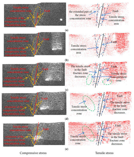
Figure 9.
Distribution of contact force chains during mining towards the fault direction at the footwall working face: (a) 195 m from the fault; (b) 135 m from the fault; (c) 90 m from the fault; (d) 45 m from the fault; (e) 0 m from the fault.
3.8. Distribution of Rock Mass Velocity Field During the Mining Process of Footwall of a Fault
Figure 10 illustrates the spatiotemporal evolution characteristics of the rock mass velocity field as the lower working face gradually advances towards the fault. Overall, the spatial distribution of the velocity field shows a certain correspondence with the displacement field, but velocity is more sensitive in reflecting the development of fault slip and localized damage, especially in the short period before instability, where local acceleration and velocity abrupt changes are more prominent than cumulative displacement. When the working face is 195 m away from the fault, the horizontal and vertical velocities at all monitoring stages are relatively small, with only slight disturbances in the velocity above the goaf. This corresponds to the slow bending phase of the overlying rock, where the rock mass remains in a stable state. As the working face advances to 135–90 m, banded areas of moderate to high velocity gradually appear near the fault zone and above the goaf roof. The velocity isolines become noticeably denser, indicating that the fracture expansion and localized slip processes are accelerating. Although cumulative displacement has not yet reached its peak, velocity anomalies relative to the background field have become apparent. As the working face continues to advance to 45 m and eventually reaches the fault, the horizontal and vertical velocities in the fault damage zone and above the goaf increase sharply within a short time. Local velocity gradients become steep, and frequent changes in motion direction occur, forming large-scale high−velocity concentration zones. The velocity anomalies during this stage are highly synchronized with the development of contact force chain reorganization and stress polarization, which can be regarded as a dynamic precursor to the imminent intense fault slip and tunnel instability. In engineering practice, such velocity anomalies (the appearance of high−velocity concentration zones and abrupt changes in velocity gradients) can serve as criteria for identifying the critical instability state in the fault-adjacent area.
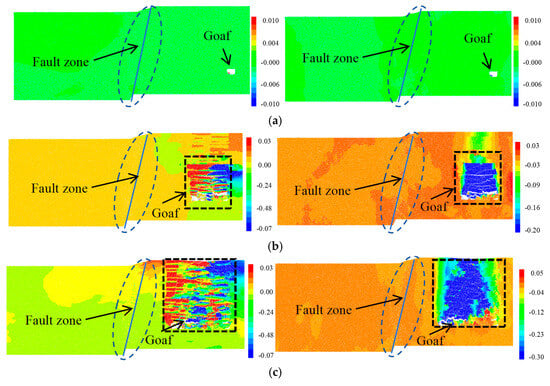
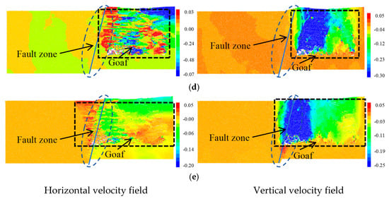
Figure 10.
Distribution of velocity field during mining towards the fault direction at the footwall working face: (a) 195 m from the fault; (b) 135 m from the fault; (c) 90 m from the fault; (d) 45 m from the fault; (e) 0 m from the fault.
4. Discussion
4.1. Evolution of Displacement Field
Figure 11 illustrates the displacement changes along different lines after normal fault mining, with arrows indicating the direction of displacement along each line. The displacement of the rock mass near the fault increases significantly, especially around 10 cm from the fault, where the displacement reaches its maximum. As the distance from the fault increases, the displacement rapidly decreases. This indicates that the rock mass surrounding the fault experiences substantial mining disturbances and undergoes significant deformation, with the deformation concentrated near the fault. As the mining process advances, the displacement gradually decreases, and areas further from the fault are less affected. This concentration and attenuation of displacement reflect stress concentration and instability risks near the fault, providing important theoretical support for mine safety and the prediction and prevention of fault-related disasters.
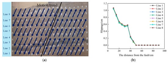
Figure 11.
Variation trend of rock layer displacement with distance from the fault along different measurement lines. (a) Displacement changes after normal fault mining. (b) Displacement difference changes after normal fault mining in the physical model.
4.2. Relationship Between Displacement and Curvature with Distance from the Fault
As shown in Figure 12, with the advancement of mining disturbances, the deformation of the rock mass near the fault gradually intensifies, manifested by significant displacement concentration and sharp changes in curvature. When the distance from the fault is relatively large, the displacement change is small, mainly concentrated above the goaf. However, as mining progresses, vertical displacement reaches its maximum value, showing significant deformation near the fault. At the same time, the curvature value increases from 0.06 to 0.09. This indicates that near the fault, the rock mass undergoes significant deformation and nonlinear response, especially during the formation of “S”-shaped folding. These folds reflect the complex curvature changes in the rock mass due to local stress concentration and tensile stress, particularly near the fault zone under mining disturbances. The increase in curvature directly supports the formation of the “S”-shaped fold, indicating that the deformation of the rock mass is not limited to simple subsidence but is a result of the combined shear and tensile effects, leading to the formation of an “S”-shaped fold.
Figure 12.
Relationship between displacement and curvature with distance from the fault. (a) Vertical displacement changes after normal fault mining. (b) Curvature changes between layers.
4.3. Stress Variation Trends on Both Sides of the Fault
Figure 13 shows the variations in vertical and horizontal stress near the fault. As mining progresses, the stress field in the rock mass near the fault undergoes significant redistribution. Particularly in areas closer to the fault, both vertical and horizontal stress exhibit substantial fluctuations, indicating that the fault is strongly influenced by mining disturbances. Notably, the stress near the fault shows more intense variations, reflecting the stress concentration in localized areas. These significant fluctuations and concentrations in stress could potentially lead to fault slip or rupture, increasing the risk of rock mass instability and suggesting that the stability of this area is compromised. Therefore, the changes in the stress field near the fault provide important reference data for predicting mining disasters and conducting safety assessments.
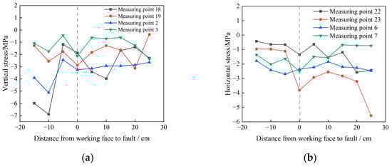
Figure 13.
Stress variation trends on both sides of the fault. (a) Vertical stress variation. (b) Horizontal stress variation.
5. Conclusions
(1) As the dip angle of the fault plane increases, the uniaxial compressive strength of the rock mass significantly decreases. The failure mode evolves from splitting failure to tensile–shear mixed failure, and ultimately to shear failure, indicating that the geometric characteristics of the fault plane dominate the mechanical behavior of the rock mass.
(2) The formation of a normal fault can be divided into five stages: rock layer compressive deformation, fault initiation, propagation, slip, and final stabilization. The deformation of the rock mass in the hanging wall is significantly greater than that in the footwall. Fractures are mainly concentrated during the fault initiation phase, and during the slip-stabilization phase, the fractures gradually close, revealing the profound influence of stress adjustment on fault evolution.
(3) As the working face advances, the layer zone and fracture zone gradually develop, with the floor experiencing initial rupture and the roof subsiding, eventually leading to collapse. In areas near the fault, the rock mass undergoes severe fragmentation, and the collapse rate accelerates, creating a high-risk dynamic disaster zone. Vertical displacement is primarily concentrated above the goaf, while horizontal displacement is locally enhanced on the footwall of the fault, demonstrating significant differences in stress response.
Author Contributions
Conceptualization, Z.X.; Methodology, J.W.; Software, W.D.; Validation, C.M.; Formal analysis, C.M.; Investigation, C.M.; Data curation, J.W.; Writing—original draft, W.D.; Writing—review & editing, Z.X.; Visualization, L.L.; Supervision, L.L.; Project administration, L.L.; Funding acquisition, Z.X. All authors have read and agreed to the published version of the manuscript.
Funding
The research is financially supported by the National Natural Science Foundation of China (No. 52204137), and the Education Department Foundation of Liaoning Province (LJ212510146001).
Institutional Review Board Statement
Not applicable for studies not involving humans or animals.
Data Availability Statement
The original contributions presented in this study are included in the article. Further inquiries can be directed to the corresponding authors.
Conflicts of Interest
On behalf of all authors, the corresponding author states that there is no conflict of interest. The authors declare that they have no known competing financial interests or personal relationships that could have appeared to influence the work reported in this study.
References
- Jiang, Y.; Pan, Y.; Jiang, F.; Dou, L.; Ju, Y. State of the art review on mechanism and prevention of coal bumps in China. J. China Coal Soc. 2014, 39, 205–213. [Google Scholar] [CrossRef]
- Wang, A.; Pan, Y.; Li, Z.; Liu, C.; Han, R.; Lv, X.; Lu, H. Similar experimental study of rockburst induced by mining deep coal seam under fault action. Rock Soil Mech. 2014, 35, 2486–2492. [Google Scholar] [CrossRef]
- Chen, S.; Xia, Z.; Feng, F.; Yin, D. Numerical study on strength and failure characteristics of rock samples with different hole defects. Bull. Eng. Geol. Environ. 2020, 80, 1523–1540. [Google Scholar] [CrossRef]
- Lai, X.; Zheng, J.; Jiang, X.; Chang, B.; Shan, P.; Liu, B. Influential range assessment of dynamic pressure in fault zone with broken rock masses. J. Min. Saf. Eng. 2016, 33, 361–366. [Google Scholar] [CrossRef]
- Cao, M.-H.; Yang, S.-Q.; Du, S.-G.; Li, Y.; Wang, S.-S. Study on fault-slip process and seismic mechanism under dynamic loading of hard roof fracture disturbance. Eng. Fail. Anal. 2024, 163, 1008598. [Google Scholar] [CrossRef]
- Tang, C.; Wang, J.; Zhang, J. Preliminary engineering application of microseismic monitoring technique to rockburst prediction in tunneling of Jinping II project. J. Rock Mech. Geotech. Eng. 2010, 2, 193–208. [Google Scholar] [CrossRef]
- Zheng, M.; Liang, Y.; Staat, M.; Li, Q.; Li, J. Discontinuous fracture behaviors and constitutive model of sandstone specimens containing non-parallel prefabricated fissures under uniaxial compression. Theor. Appl. Fract. Mech. 2024, 131, 104373. [Google Scholar] [CrossRef]
- Wei, M.; Qiao, L.; Li, L.; Li, Q.; Chen, L. Crack coalescence and failure behaviors in slate specimens containing a circular cavity and a pre-existing flaw pair under uniaxial compression. Theor. Appl. Fract. Mech. 2024, 134, 104721. [Google Scholar] [CrossRef]
- Kou, H.; Shi, Z.; Xia, C.; Zhou, Y.; Meng, S. Dynamic simulation and failure analysis of intermittently jointed rock cells and slopes based on a novel spring-based smoothed particle hydrodynamics method. Bull. Eng. Geol. Environ. 2024, 83, 135. [Google Scholar] [CrossRef]
- Li, Z.; Dou, L.; Cai, W.; He, J.; Wang, G.; Liu, J.; Han, R. Fault-Pillar Induced rock burst mechanism of thick coal seam in deep mining. Chin. J. Rock Mech. Eng. 2013, 32, 333–342. [Google Scholar]
- Sun, C.; Yang, Z.; Yang, H. Seismites characteristics and significance of exploration and development from coal measure gas of Shanxi Formation in Xishan Coalfield. Coal Sci. Technol. 2021, 49, 136–144. [Google Scholar] [CrossRef]
- Rice, R.J. Heating and weakening of faults during earthquake slip. J. Geophys. Res. Solid Earth 2006, 111. [Google Scholar] [CrossRef]
- Xia, Z.-G.; Liu, S.; Bian, Z.; Song, J.; Feng, F.; Jiang, N. Mechanical Properties and Damage Characteristics of Coal-Rock Combination with Different Dip Angles. KSCE J. Civ. Eng. 2021, 25, 1687–1699. [Google Scholar] [CrossRef]
- Shi, H.; Liu, J.; Liu, S.; Chang, J.; Li, F. Evolutionary patterns of shear behavior and crack distribution during fault slip. Int. J. Rock Mech. Min. Sci. 2024, 177, 105747. [Google Scholar] [CrossRef]
- Zhang, J.; Guo, L.; Tu, K.; Mu, W. Experimental and numerical investigations of concealed fault zones’ activation characteristics with multiple confined aquifers underlying coal floor: A case study from Shanxi, northern China. Environ. Earth Sci. 2025, 84, 98. [Google Scholar] [CrossRef]
- Li, Y.; Yang, J.; Gao, X. Fault slip amplification mechanisms in deep mining due to heterogeneous geological layers. Eng. Fail. Anal. 2025, 169, 109155. [Google Scholar] [CrossRef]
- Li, Y.; Yuan, L.; Zhang, Q. Brittle rock mass failure in deep tunnels: The role of infilled structural plane with varying dip angles. Int. J. Rock Mech. Min. Sci. 2024, 176, 105721. [Google Scholar] [CrossRef]
- Shan, R.; Dou, H.; Liu, N.; Bai, H.; Meng, H.; Sun, P.; Xu, Z.; Bai, Y.; Zhao, Y. Experimental and numerical analysis of Brazilian splitting mechanical properties and failure mechanism for composite discs. Constr. Build. Mater. 2024, 442, 137620. [Google Scholar] [CrossRef]
- Wang, K.; Zhao, E.; Guo, Y.; Du, F.; Ding, K. Effect of loading rate on the mechanical and seepage characteristics of gas-bearing coal–rock and its mechanical constitutive model. Phys. Fluids 2024, 36, 26606. [Google Scholar] [CrossRef]
- Wang, P.; Yang, T.; Wang, S.; Liu, H.; Zhang, Z. Study on the slip characteristics of rock inhomogeneous friction interface. Geomech. Geophys. Geo-Energy Geo-Resour. 2023, 9, 40. [Google Scholar] [CrossRef]
- Guo, D.; Zuo, J.; Zhang, Y.; Yang, R. Research on strength and failure mechanism of deep coal-rock combination bodies of different inclined angles. Rock Soil Mech. 2011, 32, 1333–1339. [Google Scholar] [CrossRef]
- Meng, F.; Yue, Z.; Li, M.; Han, J.; Cai, Q.; Wang, W.; Hu, D.; Zhang, C. Frictional Sliding Behaviour of Rough Fracture in Granite Under True Triaxial Loading with Implications for Fault Reactivation. Rock Mech. Rock Eng. 2024, 57, 197–217. [Google Scholar] [CrossRef]
- Zhang, C.; Zhang, L.; Tao, Z.; Fang, Z.; Xie, Q.; Cui, G. Study on Rock Type Effect of Fault Sliding Stability. Rock Mech. Rock Eng. 2024, 57, 1915–1938. [Google Scholar] [CrossRef]
- Fang, Q.; Zhou, K.; Liu, X. Particle flow analysis of failure mechanism of intermittent jointed rock mass under different confining pressure. J. Cent. South Univ. 2014, 45, 3536–3543. [Google Scholar]
- Eyre, T.S.; Eaton, D.W.; Garagash, D.I.; Zecevic, M.; Venieri, M.; Weir, R.; Lawton, D.C. The role of aseismic slip in hydraulic fracturing–induced seismicity. Sci. Adv. 2019, 5, eaav7172. [Google Scholar] [CrossRef] [PubMed]
- Han, K.; Yu, Q.; Zhang, H.; Li, M. Mechanism of fault activation when mining on hanging- wall and foot- wall. J. China Coal Soc. 2020, 45, 1327–1335. [Google Scholar] [CrossRef]
- Xia, Z.; Wang, J.; Dong, W.; Ma, C.; Chen, B. The Formation Process of Coal-Bearing Strata Normal Faults Based on Physical Simulation Experiments: A New Experimental Approach. Processes 2025, 13, 2799. [Google Scholar] [CrossRef]
- Ma, L.; Zhao, B.; Xu, H.; Cao, H. Research on water inrush mechanism of fault coupling bed separation with fullymechanized sublevel caving of ultra-thick coal seam. J. China Coal Soc. 2019, 44, 567–575. [Google Scholar] [CrossRef]
- Guo, Y.; Wang, K.; Du, F.; Guo, H.; Li, K.; Wang, Y. Mechanical-permeability characteristics of composite coal rock under different gas pressures and damage prediction model. Phys. Fluids 2024, 36, 36615. [Google Scholar] [CrossRef]
- Cai, W.; Dou, L.; Si, G.; Hu, Y. Fault-Induced Coal Burst Mechanism under Mining-Induced Static and Dynamic Stresses. Engineering 2021, 7, 687–700. [Google Scholar] [CrossRef]
- Wang, H.; Li, T.; Wang, Q.; Hao, X.; Xue, P. Study On Upward Mechanism of Influence Range of Fault Stress Induced by Mining Disturbance. Eng. Mech. 2024. [Google Scholar] [CrossRef]
- Li, Y.; Gao, X.; Yang, J.; Bai, E. Quantitative 3-D investigation of faulting in deep mining using Mohr–Coulomb criterion and slip weakening law. Geomech. Geophys. Geo-Energ. Geo-Resour. 2025, 11, 10. [Google Scholar] [CrossRef]
- Wang, J.; Wei, W.; Zhang, J.; Mishra, B.; Li, A. Numerical investigation on the caving mechanism with different standard deviations of top coal block size in LTCC. Int. J. Min. Sci. Technol. 2020, 30, 583–591. [Google Scholar] [CrossRef]
- Wang, H.; Xue, S.; Shi, R.; Jiang, Y.; Gong, W.; Mao, L. Investigation of Fault Displacement Evolution During Extraction in Longwall Panel in an Underground Coal Mine. Rock Mech. Rock Eng. 2020, 53, 1809–1826. [Google Scholar] [CrossRef]
- Babets, D.; Sdvyzhkova, O.; Hapieiev, S.; Shashenko, O.; Vasyl, V. Multifactorial analysis of a gateroad stability at goaf interface during longwall coal mining–A case study. Min. Miner. Depos. 2023, 17, 9–19. [Google Scholar] [CrossRef]
- Li, Y.; Fukuyama, E.; Yoshimitsu, N. Mining-induced fault failure and coseismic slip based on numerical investigation. Bull. Eng. Geol. Env. 2024, 83, 386. [Google Scholar] [CrossRef]


Disclaimer/Publisher’s Note: The statements, opinions and data contained in all publications are solely those of the individual author(s) and contributor(s) and not of MDPI and/or the editor(s). MDPI and/or the editor(s) disclaim responsibility for any injury to people or property resulting from any ideas, methods, instructions or products referred to in the content. |
© 2025 by the authors. Licensee MDPI, Basel, Switzerland. This article is an open access article distributed under the terms and conditions of the Creative Commons Attribution (CC BY) license (https://creativecommons.org/licenses/by/4.0/).