Abstract
This study designed a novel coherent tuyere device capable of adjusting the core length of the jet flow. Physical experiments were first conducted to investigate how the number of secondary nozzles in the coherent tuyere affects the gas–solid two-phase flow behavior within the raceway during the blasting process. Subsequently, the Computational Fluid Dynamics (CFD) method was employed to examine the influence of structural parameters on jet morphology in coherent tuyere. Finally, computational fluid dynamics and discrete phase method (CFD-DPM) was adopted, and the velocity, temperature, and composition distribution patterns within the raceway were analyzed following the injection of hydrogen-rich gas through the coherent tuyere. The results of the physics experiment indicate that increasing the number of secondary nozzles in the coherent tuyere can significantly enlarge the raceway size and broaden the particle kinematic zone, thereby enhancing particle fluidization at the periphery of the raceway. CFD numerical simulation results indicate that increasing the number of secondary nozzles of the tuyere can effectively extend the length of the velocity jet core region. Compared with conventional tuyeres, a six-nozzle coherent tuyere can increase the core length of the blast velocity by about 40%. When the diameter of the secondary nozzles in the coherent tuyere is doubled, the core length of the blast velocity increases by 10%. The results of the CFD-DPM coupled simulation show that unburned carbon particles flow and combust along the periphery of the raceway with the hot air, leading to the formation of a high-temperature region in this area. After the injection of hydrogen-rich gas through the coherent tuyere, the temperature in the raceway decreased significantly. A high-concentration region of H2 appeared at the periphery of the raceway, while the high-concentration CO region increased in concentration and gradually extended toward the upper part of the raceway. This research achievement is of significant importance for optimizing blast furnace blast kinetic energy and hydrogen-rich gas injection.
1. Introduction
With the worsening of environmental pollution and growing global demands for energy conservation and emission reduction, energy efficiency optimization and low-carbon smelting in the steel industry have attracted increasing attention. In recent years, the global annual average crude steel production has reached 1.8826 billion tons, resulting in CO2 emissions that account for 4% to 7% of global total emissions. Of these emissions, those from blast furnace ironmaking constitute approximately 90% of the steel industry’s total carbon emissions [1,2,3]. Therefore, it is essential to optimize the operation of blast furnace for attaining a more energy-efficient and low-carbon production process [4,5,6]. During the operation of a blast furnace, hot air is blown in through the tuyeres, forming a raceway. This raceway serves as both the primary heat source of the blast furnace and the origin of the reducing gases within the furnace interior. Obviously, the structure of the tuyere and the composition of gas it blasts significantly influence the conditions within the raceway.
Given that blast furnace tuyere equipment operates in the harsh conditions of the blast furnace raceway, optimizing its structural design requires in-depth research into multiphase flow and combustion behavior within this region. Physical experimental studies have primarily focused on the development of raceway prediction models [7,8,9], which effectively reveal the influence of inlet air and particulate material parameters on the evolution patterns of raceway. However, it is highly challenging to quantitatively characterize the velocity, temperature, and gas flow fields of coke particles during the formation of the raceway, particularly the gas–solid two-phase dynamic behavior and micro-mechanical mechanisms within the particle bed, through physical experiments. In this case, a simulation approach based on the coupling of Computational Fluid Dynamics (CFD) and the Discrete Element Method (DEM) can be employed to address the limitations of physical experiments. Zhang et al. applied this method to investigate the heat transfer characteristics and microstructural evolution of particles with different shapes in the raceway of a blast furnace [10,11,12]. Li et al. conducted simulation studies on transport phenomena and thermochemical behavior within the raceway of blast furnaces. They systematically analyzed the effects of process parameters on coke combustion characteristics, thermochemical behavior, and microstructure of the coke bed in the raceway and established a predictive model for raceway dimensions [13,14,15,16]. These research findings provide valuable guidance for the upgrading and modification of blast furnace tuyere structures. Building on this foundation, subsequent studies have fixed the dimensions of the raceway and investigated hydrogen-rich gas injection through blast furnace tuyeres. They investigated the influence of hydrogen injection position, lance structure, and blast parameters on the velocity, temperature, and species distributions of gases inside the furnace and established the quantitative relationship between hydrogen-rich gas and smelting performance indicators. For example, Bae et al. studied the multiphase flow and chemical reaction behavior in the raceway during co-injection of hydrogen-rich gas and pulverized coal [17]. Zhang et al. analyzed the effects of co-injecting hydrogen, natural gas, coke oven gas, and recycled top gas with pulverized coal on the raceway [18]. Meanwhile, several studies have established the optimal relationship between hydrogen-rich gas and pulverized coal injection rates through numerical simulations [19,20,21,22]. However, these studies consistently indicate that hydrogen-rich gas injected through the tuyere not only reduces the blast kinetic energy but also significantly degrades coal combustion efficiency. To further optimize process control and operational parameters for blast furnaces’ blasting process, this study developed a novel coherent tuyere device to optimize the kinetic energy of blasting and the injection of hydrogen-rich gas. Our preliminary research has systematically investigated the flow and combustion behavior of hydrogen-rich gas injected through novel coherent tuyere, examining the effects of hydrogen-rich gas injection volume and velocity on blast kinetic energy and pulverized coal combustion behavior [23,24]. Unlike previous studies, this research focuses on investigating the effects of the structural parameters of a novel coherent tuyere on the blasting process. The study simultaneously compared changes in heat and mass within the raceway generated by conventional blast and hydrogen-rich gas injection. This research aims to develop a novel tuyere device for optimizing blast furnace tuyere kinetic energy and hydrogen-rich blast furnace injection technology.
Firstly, this study conducted cold-state physical experiments on gas–solid two-phase flow during the blasting process of a novel coherent tuyere. The investigation focused on the influence of the number of secondary nozzles in the tuyere on the morphology of the raceway, particle motion patterns, and pressure and velocity distributions during the blasting process. Secondly, through CFD numerical simulation, the jet characteristics of the coherent tuyere blowing process were systematically analyzed. Through numerical simulations, the influence of the number of secondary nozzles, secondary nozzle diameter, and spacing between primary and secondary nozzles on gas flow behavior during the blowing process was systematically investigated. Finally, a CFD-DPM coupled simulation was employed to investigate the flow field, temperature field, and species distribution patterns within the raceway during hydrogen-rich gas injection through the novel coherent tuyere, as well as the resulting changes compared to the conventional blasting process.
2. Methodology
2.1. Experimental Equipment and Method
A 1:10 scale experimental tuyere platform was established based on a 3200 m3 blast furnace from a specific steel plant, as illustrated in Figure 1. Since this chapter primarily focuses on the evolution characteristics of the raceway during the coherent tuyere blowing process, a quasi-two-dimensional cold-flow physical model was developed to investigate the local raceway under laboratory conditions. The model consists mainly of an air supply system, an air storage tank, and data acquisition instruments. Furthermore, the coherent tuyere was fabricated using 3D printing technology. The workflow of the entire experimental system is as follows: The air compressor generates gas at a pressure of 0.4 MPa, which is then delivered to the air storage tank. The density of the particle material used in the experiment is 910 kg/m3, and the particle morphology is spherical. In the experiment investigating the effect of the number of coherent tuyere on raceway characteristics, particles with a diameter of 0.2 mm were selected. The research on the pressure variation law in the raceway during the blasting process of traditional tuyeres and coherent tuyere selected three particle size ratios, namely, 50% of 1.5 mm and 50% of 2.0 mm, 50% of 0.5 mm and 50% of 2.0 mm, and 50% of 0.2 mm and 50% of 2.0 mm. Subsequently, the gas is transported through the delivery pipeline to the tuyere, with flow rate regulated by a flow meter and control valve. During the experiment, gas–solid physical and kinetic parameters were determined according to the principle of similarity, with the calculation formulas provided in Table 1. The full nomenclature is provided in Glossary section.
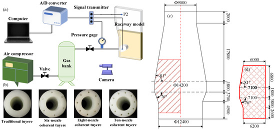
Figure 1.
Schematic diagram of experimental process: (a) experiment apparatus, (b) tuyere structure, (c) actual size of blast furnace (mm), (d) local region size of blast furnace (mm).

Table 1.
The principle of dynamic similarity is expressed by the equation.
2.2. Numerical Method and Simulation Conditions
2.2.1. Governing Equations
In this study, the continuity, momentum, and energy equations are employed to characterize the fluid flow. The standard k-ε turbulence model is adopted to calculate turbulent kinetic energy and dissipation rate. The motion trajectory of discrete phase particles is calculated by the balance of the forces on the particles. The equation for calculating the forces on particles in the Lagrange reference frame. The kinetics of devolatilization reaction of pulverized coal adopts the model proposed by Kobayashi [25], which weighs the two kinetic rates. The carbon combustion reaction in pulverized coal and coke are simulated by Kinetics/Diffusion-limiting rate model [26]. The governing equations are shown in Table 2. The full nomenclature is provided in Glossary section.
Table 2.
Governing equations and turbulence model.
2.2.2. Simulation Conditions
In the simulations, the multiphase flow and combustion process was simulated with ANSYS-FLUENT 19.0, a three-dimensional (3D) geometric model of the coherent tuyere is established for a blast furnace (3200 m3), as shown in Figure 2a. Here, the depth of the raceway is around 2 m determined by the empirical formula. In this case, the geometry and meshes of coal lance, coherent tuyere, coke inlet, and reaction region are shown in Figure 2b. And the operating parameters used in the simulations are shown in Table 3. The coal lance is positioned in the center of the tuyere, and the pulverized coal components are listed in Table 4. The composition of hydrogen-rich gas is listed in Table 5. The overall chemical reactions used in this study are shown in Table 6 The accessory foramina surrounding the front of the tuyere are used to inject hydrogen-rich gas, and the outlet pressure is 0.3 MPa. The whole calculation area is divided by polyhedral mesh. Throughout the entire calculation process, the gas phase remains in a steady state while the particle phase is in a non-steady state, with a time step of 1.25 × 10⁻⁴. The computational process is discretized in space using a cell-based least-squares approach, and the SIMPLE method is employed for solving the coupled pressure-velocity problem. To ensure the accuracy of the simulation results, the second-order wind scheme is used. When the residual value of the energy and radiation is smaller than 10−6, the value of other variables is smaller than 10−3, the solution is considered to converge.
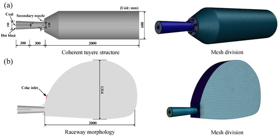
Figure 2.
Coherent tuyere and Raceway structure: (a) morphology, (b) mesh division.
Table 3.
Operating parameters used in the simulations.
Table 4.
Proximate and ultimate analyses of pulverized coal.
Table 5.
The average gas composition of the hydrogen-rich fuel.
Table 6.
Key reactions and parameters in the model.
3. Results and Discussion
3.1. Model Validation
In the previous work [23,24], the validity and accuracy of the mesh sensitivity, flow and combustion models employed in this study have been demonstrated. To achieve mesh-independent verification and minimize numerical errors related to the mesh, three different grid levels were utilized in the present study: coarse (200,000 cells), medium (400,000 cells) and fine (600,000 cells). Figure 3a shows the centerline velocity of the tuyere along the blast direction for each grid configuration. The coarse grid calculations exhibited a more pronounced drop in centerline velocity, while the medium grid provided more accurate predictions. To further validate the accuracy of the simulation results in this study, Figure 3b presents a comparison between numerical simulations and physical experiments. As shown in the figure, the maximum deviation between the experimental and numerical results does not exceed 4.5%. The numerical simulation of the coherent tuyere blasting process demonstrates reasonable accuracy. Furthermore, the variation trends of CO and O2 concentrations along the tuyere centerline, as predicted by the computational results, are consistent with those reported in previous studies [22], as illustrated in Figure 3c. As shown in the figure, the simulated O2 concentration distribution generally agrees with the experimental data, whereas the CO concentration distribution is slightly higher than the measured values. The main reason for the error lies in the fact that in the industrial test, a portion of CO was used to reduce the liquid iron oxide in the raceway, while the existence of liquid iron oxide was ignored in this study.
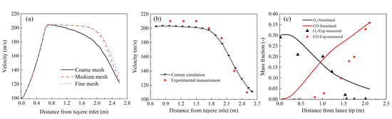
Figure 3.
Comparison between experimentally measured data and current simulation results: (a) for different grid configurations, (b) comparison of velocity along the centerline of the tuyere, (c) comparison of component along the centerline of the tuyere.
3.2. Analysis of Experiment Results of Coherent Tuyere Blasting Process
At the blast furnace tuyere, coke particles are gradually entrained by high-speed hot air and transported into the voids of the coke bed. Once the coke bed reaches a certain level of densification, the gas flow deflects outward, inducing the peripheral coke particles to undergo a counterclockwise circulating raceway. Figure 4 presents the morphological characteristics of the raceway after stabilization during the blast process of the coherent tuyere with secondary nozzles numbered 0, 6, 8, and 10. As the number of secondary nozzles in the coherent tuyere increases, the volume of the raceway cavity expands, indicating that the coherent blast configuration mitigates the decay of blast kinetic energy. Simultaneously, when employing a coherent tuyere for forced air supply, the degree of particle fluidization at the periphery of the raceway increases. Moreover, as the number of secondary nozzles in the coherent tuyere increases, the blast supply area expands, thereby further promoting the movement of peripheral particles and enhancing the fluidization intensity within the raceway cavity.
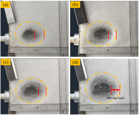
Figure 4.
Raceway morphologies in the stable stage: (a) conventional tuyere, (b) six-nozzle coherent tuyere, (c) eight-nozzle coherent tuyere, (d) ten-nozzle coherent tuyere.
To quantitatively characterize the morphology of the raceway during the blast process of both conventional and coherent tuyere, Figure 5 presents the dimensions and the width of the particle motion band in the stabilized raceway. As shown in Figure 5a, the depth of the raceway exceeds its height under both airflow configurations. As the number of secondary nozzles in the coherent nozzle increases, the overall dimensions of the raceway gradually expand. Concurrently, the height of the raceway increases slightly more than its depth with increasing number of secondary nozzles. This indicates that during the blasting, the excess kinetic energy is insufficient to propel the dense particle bed at the flow front, and instead tends to disrupt the relatively loose particle structure in the upper part of the raceway. As shown in Figure 5b, with the increase in the number of secondary holes of the cluster air nozzle, the width of the fluidized particle movement zone gradually decreases at the edge of the recirculation zone, and the rate of decrease gradually slows down.
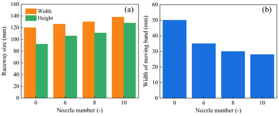
Figure 5.
Analysis of raceway characteristics in stable stage: (a) the raceway size (b) width of particle moving band.
Figure 6 illustrates the variation gas flow velocity at a fixed hearth level during the blasting, comparing the performance of traditional tuyeres and coherent tuyeres under different blast air flow rates. A comparison of Figure 6a,b reveals that, within the raceway, the coherent tuyere consistently achieves slightly higher gas velocities than the conventional tuyere across all flow rates. The diagram also shows that gas velocity decreases toward the center of the furnace hearth, with the slope of the curve gradually flattening and eventually approaching a horizontal line, indicating that the coherent tuyere system exerts minimal influence on gas flow in the central region of the hearth. At the same time, as the blast air flow rate increases, the gas velocity at a fixed position within the furnace hearth also increases correspondingly.
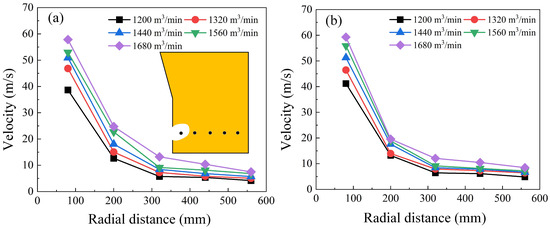
Figure 6.
The evolution of tuyere center line velocity, where: (a) traditional tuyere blast, (b) coherent tuyere blast.
Figure 7 illustrates the internal pressure distribution patterns within packed beds of varying particle sizes during the blasting process for both conventional and coherent tuyere. As shown in Figure 7a, with an increasing particle size ratio, finer particles progressively fill the interstitial voids, leading to a more densely packed bed structure. When the initial blast is introduced, the gas exerts a force that drives fine particles to further occupy the interstitial voids, leading to a denser periphery in the raceway. Consequently, as the particle size ratio within the packed bed increases, the high-pressure region within the raceway gradually expands. When using a coherent tuyere for blasting, as shown in Figure 7b, the pressure within the raceway increases. Moreover, in comparison with conventional tuyere, the high-pressure region within the particle bed shifts toward the center during blasting. This indicates that the coherent tuyere more effectively propels particles in the direction of the blasting, thereby facilitating the filling of pores at the periphery of the raceway. As a result, a denser particle arrangement is achieved, leading to a central shift in the high-pressure zone.
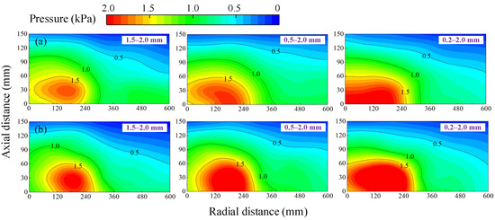
Figure 7.
Pressure distribution in the hearth: (a) traditional tuyere blast, (b) six-nozzle coherent tuyere blast.
3.3. Analysis of Simulation Results of Coherent Tuyere Jet Characteristics
The aforementioned experiments have demonstrated that the coherent blasting configuration exerts a significant influence on the morphology of the raceway and the motion state of particles. Physical experiments describe the evolution of gas–solid dynamics at the macroscopic level, while numerical simulations can further elucidate gas flow behavior and momentum transfer mechanisms at the microscopic level. Figure 8a presents the velocity distribution in the axial cross-section during the blasting process for both the conventional and coherent tuyere. It can be observed that after the hot air is ejected from the tuyere, it transfers momentum to the surrounding stationary gas, resulting in an outward expansion of the jet velocity. As the hot air propagates forward, this lateral expansion intensifies, while the central high-velocity core gradually diminishes. In contrast, during the operation of the coherent tuyere blasting, the hot air ejected from the tuyere is shielded by surrounding assisting gases, which suppresses its outward expansion and leads to an intensification of the central high-velocity region. Figure 8b illustrates the variation in velocity along the centerline of the tuyere under different numbers of secondary nozzles in the coherent tuyere blasting process. As shown in the figure, hot air accelerates upon ejection from the tuyere small sleeve. After exiting the tuyere, the peak central velocity is maintained over a certain distance before gradually decreasing. Compared with conventional tuyeres, a six-nozzle coherent tuyere can increase the core length of the blast velocity by about 40%. As the number of secondary nozzles increases, the effect on the central velocity of the blasting progressively diminishes. When the number of secondary nozzles in the inlet exceeds 6, the variation in the centerline velocity profile of the hot air becomes negligible. Figure 8c shows that doubling the diameter of the secondary nozzles increases the core length of the blasting velocity by 10%. Figure 8d indicates that, compared to the number and diameter of the secondary nozzles, the spacing between the secondary nozzles and the central bore has negligible influence on the blasting velocity.
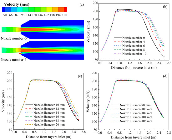
Figure 8.
Schematic diagram of blasting process at coherent tuyere and evolution of velocity along the centerline of the tuyere: (a) velocity distributions, (b) different number of secondary nozzles, (c) different diameter of secondary nozzles, (d) different distance between main and secondary nozzles.
Figure 9 shows the spatial velocity distribution of the two air streams from the tuyere and its secondary nozzles before merging during the blasting process. As shown in the figure, the central high-velocity region continuously narrows along the direction of the hot air flow. The airflow from the secondary nozzles gradually converges toward the center of blasting while undergoing velocity decay, eventually merging with the central hot air stream to form a unified flow. Furthermore, the airflow from the secondary nozzles at the tuyere exhibits significant attenuation, with its velocity approaching that at the edge of the hot air stream at a distance of 0.04 m from the tuyere.
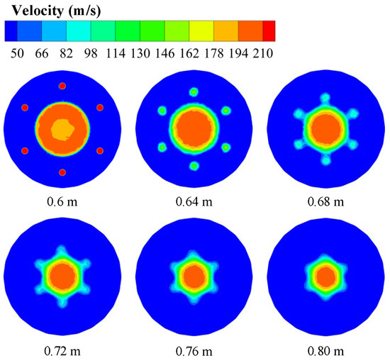
Figure 9.
Velocity distributions of different radial sections in the blast process of coherent tuyere.
Figure 10 illustrates the convergence characteristics of hot air and airflow of secondary nozzles during the blasting process of the coherent tuyere. Analysis of velocity variations along the centerline across different radial cross-sections before the merging of primary and secondary airflows reveals that the number of auxiliary ports in the coherent tuyere has no significant influence on the central blasting zone. The number of secondary nozzles in the coherent tuyere exerts a certain influence on the velocity distribution in the vicinity of the convergence point of the two airflows. At the outlet of the tuyere, relatively high velocities are observed at the center of the secondary nozzles. These velocities gradually decrease in the direction of airflow. Near the convergence point, as the number of secondary nozzles in the coherent tuyere increases, the velocity at the same location decreases. This indicates that increasing the number of secondary nozzles induces mutual interference between adjacent airflows, leading to energy dissipation.
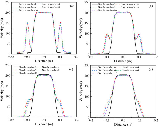
Figure 10.
Velocity evolution of different radial sections in the blast process of coherent tuyere, where: (a) 0.64 m, (b) 0.68 m, (c) 0.72 m, (d) 0.76 m.
3.4. Analysis of the Effect of Hydrogen-Rich Gas Injection on the Raceway
This section presents a simulation study on the flow and combustion characteristics inside the raceway under the operation of a novel coherent tuyere for hydrogen-rich gas injection. Figure 11a compares the velocity distributions during blast processes for a traditional tuyere and a coherent tuyere with hydrogen-rich gas injection. It can be observed that the airflow within the raceway exhibits a counterclockwise rotation, forming a stagnant region at its center. When the swirling flow reaches the region above the tuyere, it impinges on the airflow ejected from the tuyere, causing the blast to deflect downward. This observation is consistent with the findings of Zhang et al. [18]. Figure 11b compares the temperature distribution within the raceway during traditional blasting and coherent injection of hydrogen-rich gas. As shown in the figure, during the conventional blast process, coke and pulverized coal falling in front of the tuyere are transported by the hot air stream, continuing to flow and combust, ultimately forming a high-temperature zone at the raceway periphery. Following the coherent injection of hydrogen-rich gas in a jet stream, both the overall and local temperatures within the raceway decrease, while the local temperature distribution becomes similar to that of a conventional blasting process.
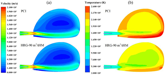
Figure 11.
Velocity and temperature distribution in the raceway: (a) velocity, (b) temperature.
This section also investigates the distribution patterns of H2 and CO components within the raceway during both the conventional blasting process and the hydrogen-rich gas coherent injection process, as shown in Figure 12. It can be seen from Figure 12a that the higher concentration of H2 is mainly concentrated at the raceway periphery during the conventional blasting process. With the injection of hydrogen-rich gas, a high-concentration H2 zone appears at the nozzle outlet, and the H2 concentration increases at the raceway periphery. Since H2 reacts with O2 upon entering the raceway, its presence is scarcely detectable in the central region of the raceway. As the hot air moves forward, the unreacted carbon react with H2O to produce H2, resulting in a detectable amount of H2 at the periphery of the raceway. As shown in Figure 12b, CO begins to form at the tuyere, and its concentration gradually increases in the direction of hot air flow. Furthermore, the concentration at the periphery of the flow is higher than at the center of the blast stream. After injecting hydrogen-rich gas in a coherent manner, the high-concentration CO zone at the periphery of the flow stream expands, while the high-concentration zone gradually extends upward into the raceway.
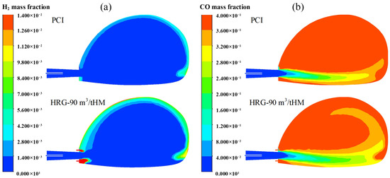
Figure 12.
Mass distributions in the raceway: (a) H2, (b) CO.
4. Conclusions
This paper presents a systematic investigation of the airflow process in coherent tuyere blasting. Through physical experiments and numerical simulations, the study examines the effects of the number of secondary nozzles, their diameter, and the spacing between the secondary nozzles and the central hole on gas–solid flow behavior during the blasting process. Simultaneously, a mathematical–physical model of the blast furnace raceway was established based on the multiphase flow and combustion processes involving coke, hydrogen-rich gas, and pulverized coal. This model systematically analyzes the multiphase flow and combustion characteristics within the raceway following the injection of hydrogen-rich gas into the blast furnace. The main conclusions are as follows:
- (1)
- Physical experiments demonstrate that increasing the number of secondary nozzles in the coherent tuyere can expand the cavity volume of the raceway and promote particle fluidization at its edge. The coherent tuyere blasting method is adopted, which can delay the attenuation of blast kinetic energy and improve blast efficiency. Compared to conventional tuyere, the coherent tuyere system shifts the high-pressure zones toward the center of the particle bed. This configuration facilitates more effective particle transport in the airflow direction, resulting in a fluidization particle system.
- (2)
- CFD simulation studies show that the number of secondary nozzles in a coherent tuyere has a limited effect on the core region of the jet flow. Compared with conventional tuyeres, a six-nozzle coherent tuyere can increase the core length of the blast velocity by about 40%. When the number of secondary nozzles exceeds six, the variation in the hot air centerline velocity profile becomes negligible. When the diameter of the secondary nozzles in the coherent tuyere is doubled, the core length of the jet velocity increases by 10%. In addition, the airflow from the secondary nozzles of the coherent tuyere undergoes severe decay, with its velocity approaching that of the hot air edge within 0.04 m from the tuyere outlet.
- (3)
- CFD-DPM coupled simulation studies show that unburned carbon powder flow and burn along the edge of the raceway with the hot air, creating a high-temperature zone at the raceway’s periphery. Following the injection of hydrogen-rich gas, the temperature within the raceway decreased significantly. A high-concentration region of H2 formed at its periphery, while the high-concentration CO region expanded and gradually migrated upward.
Author Contributions
Conceptualization, P.H. and J.Z.; methodology, Y.F. and P.X.; validation, Y.W.; writing—original draft preparation, P.H. and Y.X.; writing—review and editing, Y.F. and P.X.; funding acquisition, J.Z. All authors have read and agreed to the published version of the manuscript.
Funding
The authors are grateful to the National Natural Science Foundation of China (52074150) for the financial support of current work.
Data Availability Statement
The original contributions presented in this study are included in the article. Further inquiries can be directed to the corresponding authors.
Conflicts of Interest
Author Yingshi Xu were employed by the Angang Steel Corporation Limited. The remaining authors declare that the research was conducted in the absence of any commercial or financial relationships that could be construed as potential conflicts of interest.
Glossary
| Nomenclature | |
| Ap | Surface area of particle, m2 |
| CD | Drag force coefficient, - |
| cg | Specific heat capacity of gas, J/(kg·K) |
| cp | Specific heat capacity of particle, J/(kg·K) |
| D0 | diffusion rate coefficient, - |
| d | Tuyere diameter, mm |
| dp | particle diameter, mm |
| particle-fluid drag force on particle i, N | |
| fh | Heat absorption fraction, % |
| Gb | Turbulence kinetic energy due to buoyancy, m2/s2 |
| Gk | Turbulence kinetic energy generated by the mean velocity gradient, m2/s2 |
| g | gravitational acceleration, m/s2 |
| Hreac | Heat released by the surface reaction, J/m2 |
| h | heat transfer coefficient, W(m2·K) |
| kg | gas thermal conductivity, W/(m·K) |
| mp | mass of particle i, kg |
| mv | volatile mass, kg |
| n | Tuyere number, - |
| P | gas pressure, Pa |
| P0 | standard atmospheric pressure, Pa |
| Pox | the partial pressure of oxidant species in the gas surrounding the combusting particle, Pa |
| Qg,wall | convective heat transfer rate between gas and wall, W |
| Qg,i | convective heat transfer rate between particle i and gas, W |
| Qrad | radiative heat transfer rate between particle i and surrounding environment, W |
| Tg | temperature of gas, K |
| T0 | Gas temperature under standard conditions, K |
| Local temperature of the continuous phase, K | |
| gas velocity, m/s | |
| relative particle velocity, m/s | |
| Greek letters | |
| αg | voidage, - |
| μg | gas molecular viscosity, kg/(m·s) |
| υ | Gas kinematic viscosity, m2/s |
| ρ0 | Gas density under standard conditions, kg/m3 |
| ρp | density of particles, kg/m3 |
| ρg | gas density, kg/m3 |
| σ | STEFAN-Boltzmann constant, W/(m2·K4) |
| gas phase stress tensor, Pa |
References
- Li, M.; Li, Z.; Li, C.; Wu, G.Y.; An, X.Z.; Zhao, H.; Fu, H.T.; Yang, X.H.; Zou, Q.C. Numerical insights on the combustion characteristics in the low-carbon blast furnace raceway with hydrogen-rich gas injections. Int. J. Hydrogen Energy 2025, 100, 341–354. [Google Scholar] [CrossRef]
- Zhang, J.L.; Fu, H.Y.; Liu, Y.X.; Dang, H.; Ye, L.; Conejo, A.N.; Xu, R.S. Review on biomass metallurgy: Pretreatment technology, metallurgical mechanism and process design. Int. J. Miner. Metall. Mater. 2022, 29, 1133–1149. [Google Scholar]
- Li, Q.; Wang, J.S.; She, X.F.; Xu, Q.G.; Wang, G.; Zuo, H.B. Feasibility and comprehensive evaluation of the application of different low-carbon technologies in the iron and steel industry. Fuel 2025, 381, 133434. [Google Scholar]
- Nishioka, K.; Ujisawa, Y.; Tonomura, S.; Ishiwata, N.; Sikstrom, P. Sustainable aspects of CO2 ultimate reduction in the steelmaking process (COURSE50 Project), Part 1: Hydrogen reduction in the blast furnace. J. Sustain. Metall. 2016, 2, 200–208. [Google Scholar]
- Quader, M.A.; Shamsuddin, A.; Dawal, S.Z.; Nukman, Y. Present needs, recent progress and future trends of energy-efficient Ultra-Low Carbon Dioxide (CO2) Steelmaking (ULCOS) program. Renew. Sustain. Energy Rev. 2016, 55, 537–549. [Google Scholar]
- Chen, Y.; Zuo, H.B. Review of hydrogen-rich ironmaking technology in blast furnace. Ironmak. Steelmak. 2021, 48, 749–768. [Google Scholar] [CrossRef]
- Takahashi, H.; Komatsu, N. Cold model study on burden behaviour in the lower part of blast furnace. ISIJ Int. 1993, 33, 655–663. [Google Scholar]
- Nogami, H.; Kawai, H.; Yagi, J.-I. Measurement of three-dimensional raceway structure in small scale cold model by X-ray computed tomography. Tetsu-to-Hagane 2014, 100, 256–261. [Google Scholar]
- Sastry, G.S.S.R.K.; Gupta, G.S.; Lahiri, A.K. Void formation and breaking in a packed bed. ISIJ Int. 2003, 43, 153–160. [Google Scholar] [CrossRef]
- Wei, G.C.; Zhang, H.; An, X.Z.; Xiong, B.; Jiang, S.Q. CFD-DEM study on heat transfer characteristics and microstructure of the blast furnace raceway with ellipsoidal particles. Powder Technol. 2019, 346, 350–362. [Google Scholar] [CrossRef]
- Wei, G.C.; Zhang, H.; An, X.Z.; Jiang, S.Q. Influence of particle shape on microstructure and heat transfer characteristics in blast furnace raceway with CFD-DEM approach. Powder Technol. 2020, 361, 283–296. [Google Scholar] [CrossRef]
- Wei, G.C.; Zhang, H.; An, X.Z.; E, D.Y. Numerical investigation on the mutual interaction between heat transfer and non-spherical particle dynamics in the blast furnace raceway. Int. J. Heat Mass Transf. 2020, 153, 119577. [Google Scholar] [CrossRef]
- Li, M.; Li, Z.; Li, C.; Wu, G.Y.; An, X.Z.; Zhang, H.; Fu, H.T.; Yang, X.H.; Zou, Q.C. CFD-DEM study on the raceway transport phenomena and thermo-chemical behaviors in a three-dimensional blast furnace: Effects of process parameters. Fuel 2024, 377, 132778. [Google Scholar] [CrossRef]
- Li, M.; Li, C.; Wu, G.Y.; An, X.Z.; Zhang, H.; Fu, H.T.; Yang, X.H.; Zou, Q.C.; Wu, Y.L.; Dong, K.J. Effects of particle size distribution and blast velocity on furnace raceway transport behaviors and dynamic characteristics using DEM-CFD. Adv. Powder Technol. 2024, 35, 104432. [Google Scholar] [CrossRef]
- E, D.Y.; Zhou, P.; Guo, S.Y.; Zeng, J.; Xu, Q.; Guo, L.J.; Hou, Q.F.; Yu, A.B. Particle-scale study of coke combustion in the raceway of an ironmaking blast furnace. Fuel 2022, 311, 122490. [Google Scholar] [CrossRef]
- E, D.Y.; Zhou, P.; Guo, S.Y.; Zeng, J.; Cui, J.X.; Jiang, Y.Y.; Lu, Y.X.; Jiang, Z.Y.; Li, Z.Q.; Kuang, S.B. Particle shape effect on hydrodynamics and heat transfer in spouted bed: A CFD-DEM study. Particuology 2022, 69, 10–21. [Google Scholar] [CrossRef]
- Bae, Y.-H.; Oh, H.S.; Kim, G.; Kwon, J.H.; Lee, Y.; Cho, J.; Lee, J.; Park, J.; Lee, J.H.; Kim, G.; et al. Numerical simulation of hydrogen-rich fuel (biomass, coke oven gas) and coal co-combustion in the raceway of blast furnace. J. Sustain. Metall. 2025, 11, 264–277. [Google Scholar] [CrossRef]
- Zhang, C.L.; Zhang, J.L.; Zheng, A.Y.; Xu, R.S.; Jia, G.L.; Zhu, J.F. Effects of hydrogen-rich fuel injection on the states of the raceway in blast furnace. Energy 2023, 274, 127237. [Google Scholar] [CrossRef]
- Wang, K.; Zhang, J.L.; Zhou, H.; Ni, J.; Hu, Y.F.; Huang, J.; Li, S.; Ma, X.D.; Wu, S.L.; Kou, M.Y. Numerical study of natural gas and pulverized coal co-injection into an ironmaking blast furnace. Appl. Therm. Eng. 2023, 230, 120817. [Google Scholar] [CrossRef]
- Zhang, C.L.; Zhang, J.L.; Xu, R.S.; Zheng, A.Y.; Zhu, J.F.; Li, T. Numerical investigation of hydrogen-rich gas and pulverized coal injection in the raceway of a blast furnace with lower carbon emissions. Fuel 2024, 365, 129462. [Google Scholar] [CrossRef]
- Zhang, J.L.; Ye, L.; Xu, R.S.; Zhao, P.; Yu, Y.; Gao, P.M.; Li, T.; Wang, Y.M.; Zhu, J.F. Effects of hydrogen-rich gas composition on energy consumption and the raceway state of oxygen blast furnace. Metall. Mater. Trans. B 2024, 56, 499–514. [Google Scholar]
- Zhou, Y.T.; Hu, Z.J.; Shen, Y.S. CFD study of hydrogen injection through tuyeres into ironmaking blast furnaces. Fuel 2021, 302, 120804. [Google Scholar] [CrossRef]
- Shi, J.C.; Xu, P.; Han, P.; He, Z.; Wang, J. Numerical study of hydrogen-rich fuel coherent jet in blast. Processes 2024, 12, 2441. [Google Scholar]
- Xu, P.; Shi, J.C.; Li, L.C.; Han, P.; He, Z.J.; Qu, H.Y. Co-combustion characteristics of hydrogen-rich fuel and pulverized coal with coherent injection process. J. Iron Steel Res. Int. 2025, 32, 3767–3777. [Google Scholar] [CrossRef]
- Kobayashi, H.; Howard, J.B.; Sarofim, A.F. Coal devolatilization at high temperatures. Symp. (Int.) Combust. 1977, 16, 411–425. [Google Scholar]
- Baum, M.M.; Street, P. Predicting the combustion behavior of coal particles. Combust. Sci. Technol. 1971, 3, 231–243. [Google Scholar]
Disclaimer/Publisher’s Note: The statements, opinions and data contained in all publications are solely those of the individual author(s) and contributor(s) and not of MDPI and/or the editor(s). MDPI and/or the editor(s) disclaim responsibility for any injury to people or property resulting from any ideas, methods, instructions or products referred to in the content. |
© 2025 by the authors. Licensee MDPI, Basel, Switzerland. This article is an open access article distributed under the terms and conditions of the Creative Commons Attribution (CC BY) license (https://creativecommons.org/licenses/by/4.0/).