Abstract
As one of the most important future energy solutions, liquid hydrogen has advantages in terms of high energy density, ease of storage and transportation, low cost, and high safety. Valves are critical components for liquid hydrogen systems; compared to other energy systems, liquid hydrogen systems require higher sealing performance for valves at working temperatures to ensure operational safety and efficiency. However, recent research either focuses on cryogenic valves for liquid nitrogen and higher temperature ranges or liquid hydrogen temperatures (−253 °C) with safety valves and small diameters (typically below DN50). In this work, the sealing performance of liquid hydrogen globe valves at design temperatures was investigated through the finite element method and experimental tests. The behavior of different sealing structures under liquid hydrogen conditions was observed by means of comparative numerical analysis. Furthermore, a test system for liquid hydrogen valves with diameters ranging from DN10 to DN100 was established, covering a size range that encompasses 80% of commercially available liquid hydrogen valve products. By employing an internal cooling method utilizing liquid helium to reach target temperatures, the valve leakage rates (both internal and external) were assessed using helium mass spectrometry. The test results indicated that valve leakage was recorded at only 25% of the maximum allowable leakage, thereby adhering to the standards set for liquid hydrogen valves. These test results provide actionable insights for optimizing valve design and advancing hydrogen energy infrastructure development.
1. Introduction
Global energy demand continues to rise due to population growth and urban expansion. Currently, fossil fuels—including petroleum, natural gas, and coal—remain the predominant source of worldwide energy consumption. Extensive combustion of these resources has resulted in increased carbon dioxide emissions, contributing significantly to global warming and the heightened frequency of extreme weather events [,]. Concurrently, the highly uneven global distribution of fossil energy resources has exacerbated international conflicts and regional instability. These dynamics collectively exert profound implications for global energy supply security. To address the aforementioned challenges, countries worldwide are advancing technological progress in the production, storage, and transportation of renewable energy sources such as wind, solar, geothermal, and biomass. Among sustainable and eco-friendly energy options, hydrogen is regarded as the most promising alternative. During combustion, hydrogen molecules react with oxygen molecules to release heat. The heat output per kilogram of hydrogen is three times that of diesel and 4.3 times that of coal under equivalent mass conditions [,,]. Crucially, the primary combustion byproduct is water, generating zero carbon emissions. In petroleum refining, hydrogen reduces sulfur content in fuels. For long-haul trucking and maritime shipping, hydrogen fuel cells offer extended-range solutions []. In aerospace applications, liquid hydrogen holds significant promise for space exploration. Provided that carbon emissions from hydrogen production processes can be further reduced, hydrogen energy will become an ideal solution for enhancing energy efficiency across diverse industries while mitigating greenhouse gas emissions [,,].
Hydrogen energy applications are undergoing significant expansion, as evidenced by diverse global initiatives: Toyota’s development of hydrogen fuel cell vehicles, Germany’s manufacturing of hydrogen-powered submarines, and Saudi Arabia’s USD 5 billion investment in a green hydrogen project targeting a daily output of 650 tons of hydrogen []. Nevertheless, the advancement of hydrogen energy faces considerable challenges. Although hydrogen possesses high gravimetric energy density, its limited volumetric energy density results in significantly lower energy content per unit volume compared to conventional fossil fuels such as diesel and gasoline. Consequently, hydrogen storage and transportation require substantially larger containment volumes, thereby increasing the complexity and cost of developing hydrogen infrastructure []. Pipeline transportation offers an efficient method for hydrogen delivery; however, constructing dedicated hydrogen pipelines incurs prohibitively high costs that challenge governmental affordability []. Blending a methane/hydrogen mixture into existing natural gas pipelines presents a viable alternative, yet critical knowledge gaps persist regarding the underlying transport mechanisms [,]. Key parameters such as the optimal hydrogen blending ratio remain undetermined, and hydrogen injection may compromise pipeline safety. Furthermore, hydrogen embrittlement mechanisms in buried steel pipelines during gaseous hydrogen transport are poorly characterized, while in-service inspection technologies for hydrogen pipelines require further development. Liquid hydrogen (LH2) offers superior volumetric density and high specific energy, enabling more compact containment systems and reduced total mass relative to gaseous or solid hydrogen storage when storing equivalent hydrogen quantities []. Consequently, liquid hydrogen transportation via tanker trucks or vessels emerges as a pragmatic solution, effectively connecting upstream production with downstream demand across the hydrogen value chain [,,].
Recent research has concentrated primarily on hydrogen liquefaction techniques, cryogenic storage/transportation apparatus, and LH2 refueling technologies. Within this scope, valves serve as essential flow control devices in liquid hydrogen applications, wherein their sealing performance directly determines both the operational efficiency and safety of the pipeline system []. Consequently, investigating the sealing integrity of these valves constitutes a pivotal research focus with significant implications for advancing liquid hydrogen industrial applications []. Gorash [] conducted a numerical study focusing on the deformation of contact faces in the metal-to-metal seal of spring-operated, metal-seated pressure relief valves (PRVs). The study author observed that fluid leakage through the valve seat is limited under operational pressures, approximately 90% of the seat pressure. This limitation is attributed to fluid penetration into surface asperities at the microscale. Lin [] et al. employed finite element analysis to investigate the effects of varying pre-compressions, seal widths, and hydrogen pressures on the seal contact performance of the charge valve in the charging port of a high-pressure hydrogen storage cylinder (HP-HSC). Cao [] et al. utilized ANSYS Workbench to calculate the stress and deformation of a check valve spool structure with a double-protrusion polyurethane design, which replaces the traditional metal valve spool and spring. This modification effectively achieves fluid control under varying friction coefficients and pre-compression conditions. Diogenes [] et al. analyzed the tribological performance of two pairs of materials in contact used in gate valves for onshore applications in oil installations. The results indicated that the pair consisting of Stellite 6, deposited using Plasma Transferred Arc Welding (PTAW), exhibited lower wear and friction.
However, the existing literature primarily addresses sealing mechanisms at ambient or elevated temperatures. For cryogenic applications, sealing integrity necessitates dedicated evaluation of low-temperature effects on critical components, including metal sealing interfaces, non-metallic sealing elements, stem packing systems, and gasket joints. Comprehensive research is required to characterize cryogenic performance degradation mechanisms, demanding mitigation strategies through material compatibility optimization and structural redesign to ensure reliable sealing under extreme thermal conditions, Sreekanth [] et al. investigated the aforementioned issues related to seat leakage by designing and developing a novel soft seal intended to replace the currently utilized metal-to-metal seated safety valves in cryogenic applications. Ning [] et al. selected polychlorotrifluoroethylene (PCTFE) as the flat seal material for the valve seat. Leakage rates and compressive strain of the PCTFE gasket were measured under varying sealing stresses at both room temperature (293 K) and liquid nitrogen temperature (77 K). The study demonstrated the effect of working pressure on sealing characteristics. Zhang [] et al. conducted numerical simulations to investigate the dynamic evolution mechanism of low-temperature cavitation through butterfly valves at various valve openings. By incorporating the thermal effects of low-temperature media, they modified the conventional cavitation model, which was subsequently validated against experimental results. Li [] et al. addressed the issue of cold shrinkage deformation of valve seats in cryogenic conditions at liquid hydrogen receiving stations, a phenomenon that frequently results in valve seal failure. They designed a dual-elastic integral metal valve seat ring and conducted preliminary performance evaluations. Finite element analysis of the seal revealed that the optimized valve seat exhibited excellent compensatory performance under cryogenic conditions associated with liquid hydrogen. Lyu [] et al. successfully developed a cryogenic valve leakage detection system capable of operating in the 20 K temperature range. The test platform consists of a cooling system, a leakage detection system, and a PLC control system, innovatively utilizing GM refrigerant to achieve cryogenic conditions. This system provides an effective detection method for evaluating the sealing performance of small cryogenic components. However, the current design struggles to achieve both sealing performance detection and opening/closing function verification for large-sized manual liquid hydrogen globe valves.
While the existing literature employs finite element analysis to establish mathematical models combined with experimental testing for investigating sealing structures and leakage detection in both general-service valves and cryogenic valves, such research has largely been confined to applications within the liquid nitrogen temperature regime (−196 °C) and above [,]. Furthermore, at liquid hydrogen temperatures (−253 °C), atmospheric gases condense into solid deposits. These solid contaminants can cause blockages in valves and pipelines or compromise sealing integrity, thereby introducing additional leakage hazards []. Currently, cryogenic valve manufacturers can only conduct performance testing at liquid nitrogen temperatures (−196 °C) and lack the capability to validate valve performance under liquid hydrogen conditions. Consequently, the actual performance characteristics of liquid hydrogen valves remain undetermined. This leaves the more extreme operational environment of liquid hydrogen (−253 °C) largely unexplored. Liquid hydrogen globe valves are predominantly exposed to liquid hydrogen or cryogenic hydrogen under extremely harsh conditions during service. The most prevalent failure mode involves deformation of metal seals at mating surfaces under liquid hydrogen temperatures, which can potentially lead to leakage and major safety incidents. Consequently, ensuring sealing reliability at design operating temperatures is imperative. This study employs an integrated approach combining finite element analysis with experimental testing to comprehensively investigate the performance of soft-sealing structures between the valve disc and valve seat in liquid hydrogen globe valves. Compared to prior research, this work establishes a cryogenic performance testing platform for liquid hydrogen valves based on numerical simulations, innovatively utilizing a liquid helium circulation recovery system instead of GM refrigerators to cool the valves. This approach significantly reduces testing time and leverages the material properties of liquid helium to ensure temperature stability. The testing platform accommodates liquid hydrogen valves with diameters ranging from DN10 to DN100, including globe valves, ball valves, control valves, check valves, emergency globe valves, and cylinder valves, thereby addressing current market demands. This closed-loop validation process provides direct application guidance based on empirical data for the design of sealing structures in liquid hydrogen valves, substantially enhancing the reliability and scientific rigor of design solutions.
2. Finite Element Analyses
2.1. Sealing Structure in the Globe Valve
Classic sealing structures contain O-ring seals, flat seals, packing seals, etc. In the situation of low-temperature valve sealing, O-ring seals and flat seals are taken into consideration for comparison. Flat seals usually employ two sealing configurations: hard seals, where metallic discs and seats provide stable performance and extended lifespan, and soft seals, which incorporate non-metallic materials between the disc and seat to achieve superior sealing capability with potential zero leakage, though such materials are susceptible to wear from media impurities that may degrade sealing performance. O-ring seals are advanced in simplicity, cost-effectiveness, and versatility, which play a critical role in ensuring the leak-tight performance of globe valves. O-rings are commonly employed with EPDMs, as depicted in Figure 1.
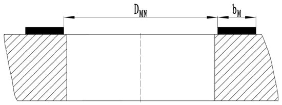
Figure 1.
Classic flat sealing structure for a globe valve.
In Figure 1, the inner diameter of the PCTFE sealing ring is denoted as DMN, while the width of the sealing surface is represented as bm. The design pressure of the valve is indicated by p. The following formula is introduced to calculate the force exerted by the medium at the sealing surface, which is represented as Fn or Fn.
Fn = π/4 (DMN + bM)2 p
The sealing force on the contact surface of the sealing surface can be written as:
where qm represents the sealing surface specific pressure; therefore, the total force on the sealing surface Fa can be written as:
Fm = π/4 (DMN + bM)2 bM qM
Fa = Fn+ Fm = π (DMN + bM) bM qM +π/4 (DMN + bM)2 bM qM
2.2. Material Properties
According to the working conditions of the sealing structure in the globe valve, polychlorotrifluoroethylene (PCTFE) and ethylene propylene diene monomers (EPDMs) were selected as the sealing ring materials for the valve structure. PCTFE is a high-performance engineering plastic with a long-term service temperature range from −200 °C to 150 °C. It possesses unique rigidity, toughness, and excellent low-temperature resistance. It is resistant to various acids, alkalis, oils, and most organic solvents. Its outstanding electrical insulation properties remain unaffected by temperature and humidity within a relatively high temperature range. Additionally, PCTFE exhibits exceptional gas tightness, non-stick surface characteristics, high mechanical strength, and very low water absorption.
As can be seen from Table 1, PCTFE offers excellent cold resistance, high strength and hardness, good dimensional stability, and no tendency for cold flow. Its thermal conductivity is 0.25 W/(m·°C), its coefficient of linear expansion ranges from (9.5~19.6) × 10−5/°C, its tensile strength is 19~20 MPa, its elastic modulus is 1300 MPa, its compressive strength is 50~70 MPa, and its flexural strength is 70 MPa. It can withstand inorganic acids at relatively high temperatures, strong oxidizing agents in saline solutions at lower temperatures, and most organic media at room temperature. When the valve operating pressure is below 25 MPa, PCTFE is an ideal sealing ring material. The specific material properties are shown in the table below:

Table 1.
Comparison of finite element results with different mesh numbers.
The metallic components of the valve are made of stainless steel, with a Young’s modulus of 190,000 MPa and a Poisson’s ratio of 0.3. The material properties of the valve were obtained through experimental testing.
2.3. FE Model Establishment
In ABAQUS 6.14 (Wuxi, China), the finite element model of the valve structure was established based on the actual geometric dimensions and material properties of the components. Key structural parts, including the valve body and sealing ring, were accurately modeled to ensure simulation fidelity. Appropriate mesh controls were applied to critical regions, especially at the contact interfaces, to enhance computational accuracy.
According to the valve sealing design, the finite element models of the sealing structure of polytrifluorochloroethylene (PCTFE) and ethylene propylene diene monomer (EPDM) were established, respectively. The PCTFE sealing material was sealed in the form of a sealing ring, and its main sealing parameter was the compression amount. The EPDM sealing material was sealed in the form of a sealing gasket, and its main sealing parameter was the pressure of the sealing surface. The following analysis will be carried out for the two sealing structures.
Figure 2 illustrates the schematic diagram of the finite element model for the two sealing forms, both of which utilize solid elements. A frictionless contact pair is employed to define the sealing surface. The left PCTFE model is characterized by the material properties listed in the table, with a Poisson’s ratio of 0.38. The material of the right sealing ring is EPDM. Friction is neglected in the calculation process, and the sealing ring is assumed to behave as a hyperplastic material.
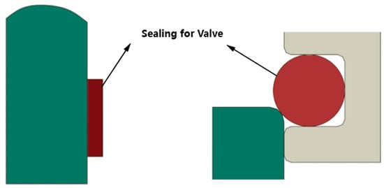
Figure 2.
Two sealing forms and sealing ring schematic diagram.
2.4. Model Simplification and Meshing
This study analyzes the sealing form and mechanical properties of the rubber ring (EPDM). Figure 3 illustrates the sealing structure of the EPDM in the globe valve. It is evident from Figure 3 that, depending on the operational state of the ring, stress concentration occurs in the lower left corner when positioned in the sealing configuration. This phenomenon is attributed to significant deformation resulting from the contact between the hyperelastic material and the metal components. According to the calculated results, the maximum stress value is approximately 4.58 MPa, which remains within safe limits at room temperature and satisfies the sealing requirements.
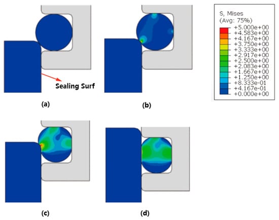
Figure 3.
Analysis of sealing form and mechanical properties of the rubber ring (EPDM) (a–d).
Due to the extremely low temperature affecting the valve, the elastic performance of the sealing ring is significantly diminished under such conditions. Therefore, it is crucial to avoid excessive deformation of the sealing ring during the design process. The accompanying figure illustrates the deformation characteristics of the sealing ring. Figure 4a depicts the process of the sealing ring entering its sealing position, wherein noticeable deformation occurs at the contact points. Figure 4b presents the deformation distribution of the sealing ring during operation, indicating substantial deformation. To ensure optimal sealing performance at extremely low temperatures, it is essential to minimize the large deformations indicated by the red ring in the figure.
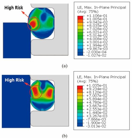
Figure 4.
Damage calculation results of the rubber ring seal (a,b).
The significant deformation of the sealing ring at low temperatures may compromise sealing performance. To address this issue, we redesigned the planar sealing structure for the ultra-low-temperature valve and selected PCTFE as the sealing ring material. Based on the actual installation conditions, we simulated four different axial sealing forces: 720 N, 1260 N, 3170 N, and 7200 N. The simulation results indicate that with an increase in the axial sealing force, the pressure at the sealing contact surface also rises correspondingly. At a sealing force of 720 N, the contact surface pressure is measured at 4.011 MPa. When the sealing force is increased to 1260 N, the contact surface pressure rises to 6.17 MPa. As the sealing force continues to increase to 3170 N, the contact surface pressure reaches 17.5 MPa. At this point, the sealing ring remains in normal working condition, exhibiting a deformation of only 0.003 mm. Further increasing the sealing force to 7200 N results in a contact surface pressure of 39.44 MPa. At this stage, the sealing ring does not experience failure, and the deformation is approximately 0.009 mm.
Furthermore, when using PCTFE as the sealing ring material, according to the previous formula, we introduce the calculation formula of the specific pressure of the sealing surface.
Q = Fa/[π(DMN + bM) bM]
Taking qm = 16.5 MPa, the theoretical pressure is about 40 MPa, which is consistent with the calculation results and meets the performance requirements of the sealing washer.
3. System Description and Testing
3.1. System Principle
Liquid hydrogen valves encompass a diverse range of configurations, including ball valves, butterfly valves, and globe valves. Despite structural variations, all designs incorporate extended bonnets, condensate collection trays, abnormal pressurization prevention mechanisms, cryogenic sealing materials, and thermal insulation systems to ensure operational safety and efficiency in cryogenic environments. Among these features, thermal insulation methodologies impose distinct requirements on testing systems, whereas other components exhibit minimal impact []. Consequently, testing system design must prioritize thermal management approaches as the fundamental engineering criterion.
Two primary thermal insulation methodologies are currently employed in liquid hydrogen valve design: thermal barrier materials and vacuum-jacketed configurations. Material selection for thermal insulation primarily draws upon operational experience with LNG cryogenic valves, favoring economically viable substances exhibiting low thermal conductivity, minimal density, reduced moisture absorption, superior cryogenic performance, and field-application adaptability [,]. Polyurethane foam constitutes the predominant choice in this category. Conversely, vacuum-jacketed liquid hydrogen valves typically omit condensate collection trays and incorporate vacuum-sealed welding flanges on both the valve body and extended bonnet to facilitate on-site installation.
During operational service, the external vacuum layer effectively suppresses heat transfer between the cryogenic internal media and ambient environments. While foam insulation demonstrates significantly lower manufacturing costs compared to vacuum-jacketed systems, its application necessitates labor-intensive installation across entire test piping networks and valve assemblies. When subjected to ultra-cryogenic fluid testing, conventional foam insulation—even when pre-dried and vacuum-preserved—fails to maintain adequate thermal performance. This deficiency introduces measurement artifacts in valve-mounted thermometers and experiences progressive thermal degradation during rewarming phases due to atmospheric moisture absorption. Furthermore, valve replacement mandates simultaneous removal and reinstallation of all integrated foam insulation layers throughout connected piping systems.
Consequently, designs for liquid hydrogen valve test benches must incorporate high-vacuum multilayer insulation systems, wherein cryogenic components—including valves and transfer lines—are housed within evacuated cryostats. Continuous vacuum pumping maintains optimal vacuum integrity within these enclosures. This configuration achieves maximal thermal isolation from ambient environments, significantly reducing cryogen boil-off during testing []. Cryostats may utilize either single-wall vacuum vessels, which offer structural simplicity and operational convenience, or dual-wall vacuum-insulated designs that provide superior thermal performance despite their increased complexity. The upper flange of the cryostat includes a central access port. Test valves undergo bonnet modification with welded adapter plates that precisely match specified dimensions. This design facilitates bolted connections to the interface for straightforward installation and removal, as illustrated in Figure 5. Auxiliary ports integrated into the cryostat lid include purge gas connections, cryogen supply inlets, and corresponding control valves.
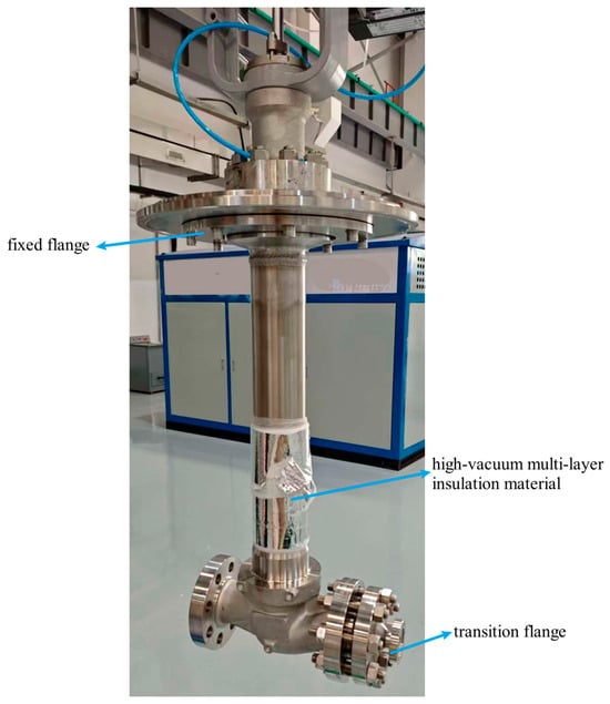
Figure 5.
Liquid hydrogen valve physical drawing.
3.2. Piping System
Typically, as the temperature decreases, the elastic modulus, tensile strength, and yield strength of materials increase. Conversely, the plasticity of materials at low temperatures is influenced by their ductile–brittle transition characteristics. Particularly, below −196 °C, the strength of steel exhibits exponential enhancement. However, as temperatures approach −253 °C, the plasticity of all steels deteriorates significantly. Compared to room temperature conditions, austenitic 304 stainless steel demonstrates reductions of 20–50% in both Charpy V-notch impact energy and lateral expansion []. This degradation heightens the risk of fracture in primary pressure-bearing components of valves, potentially leading to leakage incidents. At temperatures below −253 °C, most steel materials exhibit a drastic reduction in plasticity, indicating the occurrence of a ductile-to-brittle transition under extreme cryogenic conditions. Since low-temperature brittle fracture can severely compromise structural integrity, materials used for piping and pressure-containing valve components in liquid hydrogen test systems must undergo Charpy impact testing at −253 °C to evaluate their low-temperature impact toughness []. Impact toughness is intrinsically linked to the crystalline structure of materials, with face-centered cubic (FCC) metals exhibiting superior performance at low temperatures. Specifically, grades 304 and 316, which are austenitic stainless steels commonly used in cryogenic vessels, exemplify this characteristic []. However, determining the specific grade requires a holistic evaluation of pipe diameter, media pressure and weldability, particularly for cryogenic service applications. As illustrated in Figure 6, vacuum-insulated piping systems—including rigid and corrugated variants—should utilize austenitic stainless steel throughout. All inter-pipe connections should employ either flanged joints or full-penetration butt welds to mitigate fatigue stress accumulation during thermal cycling. Concurrently, expansion compensation elements must be integrated to prevent sealing failure induced by thermal displacement.
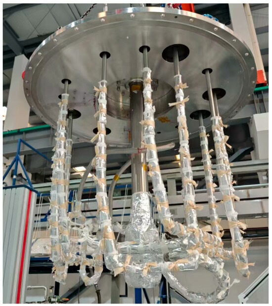
Figure 6.
Internal piping of the liquid hydrogen valve test device.
Within the test system, cryogenic fluid-conveying piping sections are housed inside vacuum chambers with external surfaces enveloped by multilayer insulation (MLI) under high vacuum (≤10−3 Pa). This thermal barrier comprises alternating low-emissivity radiation shields (reflectivity >95%) parallel to cold surfaces and low-thermal-conductivity spacer materials, effectively suppressing heat transfer through radiation, solid conduction, and residual gas conduction. Installation protocols must ensure optimal layer count while maintaining interlayer separation—critical to preventing compression-induced increases in solid conduction or vacuum impedance that elevate residual gas conduction. Extended piping segments beyond the vacuum chamber contain predominantly vaporized media still maintained at cryogenic temperatures (−200 °C), creating condensation risks for environmental oxygen (boiling point −183 °C). Frictional ignition hazards exist between liquid oxygen microdroplets and solidified water/CO2 particulates. The safety mitigation strategy employs vacuum-jacketed encapsulation with integrated electrical heaters, elevating media temperature to ambient-condition helium gas for metered discharge via flowmeters/bubble counters. Transition sections utilize polyurethane foam insulation (thermal conductivity ≤ 0.025 W/m·K).
3.3. Selection of Test Media
Chinese National Standards Valves for liquid hydrogen—General specification requires that cryogenic performance testing employ internal cooling methods using test media including liquid hydrogen, liquid helium, or their saturated vapors. Although the energy law of the People’s Republic of China, issued by the National Energy Administration, incorporated hydrogen into the national energy management framework, hydrogen remains classified as a hazardous chemical under current regulations []. Historically deployed as an industrial feedstock in petroleum refining, metallurgy, and coal chemical sectors—where consumption occurs at fixed, remote sites with controllable risks—hydrogen faces implementation challenges in civilian applications. Consequently, this test system utilizes liquid helium as the cooling and test medium.
Internal cooling methodology for cryogenic valve testing requires direct cryogen injection into the valve body to minimize heat exchange between the precooled valve and test fluid []. While cryogenic pumps could theoretically deliver media at the valve’s maximum allowable working pressure (MAWP), continuous cycling tests for high-pressure, large-bore valves impose prohibitive demands on pump performance, substantially increasing system complexity. Therefore, a cryogenic heat exchanger is installed upstream of the test valve, wherein coiled tubing immersed in liquid nitrogen cools helium gas to 77 K. However, the resultant 50 K temperature differential between the 77 K helium and the precooled valve body accelerates heat ingress. To mitigate this, a secondary liquid helium dewar may be added downstream, containing immersion-cooled coiled tubing with liquid helium replenishment ports. This cascaded system further cools the helium to 20~30 K before valve injection. Considering temporal and economic constraints, the present test system implements only the liquid nitrogen heat exchanger as the primary cooling stage.
3.4. Test Procedure and Results
Ultra-cryogenic environments induce material contraction and embrittlement, enlarging clearances between valve sealing surfaces and resulting in elevated leakage rates for valves that demonstrate zero leakage at ambient or liquid nitrogen temperatures when tested in liquid hydrogen conditions. Consequently, cryogenic sealing tests constitute an essential validation methodology for assessing liquid hydrogen valve performance under operational cryogenic conditions []. Valve leakage manifests as two distinct types: internal leakage occurring between the stem closure member and seat sealing surface, and external leakage through the stem-packing interface or body–bonnet joint. While internal leakage compromises globe valve functionality, external leakage permits hazardous media discharge into the atmosphere, with the former subject to permissible thresholds whereas the latter remains strictly prohibited.
The experimental methodology employs a liquid hydrogen valve test system utilizing liquid helium substitution (technical parameters detailed in Table 2; system schematic shown in Figure 7. The test procedure commences by placing the valve under examination in a vacuum chamber evacuated to a pressure range of 10−3 to 10−4 Pa. The 20 K qualification process involves sequential cooling phases: initially, liquid nitrogen is continuously circulated through the precooling port until the valve temperatures stabilize near 77 K for a duration of 5 to 10 min. This is followed by cryogenic helium purging, which serves to eliminate residual nitrogen and oxygen, thereby preventing the formation of particulates that could compromise the sealing integrity. Subsequently, liquid helium is introduced through the inlet while simultaneously recovering the effluent helium gas. The stabilization of temperature at 20 K triggers the transition to 99.999% purity cryogenic helium, which is utilized for the final verification of seal integrity. Following the closure of the inlet valve, the quantification of leak rates is conducted through terminal flowmeter measurements to assess internal leakage, alongside sniffer-mode helium mass spectrometer detection at the body-bonnet joints to evaluate external leakage.
Table 2.
Technical parameters of the valve under test.
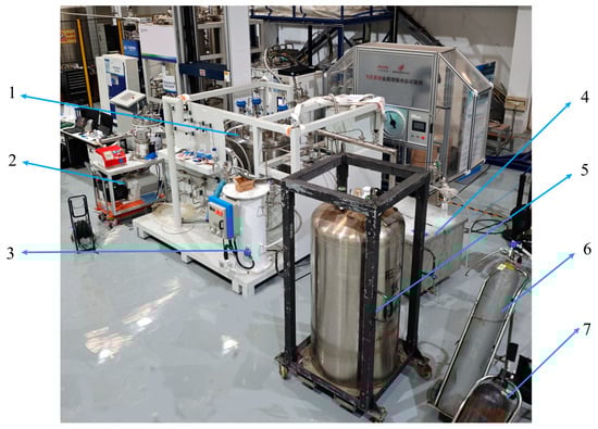
Figure 7.
Physical diagram of the liquid hydrogen valve test device: (1) Vacuum chamber; (2) vacuum pump, (3) heat exchanger, (4) test medium cold box, (5) liquid nitrogen tank, (6) helium gas source, and (7) nitrogen gas source.
Figure 8 shows the thermal evolution of the valve body during testing, progressing from initial cooling with liquid nitrogen to an equilibrium at 77 K. It experiences a transient rise to 85 K during helium purging and subsequently reaches a minimum temperature of 10 K during liquid helium injection. After achieving thermal stabilization, characterized by fluctuations within ±0 K over a period of two minutes, the injection of liquid helium ceases, and sealing tests commence using 77 K helium. It is important to note that Figure 7 illustrates qualitative thermal trends rather than precise chronothermal records.
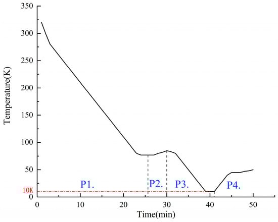
Figure 8.
Liquid hydrogen valve test temperature variation curve: (P1) Liquid nitrogen pre-cooling, (P2) liquid nitrogen pre-cooling, (P3) liquid helium cooling, and (P4) seal testing.
Background interference from helium elevates initial leak readings, necessitating the activation of the terminal vent during the initiation of tests to evacuate residual helium. Following the prescribed duration, vent closure coincides with activation of accumulation-mode leak detectors and alcohol bubble meters, with stabilized mass spectrometer recordings providing definitive measurements. Methodological enhancement through helium precooling to 20 K via Gifford–McMahon (GM) cryocoolers prior to valve introduction effectively suppresses thermal transients during sealing tests, thereby ensuring measurement fidelity by mitigating temperature-induced variability in leakage quantification.
4. Conclusions
This study developed a liquid hydrogen valve test system in accordance with the Chinese National Standards Valves for liquid hydrogen—General specification. This testing platform utilizes liquid helium instead of liquid hydrogen for cryogenic performance testing, thereby mitigating the safety risks associated with liquid hydrogen in a similar low-temperature environment. Additionally, the platform features a forward-looking, expandable design, which reserves space for potential future liquid hydrogen testing. By integrating with liquid hydrogen storage tanks and pumps, the system will employ real liquid hydrogen as the working medium for cryogenic validation, allowing for an in-depth exploration of the impact mechanisms of liquid hydrogen’s physical properties on valve sealing structures. This design offers an advanced technical validation platform for investigating the cryogenic adaptability of key components within liquid hydrogen systems. In the following, some conclusions are drawn from this work:
- (1)
- The EPDM sealing ring is efficient with acquired deformation, however, when the temperature decreases, the sealing deformation distribution is observed to be considerably large in the contact area. Meanwhile, when using PCTFE as the sealing ring material and redesigning the sealing structure as plate sealing, the material degradation risk is reduced. Theoretical sealing formulas were introduced to calculate the sealing pressure; furthermore, FE simulation was performed, showing that PCTFE sealing was not damaged under 39.44 MPa pressure with a deformation of 0.009 mm.
- (2)
- The system accommodates pipeline valves below DN100 and cylinder valves for liquid hydrogen storage vessels. With a maximum test pressure of Class 600, it effectively covers conventional liquid hydrogen valve specifications and pressure ratings.
- (3)
- The test platform utilizes a hybrid cooling approach combining liquid nitrogen pre-cooling with liquid helium internal cooling. This methodology achieves target liquid hydrogen temperatures within 1–2 h—significantly faster than GM cryocooler-based systems. An integrated liquid helium recovery system further ensures cost-effectiveness during testing.
- (4)
- Test results demonstrate that proper selection of soft-seal structures combined with application of specified tightening torques ensures that leakage rates at design temperatures meet requirements. Experimental data show consistent alignment with numerical simulations.
Author Contributions
Conceptualization, Z.M. and S.J.; methodology, Z.M.; software, Z.M.; formal analysis, Z.M.; resources, M.Y.; data curation, Z.M.; writing—original draft preparation, Z.M.; writing—review and editing, F.L. All authors have read and agreed to the published version of the manuscript.
Funding
This research was funded by the National Key Research and Development Program of China (No. 2024YFF0620002); the Science and Technology Project of State Administration for Market Regulation (2023MK041); the Key Research and Development Project of Jiangsu Province (BE2022001-5).
Data Availability Statement
The original contributions presented in this study are included in the article. Further inquiries can be directed to the corresponding author.
Conflicts of Interest
The authors declare no conflicts of interest.
References
- Dawood, F.; Anda, M.; Shafiullah, G.M. Hydrogen Production for Energy: An Overview. Int. J. Hydrogen Energy 2020, 45, 3847–3869. [Google Scholar] [CrossRef]
- Abe, J.O.; Popoola, A.P.I.; Ajenifuja, E.; Popoola, O.M. Hydrogen Energy, Economy and Storage: Review and Recommendation. Int. J. Hydrogen Energy 2019, 44, 15072–15086. [Google Scholar] [CrossRef]
- Rampai, M.M.; Mtshali, C.B.; Seroka, N.S.; Khotseng, L. Hydrogen Production, Storage, and Transportation: Recent Advances. RSC Adv. 2024, 14, 6699–6718. [Google Scholar] [CrossRef]
- Zhang, Y.; Jia, Z.; Yuan, Z.; Yang, T.; Qi, Y.; Zhao, D. Development and Application of Hydrogen Storage. J. Iron Steel Res. Int. 2015, 22, 757–770. [Google Scholar] [CrossRef]
- Aziz, M. Liquid Hydrogen: A Review on Liquefaction, Storage, Transportation, and Safety. Energies 2021, 14, 5917. [Google Scholar] [CrossRef]
- Ustolin, F.; Campari, A.; Taccani, R. An Extensive Review of Liquid Hydrogen in Transportation with Focus on the Maritime Sector. J. Mar. Sci. Eng. 2022, 10, 1222. [Google Scholar] [CrossRef]
- Hossain Bhuiyan, M.M.; Siddique, Z. Hydrogen as an Alternative Fuel: A Comprehensive Review of Challenges and Opportunities in Production, Storage, and Transportation. Int. J. Hydrogen Energy 2025, 102, 1026–1044. [Google Scholar] [CrossRef]
- Ajanovic, A.; Sayer, M.; Haas, R. The Economics and the Environmental Benignity of Different Colors of Hydrogen. Int. J. Hydrogen Energy 2022, 47, 24136–24154. [Google Scholar] [CrossRef]
- Yin, L.; Ju, Y. Review on the Design and Optimization of Hydrogen Liquefaction Processes. Front. Energy 2020, 14, 530–544. [Google Scholar] [CrossRef]
- Kim, J.H.; Park, D.K.; Kim, T.J.; Seo, J.K. Thermal-Structural Characteristics of Multi-Layer Vacuum-Insulated Pipe for the Transfer of Cryogenic Liquid Hydrogen. Metals 2022, 12, 549. [Google Scholar] [CrossRef]
- Tiwari, S.; Pekris, M.J.; Doherty, J.J. A Review of Liquid Hydrogen Aircraft and Propulsion Technologies. Int. J. Hydrogen Energy 2024, 57, 1174–1196. [Google Scholar] [CrossRef]
- Andersson, J.; Grönkvist, S. Large-Scale Storage of Hydrogen. Int. J. Hydrogen Energy 2019, 44, 11901–11919. [Google Scholar] [CrossRef]
- Zhang, C.; Shao, Y.; Shen, W.; Li, H.; Nan, Z.; Dong, M.; Bian, J.; Cao, X. Key Technologies of Pure Hydrogen and Hydrogen-Mixed Natural Gas Pipeline Transportation. ACS Omega 2023, 8, 19212–19222. [Google Scholar] [CrossRef]
- Witkowski, A.; Rusin, A.; Majkut, M.; Stolecka, K. Analysis of Compression and Transport of the Methane/Hydrogen Mixture in Existing Natural Gas Pipelines. Int. J. Press. Vessel. Pip. 2018, 166, 24–34. [Google Scholar] [CrossRef]
- Wijayanta, A.T.; Oda, T.; Purnomo, C.W.; Kashiwagi, T.; Aziz, M. Liquid Hydrogen, Methylcyclohexane, and Ammonia as Potential Hydrogen Storage: Comparison Review. Int. J. Hydrogen Energy 2019, 44, 15026–15044. [Google Scholar] [CrossRef]
- Omori, K.M.; Mazon-Cartagena, R.; Fernández-Torres, M.J.; Caballero, J.A.; Ravagnani, M.A.S.S.; Pavão, L.V.; Costa, C.B.B. Sensitivity Analysis in Simple Cycles for Hydrogen Liquefaction. Processes 2025, 13, 3076. [Google Scholar] [CrossRef]
- Shen, J.; Liu, Y.; Hao, Y.; Li, F.; Zhou, H. Study on the Thermodynamic Behavior of Large Volume Liquid Hydrogen Bottle Under the Coupling of Different Motion States and Operational Parameters. Processes 2025, 13, 3340. [Google Scholar] [CrossRef]
- Cava, C.; Gagliardi, G.G.; Piscolla, E.; Borello, D. Techno-Economic Analysis of Hydrogen Transport via Truck Using Liquid Organic Hydrogen Carriers. Processes 2025, 13, 1081. [Google Scholar] [CrossRef]
- Qu, J.; Zhou, T.; Zhao, H.; Deng, J.; Luo, Z.; Cheng, F.; Wang, R.; Chen, Y.; Shu, C. Risk Analysis of Hydrogen Leakage at Hydrogen Producing and Refuelling Integrated Station. Processes 2025, 13, 437. [Google Scholar] [CrossRef]
- Sotoodeh, K. A Review of Valve Stem Sealing to Prevent Leakage from the Valve and Its Effect on Valve Operation. J. Fail. Anal. Preven. 2021, 21, 9–16. [Google Scholar] [CrossRef]
- Gorash, Y.; Dempster, W.; Nicholls, W.D.; Hamilton, R.; Anwar, A.A. Study of Mechanical Aspects of Leak Tightness in a Pressure Relief Valve Using Advanced FE-Analysis. J. Loss Prev. Process Ind. 2016, 43, 61–74. [Google Scholar] [CrossRef]
- Lin, Z.; Yu, L.; Hua, T.; Jin, Z.; Qian, J. Seal Contact Performance Analysis of Soft Seals on High-Pressure Hydrogen Charge Valves. J. Zhejiang Univ. Sci. A 2022, 23, 247–256. [Google Scholar] [CrossRef]
- Cao, C.; Zhao, J.; Li, G.; Jin, X.; Cao, Z. Dynamic and Static Sealing Performance of Elastic Check Valve Spool. J. Eng. 2019, 2019, 28–31. [Google Scholar] [CrossRef]
- Barbosa Teles, D.; Da Silva Gehlen, G.; Lasch, G.; Yesukai De Barros, L.; Muniz Dias, Y.; Neis, P.D.; Ferreira, N.F.; De Souza, A.J. Tribological Investigation of Contact Pairs Applied in Metallic Gate Valve Seals for Onshore Application. Wear 2023, 523, 204750. [Google Scholar] [CrossRef]
- Sreekanth, N.; Sankaran, S.; Kenned, J.J. Development of Soft Seal and Experimental Investigation of Soft Seated Safety Relief Valves for Cryogenic Applications. Cryogenics 2025, 146, 101005. [Google Scholar] [CrossRef]
- Zhang, N.; Li, Q.; Li, Q.; Hu, Z.; Hu, K. Seat Tightness of Pneumatic Cryogenic Control Valve. Sci. China Technol. Sci. 2013, 56, 2066–2069. [Google Scholar] [CrossRef]
- Zhang, G.; Wang, W.W.; Wu, Z.Y.; Chen, D.S.; Kim, H.D.; Lin, Z. Effect of the Opening Degree on Evolution of Cryogenic Cavitation through a Butterfly Valve. Energy 2023, 283, 128543. [Google Scholar] [CrossRef]
- Li, S.; Zheng, M.; Wang, Y.; Yang, L.; Ma, T. Multi-Objective Optimization Design of Double Resilient Groove Metal Seat for Ball Valve in Liquid Hydrogen Receiving Stations. J. Braz. Soc. Mech. Sci. Eng. 2024, 46, 34. [Google Scholar] [CrossRef]
- Lyu, B.; Xu, D.; Li, L.; Nishimura, A.; Liu, H.; Zhang, H.; Wang, T.; Huang, R.; Huang, C. A 20 K Cryogen-Free Leak Detection System for Cryogenic Valves by Using a GM Cryocooler. Cryogenics 2021, 117, 103332. [Google Scholar] [CrossRef]
- Townsend, A.; Mishra, R. Design and Development of a Helium Injection System to Improve External Leakage Detection during Liquid Nitrogen Immersion Tests. Cryogenics 2016, 79, 17–25. [Google Scholar] [CrossRef]
- Pinho, J.; Peveroni, L.; Vetrano, M.R.; Buchlin, J.-M.; Steelant, J.; Strengnart, M. Experimental and Numerical Study of a Cryogenic Valve Using Liquid Nitrogen and Water. Aerosp. Sci. Technol. 2019, 93, 105331. [Google Scholar] [CrossRef]
- Davies, E.; Ehrmann, A.; Schwenzfeier-Hellkamp, E. Safety of Hydrogen Storage Technologies. Processes 2024, 12, 2182. [Google Scholar] [CrossRef]
- ASTM D638; Standard Test Method for Tensile Properties of Plastics. ASTM International: West Conshohocken, PA, USA, 2022.
- ASTM D785; Standard Test Method for Rockwell Hardness of Plastics and Electrical Insulating Materials. ASTM International: West Conshohocken, PA, USA, 2023.
- ASTM D2240; Standard Test Method for Rubber Property—Durometer Hardness. ASTM International: West Conshohocken, PA, USA, 2021.
- ASTM D695; Standard Test Method for Compressive Properties of Rigid Plastics. ASTM International: West Conshohocken, PA, USA, 2023.
- ASTM D790; Standard Test Methods for Flexural Properties of Unreinforced and Reinforced Plastics and Electrical Insulating Material. ASTM International: West Conshohocken, PA, USA, 2017.
- ASTM D792; Standard Test Methods for Density and Specific Gravity (Relative Density) of Plastics by Displacement. ASTM International: West Conshohocken, PA, USA, 2020.
- ASTM D570; Standard Test Method for Water Absorption of Plastics. ASTM International: West Conshohocken, PA, USA, 2022.
- Tietze, V.; Luhr, S.; Stolten, D. Bulk Storage Vessels for Compressed and Liquid Hydrogen. In Hydrogen Science and Engineering: Materials, Processes, Systems and Technology; Stolten, D., Emonts, B., Eds.; Wiley: Hoboken, NJ, USA, 2016; pp. 659–690. ISBN 978-3-527-33238-0. [Google Scholar]
- Xu, X.; Xu, H.; Zheng, J.; Chen, L.; Wang, J. A High-Efficiency Liquid Hydrogen Storage System Cooled by a Fuel-Cell-Driven Refrigerator for Hydrogen Combustion Heat Recovery. Energy Convers. Manag. 2020, 226, 113496. [Google Scholar] [CrossRef]
- Ding, Y.; Shao, D.; Jin, S.; Yu, M.; Wang, Y.; Jiang, L. Numerical Study on Composite Multilayer Insulation Material for Liquid Hydrogen Storage. Coatings 2024, 14, 1417. [Google Scholar] [CrossRef]
- Zheng, C.; Yu, W. Effect of Low-Temperature on Mechanical Behavior for an AISI 304 Austenitic Stainless Steel. Mater. Sci. Eng. A 2018, 710, 359–365. [Google Scholar] [CrossRef]
- Ustolin, F.; Paltrinieri, N.; Berto, F. Loss of Integrity of Hydrogen Technologies: A Critical Review. Int. J. Hydrogen Energy 2020, 45, 23809–23840. [Google Scholar] [CrossRef]
- Qiu, Y.; Yang, H.; Tong, L.; Wang, L. Research Progress of Cryogenic Materials for Storage and Transportation of Liquid Hydrogen. Metals 2021, 11, 1101. [Google Scholar] [CrossRef]
- Aasadnia, M.; Mehrpooya, M. Large-Scale Liquid Hydrogen Production Methods and Approaches: A Review. Appl. Energy 2018, 212, 57–83. [Google Scholar] [CrossRef]
Disclaimer/Publisher’s Note: The statements, opinions and data contained in all publications are solely those of the individual author(s) and contributor(s) and not of MDPI and/or the editor(s). MDPI and/or the editor(s) disclaim responsibility for any injury to people or property resulting from any ideas, methods, instructions or products referred to in the content. |
© 2025 by the authors. Licensee MDPI, Basel, Switzerland. This article is an open access article distributed under the terms and conditions of the Creative Commons Attribution (CC BY) license (https://creativecommons.org/licenses/by/4.0/).