Abstract
Drilling trajectory closed-loop control in directional drilling is a key technology for achieving high-precision drilling. However, due to the complex geological conditions, and engineering limitations of drilling tools, traditional control methods of drilling often face challenges, such as error accumulation, response delays, and control instability. To address these issues, this paper proposes an intelligent closed-loop steering method based on online adaptive optimization. The core of this method lies in the construction of an integrated “perception–optimization–execution” intelligent steering framework. First, real-time attitude feedback is used to accurately perceive trajectory deviations. Then, an optimization model is triggered, aiming to minimize deviations under the dogleg severity constraint, and genetic algorithms are employed to dynamically calibrate the PID controller online, effectively eliminating error accumulation. Finally, based on the optimization results, real-time calculations of tool face angle and steering tool force are performed to ensure precise execution of steering commands. Simulation results show that, compared to the traditional PID and PID-APF methods, the proposed method demonstrates significant advantages in trajectory control accuracy and wellbore quality. Under noise-free conditions, the normal distance accuracy improves by 88.89% and 34.02%, respectively, and dogleg severity is reduced by 6.30% and 5.81%. Under noise interference, the normal distance accuracy improves by 56.73% and 54.97%, respectively, and dogleg severity is reduced by 23.38% and 4.85%. In conclusion, the proposed intelligent closed-loop control method not only significantly enhances the system’s real-time response capability and control precision but also exhibits stronger robustness, with broad potential for engineering applications.
1. Introduction
As the demand unconventional oil and gas resources grows, the well trajectory design and control become more and more complex. Geometric guidance control, which adjusts the downhole drilling tool attitude in real-time, is essential for accurate drilling and efficient trajectory tracking [,]. However, challenges persist, including the impact of dogleg severity on trajectory smoothness [,,] and error accumulation during long drilling intervals [,,]. These factors can lead to deviations in the trajectory and instability in the control system.
Proportional–Integral–Derivative (PID) controllers are widely used in fields such as robotics [,], vehicles [,], and drones [] for their simple structure, adjustable parameters, and fast response [,]. In automatic wellbore trajectory control, although existing studies have effectively reduced the impact of disturbances and uncertainties, overshoot still occurs in the tracking of inclination and azimuth []. Thus, an adaptive mechanism is needed to dynamically adjust control parameters and mitigate performance degradation due to error fluctuations []. For example, Alvarado-Silva et al. [] proposed a gain-scheduling PID method that improves accuracy but responds poorly to unaddressed conditions or sudden disturbances. To enhance robustness, Laib et al. [] and Zhang et al. [] combined fuzzy logic with PID control to achieve dynamic gain adjustment. However, during actual drilling, if operational conditions change (such as weight on bit fluctuations, variations in rock properties, or unstable mud flow) or abnormal situations occur (such as operator errors or equipment failures), the controller is unable to dynamically optimize parameters based on the new state, leading to slower response times and reduced control accuracy.
In summary, the current intelligent control methods still have the following limitations: (1) Although existing PID control strategies have been improved by incorporating fuzzy control and gain scheduling, they still lack the ability for rapid adaptive adjustment while ensuring control accuracy. (2) The existing control strategies mainly focus on adjusting the output of the inclination and azimuth angles. However, these output parameters typically do not provide drilling engineers with the key operational information they need, such as tool face angle and steering tool force, which affects the efficiency and accuracy of decision-making.
This study proposes an intelligent steering method based on adaptive online optimization of PID parameters to address the identified issues. The method dynamically adjusts controller parameters based on real-time downhole conditions, improving trajectory control accuracy and stability. It uses a genetic algorithm to trigger PID parameter optimization when the drilling trajectory deviates beyond a threshold, ensuring smooth trajectory correction. By combining real-time inclination and azimuth data, the method predicts steering tool force and tool face angle, offering intuitive operational guidance and enhancing system practicality. The main innovations of this study are as follows:
- (1)
- This study proposes an intelligent closed-loop control method based on online adaptive optimization, which can quickly and dynamically adjust PID control parameters while ensuring control accuracy. This method effectively addresses the issues of error accumulation, response delay, and control instability.
- (2)
- This study proposes a PID parameter optimization model centered on dogleg severity constraints, with online dynamic calibration achieved through a genetic algorithm. This model minimizes trajectory deviation while ensuring trajectory smoothness and precise tracking.
- (3)
- This study develops a real-time control output module, which accurately calculates tool face angle and steering tool force based on real-time attitude data. This module provides intuitive and efficient operational guidance, offering accurate manual intervention solutions for field operators.
The paper is structured as follows: Section 2 presents the proposed control method. Section 3 provides a detailed description of the geological characteristics of the Luzhou well and the parameter settings for the simulation tests. Section 4 discusses the historical simulation verification based on field data. Section 5 presents the discussion of this study, and Section 6 concludes with future research directions.
2. Methodology
2.1. Framework of This Research
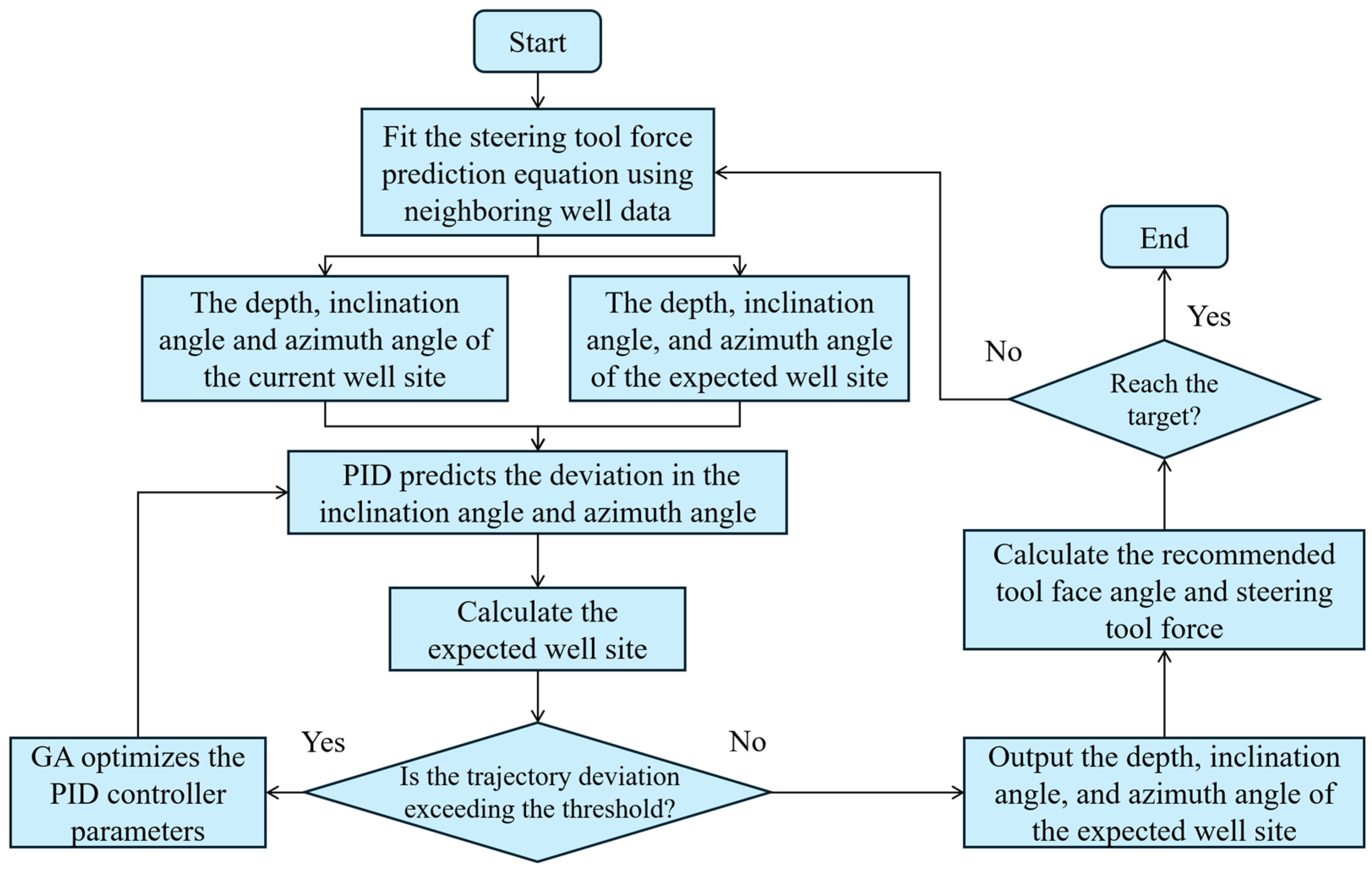
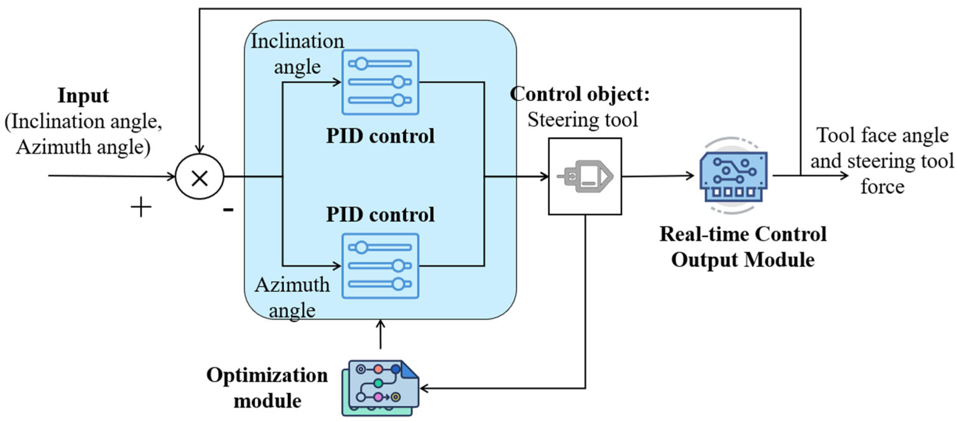
The proposed intelligent steering method consists of three core components, as shown in Figure 1: (1) a PID control mechanism based on three-dimensional intelligent steering; (2) an online PID parameter optimization mechanism based on a genetic algorithm; (3) a control output mechanism utilizing real-time attitude data.
Figure 1.
Architecture diagram of the proposed method.
2.2. PID Control Mechanism Based on Three-Dimensional Intelligent Steering
In intelligent directional drilling, the attitude of the steering tool plays a decisive role in trajectory control accuracy []. The attitude is typically defined by the inclination angle () and azimuth angle (). To ensure that the steering tool’s trajectory aligns with the preset path, this study proposes a PID control mechanism based on attitude error feedback. The mechanism uses real-time inclination and azimuth data as inputs, with the attitude error driving the output control signals, thereby adjusting the steering tool’s motion direction.
In the proposed control method, the steering tool’s attitude adjustment employs a dual-channel independent PID control strategy, which corresponds to the control tasks of the inclination and azimuth angles. Specifically, the system constructs two independent PID controllers to handle the attitude deviations of the steering tool in the vertical and horizontal directions. It is important to note that this dual-channel control design does not merely stack two PID controllers, but instead is based on the differences in physical response, dynamic characteristics, and control sensitivity between the inclination and azimuth angles.
In this method, represents the current position of the drilling tool, while represents the expected position the tool is intended to reach. The corresponding expected attitude is calculated using the following formulas:
where and represent the expected inclination angle and azimuth angle, respectively, between the current position and the expected position, with the unit in degrees (°). When the PID controller obtains the current state , the attitude error can be defined as:
where represents the deviation between the expected inclination angle and the actual inclination angle, in degrees (°), and represents the deviation between the expected azimuth angle and the actual azimuth angle, in degrees (°). represents Gaussian noise with a mean of 0 and a variance of . It should be noted that Equation (3) represents the attitude error without considering the influence of noise. However, in actual drilling operations, trajectory control is often affected by various factors, such as attitude measurement noise, weight on bit fluctuations, and formation heterogeneity. To simulate the effect of noise in the real drilling process, we introduce Gaussian white noise into the PID control module, as shown in Equation (4).
Based on this, two independent PID controllers are established to control the inclination angle and azimuth angle. The control signals are given by:
where , and are the proportional, integral, and derivative gains for the inclination angle, respectively, and , and are the corresponding gains for the azimuth angle. and represent the control signals that correct the deviations in pitch angle and azimuth angle, respectively.
It should be noted that, in actual drilling operations, the adjustment of the inclination angle and azimuth angle is physically coupled, meaning that adjusting one angle typically affects the other. To reduce this coupling effect, this study adopts a step-by-step control approach, where the inclination angle is adjusted first, followed by the adjustment of the azimuth angle. This approach effectively minimizes the mutual interference between the two angles. Furthermore, since the control sampling time is relatively short and the rate of change in the inclination angle and azimuth angle during each iteration is small, this step-by-step control strategy is feasible. It ensures control accuracy while avoiding excessive interference.
In order to ensure that the dogleg severity (DLS) during the drilling process remains within the specified maximum limit, this study proposes a posture adjustment control mechanism for handling super-limit DLS. This mechanism adjusts the azimuth angle and inclination angle smoothly to avoid large posture changes that could destabilize the system. When the DLS exceeds the limit, the system applies a smooth adjustment ratio () to limit the adjustment range of the azimuth and inclination angles. The smooth adjustment ratio is calculated as follows:
where and represent the current dogleg angle and the maximum allowed DLS, respectively. Based on this, the formulas for the smooth adjustment of the azimuth and inclination angles are given by:
where and represent the azimuth and inclination angles measured by the PID controller in the previous iteration. and are the azimuth and inclination angles measured by the PID controller at the current time, and and are the adjusted azimuth and inclination angles.
2.3. Online PID Parameter Optimization Mechanism Based on Genetic Algorithm
During the drilling process, trajectory deviations accumulate progressively with increasing depth. If the PID controller parameters are not adaptively adjusted, the drilling direction will gradually diverge from the designed trajectory. To address this limitation, this study proposes an online adjustment mechanism based on a genetic algorithm for optimizing PID parameters.
For the optimization objective, this study focuses on calculating the deviation between the actual trajectory and the preset trajectory, particularly in the region through which the guiding tool will pass. To quantify this objective, the mathematical expression for trajectory deviation is as follows:
where represents the current position of the drilling tool, and represents the expected position the drilling tool is intended to reach. represents the deviation between the actual trajectory and the preset expected trajectory. The optimization objective () is to minimize this trajectory deviation, which is defined as:
where represents the total number of trajectory positions that the drilling path will pass through.
In addition, to ensure trajectory smoothness, DLS is introduced as a constraint to regulate wellbore curvature [,]. Under this constraint, the wellbore curvature must not exceed the maximum allowable DLS value . The calculation of DLS can be expressed as follows:
where and represent the inclination angles at two adjacent positions during the drilling process. and represent the azimuth angles at the two adjacent positions. is the dogleg angle between the two positions. is the distance between the two adjacent positions.
Finally, combining the optimization objective with the constraint, the optimization problem is formulated as the following single-objective optimization problem:
where represents the PID control strategy parameters proposed in this study, which are to be optimized.
Genetic algorithms (GAs) are a type of global optimization method that can effectively search large solution spaces, seeking the global optimum and avoiding local optima that may exist in traditional optimization methods []. In this study, the study selects a classical GA as the optimization method. For this purpose, this study selects the classical GA as the optimization algorithm. In this study, the main goal of the GA is to obtain a feasible solution through a global search mechanism to effectively constrain the drilling trajectory deviation, rather than strictly finding the globally optimal PID parameters. The goal is to ensure that the normal distance between the drilling trajectory and the preset trajectory remains within the set threshold. To improve the response speed of the GA in optimizing PID parameters, this study has made improvements to the GA process for optimizing PID parameters, as outlined below:
- (1)
- Trigger mechanism improvement: The GA is triggered to run only when the normal distance between the drilling trajectory and the preset trajectory exceeds the threshold, rather than continuously optimizing online, which significantly reduces the computation frequency.
- (2)
- Optimization range reduction: When trajectory deviation occurs, the algorithm selects only a certain range of preset trajectory points near the current drilling position (50 points are selected in this study) for optimization, in order to reduce the computational load.
- (3)
- Early termination strategy: During the optimization process, once a PID parameter causes the normal distance between the predicted trajectory and the preset trajectory to be smaller than the threshold, the optimization is terminated early and the parameter is output, thus avoiding unnecessary computations.
2.4. Control Output Mechanism Based on Real-Time Attitude Data
In actual drilling operations, engineers typically control the drilling direction by adjusting the steering tool force and tool face angle []. However, traditional control methods mainly rely on human experience, which can be easily influenced by human factors. To enhance the controllability and automation of the operation, this study proposes a control quantity output mechanism based on real-time attitude data. This mechanism calculates the required steering tool force and tool face angle based on the current and next positions, inclination angle, and azimuth, thereby enabling the automation of the drilling operation.
To determine the required steering tool force, this study constructs a mathematical relationship model between the DLS and the required steering tool force based on the drilling data from neighboring wells. The mathematical expression is as follows:
where represents the mapping relationship between and the required steering tool force . The fitting results of the steering tool force and DLS mapping function can be found in Appendix A.
In the drilling trajectory control process, the calculation of the tool face angle depends on the changes in the posture of the steering tool. The dogleg angle can be calculated using Equation (12). Based on this, the tool face angle can be calculated using the following formula:
where and represent the current inclination angle and the expected inclination angle, respectively.
2.5. Procedure of This Method
Figure 2 presents a detailed flowchart of the proposed control method. First, a mathematical model to predict the required steering tool force is fitted using drilling data from neighboring wells. Then, the well depth, inclination angle, and azimuth of the current drilling trajectory are obtained and compared with the preset expected well site, followed by the use of a PID model to predict the next expected drilling position. If the normal distance between the expected drilling position and the preset trajectory exceeds the set threshold, the system will use a GA to optimize the PID controller parameters until the trajectory deviation is less than the threshold. Once the normal distance of the expected drilling position is within the threshold, the system outputs the well depth, inclination angle, and azimuth of that position, thus calculating the required tool face angle and steering tool force. If the drilling trajectory has not yet reached the target zone, the above process is repeated until the drilling trajectory reaches the target zone.
Figure 2.
Flowchart of the proposed method.
3. Geological Characteristics and Simulation Setup
3.1. Stratigraphic Characteristics of Luzhou Block
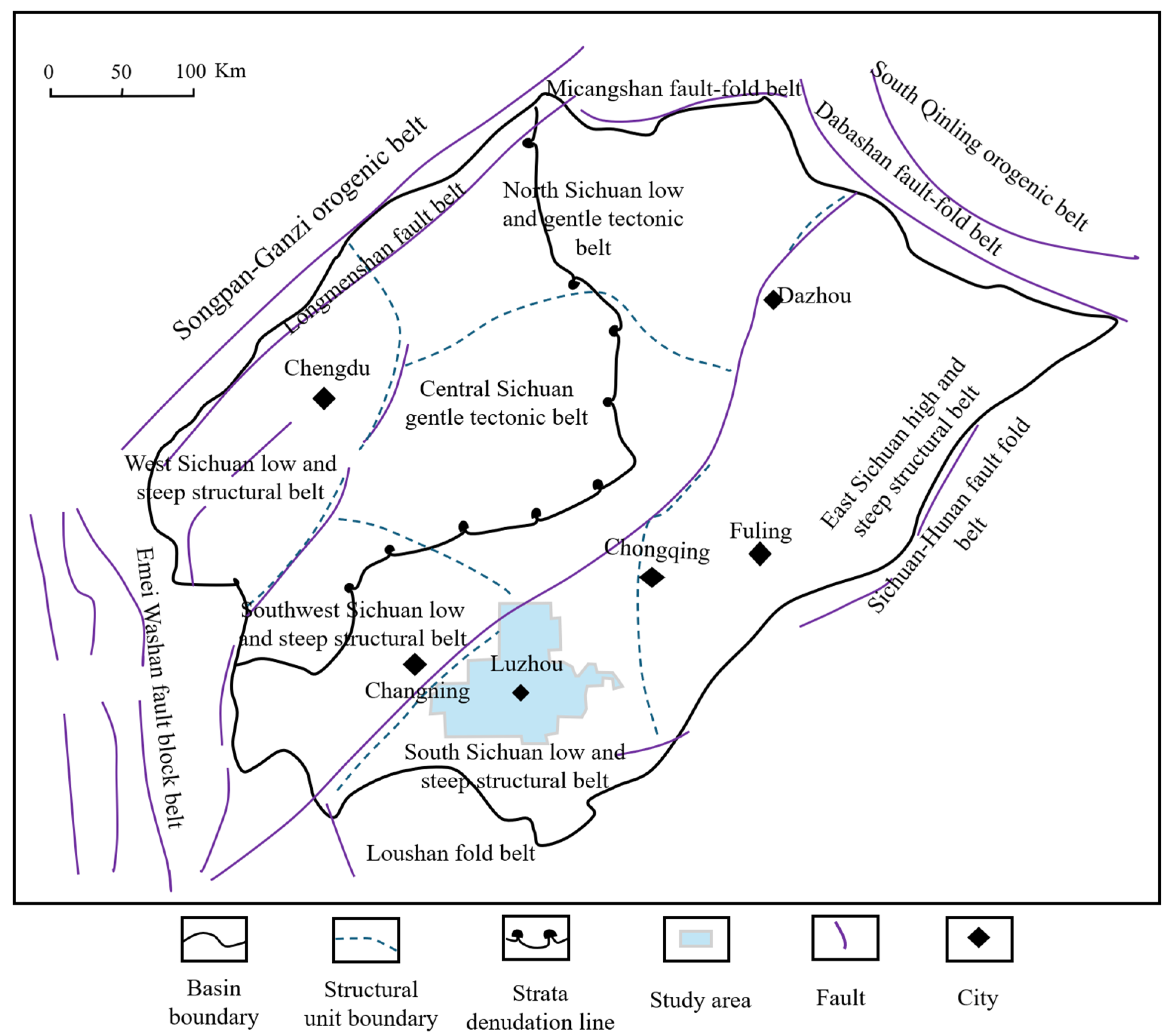
This study uses the wellbore trajectory data of a well in the Luzhou block as a verification object. The study area is located in the southern Sichuan Basin’s Luzhou block, geologically be-longing to the low-steep structural belt of southern Sichuan, situated on the southern side of the central Sichuan paleo-uplift [], as shown in Figure 3. The geological structure of the region is formed by base fault activities from deep to shallow layers, predominantly composed of fold structures controlled by concealed faults [].
Figure 3.
Geological distribution of Luzhou block.
Due to practical limitations, this study is validated based on partial drilling data from a single well, which is located in the Longmaxi Formation. The formation consists of mudstone, silty mudstone, and shale. In addition, the selected wellbore is a directional horizontal well, consisting of a vertical section, a build-up section, and a holding section. Since the vertical section generally provides good control over the drilling direction, this study mainly focuses on analyzing the build-up and holding sections.
3.2. Simulation Setup
To verify the effectiveness of the proposed method, this study compares it with the classical PID control method and the PID method based on the artificial potential field (named PID-APF). To ensure a fair performance comparison, all three methods maintain consistent initial parameter settings. Specifically, for inclination angle control, , and are set to 1, 0.1, and 0.1, respectively; for azimuth control, , and are also set to 1, 0.1, and 0.1. Additionally, this method and PID-APF have their own unique parameter settings. For PID-APF, the attraction intensity is set to 1.0. For the GA used in the proposed method, the population size is set to 10, the maximum number of iterations is 50, the number of decision variables is 6, the crossover probability is 0.8, and the mutation probability is 0.5. The sensitivity analysis of the genetic algorithm is detailed in Appendix B. The real-time verification results of GA optimized PID parameters can be found in Appendix C.
In addition, in this study, the deviation threshold between the drilling trajectory and the preset trajectory is set to 0.5 m []. This is based on the conventional control accuracy requirements in field directional drilling, where a deviation within 0.5 m is considered acceptable, ensuring the drilling trajectory closely matches the design trajectory without significantly affecting the wellbore shape.
To quantify the deviation between the actual drilling trajectory and the designed trajectory, this study adopts the normal distance as the primary evaluation metric, which reflects the degree of conformity between the two trajectories and ensures that the actual trajectory remains as close as possible to the designed path. In addition, DLS is introduced as a supplementary metric to evaluate the overall smoothness of the trajectory. It should be noted that this study conducts offline post-simulation based on historical trajectory data from the Luzhou well, rather than real-time deployment in actual drilling operations.
4. Results Analysis and Discussion
This section presents a systematic comparison between the proposed control method and two alternative methods. The analysis encompasses deviations in spatial coordinates, inclination, and azimuth, as well as performance with respect to normal distance, steering tool force, tool face angle, and dogleg severity. Through these comprehensive comparisons, the advantages of the proposed method in terms of trajectory-tracking accuracy and control stability are demonstrated.
4.1. Comparison of Drilling Trajectories
Table 1, Table 2 and Table 3 present the comparative results of the proposed control method, the classical PID method, and the PID-APF method against the designed trajectory in terms of three-dimensional coordinates, inclination, and azimuth. The results indicate that the trajectory generated by the proposed method exhibits a high degree of consistency with the designed trajectory, achieving near-complete overlap. In contrast, the other two methods show varying degrees of deviation from the designed trajectory.
Table 1.
Comparison of drilling information generated by the proposed method and design trajectory information.
Table 2.
Comparison of drilling information generated by the classical PID control method and design trajectory information.
Table 3.
Comparison of drilling information generated by PID-APF and design trajectory information.
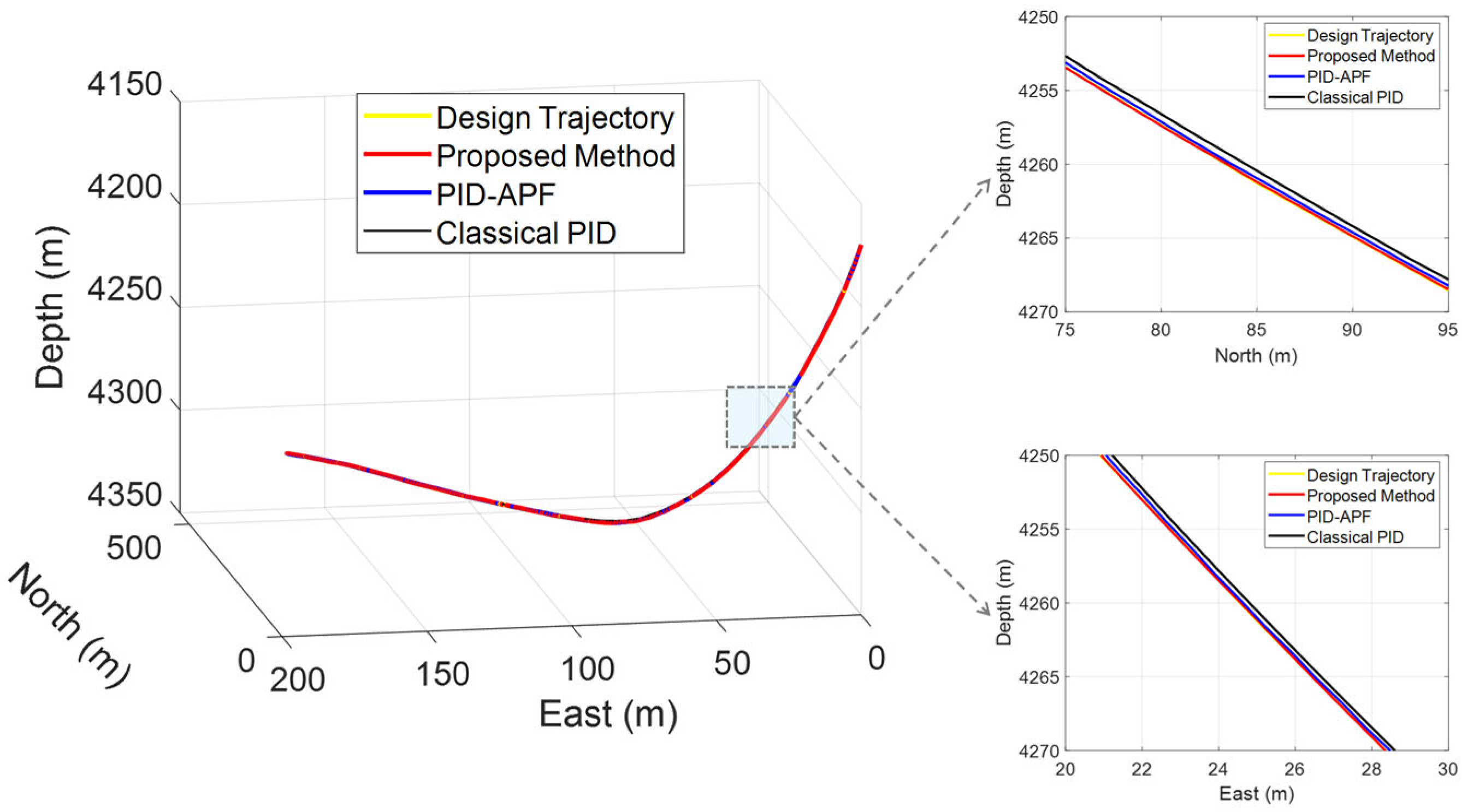
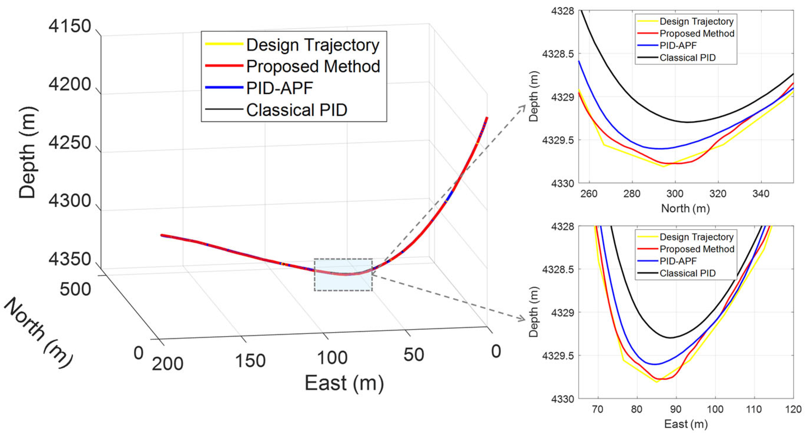
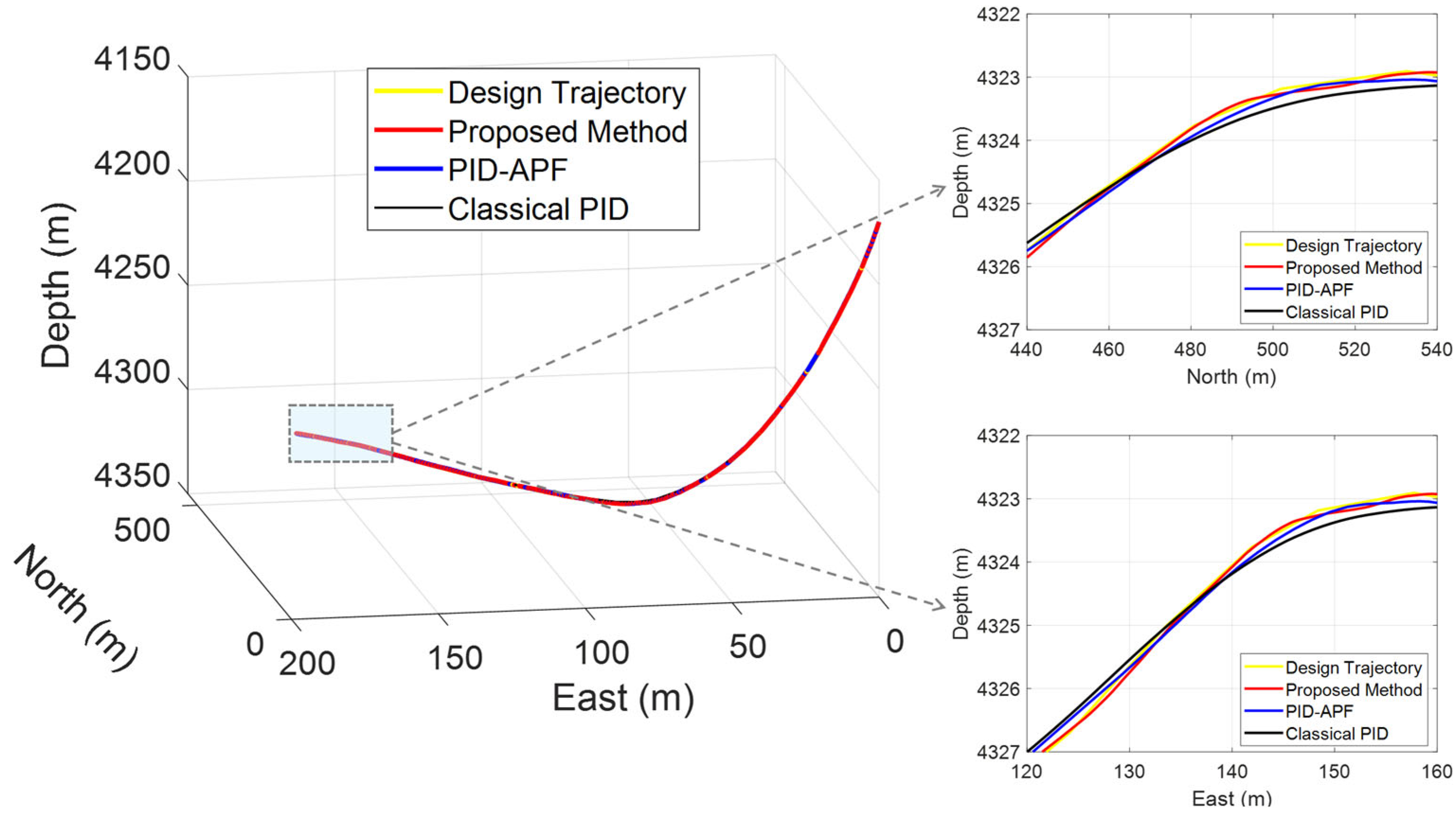
To provide a more intuitive demonstration of the control accuracy, Figure 4, Figure 5 and Figure 6 illustrate three representative local regions for comparative analysis. In each figure, the left panel displays the spatial differences in a three-dimensional view, while the right panels project the trajectories onto the North-Depth and East-Depth planes, respectively, to magnify local deviations. This visualization clearly highlights the extent to which the three methods deviate from the designed trajectory.
Figure 4.
Trajectory comparison of different control methods in the depth interval [4255 m, 4275 m].
Figure 5.
Trajectory comparison of different control methods in the depth interval [4327 m, 4330 m].
Figure 6.
Trajectory comparison of different control methods in the depth interval [4322 m, 4326 m].
Figure 4 illustrates the spatial comparison between the actual trajectories generated by the three control methods and the designed trajectory within the depth interval of [4255 m, 4275 m]. The results show that the trajectories produced by the proposed method and the classical PID method are highly consistent with the designed trajectory, exhibiting almost no noticeable deviation. This can be attributed to the relatively smooth variation in the designed trajectory in this interval. In contrast, the trajectory generated by the PID-APF method shows significant deviation from the designed trajectory. The underlying reason is that the PID-APF approach adjusts PID parameters using the artificial potential field, in which virtual “attractive” and “repulsive” forces are introduced to guide the trajectory toward the target. However, this mechanism is prone to the formation of local equilibrium points, preventing the trajectory from fully coinciding with the designed trajectory.
Figure 5 and Figure 6 present the spatial comparisons between the actual trajectories generated by the three control methods and the designed trajectory within the TVD intervals of [4327 m, 4330 m] and [4322 m, 4326 m], respectively, where the designed trajectory exhibits pronounced turning features. From both the North-TVD and East-TVD perspectives, it can be observed that although the trajectory produced by the proposed method shows slight deviations in the turning region, the overall deviation magnitude is significantly smaller than that of the other two methods. This indicates that the proposed method maintains robust tracking performance even in complex transition segments. In contrast, both the classical PID and PID-APF methods deviate considerably from the designed trajectory. The underlying reason is that the proposed method leverages a genetic algorithm to dynamically adjust the PID parameters, thereby enabling timely correction of trajectory direction. By comparison, the classical PID method employs fixed parameters, making it difficult to cope with sudden curvature changes, while the PID-APF method relies on the potential field model, which lacks adaptability in handling complex designed trajectories.
4.2. Analysis of Steering Tool Force and Tool Face Angle
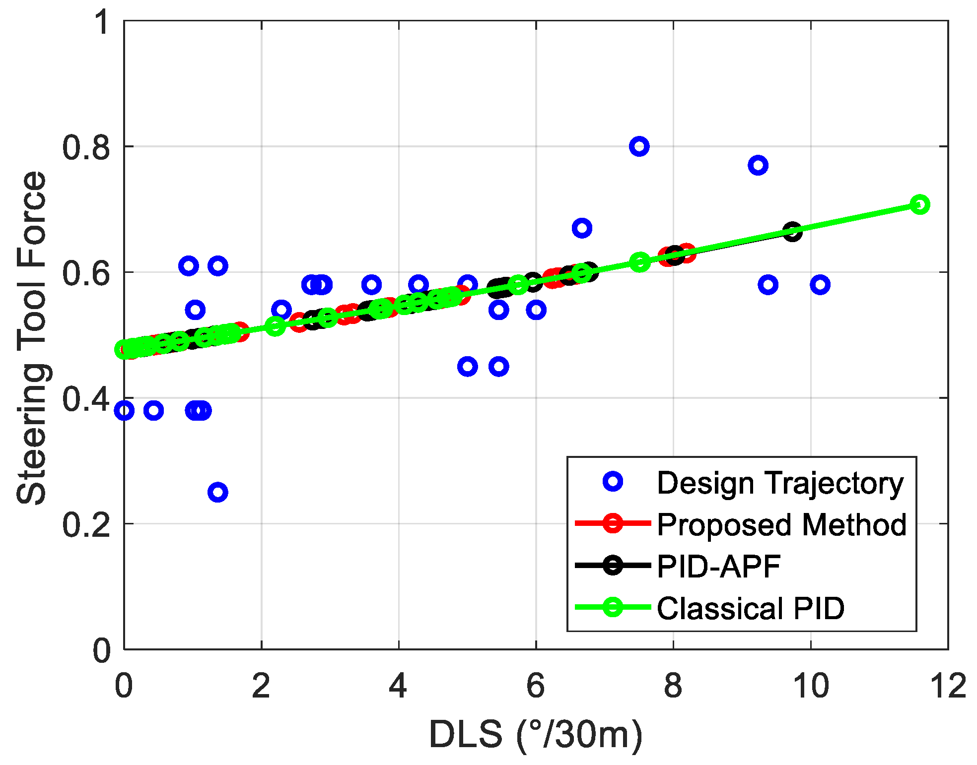
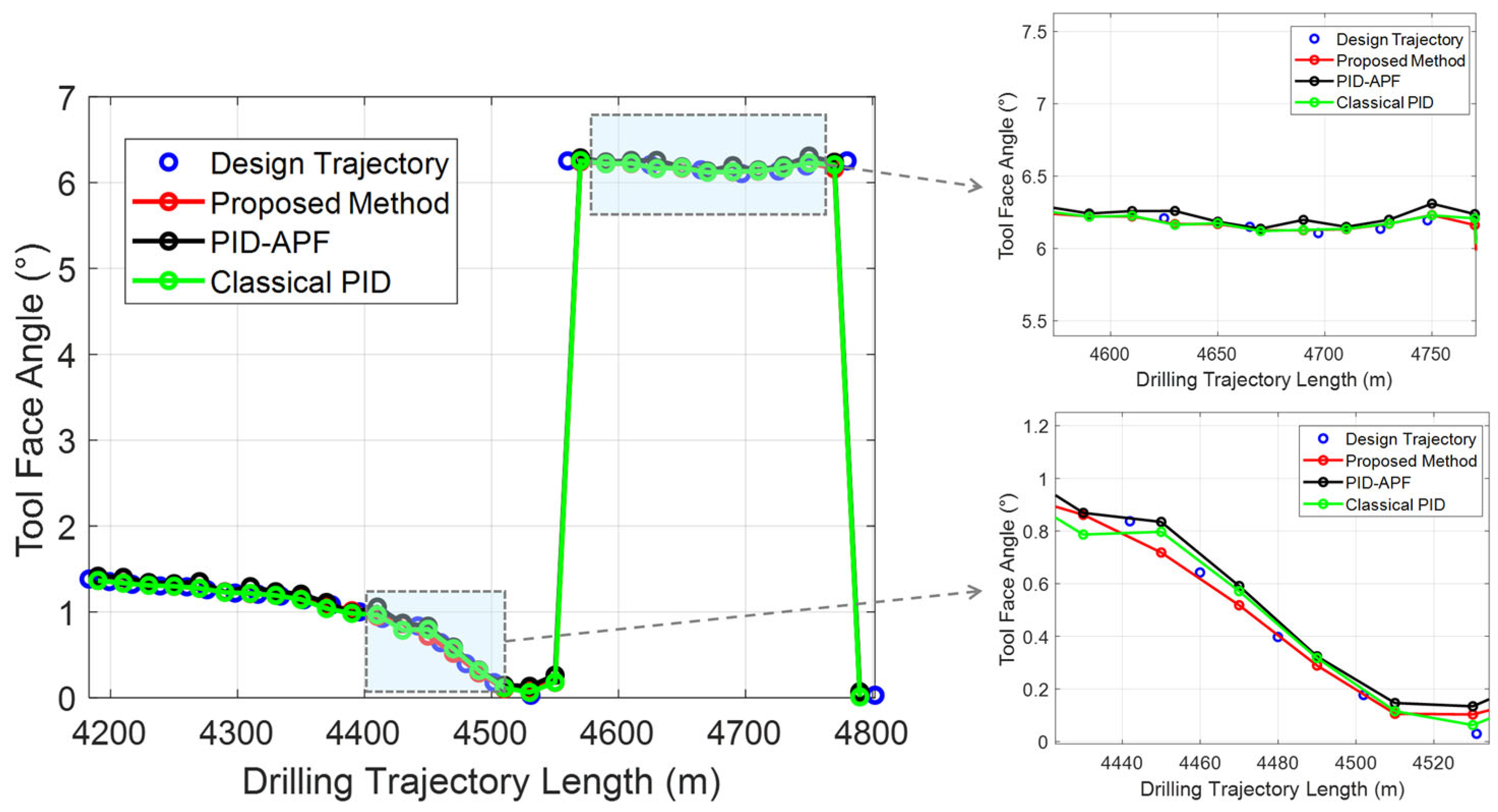
Figure 7 illustrates the relationship between DLS and steering tool force for the three control methods. The results indicate that the steering tool force of the proposed method are largely concentrated within the dense region of the designed trajectory, demonstrating strong consistency. In contrast, portions of the steering tool force generated by the two comparative methods deviate significantly from this region. This finding highlights the superior capability of the proposed method to maintain trajectory smoothness and reasonable control input, thereby achieving improved trajectory-tracking performance under complex conditions. In addition, Figure 8 presents the comparative results of tool face angle variations under different drilling depths for the three control methods. It can be observed that the tool face angle curve generated by the proposed method aligns closely with the designed trajectory across all depths, with the agreement being more evident in the enlarged subfigures on the right. This demonstrates the high attitude-control accuracy achieved by the proposed method.
Figure 7.
The relationship between DLS and steering tool force for three methods.
Figure 8.
Comparison of tool face angle at different well lengths using various control methods.
4.3. Comparison of Normal Distance and Dogleg Severity
Figure 9 provides a clear illustration of the differences in normal distance among the three control methods under varying true vertical depths. It can be observed that, compared with the two benchmark methods, the proposed approach consistently achieves smaller normal distances across most depth intervals. Although slight fluctuations are present in certain segments, the overall deviation remains within 0.15 m. As further confirmed by the statistical results in Table 4, the proposed method yields an average normal distance of only 0.1534 m throughout the entire drilling process, which is significantly lower than those of the classical PID and PID-APF methods, with accuracy improvements of 88.89% and 34.02%, respectively.
Figure 9.
Comparison of normal distance results between three methods at different depths.
Table 4.
Comparison of normal distance and dogleg severity between three methods.
This superior performance can be attributed to the online optimization mechanism introduced in this study, in which a genetic algorithm is adaptively triggered by trajectory deviation. By dynamically adjusting the PID parameters in response to real-time deviations, this mechanism enhances both responsiveness and correction capability when sudden trajectory changes occur. In contrast, the classical PID method relies on fixed control parameters, making it unable to adapt to abrupt variations in trajectory curvature, thereby leading to larger deviations in complex intervals. Although the PID-APF method incorporates adaptive parameter adjustment through the artificial potential field, the potential field model tends to form local equilibrium states in complex wellbore geometries, resulting in insufficient correction or even further deviation from the designed trajectory.
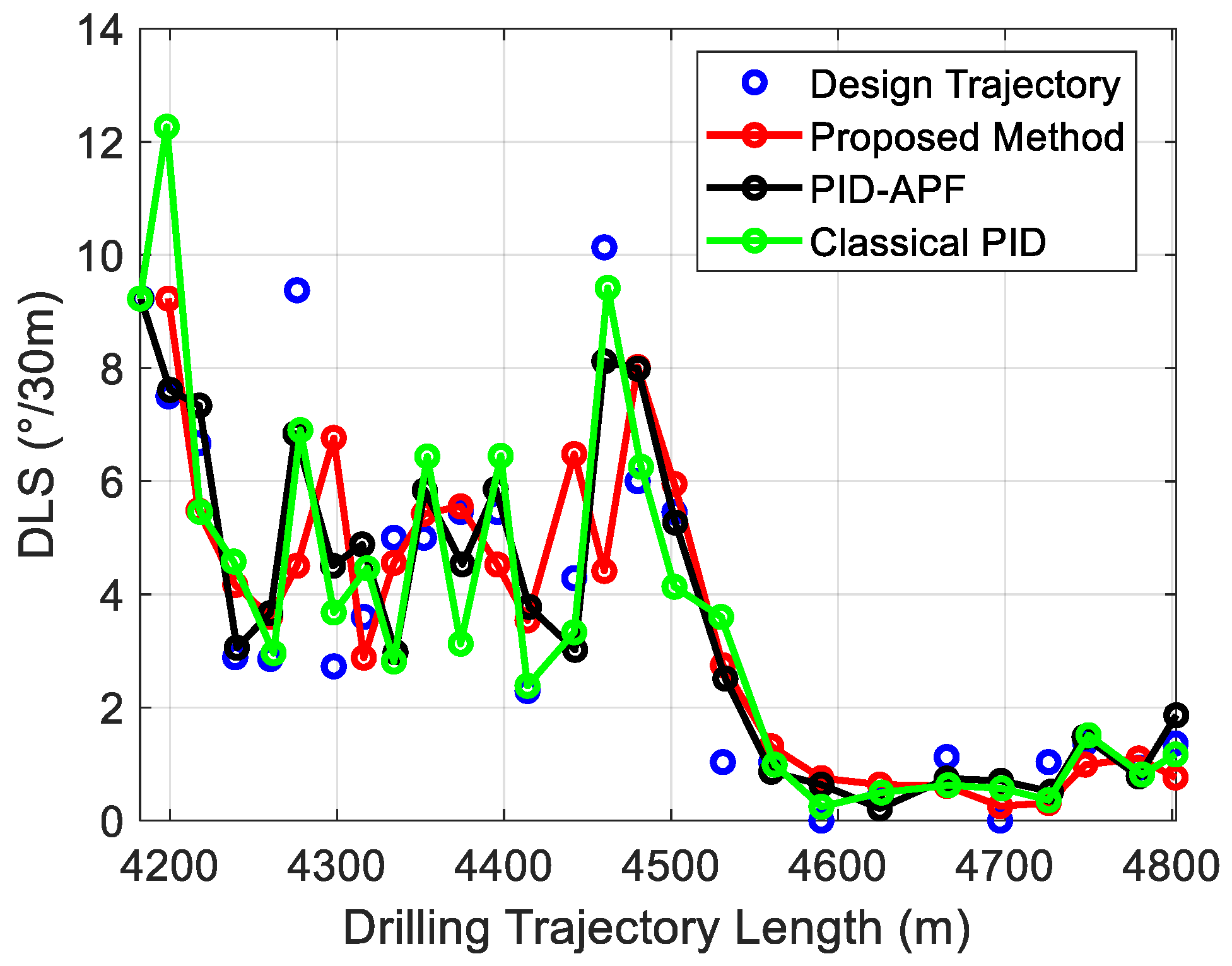
In addition, Figure 10 illustrates the distribution of DLS for the designed trajectory, the proposed method, and the two comparative methods under different drilling lengths. From the overall trend, the DLS curve generated by the proposed method is smoother, with smaller fluctuations, thereby demonstrating stronger trajectory-fitting capability and attitude-control stability. According to the statistical results in Table 4, the average DLS of the proposed method throughout the drilling process is 3.6378 (°/30 m), which is significantly lower than those of the classical PID and PID-APF methods, with reductions of 6.30% and 5.81%, respectively. These findings further confirm the superiority of the proposed method in maintaining attitude stability and controlling trajectory smoothness.
Figure 10.
Comparison of dogleg severity at different well lengths using various control methods.
4.4. Robustness Tests
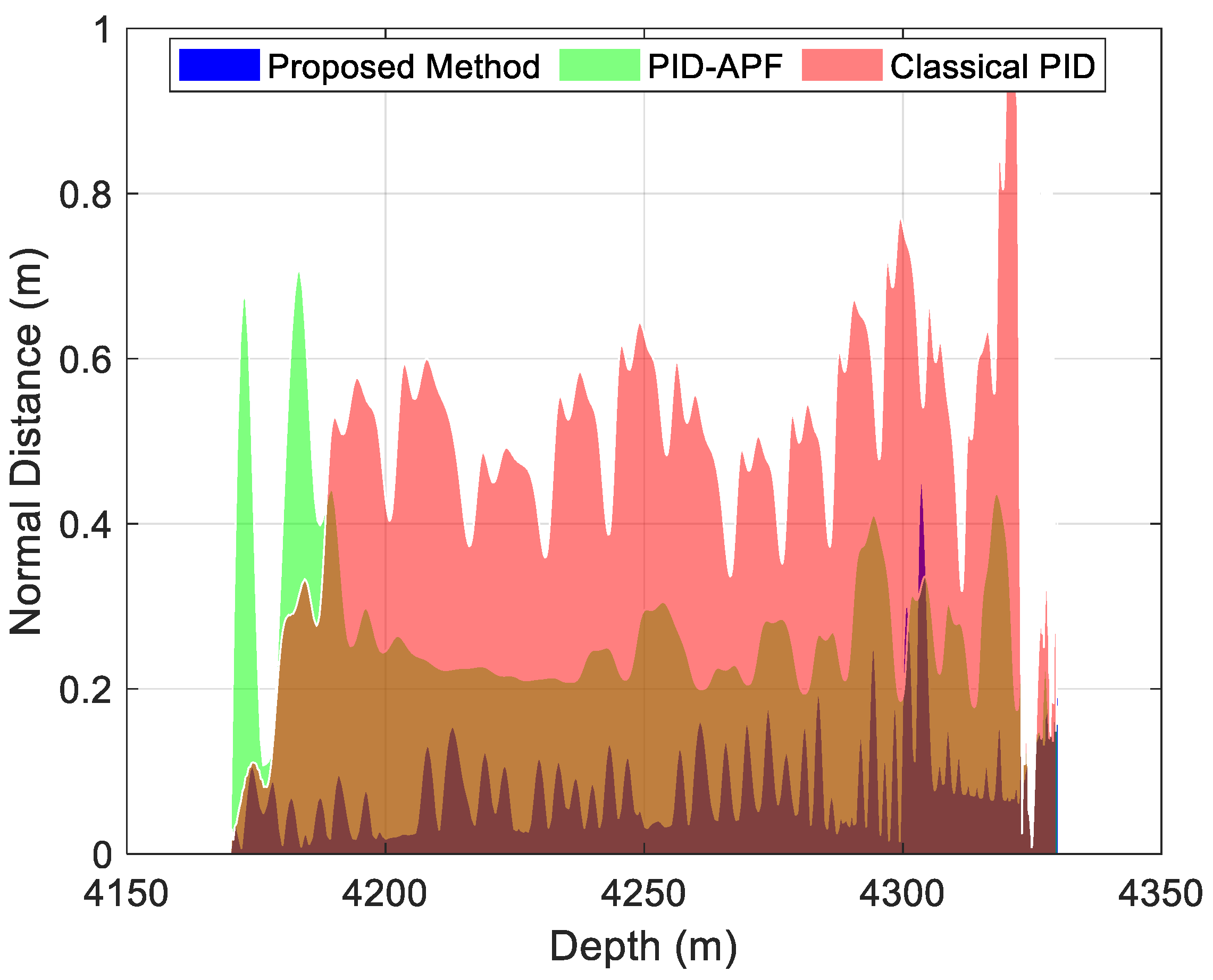
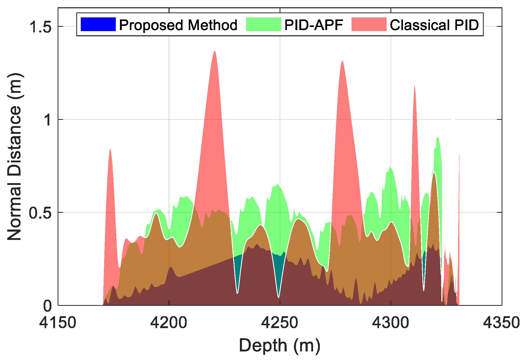
Figure 11 provides a detailed comparison of the normal distance at different drilling depths for the three control methods, considering the impact of noise. Specifically, under the influence of noise, the traditional PID control method results in a larger normal distance between the drilling trajectory and the preset trajectory, as shown in the red shaded area of Figure 11. This is because the traditional PID control method fails to dynamically adapt to fluctuations in measurement noise, leading to delayed control responses and increased trajectory deviations. Under noise interference, although the PID-APF method adjusts PID parameters using the artificial potential field strategy, it cannot effectively and timely correct the PID parameters due to the inherent limitations of the artificial potential field itself. As a result, in some depth intervals, the normal distance between the drilling trajectory and the preset trajectory still exceeds the predefined threshold, as shown in the green shaded area of Figure 11. In contrast, the proposed method dynamically optimizes PID parameters by combining a GA, enabling real-time responses to noise effects. When the normal distance between the drilling trajectory and the preset trajectory exceeds the set threshold, the proposed method immediately triggers PID parameter optimization to quickly correct the deviation. Therefore, under the influence of noise, the normal distance between the drilling trajectory and the preset trajectory remains within the set threshold throughout, as shown in the blue shaded area of Figure 11, demonstrating higher accuracy and stability.
Figure 11.
Normal distance at different depths for three control methods under noise impact.
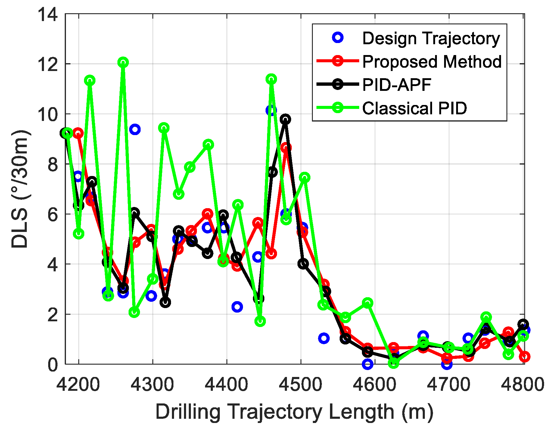
Figure 12 shows the comparison of DLS at different trajectory lengths for three control methods, considering the impact of noise. From the comparison results, it is evident that the traditional PID control method exhibits higher and more fluctuating DLS under noise interference, demonstrating poor trajectory smoothness. This is because the traditional PID method fails to effectively adapt to noise and trajectory changes, leading to delayed control responses and increased fluctuations in DLS. However, both the PID-APF and the proposed method, through adaptive PID parameter adjustment mechanisms, can effectively reduce the fluctuations in DLS, keeping the values lower and more stable. Specifically, the proposed method, by introducing a GA to dynamically optimize PID parameters, further improves control performance under noise influence, resulting in a smaller dogleg severity compared to PID-APF. This advantage is validated in Table 5. Specifically, Table 5 shows that, throughout the drilling process, the average DLS for the three methods (proposed method, traditional PID control, and PID-APF) are 3.6339°/30 m, 4.7425°/30 m, and 3.8191°/30 m, respectively. These data show that the proposed method performs best in reducing DLS, confirming the effectiveness of the GA in optimizing PID parameters. Additionally, Table 5 also presents the average normal distance for all three methods throughout the drilling process. The comparison results show that the proposed method also has a significant advantage in controlling the normal distance.
Figure 12.
Comparison of DLS at different lengths for three control methods under noise impact.
Table 5.
Comparison of normal distance and DLS among three methods under noise impact.
5. Discussion
The intelligent steering method proposed in this study demonstrates significant advantages in trajectory-tracking accuracy and attitude-control stability. In particular, during actual drilling operations, when the trajectory deviates from the designed path, the method can automatically adjust PID parameters through an adaptive online optimization mechanism, thereby redirecting the drilling direction back toward the planned trajectory and effectively suppressing the accumulation and amplification of deviations. Compared with traditional PID methods, the proposed approach not only shows superior performance in controlling normal distance and dogleg severity but also achieves a smoother trajectory control process.
From the perspective of engineering applications, this method can output the tool face angle and steering tool force in real-time, providing field engineers with more intuitive and reliable decision-making references. This not only helps with more rational drilling planning but also improves the automation level of wellbore trajectory control, reducing the need for manual intervention. The deep integration of control and information output is reflected in the following aspects: first, the real-time output of tool face angle and control force allows engineers to promptly obtain real-time information during the drilling process, enabling better adjustments to the drilling direction. Second, the increased level of automation reduces human operation errors and enhances the stability and efficiency of the control system.
Although the method proposed in this study performs excellently in wellbore trajectory control, it still has certain limitations. Due to practical limitations, this study is primarily validated based on drilling data from a single well in the Luzhou block, which is located in the Longmaxi Formation. The formation mainly consists of mudstone, silty mudstone, and shale. Additionally, the preset trajectory shape includes vertical, build-up, and holding sections. Due to the limited dataset, the validation results are mainly applicable to cases with similar lithology and trajectory shapes. Further research will be carried out with more drilling and formation data available.
6. Conclusions
This paper addresses the issues of error accumulation, response delay, and control instability in traditional PID control methods for intelligent directional drilling. To address these issues, this paper proposes an intelligent closed-loop steering method based on online adaptive optimization. By incorporating a GA for real-time PID optimization, along with an attitude error feedback mechanism and control output model, the method improves trajectory tracking accuracy and suppresses wellbore curvature fluctuations, reducing trajectory deviation risk. The main conclusions of this study are as follows:
- (1)
- The proposed method possesses adaptive adjustment capability, enabling real-time response to posture disturbances and thereby enhancing system stability and control accuracy. Compared to the traditional PID and PID-APF methods, the normal distance accuracy improves by 88.89% and 34.02%, respectively, under noise-free conditions; under noise interference, the accuracy improves by 56.73% and 54.97%, respectively.
- (2)
- The proposed method significantly reduces DLS during the drilling process, resulting in a smoother trajectory. Compared to the traditional PID and PID-APF methods, the DLS decreases by 6.30% and 5.81%, respectively, under noise-free conditions; under noise interference, the DLS decreases by 23.38% and 4.85%, respectively.
- (3)
- A control output model based on posture data has been established, which can accurately predict the required force and tool face angle for the steering tool. This enhances the real-time and practical aspects of control quantity calculations, facilitating field guidance and the deployment of automation control systems.
Future research will extend to different types of geological formations and trajectory shapes, developing an “engineering–geology” coupled intelligent steering model to enhance the adaptability of this method in complex geological environments. In addition, we plan to integrate reinforcement learning with real-time logging data to further improve the self-learning capability of the control strategy, enabling it to better handle the changing underground environment and enhance the system’s adaptability and robustness under varying operational conditions.
Author Contributions
Conceptualization, Y.S. and D.C.; methodology, Z.W.; software, Z.W.; validation, D.C. and Z.W.; formal analysis, Z.W. and Y.F.; investigation, K.S. and Y.F.; resources, Y.S., K.S. and Y.F.; data curation, K.S. and Y.F.; writing—original draft preparation, Z.W.; writing—review and editing, Y.S. and D.C.; visualization, Y.F.; supervision, Y.S. and K.S.; project administration, Y.S., K.S., Y.F. and D.C.; funding acquisition, Y.S. and D.C. All authors have read and agreed to the published version of the manuscript.
Funding
This research was supported in part by the scientific research and technology development projects of China National Petroleum Corporation Oilfield Technology Service Company Limited (grant number 2024T-001-001), the Oil & Gas Major Project (Grant No. 2025ZD1404600), and the National Natural Science Foundation of China (grant number 52394250).
Data Availability Statement
Data are contained within this article.
Conflicts of Interest
Authors Yan Sun, Kun Shao and Yongtao Fan were employed by the company China National Logging Corporation. The remaining authors declare that the research was conducted in the absence of any commercial or financial relationships that could be construed as a potential conflict of interest.
Abbreviations
The following abbreviations are used in this manuscript:
| AA | Azimuth angle |
| DLS | Dogleg severity |
| GA | Genetic algorithm |
| IA | Inclination angle |
| STD | Standard deviation |
| PID | Proportional-integral-derivative |
| PID-APF | PID method based on the artificial potential field |
Appendix A
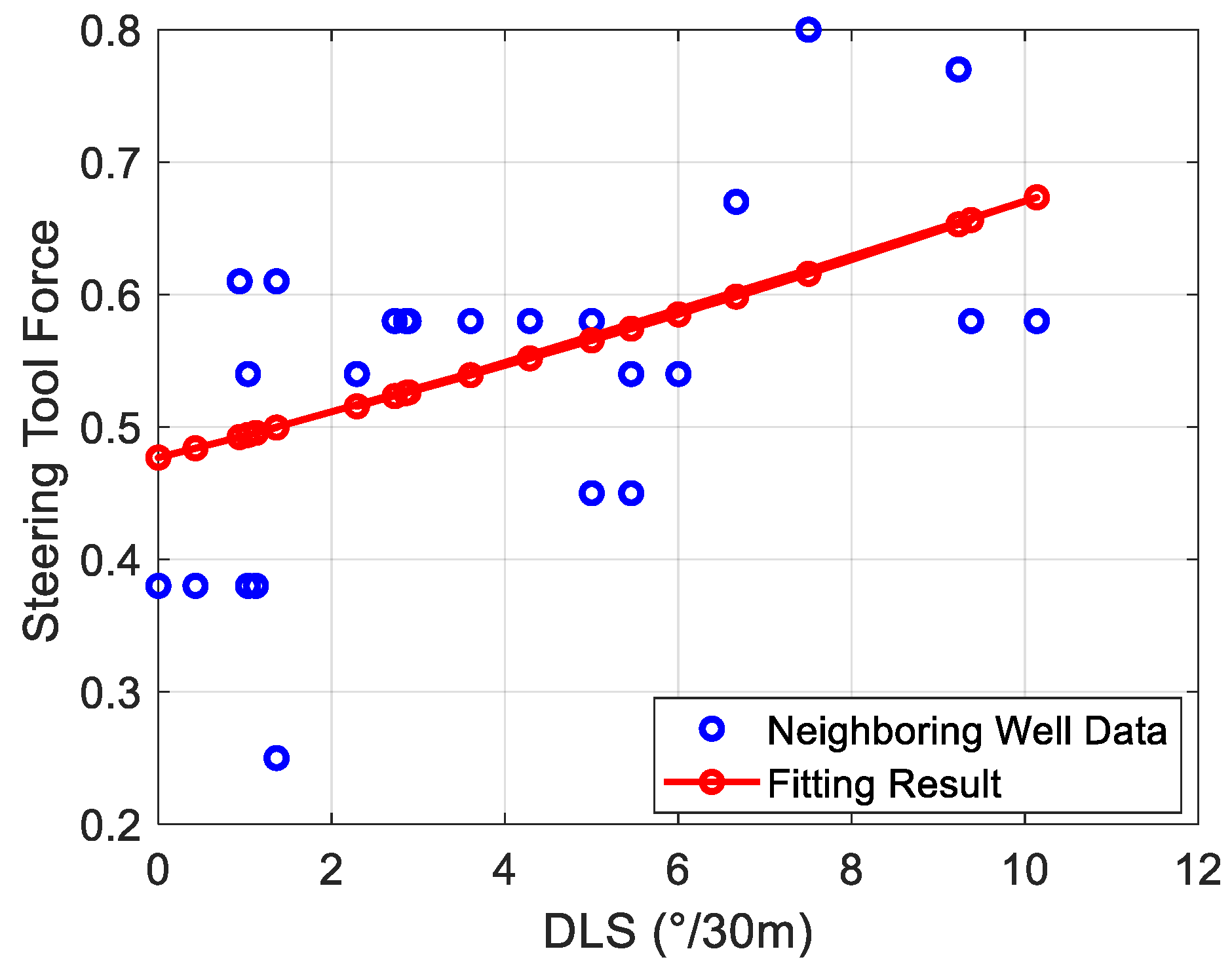
In this study, the mapping function between steering tool force and DLS is fitted based on neighboring well data. The neighboring well data comes from one actual trajectory in the Luzhou block and its corresponding steering tool force data, with a total of 27 data pairs, as shown in Table A1. To capture the nonlinear relationship between DLS and steering tool force, an exponential regression model is used for fitting. The resulting mathematical expression is shown in Equation (A1), with a coefficient of determination of 0.30 and a mean square error of 0.0102.
where represents the steering tool force, and represents the DLS. Although the fitting accuracy is relatively limited, the function effectively reflects the overall trend of the relationship between DLS and steering tool force (as shown in Figure A1), providing a reference for subsequent control strategies.
Table A1.
Neighboring well data and corresponding steering tool force data from the Luzhou block.
Table A1.
Neighboring well data and corresponding steering tool force data from the Luzhou block.
| Starting Depth (m) | End Depth (m) | Drilled Footage (m) | SIA (°) | SAA (°) | DLS (°/30 m) | STF |
|---|---|---|---|---|---|---|
| 4170 | 4183 | 13 | 31 | 17 | 9.02 | 67% |
| 4183 | 4199 | 16 | 35 | 17 | 9.23 | 77% |
| 4199 | 4217 | 18 | 39 | 17 | 7.50 | 80% |
| 4217 | 4239 | 22 | 43 | 17 | 6.66 | 67% |
| 4239 | 4260 | 21 | 45 | 16 | 2.88 | 58% |
| 4260 | 4276 | 16 | 47 | 16 | 2.85 | 58% |
| 4276 | 4298 | 22 | 52 | 16 | 9.37 | 58% |
| 4298 | 4316 | 18 | 54 | 16 | 2.72 | 58% |
| 4316 | 4334 | 18 | 56 | 15 | 3.60 | 58% |
| 4334 | 4352 | 18 | 59 | 15 | 5.00 | 58% |
| 4352 | 4374 | 22 | 62 | 15 | 5.01 | 45% |
| 4374 | 4396 | 22 | 66 | 15 | 5.45 | 45% |
| 4396 | 4414 | 18 | 70 | 15 | 5.46 | 45% |
| 4414 | 4442 | 28 | 71 | 16 | 2.29 | 54% |
| 4442 | 4460 | 18 | 75 | 16 | 4.28 | 58% |
| 4460 | 4480 | 20 | 81 | 17 | 10.13 | 58% |
| 4480 | 4502 | 22 | 85 | 17 | 6.00 | 54% |
| 4502 | 4531 | 29 | 89 | 17 | 5.45 | 54% |
| 4531 | 4560 | 29 | 90 | 17 | 1.03 | 54% |
| 4560 | 4590 | 30 | 91 | 17 | 1.03 | 54% |
| 4590 | 4625 | 35 | 91 | 17 | 0.68 | 38% |
| 4625 | 4665 | 40 | 91.5 | 17 | 0.42 | 38% |
| 4665 | 4697 | 32 | 93 | 17 | 1.12 | 38% |
| 4697 | 4726 | 29 | 93 | 17 | 0.21 | 38% |
| 4726 | 4748 | 22 | 92 | 17 | 1.03 | 38% |
| 4748 | 4780 | 32 | 91 | 17 | 1.36 | 61% |
| 4780 | 4802 | 22 | 90 | 17 | 0.93 | 61% |
| 4802 | 4835 | 33 | 89 | 17 | 1.36 | 25% |
Note: SIA, SAA and STF are abbreviations for starting inclination angle, starting azimuth angle and steering tool force, respectively.
Figure A1.
Fitting curve of steering tool force versus dogleg severity based on neighboring well data.
Appendix B
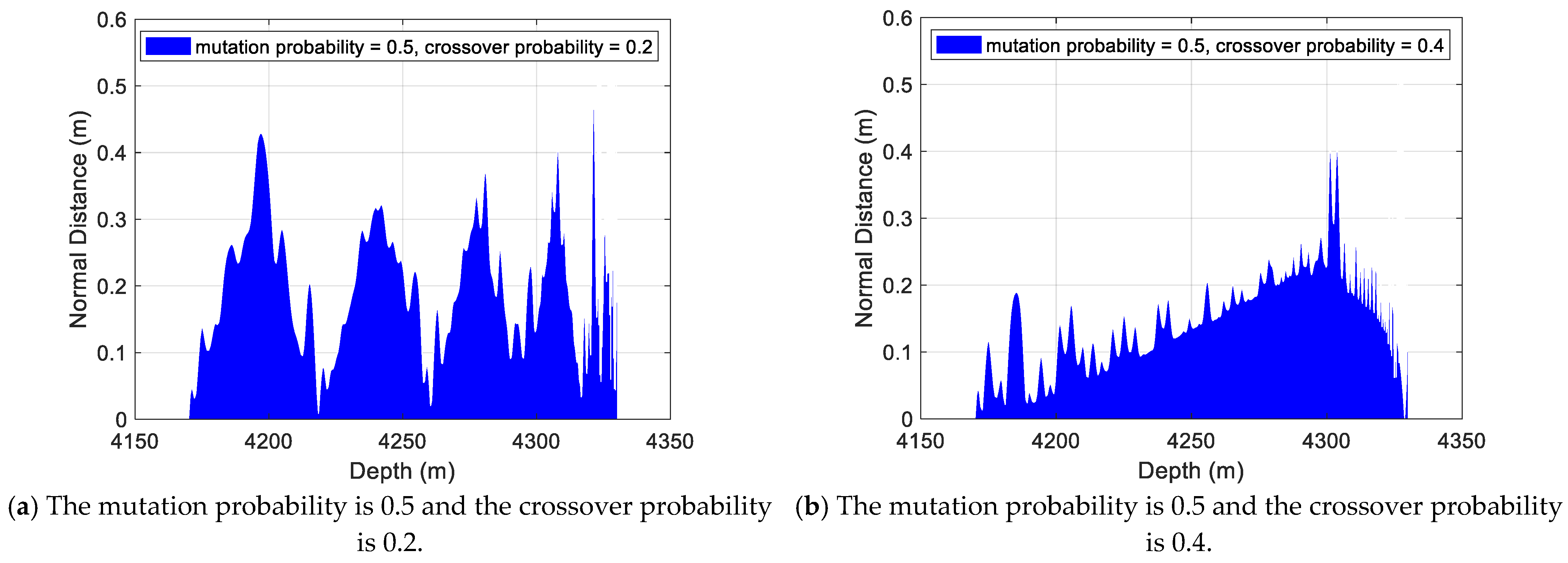
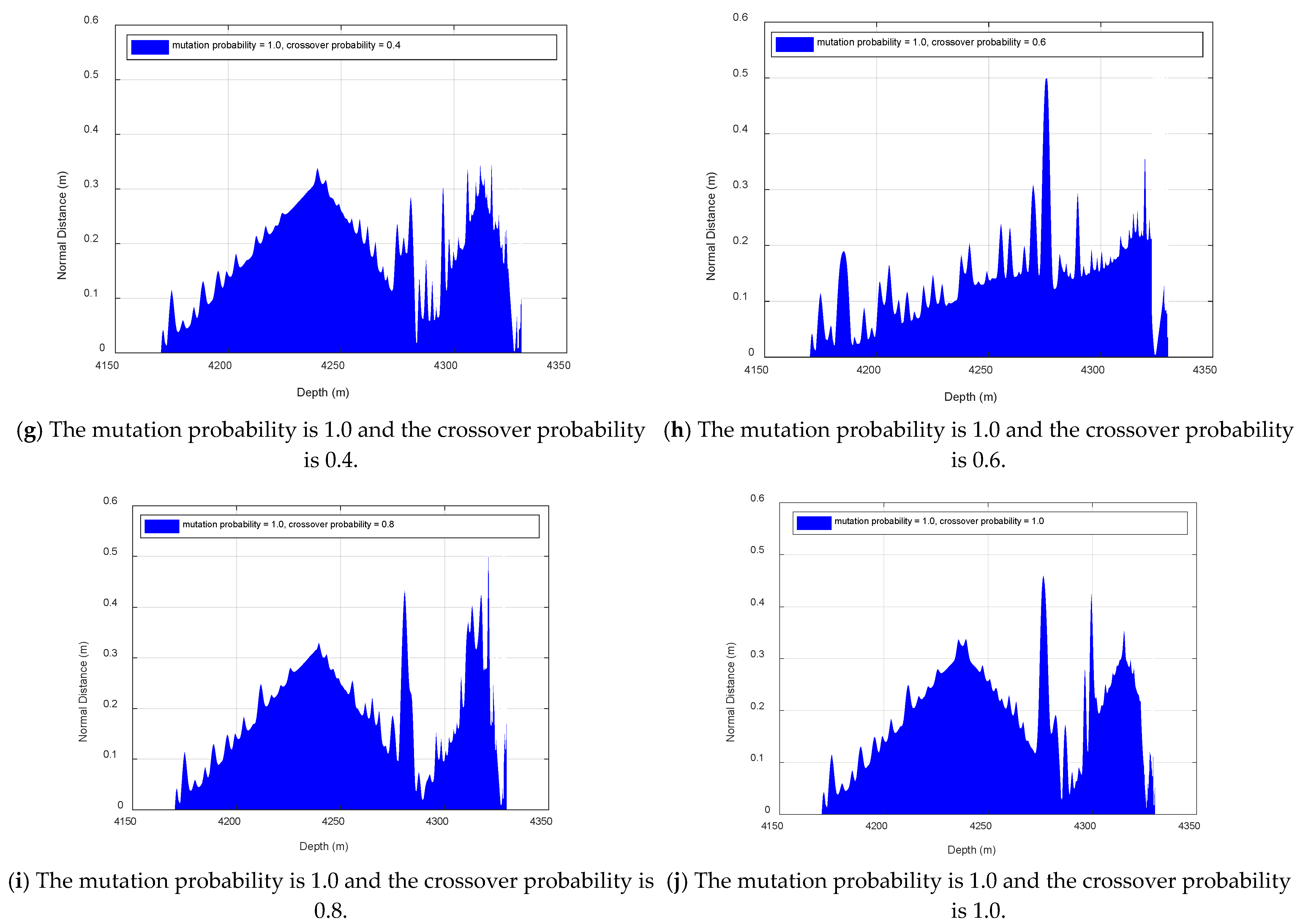
In this study, the main objective of the genetic algorithm is not to strictly find the globally optimal PID parameters, but to obtain a feasible solution through a global search mechanism that effectively constrains the drilling trajectory deviation, keeping the normal distance between the drilling trajectory and the preset trajectory within a specified threshold. To verify the sensitivity of the algorithm’s results to parameter settings, a parameter sensitivity analysis is conducted. Specifically, the mutation probability is set to 0.5 and 1.0, and the crossover probability is set to 0.2, 0.4, 0.6, 0.8, and 1.0, forming a total of 10 different parameter combinations. For each combination, we calculate the normal distance between the wellbore trajectory and the preset trajectory (see Figure A2), with the maximum allowable normal distance set to 0.5 m. The analysis results show that for all parameter combinations, the normal distance at different depths during the drilling process is always less than the set threshold.


Figure A2.
Distribution of normal distance during drilling under different parameter combinations.
In addition, Table A2 shows the mean and variance of the normal distance throughout the drilling process under different parameter combinations. When the crossover probability and mutation probability are set to 0.5 and 0.8, respectively, the average normal distance and standard deviation throughout the drilling process are 0.171 m and 0.07 m, which represent the optimal results among all parameter combinations. Therefore, in the subsequent PID parameter optimization, we fix the crossover probability and mutation probability at 0.5 and 0.8, respectively.
Table A2.
Mean and STD of normal distance during drilling under different parameter combinations.
Table A2.
Mean and STD of normal distance during drilling under different parameter combinations.
| Parameter Combination | Mean | STD | Parameter Combination | Mean | STD |
|---|---|---|---|---|---|
| CR = 0.2, MU = 0.5 | 0.391 | 0.450 | CR = 0.2, MU = 1.0 | 0.209 | 0.121 |
| CR = 0.4, MU = 0.5 | 0.172 | 0.147 | CR = 0.4, MU = 1.0 | 0.185 | 0.085 |
| CR = 0.6, MU = 0.5 | 0.349 | 0.569 | CR = 0.6, MU = 1.0 | 0.172 | 0.139 |
| CR = 0.8, MU = 0.5 | 0.171 | 0.070 | CR = 0.8, MU = 1.0 | 0.205 | 0.110 |
| CR = 1.0, MU = 0.5 | 0.176 | 0.082 | CR = 1.0, MU = 1.0 | 0.196 | 0.087 |
Note: STD, CR and MU are abbreviations for standard deviation, crossover probability and mutation probability, respectively.
Appendix C
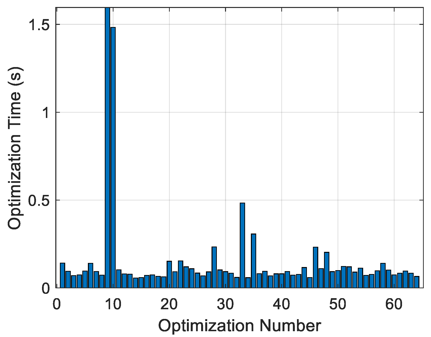
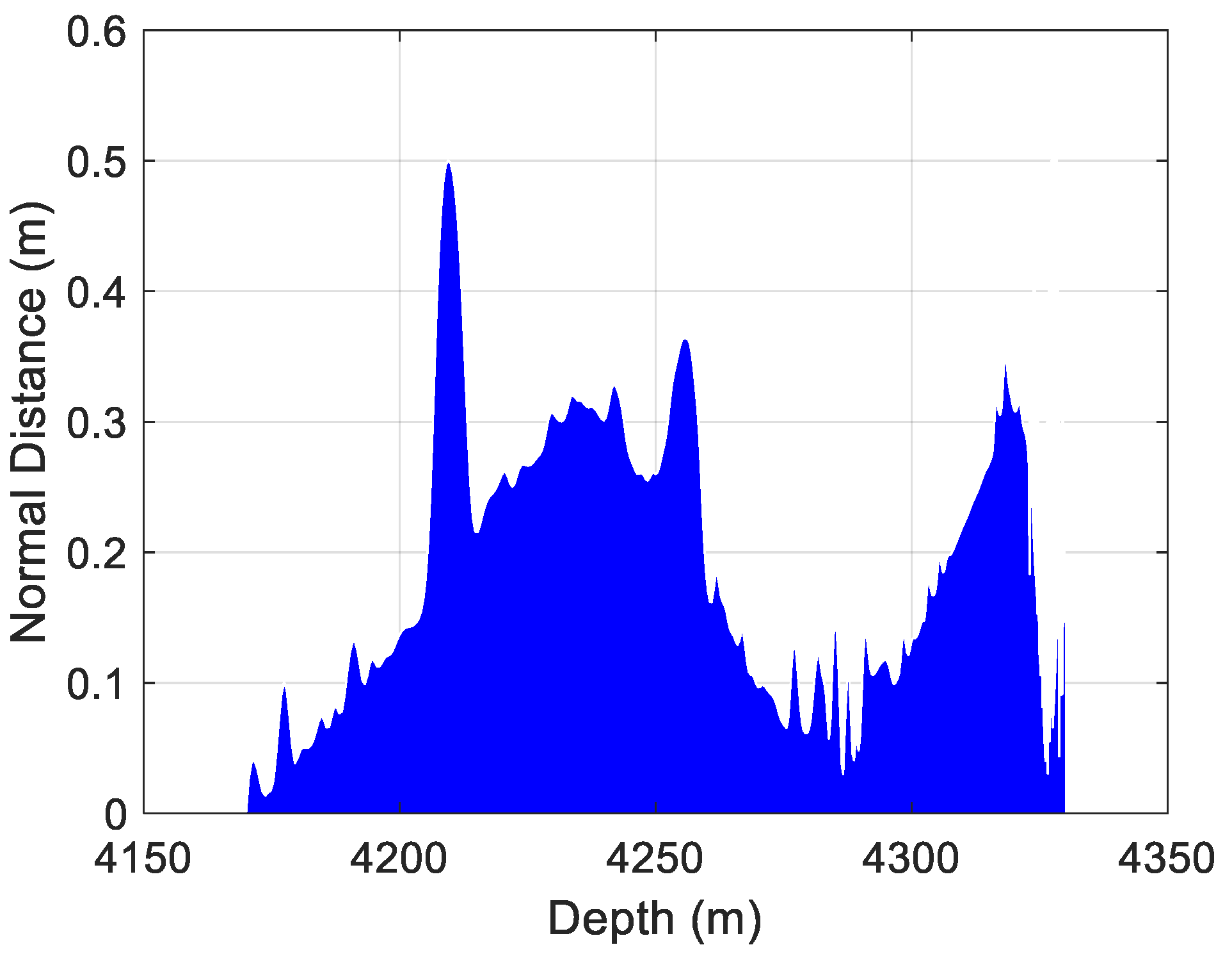
To verify the computational efficiency of GA-optimized PID parameters, Figure A3 shows the distribution of computation time for each PID parameter optimization throughout the entire drilling process. Figure A4 shows the distribution of normal distance between the drilling trajectory and the preset trajectory in the drilling process. As shown in Figure A4, the normal distance between the drilling trajectory and the preset trajectory remains below the threshold (set to 0.5 m) throughout the drilling process, meeting the trajectory control accuracy requirements. Based on this, Figure A3 indicates that only two optimization times exceed 1 s during the drilling process, which occurred when the direction difference between the drilling trajectory and the preset trajectory was large, requiring more iterations to meet the needs. Apart from these two instances, the remaining optimization times are all below 0.2 s. The statistical results show that the average optimization time is approximately 0.15 s, indicating that the GA optimization process for PID parameters completes parameter updates within an acceptable time frame, demonstrating good real-time performance and responsiveness.
Figure A3.
Computation time of each GA optimization for PID parameters in the drilling process.
Figure A4.
Normal distance at different depths.
References
- Liu, X.; Jiang, Z.; Wang, Y.; Mo, H.; Li, H.; Guo, J. Research on trajectory control technology for L-shaped horizontal exploration wells in coalbed methane. Sci. Rep. 2024, 14, 11343. [Google Scholar] [CrossRef]
- Zhang, N.; Li, F.; Ren, B.; Liu, Z.; Wang, D.; Chen, J.; Lyu, F. Research on Wellbore Trajectory Control of Rotary Steerable System Using Back-Propagation Neural Network-Fuzzy Method. Geoenergy Sci. Eng. 2025, 257, 214201. [Google Scholar] [CrossRef]
- Gu, H.; Wu, Y.; Li, X.; Hou, Z. Research on Wellbore Trajectory Optimization and Drilling Control Based on the TD3 Algorithm. Appl. Sci. 2025, 15, 7258. [Google Scholar] [CrossRef]
- Li, Z.; Song, X.; Yan, B.; Zhu, Z.; Zhang, C.; Tian, L.; Yu, Q. Fine-Tuning Wellbore Trajectory in Rotary Drilling Using Machine Learning–Based Model Predictive Control. SPE J. 2025, 1–19. [Google Scholar] [CrossRef]
- Chen, S.; Hu, G.; Huang, X.; Zhang, G.; Liu, X. Influence of wellbore dogleg severity on drilling friction in horizontal wells. Geofluids 2023, 2023, 9973863. [Google Scholar]
- Dunn, J. Identifying cumulative TVD error in horizontal wells drilled with rotary steerable systems. In Proceedings of the SPE/IADC Drilling Conference and Exhibition, Galveston, TX, USA, 5–7 March 2024. [Google Scholar]
- Zafarian, H.; Ameri, M.; Vaghasloo, Y.A. Error reduction of tracking planned trajectory in a thin oil layer drilling using smart rotary steerable system. J. Pet. Sci. Eng. 2021, 196, 107668. [Google Scholar] [CrossRef]
- Eltayeb, A.; Ahmed, G.; Imran, I.H.; Alyazidi, N.M.; Abubaker, A. Comparative analysis: Fractional PID vs. PID controllers for robotic arm using genetic algorithm optimization. Automation 2024, 5, 230–245. [Google Scholar] [CrossRef]
- Karam, E.H.; Al-Gburi, A.K.; Abd Mohammed, Y. An Adaptive Robust PID Controller Design for a Single Motorized Robotic Arm. J. Eng. Sustain. Dev. 2025, 29, 682–690. [Google Scholar] [CrossRef]
- Admas, Y.A.; Mitiku, H.M.; Salau, A.O.; Omeje, C.O.; Braide, S.L. Control of a fixed wing unmanned aerial vehicle using a higher-order sliding mode controller and non-linear PID controller. Sci. Rep. 2024, 14, 23139. [Google Scholar] [CrossRef] [PubMed]
- Wang, J.; Liang, S.; Guo, M.; Wang, H.; Zhang, H. Adaptive multimodal control of trans-media vehicle based on deep reinforcement learning. Eng. Appl. Artif. Intell. 2025, 139, 109524. [Google Scholar] [CrossRef]
- Amertet, S.; Gebresenbet, G.; Alwan, H.M. Modeling of unmanned aerial vehicles for smart agriculture systems using hybrid fuzzy PID controllers. Appl. Sci. 2024, 14, 3458. [Google Scholar] [CrossRef]
- Boonkirdram, S.; Audomsi, S.; Sa-Ngiamvibool, W.; Kasemsin, W. Design of Two-Degree-of-Freedom PID Controllers Optimized by Bee Algorithm for Frequency Control in Renewable Energy Systems. Energies 2025, 18, 4880. [Google Scholar] [CrossRef]
- Lin, J.; Yuan, W.; Hu, Z.; Huang, Z.; Yan, Z.; Huang, H.; Zheng, R. Fuzzy PID Individual Pitch Control with Effective Wind Speed Estimation for Offshore Floating Wind Turbines. Energies 2025, 18, 4812. [Google Scholar] [CrossRef]
- Inyang, I.J.; Whidborne, J.F. Bilinear modelling, control and stability of directional drilling. Control Eng. Pract. 2019, 82, 161–172. [Google Scholar] [CrossRef]
- Hernandez-Suarez, R.; Puebla, H.; Aguilar-Lopez, R.; Hernandez-Martinez, E. An integral high-order sliding mode control approach for stick-slip suppression in oil drillstrings. Pet. Sci. Technol. 2009, 27, 788–800. [Google Scholar] [CrossRef]
- Alvarado-Silva, C.A.; de Oliveira, G.C.R.; Gamboa, A.A.R.; Gaytan-Reyna, K.L.; Guidi, E.S.; Azevedo Silva, F.; Gamarra-Rosado, V.O. A Simulation Study on Pressure Control in Oil Well Drilling Using Gain-Scheduled PID Controllers. Appl. Sci. 2025, 15, 2748. [Google Scholar] [CrossRef]
- Laib, A.; Talbi, B.; Krama, A.; Gharib, M. Hybrid interval type-2 fuzzy PID+ I controller for a multi-DOF oilwell drill-string system. IEEE Access 2022, 10, 67262–67275. [Google Scholar] [CrossRef]
- Zhang, N.; Li, F.; Liu, Z.; Ren, B.; Chen, J. Inclination-holding Control Method for Rotary Steerable System Based on Fuzzy-PID. In Proceedings of the 2024 6th International Conference on Intelligent Control, Measurement and Signal Processing (ICMSP), Xi’an, China, 29 November–1 December 2024; pp. 31–34. [Google Scholar]
- Fang, C.; Wang, Q.; Jiang, H.; Chen, Z.; Wang, Y.; Zhai, W.; Chen, S. Shale wellbore stability and well trajectory optimization: A case study from Changning, Sichuan, China. Pet. Sci. Technol. 2023, 41, 564–585. [Google Scholar] [CrossRef]
- Isaev, A.A.; Aliev, M.M.O.; Drozdov, A.N.; Gorbyleva, Y.A.; Nurgalieva, K.S. Improving the efficiency of curved wells’ operation by means of progressive cavity pumps. Energies 2022, 15, 4259. [Google Scholar] [CrossRef]
- Hu, Y.; Wang, L.; Li, J.; Weng, H.; Zheng, Z.; Wen, G.; Zhang, F. Predicting the Temperature Rise in Oil-Immersed Transformers Based on the Identification of Thermal Circuit Model Parameters. Energies 2025, 18, 4707. [Google Scholar] [CrossRef]
- Liu, X. Directional deflection equations for steerable drilling tools and the control mechanism of wellbore trajectory. Pet. Explor. Dev. 2017, 44, 834–839. [Google Scholar] [CrossRef]
- Liu, Y.; Zhu, R.; Zhai, S.; Li, N.; Li, C. Lithofacies identification of shale formation based on mineral content regression using LightGBM algorithm: A case study in the Luzhou block, South Sichuan Basin, China. Energy Sci. Eng. 2023, 11, 4256–4272. [Google Scholar] [CrossRef]
- Han, L.; Li, X.; Liu, Z.; Duan, G.; Wan, Y.; Guo, X.; Guo, W.; Cui, Y. Influencing factors and prevention measures of casing deformation in deep shale gas wells in Luzhou block, southern Sichuan Basin, SW China. Pet. Explor. Dev. 2023, 50, 979–988. [Google Scholar] [CrossRef]
- Ji, S.; Zhang, C.; Tian, L.; Ran, L.; Yang, Y. Dead reckoning method for tracking wellbore trajectories constrained by the drill pipe length. IEEE Trans. Instrum. Meas. 2024, 73, 1–12. [Google Scholar] [CrossRef]
Disclaimer/Publisher’s Note: The statements, opinions and data contained in all publications are solely those of the individual author(s) and contributor(s) and not of MDPI and/or the editor(s). MDPI and/or the editor(s) disclaim responsibility for any injury to people or property resulting from any ideas, methods, instructions or products referred to in the content. |
© 2025 by the authors. Licensee MDPI, Basel, Switzerland. This article is an open access article distributed under the terms and conditions of the Creative Commons Attribution (CC BY) license (https://creativecommons.org/licenses/by/4.0/).