Abstract
Existing faulty coal-fired units generally achieve oil-free stable combustion only at loads over 30%, failing to meet low load regulation demands. To address the insufficient flexibility of boilers, a novel flame-stabilization theory was developed for retrofitting a 350 MW faulty coal-fired unit boiler. Based on the actual burner dimensions of the 350 MW unit boiler, a geometric scaling ratio of 1:7 between model and actual burners was established. Phase Doppler Anemometry (PDA) was employed to conduct gas particle flow experiments on the model burner, revealing the impact of different primary air velocities on the gas particle flow characteristics of the novel stabilized flow burner. The analysis of experimental results suggests that, When the primary air velocity is 9 m/s, a central recirculation zone forms at the burner outlet. At a primary air velocity of 10 m/s, an annular recirculation zone develops with a relatively large coverage area. When the primary air velocity increases to 11 m/s, the extent of the annular recirculation zone diminishes. At a primary air velocity of 10 m/s, an extensive annular recirculation zone forms at the burner outlet, which appears to provide sufficient energy for the ignition of pulverized coal. Elevated pulverized coal concentration near the burner centerline facilitates the formation of a high-temperature oxygen-lean reducing atmosphere, suppressing fuel-based NOx generation. Therefore, it is recommended to set the actual operating parameters of the novel stabilized flow burner based on the 10 m/s primary air velocity condition in the gas particle flow experiments.
1. Introduction
China’s energy structure is fundamentally shaped by its resource endowment, often described as “rich in coal, poor in oil, and limited in natural gas.” This foundation leads to fossil fuels dominating the energy mix, contributing up to 85% of the total consumption [1]. Within this framework, coal-fired power generation stands as the primary method of utilizing coal, representing over 60% of China’s electricity generation portfolio [2,3]. The nation is actively pursuing the strategic goals of achieving “carbon peak and carbon neutrality’’, which involves building a new power system where new energy sources play a leading role [4,5]. However, the large-scale integration of renewable energy sources like wind and solar power presents significant challenges due to their inherent intermittency and volatility. Their output is heavily dependent on weather conditions, making accurate prediction and control difficult, thereby posing substantial threats to the stable operation of the power grid [6,7,8]. A distinctive aspect of China’s energy profile is its abundant reserves of low-grade coal, making it one of the few countries globally with significant resources of this type [9,10]. Low-grade coal primarily includes anthracite, meager coal, and inferior bituminous coal. Anthracite and meager coal collectively constitute over 40% of the fuel consumed in coal-fired utility boilers across the nation. Inferior bituminous coal is specifically characterized by an ash content exceeding 40% or a calorific value lower than 16.7 MJ·kg−1 [11]. To address the challenges associated with utilizing these low-grade coal resources, extensive research on co-firing technologies has been conducted by most power plants to ensure the safe and stable operation of generating units [12]. The efficient utilization of low-grade coal is significantly challenged by its inherent unfavorable properties, including low volatile matter, high fixed carbon, elevated ash content, and high moisture. These characteristics collectively lead to difficulties in ignition, slow combustion rates, and prolonged burnout times [13,14]. Consequently, boilers firing low-grade coal in China currently achieve a minimum stable combustion load of only about 50%, which falls short of meeting the stringent requirements for low load shaving operations within the power system [15].
As the core equipment of coal-fired boilers, swirl burners are widely used in utility boilers. They enhance the mixing of fuel and air by creating a high-intensity swirl flow and form a high-temperature flue gas recirculation zone to ensure pulverized coal ignition [16]. Early swirl burners designed for low-grade coal had relatively small load variations and stable combustion processes. Combined with technologies like oil guns or plasma, they could meet load variation requirements above 30% of the rated load. However, under the flexibility retrofitting policy and low load shaving requirements [17], early swirl combustion theory for low-grade coal cannot meet the low-load stable combustion requirements without auxiliary ignition means. Therefore, researching the in-furnace combustion and pollutant emission characteristics of swirl burners under low loads, and developing a novel swirl burner stable combustion theory to reduce the minimum stable combustion load without auxiliary fuel for boilers burning low-grade coal to 30% or lower holds significant engineering value [18,19].
The stable combustion performance of a burner is critically influenced by the gas particle two-phase flow characteristics at its outlet and the subsequent trajectory of the pulverized coal particles. Analyzing these parameters provides essential insights into the flame stability and combustion efficiency within the furnace. Currently, LNASB burners hold a certain share in China’s utility boiler sector, and thus researchers have conducted extensive studies on them. To address the issues of high NOx emissions and wall slagging in LNASB burners, Zeng et al. [20] modified the structure of this burner, resulting in a modified LNASB burner. They investigated the gas particle flow characteristics at the outlet of both burners using Phase Doppler Anemometry (PDA). The study showed that the modified burner could reduce NOx emissions while decreasing high-temperature slagging on the burner wall. Jing et al. [21] constructed a scaled experimental setup for gas particle two-phase flow with a geometric similarity ratio of 1:7. Using Phase Doppler Anemometry (PDA), the flow dynamics of a burner were investigated under varying outer secondary air vane angles. The measurements provided comprehensive data on the velocity fields, particle volume flux distributions, and particle concentration profiles. The results demonstrated that a reduction in the outer secondary air vane angle caused a notable expansion of the annular recirculation zone at the burner outlet. In a subsequent study focusing on a center-feed swirl burner under different secondary air flow rates, it was found that at a specific flow rate of 0.259 kg/s, the recirculation zone enlarged. This expansion was accompanied by an increased particle volume flux in the central axis region of the outlet, while both the particle volume flux and concentration in the secondary air region were comparatively reduced [22]. This flow pattern is conducive to maintaining combustion stability, enhancing staged combustion effects, and effectively suppressing NOx formation, while also playing a positive role in preventing wall slagging and high-temperature corrosion. Xu et al. [23] optimized operating parameters by controlling excess oxygen at approximately 2.3%, maintained small openings for central air and secondary air, and set tertiary air blade angles at 30°. Fan et al. [24] established a scaled furnace model of a 300 MW boiler with a scaling ratio of 1:20. Using PDA theory, they investigated the effects of different overfire air (OFA) deflection angles on the three-dimensional gas particle two-phase flow velocity fields, particle size distributions, and particle volume fluxes within the furnace. Based on the experimental data, Fan et al. [24] evaluated the pulverized coal burnout efficiency and wall slagging tendency, optimizing the configuration of the OFA system. The aforementioned gas particle two-phase flow experimental studies have mostly focused on optimizing the flow field characteristics at the burner outlet to reduce NOx emissions and prevent wall slagging, with a lack of research focused specifically on stable combustion.
This investigation focuses on a 350 MW supercritical opposed-firing boiler designed for low-grade coal combustion. A novel stable combustion theory is introduced to retrofit this unit, with gas particle two-phase flow experiments conducted on a scaled burner model using Phase Doppler Anemometry (PDA). These experiments examine variations in flow characteristics at the outlet of the modified burner under different primary air velocities. Based on the results, optimal primary air velocity parameters are recommended to enhance the combustion stability of the swirl burner. The findings advance the comprehension of swirl burner mechanisms, broaden methodological approaches, support the broader implementation of swirl pulverized coal burners, and offer a valuable foundation for future optimization and retrofit initiatives.
2. Research Object and Technical Introduction
2.1. 350 MW Boiler and LNASB Burner
The furnace and burner arrangement of the 350 MW supercritical unit boiler is shown in Figure 1. The boiler model is HG-1146/25.41-PM1, with burners arranged in an opposed-firing configuration on the front and rear walls. The furnace dimensions are a width of 15.287 m, a depth of 13.217 m, and a height of 52.840 m. A total of five burner layers are installed on the front and rear walls (three layers on the front wall and two layers on the rear wall), with four burners arranged per layer. During actual operation, the Layer C burners typically remain inactive for pulverized coal injection. The Layer A burners employ modified LNASB burners, while the burners in all other layers utilize the prototype LNASB burners.
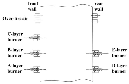
Figure 1.
350 MW boiler burners arrangement.
The structural configuration of the prototype LNASB burner utilized in the 350 MW unit boiler is illustrated schematically in Figure 2 [25]. This burner employs a dual-path air supply system: the primary air conveys pulverized coal, while the secondary air delivers the oxygen necessary for combustion. Upon passing through a swirl-generating device, the coal-laden primary air forms a rotating flow. Within the primary air duct, a coal concentrator separates this stream into four distinct, concentrated airflows. The secondary air system comprises inner, outer, tertiary, and center air passages, each equipped with vanes. Specifically, the outer secondary air duct incorporates tangentially arranged vanes with adjustable angles, whereas the inner secondary air duct features axially oriented vanes whose position can be modulated. The tertiary and center air ducts are fitted with fixed axial vanes. Swirl intensity was adjusted by synchronously adjusting the vane angle of the outer secondary air and the axial position of the inner secondary air vanes. Furthermore, eight air inlets are uniformly distributed along the inner secondary air duct, with damper mechanisms installed at each inlet to regulate the airflow rate.
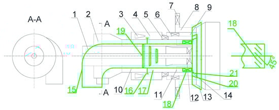
Figure 2.
LNASB burner and schematic diagram of advanced flame-stabilized burner structure: (1) central air duct; (2) coal conveying elbow; (3) inner secondary air inlet; (4) inner secondary air passage; (5) inner swirler vanes; (6) tertiary air vanes; (7) outer swirler vanes; (8) outer secondary air passage; (9) tertiary air duct; (10) primary air duct; (11) coal collector; (12) central air swirler; (13) outer air diffuser; (14) flame stabilization ring; (15) modified primary air duct; (16) slit air regulating valve; (17) slit air passage; (18) slit air swirl vanes; (19) triple-stage concentration ring; (20) inner secondary air diffuser; (21) slit air diffuser.
2.2. Novel Stable Combustion Burner
To enhance the operational flexibility of a 350 MW unit boiler firing low-grade coal, this research introduces an innovative swirl gas particle two-phase flow theory. Based on this approach, a retrofit strategy is developed for the boiler’s original LNASB burner, resulting in a novel combustion stabilizer. Figure 2 presents a simplified schematic of the modified burner configuration. The key structural revisions involve removing the central air pipe, coal concentrator, and coal delivery elbow inside the original primary air duct; installing a new straight-flow primary air pipe while maintaining the outlet area consistent with the prototype LNASB burner; integrating three-stage concentration rings within the new primary air pipe to enrich pulverized coal concentration. The lengths of the three-stage concentrating rings are 7/20d, 3/10d, and 1/5d, respectively, and the length of the gap air expansion opening is 13/20d. The structural retrofitting strategy incorporated two key modifications to enhance flow dynamics: first, the installation of vanes between the original and newly implemented primary air pipes, accompanied by the introduction of regulated gap air; second, the addition of divergent openings to the outer ducts conveying both the gap air and the inner secondary air. A comparative summary detailing the structural parameters for both the conventional LNASB burner and the novel stable combustion burner is systematically presented in Table 1. The fundamental operational principles governing the novel burner’s performance are elucidated as follows:

Table 1.
Burner structure parameters.
- (1)
- Stable Combustion
The synergistic interplay between the straight-flow primary air pipe and the three-stage concentration rings establishes a zone of high pulverized coal concentration in the central region of the burner outlet. This elevated coal concentration facilitates more rapid ignition upon contact with high-temperature flue gas, thereby optimizing the overall ignition conditions. Additionally, the refined nozzle cross-section, integrated with an enhanced divergent opening design, improves the flow field organization within the burner. This configuration fosters the development of an extensive and stable recirculation zone at the outlet, leading to a significant increase in combustion stability [25].
- (2)
- Low NOx Emissions
The novel stable combustion burner creates a high concentration coal distribution in the central region at the outlet. Within the recirculation zone, the particle volume flux of the coal is high, and the residence time is extended. This fuel-rich zone exhibits a low-oxygen, strongly reducing atmosphere. Combustion of coal under reducing conditions can effectively reduce the generation of fuel-type NOx.
- (3)
- Prevention of High-Temperature Corrosion
The novel stable combustion burner achieves radial air-staging (rich-lean separation). The outlet cross-section of the primary air pipe features a coal distribution characteristic of being “rich inside and lean outside.” This distribution pattern helps prevent coal particles from being thrown towards the side walls during combustion, thereby maintaining an oxidizing atmosphere near the side walls. This effectively avoids high-temperature corrosion of the side wall water-cooled tubes caused by a reduced excess air ratio in the main combustion zone.
- (4)
- Slagging Prevention
In the novel stable combustion burner, the concentrated pulverized coal is ejected from the burner center with relatively low tangential and radial velocities. Concentrating most of the coal for combustion in the center of the burner is beneficial for preventing slagging.
3. Methodology
3.1. Test Criteria
The outlet flow field characteristics of the novel stable combustion burner under different primary air velocities were investigated through gas particle two-phase flow cold-state experiments. In actual boiler operation, the interaction between the flow fields of adjacent burners is minimal, and each burner operates independently. Therefore, a scaled experimental setup for a single burner was constructed to study the gas particle flow characteristics at the burner outlet. In previous experiments and studies, we have verified that the cold-state test results are consistent with the actual combustion conditions [26,27].
The scaling methodology for the model burner’s geometric design and experimental parameter determination in the gas particle two-phase flow investigations adhered to established similitude principles to ensure dynamical similarity. Key criteria included:
- (1)
- Based on the actual burner dimensions of the 350 MW unit boiler, the scale ratio of the model burner used in the two-phase experiments to the actual burner was 1:7, meaning the inner diameter of each air duct in the actual burner was seven times that of the model.
- (2)
- In the gas particle two-phase flow experiments, due to the limited model pipe diameter, the turbulent kinetic energy of the internal flow is relatively high, leading to a decrease in the second critical Reynolds number from 105 to 104 [20,21,22,28]. The calculated Reynolds numbers in all air passages of the model burner for the gas particle two-phase flow experiments were greater than 104, indicating that the flow in each air duct was within the second self-modeling region, satisfying the dynamic similarity requirements for airflow mixing characteristics.
- (3)
- In the gas particle two-phase flow experiments, the momentum ratio of the airflow in each duct of the model burner was consistent with that during actual operation of the 350 MW unit boiler burner.
- (4)
- In forced flow conditions where the transported particles have diameters below 200 μm, the effect of the Froude number on gas–particle flow dynamics can be considered negligible. This study utilized glass beads with a size distribution of 0.1–100 μm and a mean diameter of 50 μm, falling well below this threshold. An induced draft fan provided the forced flow to carry the particles, thereby satisfying the conditions under which the Froude criterion may be disregarded.
3.2. Gas/Particle Two-Phase Experiment
Figure 3 illustrates the schematic layout and measurement point distribution of the gas–particle two-phase cold-flow experimental system. The setup comprises an induced draft fan, a cyclone separator, a Phase Doppler Anemometer (PDA), a screw feeder, a scaled model burner, a correspondingly scaled furnace section, and interconnecting piping. The induced draft fan establishes a negative-pressure (−50Pa) environment within the furnace model, drawing air streams from each supply duct into the chamber. Air mass flow rates are regulated by adjusting ball valves, while U-tube manometers installed on each air supply line enable the determination of actual flow rates via pressure reading conversions. The screw feeder introduces glass beads into the primary air pipe, generating a particle-laden airflow that simulates actual pulverized coal transport. To accurately simulate the velocity lag inherent in pneumatic transport of pulverized coal, a gas particle slip coefficient of 0.8 was employed [29]. This setting maintained the particle velocity at 80% of the local air velocity within the primary air duct. A cyclone separator was integrated into the system to capture and recycle the glass beads after their passage through the test section, facilitating their repeated use. The sampling interval of the PDA for each measurement point is 20 s. The number of collected samples is 20,000, and the data represents the average value. The particle size distribution of the beads, shown in Figure 4, ranges from 0.1 to 100 μm with a mean diameter of 50 μm. Hollow beads smaller than 8 μm served as airflow tracers, while particle beads ranging from 8 to 100 μm simulated pulverized coal particles [30]. To maintain accuracy despite the potential loss of finer particles, the bead inventory was replenished periodically based on real-time monitoring of the particle size distribution.
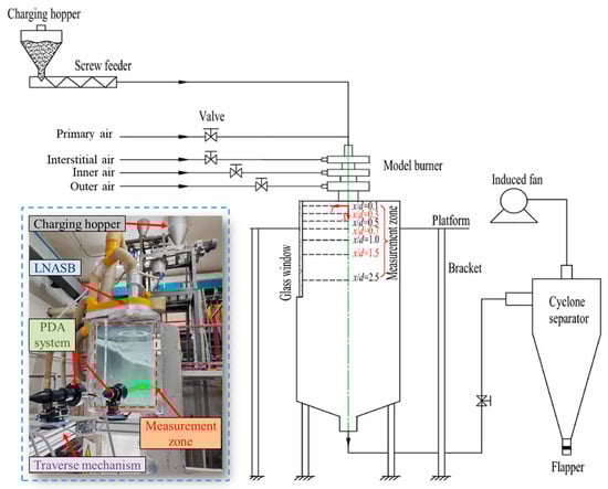
Figure 3.
Cold-state gas particle two-phase flow test system and measuring point distribution.
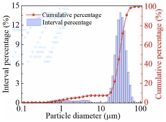
Figure 4.
Particle size distribution of glass microspheres.
Figure 3 illustrates the spatial distribution of measurement points employed in the experimental study. The characteristic dimension d denotes the inner diameter (0.146 m) of the outer secondary air divergent opening of the model burner. The axial distance from any measurement point to the burner outlet section is defined as x, while the radial distance to the burner central axis is designated as r. In the immediate vicinity of the burner nozzle, intense mixing of airflow streams occurs post ejection, leading to considerable fluctuations in both gas velocity and particle mass flux within this region. To enable a more precise analysis of the gas particle two-phase flow characteristics at the burner exit, a higher density of measurement points with reduced spacing was deployed near the nozzle. Furthermore, to mitigate potential interference from wall or optical edge effects on laser-based measurement accuracy, the initial measurement section was established at a normalized distance of x/d = 0.1. A total of seven measurement sections were arranged along the burner’s central axis at specific dimensionless locations: x/d = 0.1, 0.3, 0.5, 0.7, 1.0, 1.5, and 2.0. Within each cross-section, 36 measurement points were systematically distributed along the radial direction, culminating in a comprehensive total of 252 discrete measurement locations across the experimental domain.
A non-intrusive, three-dimensional Phase Doppler Anemometry (PDA) system (Dantec Dynamics, Copenhagen, Denmark) was employed to characterize the gas particle two-phase flow. The system delivers high-precision measurements, with uncertainties of 1% for mean velocity, 4% for particle size, and 30% for particle volume flux. Its operational ranges encompass particle sizes from 0.5 to 1000 μm and velocities spanning from −500 to 500 m/s [31]. Minor airflow fluctuations (approximately 5%), attributed to variations in line voltage, ambient pressure, and temperature from the induced draft fan, were observed to have a negligible impact on the final measurement outcomes. After calculation, the impact is approximately 3%, which falls within the 5% fluctuation range of the result’s effect. The PDA system successfully captured the complete three-dimensional mean and fluctuating velocity fields (axial, tangential, and radial) for both phases, in addition to detailed particle size distributions [32]. A fundamental principle of the PDA technique is that particle concentration is not a direct measurement. It is instead computed by counting the number of particles passing through a defined measurement volume per unit time and integrating this data with the corresponding particle velocity and size information.
3.3. Test Parameters and Analysis Methods
- (1)
- In this study, to quantitatively characterize the rotational characteristics of the gas particle two-phase flow, the calculation of the swirl number (S) was introduced. As an important dimensionless parameter describing the rotational intensity of the flow field, the swirl number is widely used in the study of burner flow characteristics. Its magnitude directly relates to the flow stability, combustion efficiency, and pollutant emission characteristics within the furnace. The gas-phase swirl number Sg (Equation (1)) is calculated based on the velocity distribution and angular momentum of the airflow, reflecting the variation pattern of the gas rotational intensity downstream of the burner nozzle. The particle-phase swirl number Sp (Equation (2)) is solved considering the inertia of pulverized coal particles and the forces exerted by the airflow, revealing the rotational response of coal particles under gas particle coupling effects. The determination of both two-phase swirl numbers is based on synchronously measured experimental data in the near-field region of the nozzle (this study selects the x/d = 0.1 cross-section), ensuring that the calculated results representatively reflect the initial flow characteristics at the nozzle [33].
The symbols used in this study are defined as follows: and denote the gas-phase and particle-phase densities (kg/m3), respectively; and represent the axial velocities (m/s) of the gas and particle phases; and correspond to the tangential velocities (m/s) of each phase; and indicates the particle volume flow rate at the measurement point, with units of m3/(m2·s).
- (2)
- To evaluate the mixing effectiveness of the airflow at the burner outlet, the turbulence intensity (T) is introduced, and its computational method is provided in Formula (3) [25].
The following symbols are defined for the velocity components analyzed in this study: represents the axial fluctuating velocity (m/s), denotes the radial fluctuating velocity (m/s), and signifies the tangential fluctuating velocity (m/s). These fluctuating velocity components were directly measured using a Phase Doppler Anemometry (PDA) system, which has a measurement uncertainty of 1% for velocity. Additionally, U indicates the resultant mean velocity of the three-dimensional airflow, calculated from the time-averaged velocity components.
- (3)
- The boundary of the recirculation zone is constructed by sequentially connecting velocity boundary points, which are identified as the positions of zero axial velocity at each dimensionless axial station (x/d). To minimize the influence of near-wall flow reversal, these points are selected in close proximity to the burner’s central axis. The region enclosed by this boundary line is characterized by negative axial velocities, indicative of the recirculating flow. Conversely, outside this boundary, the axial velocity assumes positive values, confirming the presence of forward flow.
The gas particle flow characteristics of the novel stable combustion burner were investigated under various primary air velocities, with the full-load operational parameters serving as the benchmark condition for designing the experimental working conditions. The experimental parameters for the novel stable combustion burner under different primary air velocities are listed in Table 2.
Table 2.
Experimental parameters of advanced flame-stabilized burner under different primary air velocities.
4. Results
4.1. Recirculation Zone and Velocity Boundary
Table 2 summarizes the swirl numbers of the novel stable combustion burner under varying primary air velocities. As the primary air velocity rises from 9 m/s to 11 m/s, a clear decreasing trend is observed: the gas-phase swirl number drops from 0.33 to 0.22, while the particle-phase swirl number declines from 0.38 to 0.25. This reduction is primarily due to the center-feed coal design of the burner, which contributes to a predominantly axial flow pattern in the primary air upon exiting the nozzle, thereby constraining the development of strong swirl.
The morphological evolution of the recirculation zone boundary at the burner outlet, as a function of primary air velocity, is depicted in Figure 5 and Table 3. At a primary air velocity of 9 m/s, a well-defined central recirculation zone (CRZ) is established, exhibiting a length of 0.9 d and a width of 0.3 d. The position of its lower boundary, located beneath the burner centerline, confirms its central nature. Increasing the velocity to 10 m/s triggers a transition; the recirculation zone becomes annular and narrows to a width of 0.2 d, while its length remains at 0.9 d, and the lower boundary shifts above the centerline. A further increase to 11 m/s results in a more compact annular recirculation zone, with the length reduced to 0.3 d and the width unchanged. These morphological changes demonstrate that the straight-flow primary air velocity is a critical factor governing the size and structure of the recirculation zone. Specifically, higher primary air velocities promote a shift from a central to an annular recirculation zone and lead to a general reduction in its dimensions. The underlying mechanism is that increased air velocity improves the momentum (rigidity) of the central airflow, which impedes the entrainment of the primary air by the swirling secondary air and suppresses the formation of a stable recirculation zone near the centerline. Based on previous conclusions, it is understood that according to the results obtained from hot-state industrial tests, to maintain an adequate high-temperature flue gas recirculation zone essential for stable ignition, an excessively high primary air velocity should be avoided in the operation of this novel burner [26,27].
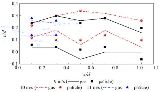
Figure 5.
Recirculation zone boundary under different primary air velocities.
Table 3.
The length, width, and shape of the recirculation zone under different primary air velocities. Recirculation zone boundary under different primary air velocities.
4.2. Gas Particle Two-Phase Flow Velocity Distribution
Figure 6 depicts the spatial distribution of the time-averaged axial velocity at the outlet of the novel stable combustion burner across a range of primary air velocities. Analysis indicates that elevating the primary air velocity results in a considerable decrease in the swirl numbers for both gas and particle phases. Within the initial development zone (x/d = 0–0.3), the axial velocity profile consistently demonstrates a dual-peak structure under all tested conditions. The dominant peak, situated near the burner centerline, originates from the primary air and pulverized coal stream, whereas the subordinate peak, located radially outward, is induced by the secondary airflow. A region of negative axial velocity is observed adjacent to r/d = 0.1, signifying local flow reversal. With an increase in primary air velocity, the magnitude of the primary peak intensifies, while the secondary peak’s position and amplitude remain largely invariant. Concurrently, the inception point of the negative velocity zone shifts away from the centerline, and its spatial extent contracts notably. At the x/d = 0.5–0.7 cross-section, the flow reversal zone vanishes almost for the case with an 11 m/s primary air velocity, suggesting a transition from a central recirculation zone to an annular configuration accompanied by a reduction in its size at higher primary air velocities. Further downstream at x/d = 1.0, the velocity distribution evolves into a single-peak pattern. Notably, under the 11 m/s condition, this conparticleated peak is located proximate to the central axis and exhibits a significantly higher magnitude compared to other cases, reflecting a strengthened axial momentum and suppressed radial dispersion of the flow. In the far-field region (x/d = 1.5–2.5), the distinctions between the axial velocity profiles under different primary air velocities diminish, and the distribution curves flatten, indicating a more uniform flow development downstream.
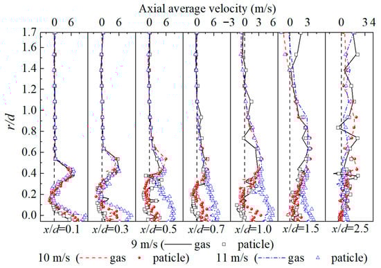
Figure 6.
Axial mean velocity distribution at burner exit under different primary air velocities.
Figure 7 illustrates the radial positions corresponding to the maximum positive axial velocity under varying primary air velocities. At the nozzle cross-section, the axial velocity profile exhibits a bimodal distribution, with peak locations remaining consistent across the different primary air conditions. As the airflow propagates downstream, interaction and mixing occur between flows from distinct air passages. For all three primary air velocities investigated, complete integration of the primary and secondary air streams is observed at the dimensionless axial distance x/d = 1.0, marked by the coalescence of the dual velocity peaks into a single, unified peak, signifying the conclusion of the mixing process. Following mixture completion, the radial position of the resultant peak for the 11 m/s and 9 m/s cases are proximate to each other, yet both are situated significantly farther from the burner centerline compared to the peak position in the 10 m/s scenario. The smallest radial coordinate r for the peak is associated with the highest primary air velocity of 11 m/s. Under this condition, the consolidated velocity peak is not only located closest to the central axis but also demonstrates a greater magnitude relative to the other operational conditions. These findings collectively suggest that an increase in primary air velocity contributes to a longer axial penetration of the mixed airflow, leads to a higher concentration of particles near the centerline, and concurrently regulates the radial dispersion capability of the flow.
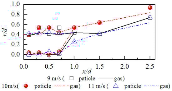
Figure 7.
Position of maximum positive axial velocity under different primary air velocities.
The axial normalized mean velocity profiles at the outlet of the novel stable combustion burner under different primary air velocities are shown in Figure 8. The normalized mean velocity is a dimensionless number obtained by dividing the velocity at each point by the maximum positive velocity, facilitating the comparison of relative distribution characteristics. For the novel stable combustion burner, as the primary air velocity increases, the swirl numbers of both the gas phase and the particle phase decrease significantly, which is consistent with the trend shown in Figure 6. Within the range of x/d = 0–0.3, the axial normalized mean velocity under the three primary air velocity conditions exhibits a bimodal distribution. The peak near the burner centerline is caused by the primary air/pulverized coal flow, while the peak away from the center is caused by the secondary air flow. Near r/d = 0.1, the axial normalized mean velocity is negative, indicating the presence of a recirculation zone. As the primary air velocity increases, the normalized peak value of the main peak (caused by the primary air/pulverized coal) increases, while the position and magnitude of the secondary peak (caused by the secondary air) remain essentially unchanged. The starting point of the negative velocity region moves away from the burner centerline, and its range becomes smaller. At the x/d = 0.5–0.7 cross-section, the negative velocity region has disappeared for the case with a primary air velocity of 11 m/s, indicating that for the novel stable combustion burner, selecting a higher primary air velocity causes the central recirculation zone to transition to an annular recirculation zone, and the range of the recirculation zone shrinks. At the x/d = 1.0 cross-section, the radial distribution of the axial normalized mean velocity under different conditions transforms into a single-peak structure. It is worth noting that when the primary air velocity is 11 m/s, the mixed peak is located near the central axis of the burner outlet, and its normalized peak value is more prominent compared to the other conditions. This indicates that when the burner operates under this condition, the axial movement tendency of the airflow in the central region is stronger, and the tendency for outward diffusion is weaker. At the x/d = 1.5–2.5 cross-sections, the differences in the axial normalized mean velocity distribution of the two-phase flow at the burner outlet under different primary air velocities are small; the velocity distribution curves tend to flatten, reflecting a homogenization trend of the flow in the downstream region. Overall, the axial normalized velocity profiles share consistent physical characteristics with the axial absolute velocity distribution, verifying the axial flow characteristics of the burner under different primary air velocities.
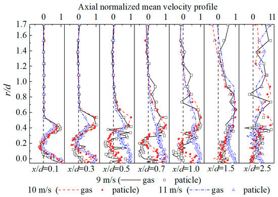
Figure 8.
Axial normalized mean velocity profile at burner exit under different primary air velocities.
The radial average velocity distribution at the outlet of the novel stable combustion burner under different primary air velocities is shown in Figure 9. Within the range of x/d = 0.1–1.0, significant negative values in the radial average velocity for both gas and particle phases are observed near r/d = 0.35 under different loads, indicating that the two-phase flow moves towards the burner centreline in this region. Combined with Figure 6, it can be seen that the region where negative radial average velocities occur essentially coincides with the recirculation zone, suggesting that the two-phase flow within the recirculation zone exhibits both a tendency to reflux axially and a tendency to converge towards the centerline. During actual boiler operation, the convergence of pulverized coal towards the recirculation zone facilitates its full contact with high-temperature flue gas. Owing to the straight-flow (non-swirling) design of the primary air in the novel stable combustion burner, the radial average velocity near the burner centerline remains relatively low. This velocity exhibits a further decreasing trend as the primary air velocity increases, indicating that a higher primary air momentum constrains the radial diffusion capability of the pulverized coal-laden stream at the outlet. Within the downstream region of x/d = 1.5–2.5, the radial average velocity attenuates to approximately 0 m/s.
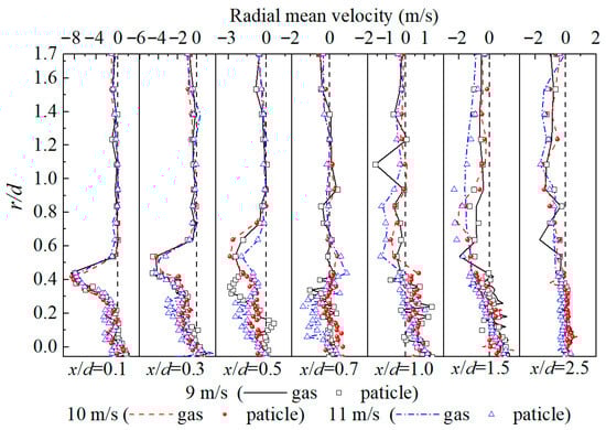
Figure 9.
Radial mean velocity distribution at burner exit under different primary air velocities.
Figure 10 depicts the tangential time-averaged velocity distribution at the outlet of the novel stable combustion burner under varying primary air velocities. The tangential velocity profiles exhibit similar shapes across the tested primary air velocity range. Externally to the burner nozzle, the radial distribution of the tangential velocity for the two-phase flow manifests a distinct unimodal characteristic. The peak value of this distribution is consistently located within the region dominated by the swirling secondary airflow. This distribution arises from the center-feed coal design, which results in comparatively low tangential velocities within the primary air-dominated flow zone adjacent to the central axis. In the near-nozzle region (x/d = 0.1–0.3), the tangential velocity distribution curves for the two-phase flow are essentially identical under different primary air velocities, maintaining similar peak positions and magnitudes. Within this region, the tangential average velocity exhibits minimal decay as the flow progresses downstream from the nozzle, indicating that the gas particle two-phase flow sustains a relatively stable rotational capability in this area. As the flow develops further to x/d = 0.5–1.5, the rotational intensity of the two-phase flow becomes comparable under different primary air velocities. This phenomenon is attributed to the dominant role of the swirling secondary air in governing the tangential velocity distribution, while the straight-flow primary air primarily influences the overall axial momentum of the two-phase flow. A notable observation is that a primary air velocity of 10 m/s yields the highest peak tangential average velocity radially, indicating the strongest rotational ability of the two-phase flow under this condition. By the time the flow reaches x/d = 2.5, the tangential average velocities for all primary air velocity cases decay to approximately 0 m/s.
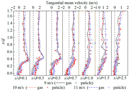
Figure 10.
Tangential mean velocity distribution at burner exit under different primary air velocities.
Figure 11 illustrates the radial positions corresponding to the peak positive tangential velocity at the outlet of the novel stable combustion burner across the tested primary air velocities. Within the near-nozzle region (x/d = 0–0.7), the locus of the maximum tangential velocity remains consistent under all conditions, consistently located near r/d = 0.3. Beyond x/d = 0.7, a marked outward migration of the peak tangential velocity position is observed with increasing axial distance, characterized by a rapid increase in its radial coordinate (r/d). This shift occurs because the maximum tangential velocity is predominantly generated within the swirling secondary air flow region, given the straight-flow nature of the primary air. Consequently, as the combined airflow expands radially downstream, the point of peak tangential velocity exhibits a progressively outward trend for all primary air velocities assessed.
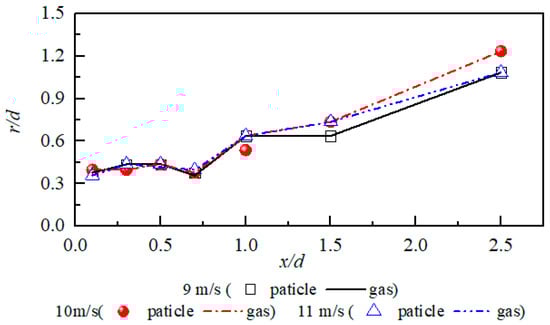
Figure 11.
Position of maximum tangential velocity under different primary air velocities.
The tangential normalized mean velocity profiles at the outlet of the novel stable combustion burner under different primary air velocities are shown in Figure 12. The shapes of the tangential normalized mean velocity distribution curves under different primary air velocities are similar, consistent with the trend in Figure 10. Outside the burner nozzle, the tangential normalized mean velocity of the two-phase flow exhibits a single-peak distribution along the radial direction, with the peak always located in the swirling secondary air region. Near the nozzle (x/d = 0.1–0.3), the shapes of the tangential normalized mean velocity distribution curves for the two-phase flow under different primary air velocities are basically identical, and their peak positions and magnitudes are also basically the same. Within this range, as the two-phase flow moves away from the nozzle cross-section, the tangential normalized mean velocity does not show a significant decay trend, indicating that the gas particle two-phase flow maintains a relatively stable rotational capability in this area. When the flow develops to x/d = 0.5–1.5, the rotational intensity of the two-phase flow is similar under different primary air velocities. This is because the swirling secondary air plays a dominant role in the tangential velocity distribution, while the direct-flow primary air mainly affects the overall axial movement component of the two-phase flow. It is noteworthy that when the primary air velocity is 10 m/s, the peak value of the tangential normalized mean velocity along the radial direction is the largest, and the two-phase flow exhibits the strongest rotational capability. At x/d = 2.5, the tangential normalized mean velocities of the two-phase flow under different primary air velocities all decay to around zero, reflecting the complete dissipation of rotational momentum in the downstream region. Overall, the tangential normalized mean velocity profiles share consistent physical characteristics with the distribution in Figure 10, verifying the tangential flow characteristics of the burner under different primary air velocities.
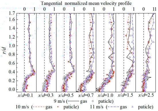
Figure 12.
Tangential normalized mean velocity profile at burner exit under different primary air velocities.
4.3. Turbulence Intensity
The distribution of turbulence intensity at the outlet of the novel stable combustion burner under different primary air velocities is shown in Figure 13. The turbulence intensity distribution of the airflow at the burner outlet is non-uniform, exhibiting high-level fluctuations within the range of r/d = 0–0.4. It can be observed that within the range of x/d = 0.1–1.0, the region of intense turbulence fluctuation basically coincides with the recirculation zone. The turbulence intensity exhibits a bimodal distribution along the radial direction, with a higher peak located at the burner centerline (r/d = 0.12) with a peak value of 3.5, and a lower peak distributed at the junction area between the primary air and the gap air (r/d = 0.24) with a peak value of 2.1. As the primary air velocity increases, both peaks show an enhancing trend: the higher peak increases from 3.5 to 4.0 (a 14% increase), and the lower peak increases from 2.1 to 2.5 (a 25% increase). The emergence of the aforementioned flow field characteristics stems from two reasons. First, the increase in primary air velocity leads to a greater velocity difference between the primary air and the swirling gap air, significantly enhancing the turbulent perturbation in the shear layer of the airflow. Second, the high-velocity primary air increases the velocity component of particles towards the center, and the increased particle concentration in the centerline region intensifies the particle collision and energy exchange processes. When the two-phase flow develops to x/d = 1.5–2.0, it reaches a position relatively far from the burner nozzle section. The turbulence intensity along the radial direction shows only a single peak near the centerline, whose magnitude is primarily determined by the overall axial velocity component of the airflow. The peak position is at r/d = 0.03, and the peak value is 3.0. As the primary air velocity increases, the turbulence intensity of the two-phase flow in this region increases.
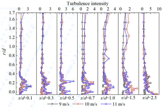
Figure 13.
Turbulence intensity distribution at burner exit under different primary air velocities.
4.4. Particle Volumetric Flux Distribution
Figure 14 presents the distribution of particle volume flux at the outlet of the novel stable combustion burner under varying primary air velocities. In all operating conditions, the particle volume flux displays a distinct unimodal profile radially. As illustrated by the peak positions across different cross-sections in Figure 15, within the region from x/d = 0.1–0.5, the maximum particle volume flux consistently occurs near the burner centerline. Furthermore, the magnitude of this peak exhibits a positive correlation with increasing primary air velocity. This behavior results from the enhanced centripetal velocity component imparted to pulverized coal particles as they interact with the three-stage concentration rings under the influence of high-velocity, straight-flow primary air, leading to a significant accumulation of particles along the central axis. Concurrently, in the vicinity of r/d = 0.2, the particle volume flux assumes negative values, signaling the presence of a particle reflux phenomenon. A comparative analysis of Figure 5 and Figure 14 confirms that this zone of negative flux aligns spatially with the recirculation zone at the burner outlet. The intensity of the negative peak is directly influenced by the extent of the recirculation zone; for instance, a primary air velocity of 9 m/s yields the most pronounced negative peak, indicating optimal particle entrainment within the recirculation zone under this condition. As the gas particle flow develops further downstream to x/d = 0.5–1.0, an increase in primary air velocity from 9 m/s to 11 m/s leads to a higher particle volume flux near the centerline, accompanied by an accelerated decay rate radially. This pattern suggests that elevated primary air velocity improves particle concentration in the central region while concurrently restraining its radial dispersion. In practical burner operation, the radial diffusion capability of pulverized coal particles is critical for achieving uniform flame distribution and full spatial utilization of the furnace volume. Hence, operational strategies should aim not only to enrich coal concentration centrally but also to preserve an adequate radial diffusion capacity for stable and efficient combustion.
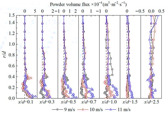
Figure 14.
Particle volume flux distribution at burner exit under different primary air velocities.
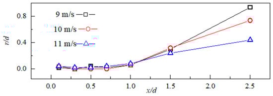
Figure 15.
Position of maximum particle volume flux under different primary air velocities.
5. Discussion
With an increase in the primary air velocity of the novel stable combustion burner, the swirl numbers associated with both the gas and particle phases exhibit a marked reduction. Variations in primary air velocity predominantly influence the axial velocity distribution of the two-phase flow at the burner outlet, while having a comparatively minor impact on the radial and tangential velocity profiles. Adjusting the primary air velocity allows for effective modulation of the recirculation zone’s morphology and dimensions at the burner exit. Based on previous conclusions, it is understood that according to the results obtained from hot-state industrial tests, as the primary air velocity is raised from 9 m/s to 11 m/s, the recirculation zone transitions from an extensive central formation to a more confined annular structure [26,27]. This increase in velocity improves the axial propagation distance of the mixed flow, elevates particle concentration adjacent to the centerline, and diminishes its radial diffusion capacity. From the perspective of recirculation zone morphology: an increase in primary air velocity enhances the rigidity of the airflow near the centerline, making it more difficult for the secondary air to entrain the primary air. This suppresses the formation of the recirculation zone near the centerline, consequently causing a transition of the recirculation zone from a central type to an annular type. From the perspective of diffusion effects: an excessively high primary air velocity increases the axial propagation distance of the mixed jet, raises the particle concentration near the centerline, and simultaneously weakens its radial diffusion capability. At a specific primary air velocity of 10 m/s, the burner outlet develops a sizable annular recirculation zone capable of delivering sufficient energy for reliable ignition of low-grade coal. Under this condition, the particle volume flux attains high values near the centerline, while the recirculation zone itself registers significant negative flux values. The accumulation of pulverized coal in the central region contributes to the establishment of a high-temperature, oxygen-depleted, reducing atmosphere, which effectively suppresses the generation of fuel-type NOx. Accordingly, setting the operational parameters of the novel burner based on the 10 m/s primary air velocity condition from gas particle two-phase flow tests is strongly recommended.
6. Conclusions
To enhance the operational flexibility of a 350 MW unit boiler firing low-grade coal, this research introduces an innovative stable combustion theory. The gas particle two-phase flow characteristics at the outlet of a novel burner designed based on this theory were systematically investigated using Phase Doppler Anemometry (PDA) under varied primary air velocities. The study aims to elucidate the influence of primary air velocity on the flow dynamics and combustion stability, with key findings summarized as follows:
- (1)
- The novel swirl stable combustion theory requires only partial retrofitting rather than full burner replacement. Key structural revisions include removing the original central air pipe, coal concentrator, and coal delivery elbow; installing a straight-flow primary air duct while maintaining the outlet area consistent with the prototype LNASB burner; integrating three-stage concentration rings to enrich pulverized coal density; deploying vanes between the original and new primary air ducts with introduced gap air; and adding divergent openings to the outer ducts of both the gap air and inner secondary air. These targeted modifications minimize construction scope while optimizing flow dynamics.
- (2)
- Variations in primary air velocity significantly modulate the morphology and dimensions of the recirculation zone. At 9 m/s, a central recirculation zone forms, transitioning to an annular configuration at 10 m/s and 11 m/s. As velocity increases, the recirculation zone not only shifts from central to annular but also contracts in size. Consequently, a primary air velocity of 10 m/s appears to provide the most stable flow behavior under cold experimental conditions.
- (3)
- When the primary air velocity reaches 11 m/s, the recirculation zone becomes annular and reduced in scale. At the x/d = 1.0 cross-section, axial velocity distribution transitions to a unimodal profile with a distinct peak, suppressing pulverized coal radial diffusion. Higher primary air velocities weaken radial airflow dispersion, while tangential velocity peaks at 10 m/s, indicating enhanced swirl stability. Additionally, turbulence intensity strengthens markedly with increasing velocity and displays a bimodal distribution within the recirculation zone.
- (4)
- A primary air velocity of 9 m/s yields the most prominent negative peak in particle volume flux, reflecting the recirculation zone’s strongest particle entrainment capacity under this condition. Elevated pulverized coal concentration near the burner centerline contributes to a high-temperature, oxygen-lean reducing atmosphere, effectively curbing fuel-type NOx formation. At 11 m/s, central particle concentration peaks but radial decay accelerates, constraining diffusion capability. Thus, operational parameters based on the 10 m/s condition are advised to balance concentration and diffusion.
To further research the proposed novel stable combustion theory and the novel stable combustion burner, future work will involve experiments under low-load conditions. Subsequent investigations will focus on characterizing the low-load stable combustion performance of the novel burner and the associated gas particle two-phase flow dynamics at its outlet. These efforts are directed toward elucidating the underlying mechanisms governing stable combustion in swirl burners, thereby providing a critical foundation for future optimization and retrofitting initiatives.
Author Contributions
Conceptualization, X.L.; Methodology, L.D. and W.W.; Software, N.Z.; Validation, N.Z. and D.X.; Formal analysis, D.X. and Z.C.; Investigation, L.D. and D.X.; Resources, Z.L.; Data curation, W.W.; Writing—original draft, W.W.; Writing—review & editing, Z.C.; Visualization, N.Z.; Supervision, Z.L.; Project administration, X.L.; Funding acquisition, Z.L. All authors have read and agreed to the published version of the manuscript.
Funding
This work was supported by the CR Power Theory R&D Program (Grant No. CRP-R&D-LX-2025-031).
Data Availability Statement
The original contributions presented in this study are included in the article. Further inquiries can be directed to the corresponding authors.
Conflicts of Interest
Xiangjun Long, Leikai Deng and Nan Zhang were employed Hubei Chibi Electric Power Co., Ltd. Defu Xin was employed by Beijing Yelian Theory Co., Ltd. The remaining authors declare that the research was conducted in the absence of any commercial or financial relationships that could be construed as a potential conflict of interest.
References
- Jie, D.F.; Xu, X.Y.; Guo, F. The future of coal supply in China based on non-fossil energy development and carbon price strategies. Energy 2021, 220, 119644. [Google Scholar] [CrossRef]
- Zheng, M.H.; Song, M.H.; Wang, J.X. Transition targets and technical analysis of coal-fired units under the “Dual Carbon” goal. Guangdong Electr. Power 2022, 35, 14–22. [Google Scholar]
- Wang, Z.; Kong, Y.H.; Li, W. Review on the development of China’s natural gas industry in the background of “carbon neutrality”. Nat. Gas Ind. B 2022, 9, 132–140. [Google Scholar] [CrossRef]
- Zhou, D.Q.; Ding, H.; Wang, Q.W.; Su, B. Literature review on renewable energy development and China’s roadmap. Front. Eng. Manag. 2021, 8, 212–222. [Google Scholar] [CrossRef]
- Wang, Q.H.; Liu, J.Z.; Fan, H.B.; Qin, T.M.; Huang, Y.; Wang, Y.B.; Wang, H.P. New flexible coal-fired power generation theory supporting China’s energy transition: Boiler system and turbine generator system. Proc. CSEE 2024, 44, 7136–7167. [Google Scholar]
- Jafarizadeh, H.; Yamini, E.; Zolfaghari, S.M.; Esmaeilion, F.; Assad, M.E.; Soltani, M. Navigating challenges in large-scale renewable energy storage: Barriers, solutions, and innovations. Energy Rep. 2024, 12, 2179–2192. [Google Scholar] [CrossRef]
- Liu, H.Y.; Han, P.C.; Zhang, Y. Coupling coordination between clean power supply and electrification of energy consumption and its impact on carbon emission reduction. Ecol. Econ. J. 2025, 41, 33–42. [Google Scholar]
- Ouyang, Z.Q.; Wang, H.S.; Lu, Q.G.; Zhu, S.J.; Zeng, J.W. Advances in deep peak regulation theory for pulverized coal-fired boiler power units. Proc. CSEE 2023, 43, 8772–8790. [Google Scholar]
- Wang, Y.Q.; Zhou, Y.G.; Bai, N.M.; Han, J.C. Experimental investigation of the characteristics of NOx emissions with multiple deep air-staged combustion of lean coal. Fuel 2020, 280, 118716. [Google Scholar] [CrossRef]
- Yan, X.R.; Gao, X.; Yu, P.F.; He, J.L.; Zhou, X.O.; Zhang, P.W.; Xiang, J.; Liu, J.L.; Guo, J.X.; Huang, Y.B. Safety challenges and countermeasures for flexible operation of coal-fired power units. Proc. CSEE 2025, 45, 4318–4336. [Google Scholar]
- Wang, C.W.; Wang, C.A.; Jia, X.W.; Gao, X.Y.; Wang, P.Q.; Feng, Q.Q.; Che, D.F. Experimental investigation on combustion characteristics and kinetics during Co-Firing bituminous coal with ultra-low volatile carbon-based particle fuels. J. Energy Inst. 2021, 95, 87–100. [Google Scholar] [CrossRef]
- Sui, B.W.; Zhao, X.P.; Chao, J.K.; Xu, D.P. Operational optimization method for supercritical boilers burning inferior coal based on improved extreme learning machine. Clean Coal Theory 2024, 30, 592–599. [Google Scholar]
- Liu, R.Q.; Jia, W.F. Exploration of inferior coal blending theory and management methods under spot trading mode. Electr. Power Saf. Theory 2025, 27, 63–69. [Google Scholar]
- Wang, J.X. Impact analysis of inferior coal blending and air distribution on operational economy of 330 MW boiler. Power Syst. Eng. 2023, 39, 25–28. [Google Scholar]
- Lin, B.Q. Achievements of China’s power development during the 13th Five-Year Plan and prospects for the 14th Five-Year Plan. China Electr. Power 2020, 965, 22–23. [Google Scholar]
- Du, W.; Zhou, S.Q.; Qiu, H.C.; Zhao, J.G.; Fan, Y.T. Experiment and numerical study of the combustion behavior of hydrogen-blended natural gas in swirl burners. Case Stud. Therm. Eng. 2022, 39, 102468. [Google Scholar] [CrossRef]
- Zhang, G.C.; Zhou, K.; Lu, F. Discussions on deep peaking theory of coal-fired power plants. Therm. Power Gener. 2014, 46, 17–23. [Google Scholar]
- Hui, J.C.; Zhu, S.J.; Li, Z.Y.; Lin, J.G.; Cao, X.Y.; Lyu, Q.G. Experimental study on peak shaving during preheating combustion for different coal ranks: Thermal modification and variable load operation. Fuel 2024, 373, 132324. [Google Scholar] [CrossRef]
- Song, M.H.; Huang, Y.; Huang, Q.; Li, S.Q. Discussion on low-load stable combustion theory of swirl pulverized-coal burner. Proc. CSEE 2021, 41, 4552–4566. [Google Scholar]
- Zeng, L.Y.; Li, Z.Q.; Zhao, G.B.; Li, J.; Zhang, F.C.; Shen, S.P.; Chen, L.Z. The influence of swirl burner structure on the gas/particle flow characteristics. Energy 2011, 36, 6184–6194. [Google Scholar] [CrossRef]
- Jing, J.P.; Li, Z.Q.; Zhu, Q.Y.; Chen, Z.C.; Wang, L.; Chen, L.Z. Influence of the outer secondary air vane angle on the gas/particle flow characteristics near the double swirl flow burner region. Energy 2011, 36, 258–267. [Google Scholar] [CrossRef]
- Jing, J.P.; Li, Z.Q.; Wang, L.; Chen, L.Z.; Yang, G.H. Influence of secondary air mass flow rates on gas/particle flow characteristics near the swirl burner region. Energy 2011, 36, 3599–3605. [Google Scholar] [CrossRef]
- Xu, P.Z.; Liu, P.B.; Chen, J.H.; Che, F. Experimental Study on NOx Emission Regulation of LNASB Burner for 660MW Boiler. Power Gener. Air Cond. 2017, 38, 16–21. [Google Scholar]
- Fan, W.D.; Lin, Z.C.; Li, Y.Y. Experimental flow field characteristics of OFA for large-angle counter flow of fuel-rich airflow combustion theory. Appl. Energy 2010, 87, 2737–2745. [Google Scholar] [CrossRef]
- Wang, Y.F.; Li, Z.Q.; Huang, C.C.; Liu, H.C.; Feng, Y.; Du, X.Y. Influence of central coal feed swirl combustion theory on wide-load range performance of burners, based on gas/particle flow characteristics. Energy 2025, 320, 135404. [Google Scholar] [CrossRef]
- Li, Z.Q.; Jing, Q.P.; Liu, K.H.; Chen, Z.C.; Liu, C.L. Measurement of gas species, temperatures, char burnout, and wall heat fluxes in a 200-MWe lignite-fired boiler at different loads. Appl. Energy 2010, 87, 1214–1230. [Google Scholar] [CrossRef]
- Zhang, Y.Z.; Wu, Q.W.; Zhu, Y.F.; Kang, X.; Hou, B.J.; Zhou, H. Experimental study on the effects of co-firing mode and air staging on the ultra-low load combustion assisted by water electrolysis gas (HHO) in a pulverized coal furnace. J. Energy Inst. 2024, 117, 101828. [Google Scholar] [CrossRef]
- Lin, Z.C.; Fan, W.D.; Li, Y.Y.; Li, Y.H.; Zhang, M.C. Research of low NOx combustion with large-angle counter flow of a fuel-rich airflow and lts particle-dynamics anemometer (PDA) experiment. Energy Fuels 2009, 23, 744–753. [Google Scholar] [CrossRef]
- Jiang, J.; Yuan, S.Z.; Chen, X.; Yang, B.L.; Zhou, Q. Toward the influence of fluid convection on filtered drag force in fluidized gas-particle flows. Powder Theory 2025, 460, 121076. [Google Scholar] [CrossRef]
- Liu, P.; Ziemannn, P.J.; Kittelsoni, D.B.; Mcmurry, P.H. Generating particle beams of controlled dimensions and divergence: Theory of particle motion in aerodynamic lenses and nozzle expansions. Aerosol. Sci. Technol. 1995, 22, 293–313. [Google Scholar] [CrossRef]
- Zhou, H.; Yang, Y.; Dong, K.; Liu, H.Z.; Shen, Y.L.; Cen, K.F. Influence of the gas particle flow characteristics of a low-NOx swirl burner on the formation of high temperature corrosion. Fuel 2014, 134, 595–602. [Google Scholar] [CrossRef]
- Wang, Q.X. Study On Gas-Particle Flow, Combustion and NOx Generation in W-Flame Boiler with Secondary Air Bias Swirl. Doctoral Dissertation, Harbin Institute of Theory, Harbin, China, 2020; pp. 38–43. [Google Scholar]
- Litvinov, I.V.; Suslov, D.A.; Gorelikov, E.U.; Shtork, S.I. Swirl number and nozzle confinement effects in a flat-vane axial swirler. Int. J. Heat Fluid Flow 2021, 91, 108812. [Google Scholar] [CrossRef]
Disclaimer/Publisher’s Note: The statements, opinions and data contained in all publications are solely those of the individual author(s) and contributor(s) and not of MDPI and/or the editor(s). MDPI and/or the editor(s) disclaim responsibility for any injury to people or property resulting from any ideas, methods, instructions or products referred to in the content. |
© 2025 by the authors. Licensee MDPI, Basel, Switzerland. This article is an open access article distributed under the terms and conditions of the Creative Commons Attribution (CC BY) license (https://creativecommons.org/licenses/by/4.0/).