Abstract
The oil layers in the Dongying Formation offshore oilfield are severely contaminated. The near-wellbore reservoir pore throats are blocked, which seriously affects the development effect. It has become urgent to implement acidizing stimulation measures. However, the target reservoir is deeply buried, has high reservoir pressure, and is highly sensitive. These factors result in high pressure during acidizing operations, a long single-trip time for raising and lowering the tubing string, and high costs. Moreover, acid that is not promptly returned to the surface after acidizing can cause secondary pollution to the reservoir. This work proposes an integrated tubing string to perform reverse displacement and reverse squeeze. With this, acid can be injected into the formation through the annulus between the casing and tubing. The residual acid and its post-acidizing derivative residues are rapidly lifted to the surface by the reciprocating suction action of the return pump. Based on this, the structure and specifications of the acidizing-flowback tubing string are designed through the flow rate analysis method. The tubing string is mainly affected by mechanical effects, including buoyancy, piston effect, flow viscosity effect, helical bending effect, temperature difference effect, and expansion effect. The maximum deformations are 1.4 m, 1.9 m, 0.18 m, 2.7 m, 1.8 m, and 2.5 m, respectively. The total deformation is less than 3 m. Simulation results from three groups of oil wells at different depths indicate that the axial force of the tubing string ranges from 400 to 600 kN. The stress ranges from 260 to 350 MPa, deformation is 1.1–2.4 mm, and the safety factor exceeds 3.0. This can effectively ensure the safety of on-site operations. Based on the actual field conditions, the acidizing-flowback tubing string is evaluated. This verifies the effectiveness of the acidizing-flowback tubing string. This research provides an economical and efficient operation process for acidizing operations in the Dongying Formation offshore oilfield. It achieves the goal of removing reservoir contamination and provides guidance for the unblocking and stimulation of low-permeability and sensitive reservoirs in the middle and deep layers of offshore oilfields.
1. Introduction
Well acidizing is an important measure to eliminate the contamination of pore throats in the near-well reservoir of sandstone oil reservoirs, restore the original formation permeability, and improve the development effect [1]. After a century of development, acidizing technology has become an important technique for increasing production in oil and gas fields and was successfully applied in offshore oilfields in the 1990s, becoming an important measure to ensure the stable exploitation of offshore oil fields. With the successive breakthroughs of technical bottlenecks, the development of acidizing pipe columns, the configuration of acidizing fluids, and other supporting technologies have provided important support for the construction of the acidizing technology system. To meet the needs of safety, efficiency, speed, and economy in offshore oilfield development operations, it is necessary to analyze the development problems faced by offshore oilfields, propose corresponding countermeasures, improve the acidizing process technology, and ensure the smoothness of acidizing construction [2].
At present, the offshore Dongying formation Oilfield suffers from severe oil layer contamination and blockage of pore throats in the near-well area, which seriously affects the development efficiency. Therefore, it is urgent to implement acidification measures to restore the formation permeability and ensure the efficient development of the offshore Dongying formation Oilfield. However, the offshore Dongying formation reservoir is deeply buried, under high pressure and low permeability, and highly sensitive. The construction operation is quite difficult. Moreover, during the acidification operation, there are engineering problems such as a long single trip circulation time of the tubing string, large span of some well sections, uneven layer pressure, high acidification construction pressure, and secondary pollution of the reservoir due to failure to drain the acid after acidification.
Current research on acidification in offshore oilfields mainly focuses on optimizing and combining acid fluid systems [3,4]. However, there is little research on optimizing tubing string technology. Researching acidizing pipe column technology suitable for offshore oilfields can enhance the existing acidizing process. In addition, the current integrated tubing string technology has a cumbersome production process, high requirements for reservoir conditions, and a complex downhole structure, and is mostly for stratified production integration. The main purpose is to promptly discharge the acid fluid that may contaminate the formation within the wellbore in a short period of time, thereby ensuring the smooth progress of actual production [5]. However, the research on acidification and drainage integration technology is relatively scarce. It is worth noting that the current theoretical research on the mechanics of pipe columns has reached a relatively mature stage. By applying the classical mechanical analysis models subsequently and conducting checks on the safety of the pipe columns, a theoretical basis can be provided for ensuring the safety of the pipe columns [6,7].
In response to the above development requirements and technical difficulties, an acidizing and flowback integrated technology suitable for acidizing operations in sensitive oil reservoirs of the Dongying formation was proposed. The technical principle is to use the integrated tubing string to implement reverse displacement and reverse pumping to displace the blocking acid fluid into the formation through the annulus between the tubing and the casing [8,9]. Then, through the reciprocating suction effect of the flow-back pump, the residual substances after acid treatment are rapidly lifted to the surface, achieving large-volume pumping and flowback, significantly compressing the time required for traditional fluid discharge operations after conventional well completion, minimizing the secondary sedimentation pollution of the oil layer after acid treatment, and achieving the purpose of discharging and increasing production in the medium and deep reservoirs with low permeability and sensitive properties [10,11,12].
This work analyzes the reservoir characteristics and development status of the offshore Dongying formation Oilfield and constructs a new type of acidizing-flowback tubing string—by injecting acid fluid into the annular space of the casing and performing reaming and pumping to achieve the goal of acidizing and negative pressure reaming of the target reservoir with a single pipe column. Based on this, the adaptability of this acidizing-flowback tubing string technology to the offshore Dongying formation Oilfield is analyzed. Using the pipe column mechanical analysis model, the safety of the tubing string’s working conditions is analyzed through numerical simulation to ensure the safety and effectiveness of the construction pipe column. It is also compared with the field test to evaluate the effect of the acidizing-flowback tubing string, fully considering its rationality and reliability, to make it more suitable for the field conditions and technical requirements.
2. Adaptive Analysis of the Integrated Acidizing and Flowback Tubing System Technology
2.1. Analysis of the Characteristics of the Offshore Dongying Formation Oilfields
The east slope of the Shengli offshore Chengdao Oilfield is located to the northeast of the main body of the Chengdao Oilfield, with a water depth of 15–20 m, and an exploration area of 200 km2. The east slope area has discovered four oil-bearing formations: the Paleozoic, the lower tertiary Sheshigou formation, the Dongying formation, and the Upper Tertiary Guantao formation. Among them, the Dongying formation is the main oil-bearing formation. The burial depth of the target reservoir is 2584–3603 m.
The reservoir rock is mainly feldspar-charged sandstone with low mineral maturity. The quartz content ranges from 30% to 40%, with moderate sorting. The average median grain size is 0.355 mm, which classifies it as medium sandstone. The mud content is relatively low, ranging from 0.56% to 9.37%, with an average of 2.8%. The clay minerals are mainly kaolinite, with a content ranging from 68.5% to 79.2%, averaging 76.8%. The interbed of Yili and Mongol clays has a content of 10.0–11.5%, averaging 10.8%; the illite content ranges from 1.0% to 8.0%, averaging 4.2%; and the chlorite content ranges from 4.8% to 13.5%, averaging 8.5%.
The upper reservoir layer of the offshore Dongying formation Oilfield is a medium-porosity and medium-permeability reservoir. The reservoir porosity is mainly concentrated in the range of 9–30.8%, and the average permeability is 33–1151 × 10−3 μm2; the 8th and 9th sandstone groups of the Dongying Formation, which are mainly oil-bearing, are low-porosity and low-permeability reservoirs, with an average porosity of 13.3–17.4% and an average permeability of 44 × 10−3 μm2.
The target reservoir has weak water sensitivity, medium-to-weak hydrochloric acid sensitivity, and strong soil acid sensitivity. After acidizing operations, it requires the rapid return of the well fluid and acid–rock reaction derivatives to reduce formation pollution [13,14,15]. The conditions for the water sensitivity and acid sensitivity test are shown in Table 1 and Table 2.

Table 1.
Experimental conditions for water sensitive injury evaluation.

Table 2.
Experimental conditions for acid sensitive injury evaluation.
The water sensitivity damage evaluation experiments of cores with different permeabilities are shown in Figure 1.
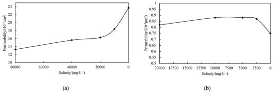
Figure 1.
Experimental results of water sensitivity damage evaluation of cores with different permeabilities. (a) Core No. 1 (116.81 mD). (b) Core No. 2 (5.30 mD).
The experimental results of evaluating the acid sensitivity damage of cores with different permeabilities are shown in Figure 2.
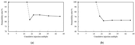
Figure 2.
Experimental results of the acid sensitivity damage evaluation of cores with different permeabilities. (a) Core No. 1 (16.70 mD). (b) Core No. 2 (101.20 mD).
2.2. Adaptive Analysis of Integrated Tubing String
The offshore Dongying formation Oilfield suffers from problems such as oil layer contamination and blockage of pore throats in the near-well area, which seriously affect the development effect and urgently require the implementation of acidification production enhancement measures [16,17,18,19,20,21]. The well-completion quality of the target oilfield is good, and the integrated technology of acidizing and fluid return is relatively time- and space-cost-saving, which can meet the requirements of the acidizing operation [22,23].
The main challenges encountered during the construction are as follows: the oilfield reservoirs have issues such as water sensitivity and acid sensitivity, which can lead to phenomena such as water lock, clay expansion, and reservoir blockage; the reservoirs are deep, and it is difficult to return the acid fluid and its acid–rock reaction derivatives into the well, especially when the drainage time is long [24,25,26,27,28].
3. Design and Mechanical Analysis of the Integrated Acidizing and Flowback Tubing String Model
3.1. Integrated Acidizing and Flowback Process Design
The offshore Dongying Formation reservoir exhibits sensitivity to velocity, water, and acid, leading to issues such as water blocking, clay swelling, and formation damage. Conventional completion strings further complicate post-acidizing flowback, resulting in prolonged cleanup times and significant wellhead backpressure [29]. For certain gas wells requiring post-perforation acidizing, additional steps such as well control and tubing replacement are necessary before pumping and flowback can proceed [30,31]. These repeated well interventions exacerbate formation damage and extend operational cycles, thereby increasing costs.
While acidizing can remove near-wellbore solids and soluble minerals to enhance permeability, it may also compromise rock integrity. Therefore, it is critical to optimize both the acidizing fluid system and operational procedures. A less-aggressive fluid with slower reaction kinetics should be selected to minimize damage to rock cementation. Furthermore, the efficient and thorough flowback of spent acid is essential to mitigate secondary formation damage [32,33].
3.1.1. Plan Concept and Expected Goals
- (1)
- Plan concept
The simplified diagram of the acidizing flowback integration process flow is shown in Figure 3 [34,35].
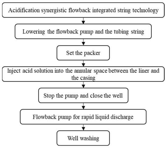
Figure 3.
Schematic diagram of the acidizing flowback integration process.
- (2)
- Expected goals
① A single tubing string can achieve acid fracturing for blockage removal, and rapid reaming, and enhance the effectiveness of acidizing operations.
② By using an integrated tubing string, costs can be reduced and efficiency increased, and economic and time costs can be lowered.
③ Optimizing the construction process can improve the safety of the operation and reduce operational risks.
3.1.2. Integrated Acidizing and Flowback Operation Construction Procedures
The detailed working process of acidizing and flowback tubing string is shown in Figure 4 [36,37,38,39].
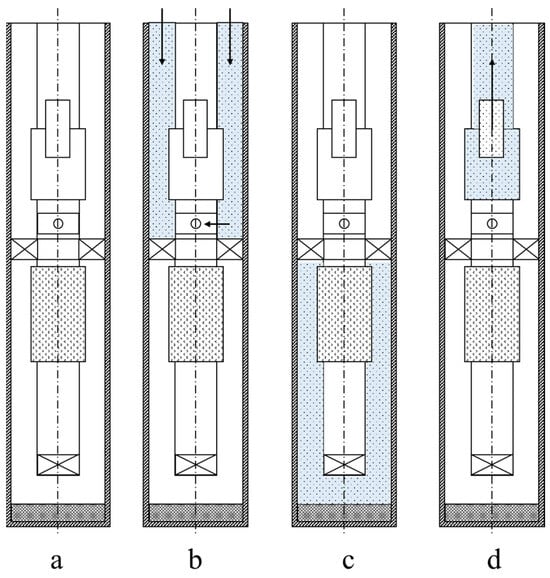
Figure 4.
Detailed operation flowchart of the integrated acidizing and flowback tubing string. (a) Lowering the tubing string and setting it in place. (b) Injecting acid into the well. (c) Acidic fluid dissolving blockages. (d) Returning the acid fluid for re-extraction.
3.2. Integrated Tubing Column Structure Model for Acidizing and Flowback Recovery
3.2.1. Casing Structure Design
The injection structure is realized by devices such as packers and backwash valves. The return and displacement structure mainly consists of sucker rods and return pumps, and the return process is accomplished by the sucker rods driving the return pumps to move up and down [25,26,27,30,31,32,33,39,40,41,42]. The overall structure of the acidizing and flowback integrated construction pipe column designed for this work is shown in Figure 5.
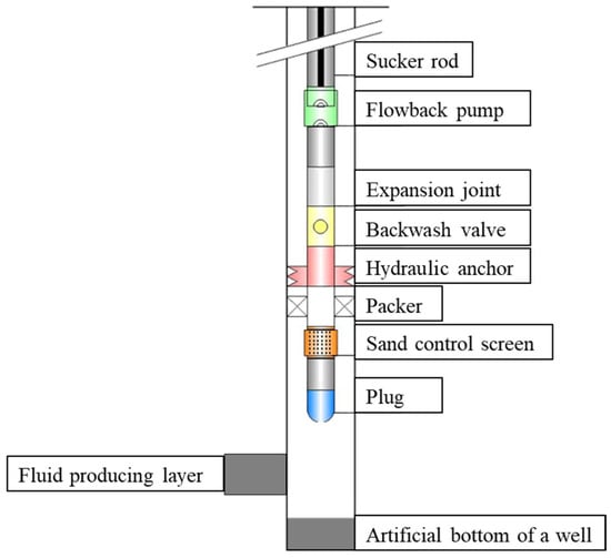
Figure 5.
Integrated tubing column structure model for acidizing and flowback operations.
3.2.2. Casing Selection Design and Calculation
Taking the 7-inch casing well size of the offshore Dongying formation Oilfield as the design basis, a set of methods and processes suitable for the matching of the downhole tubing string was designed, as shown in Figure 6 [37,43,44,45].
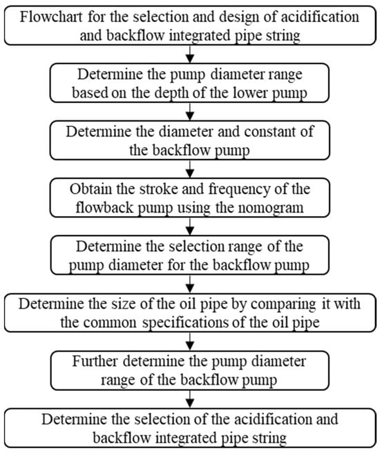
Figure 6.
Design flow chart for the selection of acidizing flowback integrated tubing string.
To meet the needs of acidizing tubing string backflow, as important equipment for backflow injected fluid, the first task is to clarify the available range of pump diameters for backflow pumps, calculate the theoretical discharge of the backflow pump, and the mathematical model used is as follows (1):
In the formula: Ap is the plunger area, m2; QT is the pump theoretical displacement, m3·d−1; K is the flowback pump constant, m2; N is the stroke rate of the pump, min−1; and S is stroke length, m.
The matching relationship among the pump diameter of the return pump, the piston area of the return pump, and the pump constant of the return pump are shown in Table 3. The nomogram for selecting the stroke and frequency of the return pump under different working conditions is shown in Figure 7.

Table 3.
Data sheet for pump diameter, plunger area, and pump constants of the return pump.
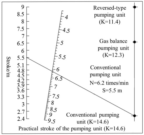
Figure 7.
Nomogram for selecting the stroke and frequency of the return pump under different operating conditions.
The No model diagram that matches the pumping stroke and stroke frequency commonly used in oilfield production operations is selected, and the stroke and stroke frequency values required for the return operation conditions are determined [46].
The relationship between the pump diameter of the return pump and the size of the sucker rod is shown in Table 4.

Table 4.
Matching table of pump diameter and sucker rod specification.
Based on the matching results of the pump diameter of the return pump and the specifications of the sucker rod, combined with the commonly used tubing specifications and sizes in actual production, the matching was carried out as shown in Table 5.

Table 5.
Specification and size of the oil pipe.
3.2.3. Main Components of the Acidification Pipe Column
- (1)
- Extension and retraction joint
The extension and retraction joint is mainly designed with a key slot structure, and its size is slightly larger than the inner diameter of the tubing. The extension and retraction joint generally compensates for the movement of the tubing during oil well acidizing and fracturing operations and is also convenient for adjusting the length at the wellhead [30].
- (2)
- Packer
As shown in Table 6, by comparing the technical parameters of the Y211 packer and RTTS packer, according to the requirements of the integrated tubing string, the RTTS packer can be applied in acidizing operations and can meet the reverse flushing conditions. Therefore, the RTTS packer is selected for the tubing string structure.

Table 6.
Technical parameters of packer (Y211 and RTTS).
- (3)
- Reverse flushing valve
The annular pressure reverse flushing valve is a reverse circulation valve that opens by relying on the annular pressure and can be spring-reset closed. It is commonly used in 7-inch casing wells and is mainly used for reverse circulation operations or for returning after acid fracturing.
- (4)
- Hydraulic anchor
The insertion of the sealing outer diameter is 101.6 mm, and the inner diameter of the plug-in opening tool is 47 mm. One hydraulic anchor is installed in the tubing string to anchor the tubing string and prevent the tubing string from moving upward during acidizing.
3.2.4. Basic Mechanical Effects of Downhole Pipe Column
During the acidizing and reverse circulation operation, the tubing string is mainly subjected to various loads such as buoyancy force, flow viscous effect, piston effect, bulging effect, temperature difference effect and helical bending effect [47,48].
- (1)
- Floating weight effect
The direction of the gravitational force acting on the acidizing operation tubing string is vertically downward. The gravitational force acting on each unit length of the operation tubing string is
In the formula, qoi is the gravitational distributed force acting on the target tubing string, N·m−1; Ao is the cross-sectional area of the target tubing string, m2; ρo is the density of the tubing string, kg·m−3; and g is the gravitational acceleration, m·s−2.
The buoyancy of the well fluid acting on the acidizing operation tubing column is perpendicular to the axis of the tubing column in the direction. The force distribution per unit length of the buoyancy is
In the formula, qoli represents the buoyancy distribution force of the target tubing string, N·m−1; ρl is the density of the liquid in the wellbore, kg·m−3; and θ is the angle between the axis of the tubing string and the horizontal plane, rad.
- (2)
- Viscous flow effect
During the process of being lowered into the well, the operation string will encounter frictional resistance from the fluids in the well. The direction of this resistance is parallel to the axis of the operation string and is opposite to the direction of the string’s movement during the lowering process. The distribution force of the frictional resistance is calculated using the following formula.
The distribution force of frictional resistance is
In the formula, qfr is the frictional distribution force between the operation tubing and the wellbore fluid, N·m−1; μL is the dynamic viscosity of the fluid in the annular space, mPa·s; m is the ratio of the inner diameter of the casing to the outer diameter of the tubing; Dr is the inner diameter of the casing, m; Dri is the inner diameter of the tubing, m; and vfp is the relative velocity of the wellbore fluid and the operation tubing, m·s−1.
The Reynolds number of the annular flow is
In the formula, Reo is the Reynolds number of the fluid in the annular space; vo is the average flow velocity of the fluid in the annular space, m·s−1; dw is the inner diameter of the casing, m; do is the outer diameter of the tubing, m; ρfo is the density of the fluid in the oil-tubing annular space, kg·m−3; μo is the viscosity of the fluid in the oil-tubing annular space, mPa·s; and Qo is the flow rate of the fluid in the oil-tubing annular space, m3·s−1.
If Reo ≤ 2000, the fluid is in a laminar flow state, and the total pressure of the fluid inside the annular space between the oil and casing is
In the formula, Po represents the total pressure of the fluids inside the annulus of the oil and casing in the well, MPa; and Po0 represents the total pressure of the fluids inside the annulus of the oil and casing at the wellhead, MPa.
If Reo > 2000, the fluid is in a turbulent state, and the total pressure of the fluid inside the annular space between the oil and casing is
- (3)
- Plunger effect
During the process of raising and lowering the pipe column, the packer connected to the pipe column moves in the wellbore fluid, resulting in inconsistent pressure on the upper and lower ends of the packer and generating axial loads. At this time, the working pipe column experiences the plunger effect. The schematic diagram of the piston effect is shown in Figure 8.
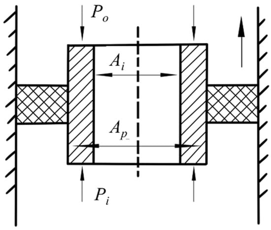
Figure 8.
The schematic diagram of the piston effect.
The forces acting on the piston from below upwards and from above downwards are, respectively,
Assuming that the packer exerts a negative force when subjected to tension and a positive force when subjected to pressure, then the piston force is
In the formula, Ai represents the inner cross-sectional area of the pipe column, m2; Ao represents the outer cross-sectional area of the pipe column, m2; Po represents the internal pressure of the pipe column, MPa; Pi represents the external pressure of the pipe column, MPa; and Ap1 represents the cross-sectional area of the sealing chamber of the packer, m2.
Based on Hooke’s law, calculate the extension and contraction amount of the pipe column caused by the piston effect:
In the formula, L represents the length of the pipe column, m; E is the elastic modulus, MPa; and Ap2 is the cross-sectional area of the pipe column, m2.
Due to the changes in the environment where the operation tubing is located, there are fluctuations in the internal and external pressures. When the internal and external pressures of the operation tubing change, it will cause a change in the piston force:
The deformation of the pipe column caused by the change in piston force is
- (4)
- Bulging effect
When the fluid pressures inside and outside the pipe column change, it will cause the pipe column to undergo deformation towards the inside or outside, which is known as the bulging effect. The schematic diagram of the bulging effect is shown in Figure 9.
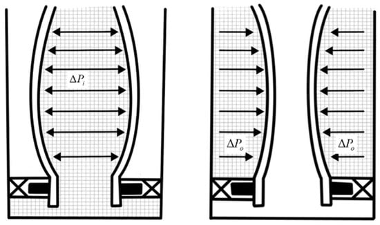
Figure 9.
The schematic diagram of the expansion effect.
The force generated by the bulging effect is
In the formula, ΔFe is the force caused by the bulging effect, kN; ΔPia is the average pressure change within the tubing string, MPa; and ΔPoa is the average pressure change within the annular space between the oil and casing, MPa.
The deformation caused by the bulging effect is
In the formula, μ represents the Poisson’s ratio of the material; R is the ratio of the outer diameter to the inner diameter of the tubing; Δρi is the change in the density of the fluid inside the tubing, kg·m−3; Δρo is the change in the density of the fluid inside the annular space, kg·m−3; ΔPis is the change in the pressure inside the tubing at the wellhead, MPa; ΔPos is the change in the pressure in the annular space at the wellhead, MPa; and δ is the pressure drop per unit length of the workover string caused by fluid flow, MPa·m−1.
- (5)
- Spiral bending effect
When the axial force at the position where the packer is located exceeds the critical force that causes the operation tubing string to undergo spiral bending deformation, and when the pressure change inside the tubing is less than the pressure change inside the annular space between the tubing and the casing, the tubing string will exhibit a spiral bending effect. The schematic diagram is shown in Figure 10.
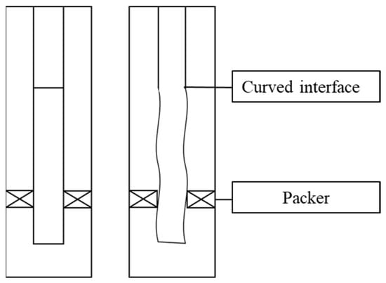
Figure 10.
The schematic diagram of the spiral bending effect.
The helical bending stress is
The spiral bending elongation and shortening amounts of the operation tubing column are as follows:
In the formula, ΔL1 represents the elongation of the tubing string due to bending, m; Ff is the effective bending force at the end of the tubing string, kN; EI is the bending stiffness of the tubing string; and r is the radius gap of the annular space between the tubing and casing, m.
By combining Equations (17) and (18), the axial deformation of the pipe column caused by the helical bending effect can be obtained as
- (6)
- Temperature effect
When the temperature changes, the working tubing string undergoes thermal expansion and contraction, and at this point, a temperature difference effect occurs in the tubing string.
The temperature effect results in the following force on the pipe column:
The temperature effect results in the column shape variable being
In the formula, α represents the temperature linear expansion coefficient of the tubing string, in units of °C−1; L denotes the length of the tubing string, m; ΔT represents the temperature gradient within the wellbore, °C·m−1; E is the elastic modulus of the tubing material, MPa; D is the outer diameter of the tubing string, m; and d is the inner diameter of the tubing string, m.
In particular, if the column-shaped variable is restricted by the packer, the following two phenomena will occur. When ΔT > 0, ΔLw > 0, the tubing string elongates and is subjected to axial compressive load; when ΔT < 0, ΔLw < 0, the tubing string shortens and is subjected to axial tensile load.
3.3. Study on the Force and Deformation of the Acidizing Tubing String Under Different Mechanical Effects
The acidizing operation tubing string is affected by factors such as buoyancy, gravity, and viscosity. At the same time, the existence of the piston effect, helical bending effect, bulging effect, temperature effect, and other basic effects, play a significant role in the force acting on the acidizing operation tubing string [36,41,42]. The force and deformation analysis of the acidizing tubing string is carried out, taking in and in as examples. The materials selected are common N80 and P105 steel grades, and the basic data are shown in Table 7.

Table 7.
Basic data of tubing.
- (1)
- Evaluation of the influence of buoyancy force on the acidizing operation tubing string
Taking the tubing string for the acidizing operation in a 3000 m oil well as an example, the in and in oil tubes were analyzed. The axial force and axial stress caused by the buoyancy force are shown in Figure 11. The axial force of the large-sized operation tubing string is smaller than that of the small-sized tubing string, and the tubing string with a larger wall thickness for acidizing operation experiences a greater axial force due to the buoyancy force. The deformation amount is related to the length of the tubing string. As the well depth increases, the deformation amount gradually increases, and the deformation trend gradually accelerates with the increase in tubing string length. At the same time, the deformation amount caused by the buoyancy force due to the floating weight of different diameters and different wall thickness tubing strings is very similar. The deformation amount caused by the buoyancy force of the 3000 m length tubing string is about 1.4 m.
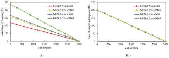
Figure 11.
Force diagram of the floating weight tubing string. (a) Axial force. (b) Axial stress.
- (2)
- Evaluation of the impact of the piston effect on the acidizing operation tubing string
The axial force and axial stress caused by the piston effect are shown in Figure 12. They are mainly related to the pressure difference between the inside and outside of the tubing string. Analysis reveals that as the pressure difference between the inside and outside of the tubing string increases, the axial force caused by the piston effect also increases. Moreover, when the pressure difference between the inside and outside of the tubing string is small, the axial force caused by the piston effect on the large-sized tubing string is greater than that on the small-sized tubing string. When the pressure difference is larger, the opposite effect occurs. Particularly, when the pressure difference between the inside and outside of the tubing string exceeds 15 MPa, the axial force on the small-sized tubing string exceeds that on the large-sized tubing string. It is analyzed that when the pressure difference between the inside and outside of the acidizing tubing string is small, the axial force caused by the piston effect has a more significant effect on the tubing string with a larger outer diameter. However, when the pressure difference exceeds a certain range, the tubing string with a smaller outer diameter experiences a more significant force [33,47]. The axial stress caused by the piston effect is related to the pressure difference in the acidizing tubing string. As the pressure difference increases, the axial stress also increases. At the same pressure difference, the stress on the larger-sized tubing string is relatively smaller, and the tubing string with a thicker wall thickness experiences a smaller stress.
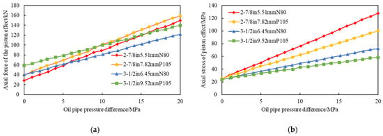
Figure 12.
Force diagram of the piston effect tube column. (a) Axial force. (b) Axial stress.
In addition, due to the tendency of the tubing string deformation caused by the piston effect to contract, the contraction deformation increases with the increase in tubing string length [31]. And when the well depth is the same, the larger the tubing string size, the smaller the deformation. The larger the wall thickness of the tubing string, the smaller the deformation.
- (3)
- Evaluation of the effect of bulging on the acidizing operation tubing string
The axial force caused by bulging is shown in Figure 13. The axial force has both positive and negative values. When the axial force is negative, it indicates that the internal pressure of the tubing string is less than the external pressure, and an internal bulging effect occurs, resulting in a reduction in the diameter of the tubing string. Conversely, when the axial force is positive, it indicates that the internal pressure of the tubing string is greater than the external pressure, and an external bulging effect occurs, resulting in an increase in the diameter of the tubing string. When the outer diameter of the tubing is the same, under certain conditions—when the pressure difference is small between the inside and outside of the tubing string, an internal bulging effect occurs, and the thicker-walled tubing string receives a relatively larger axial force. When the pressure difference is large, an external bulging effect occurs, and the thinner-walled tubing string receives a relatively larger axial force. Overall, the axial force on the large-sized tubing string is smaller than that on the small-sized tubing string. The stress on the tubing string of the same steel grade is relatively close. The influence is mainly related to the internal and external pressure differences. When the internal and external pressure differences in the tubing string are greater than 10 MPa, the stress received by the tubing string with a larger wall thickness is relatively smaller. The change in the tubing string shape due to the bulging effect is a contraction deformation. The deformation amount increases with the increase in well depth, and the overall deformation is less than 0.18 m. Therefore, the axial deformation of the tubing string caused by the bulging effect is relatively small.
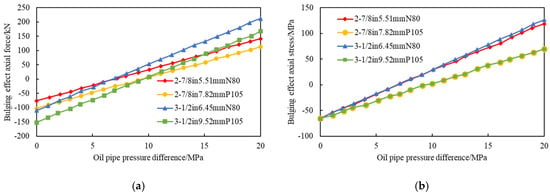
Figure 13.
Force diagram of the bulging effect pipe column. (a) Axial force. (b) Axial stress.
- (4)
- Evaluation of the effect of helical bending on the acidizing operation tubing string
When the axial force of the tubing string at the packer location exceeds the critical force that causes the tubing string to spiral bend, the tubing string will undergo spiral bending. The axial force that effectively acts on the end of the tubing string and causes the spiral bending effect is independent of the tubing string itself and is only related to the packer and the pressure difference between the inside and outside of the tubing string [46]. As shown in Figure 14, the axial stress caused by the spiral bending effect of different tubing strings due to the spiral bending effect and the change in the tubing string shape caused by bulging are calculated under different pressure differences. Analysis shows that under the same pressure difference conditions, the axial stress on the small-sized tubing string is relatively larger, and the axial stress on the tubing string with a smaller wall thickness is also larger.
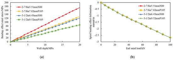
Figure 14.
Diagram of force and deformation of the spiral bending effect tube column. (a) Axial stress. (b) Deformation quantity.
The tubing string shape variable of 3000 m length increases with the increase in the end load. The negative values in the figure indicate that under the axial load at the end, the tubing string has a tendency to shorten in shape. Due to the fact that in actual production, the tubing string is not only affected by the end load but also by other factors such as self-weight and friction, the end axial load will not be so large, and the actual axial shape variable will be relatively lower than the calculated result.
- (5)
- Evaluation of the influence of the temperature effect on the acidizing operation tubing string
Due to the difference between the wellhead temperature and the temperature inside the well, the operation tubing string will be affected by the temperature, resulting in axial deformation. The magnitude of the axial stress caused by the temperature effect is only related to the formation temperature, the depth of the oil well, and the elastic modulus of the tubing string, and has no relation to the size of the tubing string [48]. The axial force variation in the tubing string caused by the temperature effect is shown in Figure 15. The axial force gradually increases with the increase in well depth, and larger-sized tubing strings are more affected by temperature. The tubing string deformation is mainly related to factors such as temperature and the expansion coefficient of steel and has little relation to the size of the tubing string. As the well depth increases, the deformation of the tubing string due to the temperature effect becomes more obvious and the trend becomes greater. The 3000 m operation tubing string deforms under the influence of the temperature effect, and its deformation is close to 1.8 m. The temperature has a very significant impact on the tubing string.
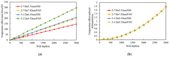
Figure 15.
Diagram of the force and deformation of the temperature effect tube column. (a) Axial stress. (b) Deformation quantity.
- (6)
- Evaluation of the influence of the flow viscosity effect on the tubing string in acidizing operations
The axial force and deformation of the tubing string caused by the flow viscosity effect are shown in Figure 16. As the well depth increases, the axial force gradually increases, and the larger the outer diameter of the tubing string, the smaller the axial force it receives. For the same-sized tubing string, the smaller the inner diameter, the greater the axial force it receives. For the same-sized tubing string, the stress is relatively close, but the stress received by the tubing string with a smaller inner diameter is relatively smaller, while the stress received by the tubing string with a smaller outer diameter is relatively larger. The flow viscosity effect has a significant impact on the deformation of the tubing string. Among them, the larger-sized tubing string undergoes deformation less than the smaller-sized tubing string. For the same-sized tubing string, the deformation is relatively close, and the tubing string with a larger inner diameter receives a greater influence than the tubing string with a smaller inner diameter.
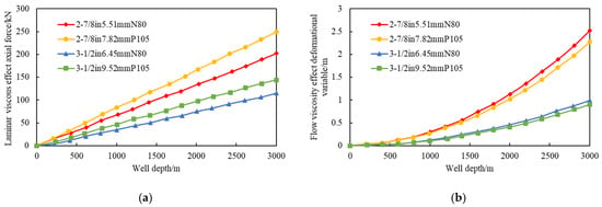
Figure 16.
Diagram of force and deformation of the flowing viscosity effect pipe column. (a) Axial stress. (b) Deformation quantity.
- (7)
- Analysis of total deformation of the tubing string caused by different effects
As shown in Figure 17, the deformation of the tubing string under the influence of different mechanical effects is calculated by superimposing, and the total deformation of the working tubing string is obtained. There are differences for pipes of different sizes. The deformation of the tubing string in an oil well at a depth of 3000 m is approximately 1.45 m.
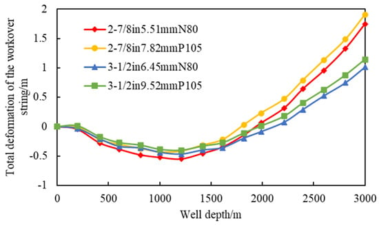
Figure 17.
Total deformation of the workover string.
4. Analysis of Key Equipment and Calculation of Force Distribution Simulation
4.1. Mechanical Analysis of Expansion Joints
Using the Fluent dynamic simulation software, the common working states of the expansion joint were simulated. Based on its safety, the simulation mainly focused on the tensile state when the pins were not broken and the entire tensile state when the pins were broken. The maximum stress that the expansion joint was subjected to was obtained through numerical simulation, and the maximum stress under different working conditions was calculated using the Lame formula, as shown in Table 8. By comparing the theoretical solution with the numerical solution, the results were similar, and the error between the two was controlled within 15%.

Table 8.
Theoretical solution of expansion joint strength under different working conditions.
4.2. Mechanical Analysis of Anti-Fouling Valve and Causes of Failure
The anti-washing valve, as a key tool for connecting the oil and casing, has its failure mainly caused by two aspects: sealing failure and mechanical faults.
- (1)
- Sealing Failure
The main seals of the anti-washing valve are O-ring seals and T-type seals. Affected by factors such as the fluid flow state through the valve, fluid pressure, and friction loss, the stress on the sealing rings will fluctuate continuously as the anti-washing valve operates [20,35]. Under this influence, failure is more likely to occur. Especially near the inlet, the T-type seals are subjected to fluid erosion for a long time, making the damage probability even greater.
- (2)
- Mechanical Faults
The fluid in the operation well has corrosiveness, and the equipment is in a high-temperature environment. The strength of the pins in the equipment has weakened. Moreover, in complex well conditions, the anti-washing valve equipment is constantly exposed to the fluid in the well with frequent pressure fluctuations. The frequent and complex changes in pressure may cause premature failure of the pins of the anti-washing valve. At the same time, affected by the environment, the spring used to close the anti-washing valve will have weakened elasticity, which may lead to a situation where the anti-washing valve cannot be closed tightly.
The design precision between the inner cylinder, outer cylinder, and the anti-washing valve is very high. Any problem in the cooperation, materials, sealing, and assembly quality of these parts may cause jamming and affect the normal operation of the anti-washing valve. Moreover, the downhole environment of the operation well is complex, and there is tool debris such as formation sand, pipe column fragments, pins, and other solid particles. During the operation of the anti-washing valve, solid particles entering the mechanical gap will also cause mechanical wear and jamming, and even damage the mechanical structure of the anti-washing valve.
4.3. Mechanical Analysis of Reverse Discharge Pump and Calculation of Displacement
Based on the geological characteristics of the offshore Dongying formation Oilfield and the requirements of the integrated acidizing and flowback tubing string technology, with a 7-inch wellhead size as the design basis, the theoretical displacement of the flow-back pump was calculated and analyzed. The basic parameter table for offshore flowback construction shown in Table 9 indicates that in actual production, to enhance the flowback effect, the stroke can be raised to 4–6 m.

Table 9.
Basic parameters of offshore flowback construction.
4.4. Dynamic Simulation of Stress and Deformation
A dynamic simulation and optimization software for pipe column mechanics was developed using the C#. By inputting basic data, the wellbore trajectory, the types of casing and pipe column structures, the pipe column dimensions, the relative density of the well entry fluid, and the downhole depths of the pipe column-related equipment can be constructed. Based on this, the software can conduct mechanical analysis of the pipe column under different working conditions. The data well for the target block is established based on the actual well inclination data of the target block. Numerical simulation is carried out using this software to construct a three-dimensional wellbore trajectory and pipe column structure model diagram. According to the information of the offshore Dongying formation reservoir, it is known that the burial depth of the oil layer in this area is within the range of 2596–3602 m. The acidification operation simulation of the target block is carried out, with the pipe columns at 2700 m, 3000 m, and 3300 m as the research objects. Three data wells that conform to the target block reservoir are established and numerical simulation is conducted using this software for mechanical analysis. The data for the wellbore trajectory is shown in Table 10. The results of the mechanical analysis and calculation for the oil well when the depths are 2700 m, 3000 m and 3300 m are shown in Figure 18, Figure 19 and Figure 20.

Table 10.
X oil well deviation part data.
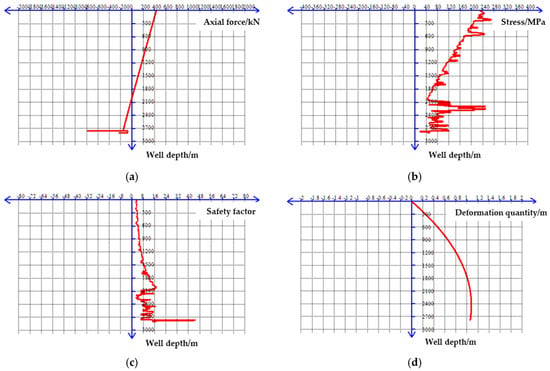
Figure 18.
Mechanical analysis of the acidizing operation process for a 2700 m tubing string. (a) Axial stress. (b) Stress. (c) Safety factor. (d) Deformation quantity.
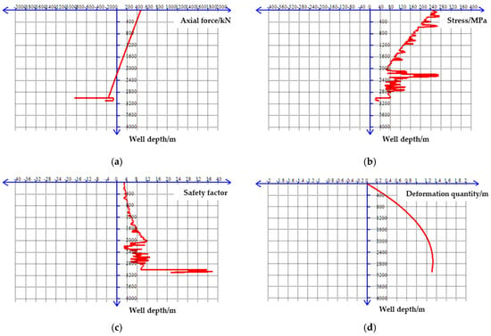
Figure 19.
Mechanical analysis of the acidizing operation process for a 3000 m tubing string. (a) Axial stress. (b) Stress. (c) Safety factor. (d) Deformation quantity.
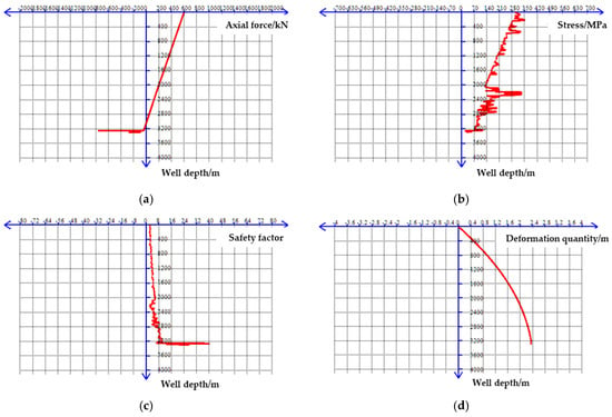
Figure 20.
Mechanical analysis of the acidizing operation process for a 3300 m tubing string. (a) Axial stress. (b) Stress. (c) Safety factor. (d) Deformation quantity.
It is known that the expansion joint compensation distance is 3 m. The individual maxima arise under different boundary conditions and do not occur at the same time. Through the dynamic simulation and calculation of the integrated tubing string for acidizing and flow-back in Section 3.3, the deformation of different operation tubing strings under different conditions was measured [32]. As shown in Figure 21, the deformation of the tubing string is within the safe range within the expansion tube compensation range. The maximum axial force of the 2700 m operation tubing string is approximately 400 kN, the maximum axial stress is approximately 260 MPa, the safety factor is greater than 3.0, and the maximum deformation of the tubing string is approximately 1.1 m. The maximum axial force of the 3000 m operation tubing string is approximately 500 kN, the maximum axial stress is 300 MPa, the safety factor is greater than 3.0, and the maximum deformation of the tubing string is approximately 1.4 m. Meanwhile, the maximum axial force of the 3300 m operation tubing string is approximately 600 kN, the maximum axial stress is 350 MPa, the safety factor is greater than 3.0, and the maximum deformation of the tubing string is approximately 2.4 m. During the operation, the tubing string is relatively safe.
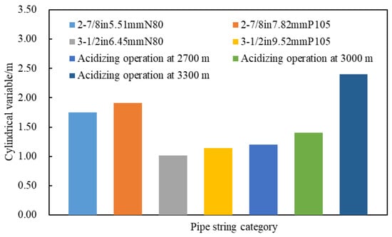
Figure 21.
Comparison chart of different operation pipe column shapes.
5. Evaluation of Production Increase Effect
5.1. Application Example
Based on on-site applications, the acidizing and flowback integrated process technology was tested, and its effect was analyzed [49,50,51,52]. Through comparative analysis, the economic and social effects of negative pressure flowback pump flowback compared with other flowback methods were compared. The comprehensive evaluation of the acidizing and flowback integrated process was improved. The application example well was the CBG-10 well in the offshore Dongying formation Oilfield. The total well depth was 3260.68 m, the maximum well inclination depth was 2448.46 m, the maximum well inclination angle was 23.30°, and the maximum well inclination azimuth was 238.43°. The casing of the operation well was 762 mm in specification, with a depth of 95.93 m. The surface casing specification was 339.7 mm, with a depth of 701.54 m. The technical casing specification was 177.8 mm, with a depth of 3226.68 m. The cementing quality was excellent. The pump injection volumes of the pre-acid pretreatment solution, the main acid plugging solution, and the post-active flushing acid are 15–20 m3. The construction displacement is ≤0.4 m3/min, and the injection method is to inject while closing the casing. The detailed casing data and cementing data are shown in Table 11.

Table 11.
Casing data and cementing data of the operation well.
The structure of the construction tubing string is as follows: plug + 2 strands of spiral screen pipe + 22 pieces of 89 mm EU oil tubes + safety joint + hydraulic anchor + RTTS packer + 1 piece of 89 mm EU oil tube + acid-resistant flowback pump + pin-type oil release device + 115 pieces of 89 mm EU oil tubes + stop valve + 1 piece of 89 mm EU oil tube + 2 pieces of 89 mm EU oil tubes + sanding movable elbow.
The construction effects before and after the acidizing operation of the target well were compared. Before the acidizing operation, the daily liquid production of the operation well was 50.5 t·d−1, and the daily oil production was 6.3 t·d−1. After the acidizing operation, the daily liquid production of the operation well was 150.9 t·d−1, and the daily oil production was 15.7 t·d−1. After the implementation of the acidizing operation, the daily liquid production capacity and the daily oil production capacity have been significantly improved, with the liquid production increasing by approximately 100 t·d−1 and the oil production increasing by approximately 10 t·d−1. The construction effects are shown in Table 12.

Table 12.
Construction effect after operation.
Before the acidizing and fluid return operation was carried out in other wells of the target block, the maximum daily liquid production was 89.0 t·d−1, the maximum daily oil production was 13.4 t·d−1, and the average daily liquid production of the 9 wells was 42.1 t·d−1, with an average daily oil production of 11.3 t·d−1. The comparison of liquid production before and after acidizing operations in other wells of the research area is shown in Figure 22. After the acidizing and fluid return operation, the maximum daily liquid production was 164.2 t·d−1, the maximum daily oil production was 54.1 t·d−1, the average daily liquid production of the 9 wells was 89.4 t·d−1, and the average daily oil production was 29.4 t·d−1. Among them, the maximum increase in daily liquid production per well exceeded 150.0 t·d−1, the maximum increase in daily oil production exceeded 45.0 t·d−1, the average daily liquid production increased by 47.3 t·d−1, and the daily oil production increased by 18.07 t·d−1.
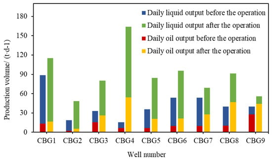
Figure 22.
Comparison of fluid production before and after acidizing operations in other wells.
5.2. Economic and Social Impact Evaluation
Using the negative pressure return flow of the return pump to reduce costs can save more than CNY 500,000 compared to the other two processes; it can also save more than 40% of construction time. The comparison for the construction of different backflow operation methods is shown in Table 13. The negative pressure return flow of the return pump can eliminate the need for ship support, and the acidification return fluid can be incorporated into the pipeline, significantly reducing the operational risks of the construction and alleviating the environmental pressure of offshore operations. Through multiple safety auxiliary devices, the safety risk points are relatively low.

Table 13.
Comparison table for the construction of different backflow operation methods.
6. Conclusions
- (1)
- An innovative integrated process of acidizing-flowback was achieved by injecting acid through the tubing-casing annulus and conducting acidizing via the reverse flushing valve in the target zone, combined with the rapid flowback of spent acid using a return pump. This approach reduces time and space costs while effectively preventing secondary formation damage.
- (2)
- The tubing string is primarily subjected to mechanical effects, including buoyancy, piston effect, flow viscosity effect, helical buckling, temperature differential effect, and ballooning effect. The maximum deformations are 1.4 m, 1.9 m, 0.18 m, 2.7 m, 1.8 m, and 2.5 m, respectively, all remaining below 3 m, indicating overall string safety.
- (3)
- Dynamic simulation and optimization software for tubing string mechanics, developed in C#, was used to simulate three groups of wells at different depths. Results showed axial forces of 400–600 kN, stress of 260–350 MPa, deformation of 1.1–2.4 m, and safety factors exceeding 3.0, confirming operational safety.
- (4)
- Field application demonstrated significant production enhancement, with example wells showing an approximately 100 t·d−1 increase in total fluid production and about a 10 t·d−1 increase in oil production. The integrated acidizing flowback technology achieved economic savings exceeding CNY 500,000, reduced time costs by over 40%, and effectively ensured operational safety.
Author Contributions
Conceptualization, L.W. and J.W.; methodology, Y.C. and M.S.; software, Y.C.; validation, T.W. and J.W.; formal analysis, T.W.; investigation, Y.C.; data curation, T.W.; writing—original draft preparation, L.W. and M.S.; writing—review and editing, M.S. and T.W. All authors have read and agreed to the published version of the manuscript.
Funding
This research was funded by the Lanzhou City University Doctoral Research Fund Project (LZCU-BS2025-10), and the National Natural Science Foundation of China (42202182).
Data Availability Statement
Data are contained within the article.
Acknowledgments
The authors would like to extend their heartfelt thanks to Lanzhou City University, China University of Petroleum (East China) and Yangtze University for the invaluable educational foundation and academic support that have significantly contributed to the development of this work, and express their sincere gratitude to PipeChina Engineering Technology Innovation Co., Ltd. for materials support and for providing access to laboratory facilities that were essential for the successful completion of this study. Additionally, the authors also express their sincere appreciation to the anonymous reviewers for their valuable and constructive comments.
Conflicts of Interest
Author Yi Chen was employed by the company PipeChina Engineering Technology Innovation Co., Ltd. The remaining authors declare that the research was conducted in the absence of any commercial or financial relationships that could be construed as a potential conflict of interest.
References
- Al-Shargabi, M.; Davoodi, S.; Wood, D.A.; Ali, M.; Rukavishnikov, V.S.; Minaev, K.M. A critical review of self-diverting acid treatments applied to carbonate oil and gas reservoirs. Petrol. Sci. 2023, 2, 922–950. [Google Scholar] [CrossRef]
- Cai, J.; Yang, J.; Huang, Z.; Xu, S.; Zhang, L.; Wang, H. Quantitative evaluation of residual acid invasion and flowback in fractured-vuggy carbonate reservoirs using microfluidics. Energies 2025, 18, 1162. [Google Scholar] [CrossRef]
- Zhang, J.; He, J.; Zhang, R.; Zhang, L.; Xu, W. Optimization and performance evaluation of an atomized acid system for the expansion of carbonate gas injection. Processes 2023, 11, 3080. [Google Scholar] [CrossRef]
- Jafarpour, H.; Moghadasi, J.; Khormali, A.; Petrakov, D.; Ashena, R. Increasing the stimulation efficiency of heterogeneous carbonate reservoirs by developing a multi-bached acid system. J. Pet. Sci. Eng. 2019, 172, 50–59. [Google Scholar] [CrossRef]
- Hu, J.; Liu, H.; Wu, D.; Zhang, J. Acidizing flowback optimization for tight sandstone gas reservoirs. J. Nat. Gas. Sci. Eng. 2015, 24, 311–316. [Google Scholar] [CrossRef]
- Nasriani, H.R.; Jamiolahmady, M. Optimising flowback strategies in unconventional reservoirs: The critical role of capillary forces and fluid dynamics. Energies 2024, 17, 5822. [Google Scholar] [CrossRef]
- Zhang, W.; Gao, D.; Liu, Y.; Bai, J.; Wang, C. Study of the failure mechanism of an integrated injection-production string in thermal recovery wells for heavy oil. Energies 2023, 16, 3246. [Google Scholar] [CrossRef]
- Saini, R.K.; Sayed, M.A.; Cairns, A.J. Flowback additive for acidizing fluid to stimulate carbonate gas reservoirs. Soc. Pet. Eng. J. 2024, 29, 4841–4855. [Google Scholar] [CrossRef]
- Wang, Y.; Zhou, F.; Su, H.; Li, Y.; Yu, F.; Dong, R.; Wang, Q.; Li, J. Performance evaluation of microemulsion acid for integrated acid fracturing in Middle Eastern carbonate reservoirs. Petrol. Explor. Dev 2023, 50, 1196–1205. [Google Scholar] [CrossRef]
- Ren, J.; Liu, Z.; Deng, Y.; Guo, J.; Lai, J.; Wang, J.; He, S. The quantitative study of residual acid damage of low permeability carbonate rock based on NMR test. Geoenergy. Sci. Eng. 2024, 241, 213109. [Google Scholar] [CrossRef]
- Li, P.; Wang, L.; Lai, X.; Gao, J.; Dang, Z.; Wang, R.; Mao, F.; Li, Y.; Jia, G. Two-level self-thickening mechanism of a novel acid thickener with a hydrophobic-associated structure during high-temperature acidification processes. Polymers 2024, 16, 679. [Google Scholar] [CrossRef]
- Cai, W.; Huang, Z.; Mo, X.; Zhang, H. Velocity string drainage technology for horizontal gas wells in Changbei. Processes 2022, 10, 2640. [Google Scholar] [CrossRef]
- Zhang, L.P.; Zhang, L.; Lan, X.T.; Liu, C.L.; Zou, J.; Gao, S. Application of non-acid block removing technology in Bohai Oilfield. Drill. Fluid Complet. Fluid 2018, 35, 116–122. [Google Scholar]
- Yuan, H.; Sun, Y.; Xiong, W.; Niu, W.; Tang, Z.; Li, Y. Advances in evaluation methods for artificial fracture networks in shale gas horizontal wells. Appl. Sci. 2025, 15, 9008. [Google Scholar] [CrossRef]
- Chen, D.; Sun, Z. Gas–liquid flow pattern and hydrate risk in wellbore during the deep-water gas-well cleanup process. ACS Omega 2023, 8, 12911–12921. [Google Scholar] [CrossRef] [PubMed]
- Liu, J.W.; Xian, G.Q.; Li, C.Y.; Qu, H.M.; Tan, Y.X.; Cui, Y.H.; Ding, Z.F.; Xiao, H.; Zhao, T.H. Acidizing, Negative-Pressure and Flowback Integrated Equipment and Technology. CN Patent CN105672976, 15 June 2016. Available online: https://ss.zhizhen.com/detail_38502727e7500f261a7b5f441dec441545103c5d99a9155e1921b0a3ea25510133e7f87ae1903bd62163d3a8b505c2ddfc7d188a48f9f2e7424194cada808d01a613e5dd08e158c2f826a6a8f4e512e2? (accessed on 1 November 2025).
- Lin, C.; Kang, Y.; He, H.; Han, L.; Xu, Q.; Li, G.; Zhou, H. Geoscience-engineering integration-based formation damage control drill-in fluid (GEI-FDC-DIF): An essential technology for successful extraction of deep mid-high permeability sandstone reservoirs. Geoenergy Sci. Eng. 2024, 237, 212828. [Google Scholar] [CrossRef]
- Wang, C.; Zhang, J.; Huang, B.; Du, H.; Meng, X.; Li, X.; Xue, X.; Su, Y.; Li, C.; Guo, H. Polymer flooding injectivity maintaining and enhancement strategies: A field case study of chinese offshore EOR project. Processes 2025, 13, 903. [Google Scholar] [CrossRef]
- Wu, S.W.; Zhou, H.Y.; Lin, K.X.; Yuan, H.; Luo, G.; Hu, Y.L. An integrated working fluid for blocking removal and sand control in offshore wells blocked by particle migration. Drill. Fluid Complet. Fluid 2021, 38, 391–396. [Google Scholar]
- Ming, E.; Li, C.; Lan, H.; Yu, J.; Zheng, L.; Pei, X. Modelling wave transmission for transient flow and amplitude-frequency characteristics of tubular string in a water injection well. Appl. Sci. 2023, 13, 3917. [Google Scholar] [CrossRef]
- Li, D.; Gao, B.; Cui, X. Emulsifying behavior between oil and water of flowback fluids from acidizing oil wells based on high-voltage electric field oil–water separation technology. New J. Chem. 2022, 46, 16858–16873. [Google Scholar] [CrossRef]
- Li, S.N.; Yan, W. Commonly used treatment technology of acidizing fluid flowback. Open J. Nat. Sci. 2017, 5, 302–305. [Google Scholar] [CrossRef]
- Zhai, Z.B.; Qi, S.W.; Kartoatmodjo, G. Pressure survey, analysis and diagnostic of small diameter velocity string to improve well monitoring and surveillance. Pet. Sci. Technol. 2022, 41, 1019–1037. [Google Scholar] [CrossRef]
- Yin, D.; Luo, P.; Zhang, J.; Yao, X.; Wang, R.; Wang, L.; Wang, S. Synthesis of oligomeric silicone surfactant and its interfacial properties. Appl. Sci. 2019, 9, 497. [Google Scholar] [CrossRef]
- Kong, X.; Liu, B.; Xu, H.; Shen, J.; Li, S. Optimization and performance evaluation of foam acid systems for plugging removal in low pressure oil and gas reservoirs. Processes 2023, 11, 649. [Google Scholar] [CrossRef]
- Li, J.T.; Han, J.J.; Xu, Q.H.; Xue, X.C.; Zhang, S.A. Third-Section Acid Pickling Integrated Well Completion Pipe String and Method. CN Patent CN105041267, 11 November 2015. [Google Scholar]
- Yu, Z.S.L. Perforating, Detecting, Acidating and Liquid-Discharging Integrated Testing Pipe String. CN Patent CNU2005201062073, 18 July 2007. Available online: https://ss.zhizhen.com/detail_38502727e7500f263168c25d27cffd2178ea8fa7e004e9451921b0a3ea25510133e7f87ae1903bd60cbc8308fe832728c7f667a6b29a344ca9480c637d9474d22eb13cf9a5c1052d6fd5fc3f93bf62bf? (accessed on 1 November 2025).
- Li, Q.Z.; Xu, D.K.; Wu, E.C. Deep Gas Well Subsection Acidizing and Completion Integral Tool String. CN Patent CNU2007201516785, 23 April 2008. Available online: https://ss.zhizhen.com/detail_38502727e7500f261a3b92c20e49cd472bc66bc1e2315ea81921b0a3ea25510133e7f87ae1903bd674cd55a89d1ef7a51c317007611b90ac4abc1a683a53ee43d75c28f4a098b629af4f8e85cdc5fa72? (accessed on 1 November 2025).
- Deng, S.; Li, X.; Yang, Z.; Yi, L.; Rao, D. Flow and heat transfer for non-Newtonian CO2 mixed fluid injection in the wellbore. Fuel 2025, 381, 133647. [Google Scholar] [CrossRef]
- Zhang, F.; Yang, X.; Peng, J.; Li, N.; Lv, S.; Zeng, N.; Zhang, R. Well Integrality technical practice of ultra deep ultrahigh pressure well in Tarim Oilfield. In Proceedings of the 6th International Petroleum Technology Conference, Beijing, China, 26–28 March 2013. [Google Scholar]
- Shishlyannikov, D.; Zverev, V.; Ivanchenko, A.; Zvonarev, I. Increasing the time between failures of electric submersible pumps for oil production with high content of mechanical impurities. Appl. Sci. 2022, 12, 64. [Google Scholar] [CrossRef]
- Li, J.; Ding, Y.Y.; Wang, L.R.; Shi, S.Z.; Liao, R.Q.; Zhang, M.L.; Zhang, Q. The mechanic analysis of integrated tubing string for acid fracturing and production. J. Oil Gas Technol. 2017, 39, 79–88. [Google Scholar] [CrossRef]
- Awotiku, O.; Hackney, D.; Ledergerber, A.; Ugah, I.; Femi-Saliu, B. Well clean out and acidization of a deepwater intelligent completion well—A case history. In Proceedings of the Nigeria Annual International Conference and Exhibition, Lagos, Nigeria, 1 July–2 August 2017. [Google Scholar]
- Wang, J.; Li, D.; Du, X.; Li, H.; Yang, S. Development of a design method for casing and tubing strings under complex alternating loads. Processes 2023, 11, 2582. [Google Scholar] [CrossRef]
- Al Ramadan, M.; Salehi, S.; Ezeakacha, C.; Teodoriu, C. Analytical and experimental investigation of the critical length in casing–liner overlap. Sustainability 2019, 11, 6861. [Google Scholar] [CrossRef]
- Feng, Z.; Guo, B.; Cai, Z.; Yuan, H. Eccentric wear mechanism and centralizer layout design in 3D curved wellbores. Appl. Sci. 2025, 15, 1494. [Google Scholar] [CrossRef]
- Li, Y.K.; Jia, Y.Y.; Zhang, G.Z.; Wang, H.W.; Cui, Y.H. Research progress and development suggestion of stratified acidizing strings in water injection wells of Shengli Oilfield. Pet. Drill. Tech. 2021, 49, 129–134. [Google Scholar]
- Zhao, X.; Geng, Q.; Qiu, Z.S.; Geng, T.; Zhou, G.W.; Xing, X.J. Gel-breaHng free drill-in nuid technology for deepwater high-porosity and high-permeability reservoirs. Nat. Gas Ind. 2021, 41, 107–114. [Google Scholar]
- Wang, Q.; Yang, H.; Han, X.; Huang, X.; Zeng, J.; Chen, W.; Zhang, H.; Li, L.; Zhou, C.; Wang, H. Method for Acid Fracturing Comprises e.g. Sandblasting and Perforating to Form Perforation Channel in Formation, Running Acid Fracturing String Into Wellbore, Injecting Acid Liquid into Perforation Channel, and Liquid Passes Through Perforation Channel to form Fractures in Formation. CN Patent CN10431573, 21 October 2022. Available online: https://ss.zhizhen.com/detail_38502727e7500f26a94cc9e8088d1781fbd65685d76678fe1921b0a3ea25510133e7f87ae1903bd6b466ec2028a731074210bf2a3c9923bf3bab857c045c8b9b3070a6704eede4aafe61327bf5125744? (accessed on 1 November 2025).
- Dore, F.P.; Pereira, A.Z.I.; Germino, F.D.S.M.; Ferreira, D.S.M.G.; Ignacio, P.A.Z.; Fernandes, P.D. Uniformization of Flow for Stimulation Operations Involves Using the Wash Pipe Tool to Stimulate the Reservoir, and Performing Reservoir Stimulation with the Wash Pipe Tool with Divergent Perforation During the Well Completion. US Patent US983606, 11 May 2023. Available online: https://ss.zhizhen.com/d-tail_38502727e7500f269f46c8a6849ffd8f01cd3ee1b951b0441921b0a3ea25510133e7f87ae1903bd6653e84ab8524ea2a70e511d2dca4593b77b7c8986150a9f2a384695c6c9a9b7f36834484f53973e0? (accessed on 1 November 2025).
- Pan, W.H.; Qian, Y.C.; Tao, J.Q.; Pan, Y.; Gu, S.B.; Wang, H. Application of original production string acidizing technology in oil well. Shiyou Huagong Yingyong 2013, 32, 7–11. [Google Scholar] [CrossRef]
- Yu, Y.; Cao, Y.; Qu, Z.; Dou, Y.; Wang, Z. Finite-element analysis on energy dissipation and sealability of premium connections under dynamic loads. Processes 2023, 11, 1927. [Google Scholar] [CrossRef]
- Martin, F.; Miquilena, E.; Molero, N.J.; Acevo, A.K.; Franco, E.; Garcia, M.G.; Castillo, M. Corrosion inhibition workflow allows injection of high-volume acid treatments through coiled tubing Strings in Offshore Mexico. In Proceedings of the International Conference and Exhibition on Oilfield Corrosion, Aberdeen, UK, 9–10 May 2012. [Google Scholar]
- Wang, Y.; Yang, J.; Zhang, Y.; Huo, L.; Song, Z.; Cao, X. Development and application of integrated injection system for injection and profile control in Dagang Oilfield. J. Phys. Conf. Ser. 2024, 2834, 012044. [Google Scholar] [CrossRef]
- Wang, J.; Xiong, Y.; Lu, Z.; Shi, J.; Wu, J. Influence of volume fracturing on casing stress in horizontal wells. Energies 2021, 14, 2057. [Google Scholar] [CrossRef]
- Cheatham, J.B.; Patillo, P.D. Helical postbuckling configuration of a weightless column under the action of m axial load. Soc. Pet. Eng. J. 1984, 24, 467–472. [Google Scholar] [CrossRef]
- Kyriakides, S.; Corona, E. Mechanics of Offshore Pipelines, Vol. 1: Buckling and Collapse; Gulf Professional Publishing: Houston, TX, USA, 2023. [Google Scholar]
- Lu, Y.P.; Wu, X.D.; Guo, S.S.; Fu, H.; Zhang, G.Y. Tubing string stress and axial deformation in gas wells. Nat. Gas Ind. 2008, 28, 100–102. [Google Scholar]
- Wang, C. Integrated technology for layered sand control and layered water injection. J. Phys. Conf. Ser. 2024, 2683, 012044. [Google Scholar] [CrossRef]
- Zou, J.; Huang, L.P.; Zhao, P.; Yang, M.; Gao, S. Analysis of the content of solid suspended matter in acid fracturing flowback fluids from oil wells in Bohai Oilfield. Drill. Fluid Complet. Fluid 2020, 37, 536–540. [Google Scholar] [CrossRef]
- Xu, B.; Chen, H.; Yin, G.; Qin, R.; Gao, J.; He, X. Acoustic transmission characteristics and model prediction of upper and lower completion pipe strings for test production of natural gas hydrate. Appl. Sci. 2025, 15, 9174. [Google Scholar] [CrossRef]
- Bai, Y.J.; Huang, B.; Zou, C.; Xu, X.N.; Liu, W.B.; Wang, Z.; Zhang, N.; Li, D.; Cao, G.S.; Fu, C. Mechanism of enhanced oil recovery by nanoparticles extracted from flowback fluids of acidizing oil wells. Colloid Surf. A 2024, 690, 133782. [Google Scholar]
Disclaimer/Publisher’s Note: The statements, opinions and data contained in all publications are solely those of the individual author(s) and contributor(s) and not of MDPI and/or the editor(s). MDPI and/or the editor(s) disclaim responsibility for any injury to people or property resulting from any ideas, methods, instructions or products referred to in the content. |
© 2025 by the authors. Licensee MDPI, Basel, Switzerland. This article is an open access article distributed under the terms and conditions of the Creative Commons Attribution (CC BY) license (https://creativecommons.org/licenses/by/4.0/).