Abstract
The rising demand for electric vehicles (EVs) has driven a significant increase in nickel consumption, a critical element in EV battery production. An industrially viable hydrometallurgical process was developed for the selective recovery of nickel from a copper-rich industrial intermediate, containing approximately 70 wt.% Cu and 6 wt.% Ni, predominantly as sulfides alongside minor impurities. Approximately 90% of nickel was selectively extracted via single-stage atmospheric pressure leaching using HCl and H2O2 at 95 °C for 12 h, with the majority of copper retained in the leach residue, which can be utilized as a valuable feedstock for copper smelters. The selectivity of nickel over copper was analyzed in detail through corresponding Pourbaix diagrams, and an appropriate leaching mechanism was proposed. The leachate was subsequently purified through a sequence of cementation, selective precipitation, and solvent extraction steps to remove residual copper, iron, and cobalt, achieving an overall separation efficiency of 99% with nickel losses below 2%. In the final stage, nickel carbonate was precipitated with >99% purity using sodium carbonate, potentially suitable for battery applications. The optimal conditions at each stage were determined through batch-type laboratory-scale experiments, which may need to be verified by continuous pilot-scale testing in the future. This process offers dual advantages by meeting the growing nickel demand for battery applications while simultaneously providing additional copper feedstocks for smelters.
1. Introduction
Nickel (Ni) products are typically categorized into two classes based on purity and application: class 1 and class 2. Class 1 Ni, containing over 99.8% nickel, is primarily demanded in advanced applications such as electric vehicle (EV) batteries and high-performance alloys. Conversely, class 2 Ni products, which include nickel pig iron (NPI) and ferronickel with purities below 99.8%, are mainly used in stainless steel manufacturing [1,2,3].
The recent surge in electric vehicle adoption has led to a rapid increase in class 1 Ni production, driven by the need for high-purity Ni compounds that enable batteries with enhanced energy density and longer lifespan at competitive costs [4,5]. These nickel compounds are predominantly sourced from three categories: primary raw materials like sulfide and laterite ores; intermediate forms such as mixed hydroxide precipitates (MHP), mixed sulfide precipitates (MSP), and Ni mattes; and secondary sources derived from recycled battery materials [6,7,8].
Sulfides and laterites are the two types of ores from which nickel is primarily sourced. Approximately 30–40% of land-based nickel resources are found in sulfide deposits, with the remainder in laterites [9,10]. Major sulfide deposits are located in Australia, Canada, Russia, and Southern Africa. Although laterites are more abundant, nickel production has historically favored sulfide ores due to their greater amenability to beneficiation, simpler processing and lower overall production costs [10,11]. Sulfide ores, such as pentlandite (Ni,Fe)9S8, are commonly found in specific geological settings and are characterized by their relatively high nickel content, often ranging from 1 to 3% nickel by weight. The extraction process commonly used involves froth flotation to produce a concentrate, followed by smelting, which produces a matte that is refined in converters to generate a product containing nickel along with copper and other sulfide minerals, which is further refined using hydrometallurgical and pyrometallurgical processes to recover the nickel and other valuable metals where necessary [12,13,14] as illustrated in Figure 1.
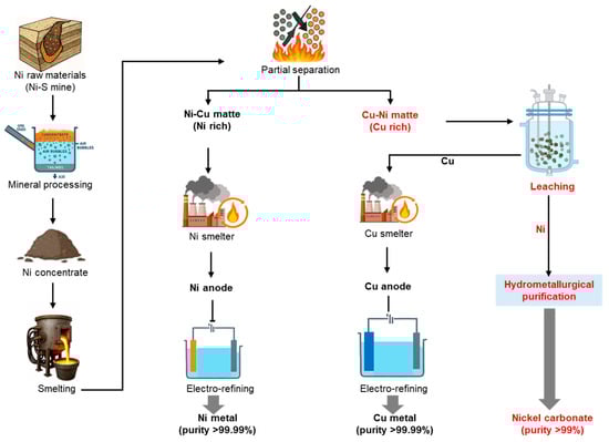
Figure 1.
Typical metallurgical route for Cu-Ni matte generation.
Several hydrometallurgical and pyrometallurgical techniques have been developed to extract nickel from nickel mattes, which typically contain elevated nickel concentrations of approximately 70–80%, with fewer impurities. These intermediates are relatively easier to process on a commercial scale to refine the nickel value. However, intermediates containing substantial quantities of other valuable metals, such as copper, but with lower nickel content, remain underutilized in nickel recovery processes. Table 1 provides a summary of the key challenges associated with nickel recovery from such low-grade nickel mattes (LGNM), where the nickel content is less than approximately 10%.

Table 1.
Summary of technologies applied in LGNM processing and their associated challenges.
As summarized in Table 1, current processing technologies for LGNM face several critical challenges. These include high capital expenditure (CAPEX) associated with high-pressure leaching, significant energy consumption due to high-temperature thermal treatments, difficulties in iron removal when using ferric chloride leaching, environmental risks linked to ammonia handling, and poor selectivity for nickel over copper and iron in many conventional methods. Therefore, there is a strong need to develop simple, selective, and cost-effective processes for nickel recovery from mattes with low nickel content.
One promising but underutilized strategy involves integrating nickel recovery processes into existing metallurgical infrastructure, particularly copper smelting operations. Such integration could expand feedstock flexibility for copper producers while simultaneously alleviating supply chain constraints in the battery materials sector.
In this study, we proposed and evaluated an industrially viable and economically attractive hydrometallurgical process for the selective recovery of nickel from a low-grade nickel matte (LGNM), which is rich in copper and contains low levels of nickel. This material is generated during nickel sulfide ore processing operations in Russia. As illustrated in Figure 1, two types of nickel mattes can be produced: (1) nickel-rich Ni-Cu matte, which is typically used to produce nickel cathode after undergoing pyrometallurgical purification, and (2) copper-rich Cu-Ni matte, which is more challenging to process at the same smelter and is therefore exported to copper smelters as a feed material [25,26]. However, since the Cu-Ni matte still contains valuable nickel, it is more cost-effective to recover the nickel content before processing directly in copper smelters. Our approach focused on the selective extraction of nickel from Cu-Ni matte produced by a nickel sulfide concentrate smelter in Russia, prior to its direct use as a secondary copper source in a South Korean copper smelter. The proposed process consists of three main stages: (1) selective nickel leaching by single-stage atmospheric pressure leaching; (2) purification steps, including copper removal via cementation, iron elimination through selective hydroxide precipitation, and cobalt separation using solvent extraction; and (3) production of high-purity nickel carbonate, potentially suitable for precursor materials for battery manufacturing. This hydrometallurgical process offers dual benefits: it enables copper smelters to enter the nickel value chain and expands the flexibility of their copper feedstock sources.
2. Experimental
2.1. Materials
The feed material, Cu-Ni matte specimens, used in this study were obtained from a nickel smelting operation in Russia, where nickel sulfide was the primary feedstock. The particle size of the Cu-Ni matte was within the range of 50–150 µm, and it is a fine black powder-like material. The samples contained approximately 70 wt.% copper and 6 wt.% nickel, along with trace amounts of impurities such as iron and cobalt. The detailed chemical composition of the Cu-Ni matte is summarized in Table 2. Metal concentrations were analyzed by using inductively coupled plasma optical emission spectroscopy (ICP-OES, Agilent 5800, Agilent Technology, Santa Clara, CA, USA) after digestion of the feed material. Total sulfur was calculated as the sum of elemental sulfur and sulfur present in sulfide minerals. Elemental sulfur content was determined using a carbon/sulfur analyzer (HORIBA EMIA), and the sulfur present as sulfide minerals was estimated based on the identified crystalline phases of the key elements. X-ray diffraction (XRD) analysis, shown in Figure 2, identified the crystalline phases present within the matte. Nickel was predominantly found as Ni3S2, while copper existed in both Cu1.8S and CuO forms. Moreover, quantitative Rietveld analysis of the XRD patterns revealed that approximately 10% of the total copper exists as CuO, while the remaining portion is present as Cu1.8S.
Table 2.
Chemical composition of the Cu–Ni matte determined by ICP-OES and carbon/sulfur analyzer.
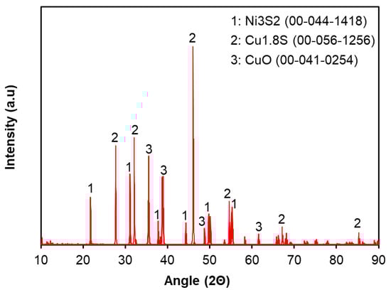
Figure 2.
X-ray diffraction patterns of the Cu-Ni matte used in this study.
Due to the low solubility of nickel sulfide under atmospheric acid leaching conditions [27], hydrochloric acid leaching supplemented with H2O2 as an oxidizing agent was employed in this study. When selecting the types of chemicals for developing this process, their industrial-scale availability for future commercialization was also considered. In our laboratory tests, all chemicals used in the experimental procedures, including hydrochloric acid (HCl, 37 wt.%, Sigma-Aldrich, Taufkirchen, Germany), hydrogen peroxide (H2O2, 35 wt.% stock solution, Merck, Darmstadt, Germany), Cyanex 272 (≥95%, Sigma-Aldrich), Kerosene (0.8 g/mL at 25 °C (lit.), Sigma-Aldrich) as diluent, sodium carbonate (Na2CO3, ≥99%, Merck), sodium hydrosulfide (NaHS, ≥98%, Sigma-Aldrich), and sodium hydroxide (NaOH, ≥98%, Sigma-Aldrich), were used as received. Iron scraps used in the cementation experiments were obtained from a metal scrap recycling company, with a purity greater than 98%.
2.2. Methodology
Optimal conditions for selective leaching, cementation, selective precipitation, solvent extraction, and carbonate precipitation were determined experimentally by systematically varying the relevant parameters. The experimental conditions and all key parameters are summarized in Table 3. All experiments were conducted in triplicate (n = 3), and the error bars in the result graphs represent the standard deviation (SD ≤ 5). The graph lines are plotted based on the mean values.
Table 3.
Experimental conditions used in this study with key process parameters.
2.2.1. Leaching
A schematic diagram of the leaching reactor is shown in Figure 3. Leaching experiments were conducted in a 1 L glass reactor, which was heated using an oil-circulating bath. A condenser with coolant was employed to minimize evaporation. Initially, Cu–Ni matte was mixed with water and charged into the reactor. Diluted HCl was then introduced over the first 15 min. Subsequently, H2O2 was carefully added over the next 15 min, after confirming that the pH had decreased following HCl addition and while monitoring the corresponding increase in oxidation-reduction potential (ORP). The effects of pulp density (40–90 wt.%), HCl concentration (1–4.1 M), and H2O2 concentration (0–1.03 M) were investigated under fixed conditions: temperature of 95 °C, agitation rate of 200 rpm, atmospheric pressure, and a reaction time of 12 h. The leaching efficiencies of Ni and Cu were calculated at different HCl concentrations using Equation (1).
where = concentration of target metal in leachate (g/L), = volume of leachate (L), = mass of Cu-Ni matte used (g), and = mass fraction (or %/100) of the target metal in the Cu-Ni matte.
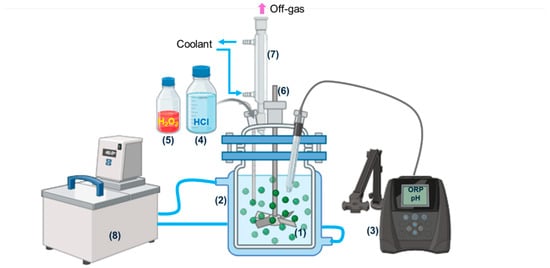
Figure 3.
Schematic illustration of leaching apparatus: (1) Cu-Ni matte + water, (2) glass reactor (1 L), (3) pH/ORP meter, (4) hydrochloric acid, (5) hydrogen peroxide, (6) PTFE agitator (7) condenser, (8) heating bath circulator with oil.
2.2.2. Purification
Copper recovery by sulfide precipitation was carried out using the pregnant leach solution (PLS) in a setup similar to the leaching experiments, but without a condenser, as the tests were conducted at room temperature. Freshly prepared NaHS solution was slowly pumped to the bottom of the PLS over 30 min to minimize sulfide loss as H2S, and the reaction was allowed to continue for 1 h. The amount of NaHS was fixed at 1.5 times the stoichiometric ratio required between NaHS and the copper in the PLS, with agitation maintained at 200 rpm. The same PLS was used to conduct hydroxide precipitation tests, in which the pH was increased to 5 by adding NaOH to the solution while stirring at 200 rpm for 15 min, and the reaction was terminated after 1 h. Cementation tests were also performed using the same PLS to investigate the effect of the type of cementation agent. Iron powder, iron scraps, and iron sheets were used while keeping the agitation rate at 200 rpm, at room temperature, and with iron added at 1.5 times the stoichiometric amount required for copper cementation. The iron was added all at once, and the reaction was allowed to proceed for 1 h.
Iron removal tests were also carried out using a setup similar to that of the copper recovery experiments, using the filtrate obtained after copper removal. First, H2O2 was added to ensure complete oxidation of Fe2+ to Fe3+, which was confirmed by titration analysis. The pH was then adjusted by adding NaOH, and the effect of pH (1–4) on iron removal was investigated under fixed conditions: temperature of 60 °C, agitation rate of 200 rpm, and a reaction time of 1 h.
Cobalt separation by solvent extraction was performed using the filtrate obtained after iron removal. The experiments were conducted in glass separatory funnels and shakers, employing a prepared organic phase of Cyanex 272 diluted in kerosene. The effects of pH (2–7) and Cyanex 272 concentration (10–30% v/v) were investigated under fixed conditions: a temperature of 40 °C, an aqueous-to-organic phase ratio (A/O) of 1, and a single extraction step for shaking for 15 min.
2.2.3. Nickel Carbonate Preparation
Nickel recovery as nickel carbonate was carried out using the raffinate obtained after cobalt separation via solvent extraction, employing a setup similar to the leaching experiments. Na2CO3 was used to adjust the pH of the solution, and the effect of pH (6.5–8) on nickel precipitation was investigated under fixed conditions: temperature of 50 °C, agitation rate of 300 rpm, and a reaction time of 1 h.
Sodium removal tests were conducted using the wet nickel carbonate cake obtained after filtration through a 10 µm filter paper. The solids were mixed with water at a 1:1 volume-to-solid ratio and agitated at 300 rpm in a beaker for 15 min. The mixture was filtered, and this repulping cycle was repeated up to five times.
2.2.4. Sampling and Analysis
The oxidation–reduction potential (ORP) and pH were monitored using Thermo ORION meters equipped with ORP/ATC SJ Gel-Triode and pH/ATC SK Gel-Triode probes at each reaction. To avoid sensor damage in the high-temperature solution specifically in leaching, the probes were inserted into the reactor at regular intervals (e.g., during leaching, every 30 min for the first 2 h and then every 1 h up to 12 h). Each probe was immersed until the displayed values stabilized, typically within approximately 5 min. These measurements provided insights into the reaction mechanism. Liquid samples were collected at regular intervals for kinetic analysis and filtered through 0.45 µm syringe filters. After completion of the reactions, the entire slurry solutions were subjected to vacuum filtration using filter paper. The filtrate volume, as well as the wet and dry weights of the solids, were measured to provide essential data for leaching efficiency calculations and mass balance analysis.
The concentrations of metallic elements and sodium in liquid samples were analyzed using inductively coupled plasma optical emission spectroscopy (ICP-OES, Agilent 5800, Agilent Technologies, Santa Clara, CA, USA). Solid samples were also analyzed after digestion. Elemental mapping of the solids was performed using energy-dispersive X-ray spectroscopy (EDS) with a Thermo Scientific Prisma E Variable Pressure SEM/EDS system. The crystalline phases of the solids were characterized by X-ray diffraction (XRD, PANalytical X’Pert Pro Multipurpose Diffractometer), and chloride content in the solids was determined using ion chromatography (IC, Metrohm AG, Herisau, Switzerland).
3. Results & Discussion
3.1. Upstream: Selective Nickel Leaching
3.1.1. Effect of Acid Concentration
The effect of HCl concentration on the selective leaching of nickel was investigated to maximize nickel extraction while minimizing copper dissolution. As shown in Figure 4, both copper and nickel dissolution increased with rising HCl concentration. The optimal leaching efficiencies were achieved at an HCl concentration of 2.7 M, resulting in 90% nickel extraction with only 10% copper co-extraction, demonstrating the maximum selectivity of nickel over copper. The co-leached copper is presumed to exist as CuO, which exhibits higher solubility than Cu2S in hydrochloric acid. The remaining leach residue, rich in copper as Cu2S, is proposed as a potential feedstock for copper smelters, which could blend it with their primary raw material, chalcopyrite, to recover the copper content.
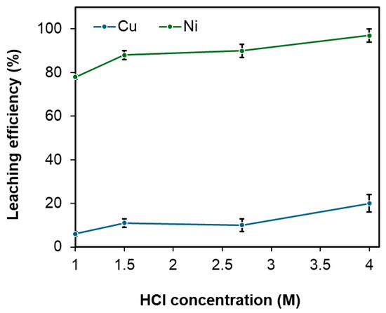
Figure 4.
Effect of HCl concentration on the leaching efficiency of Cu and Ni under fixed conditions: pulp density of 60 wt.%, temperature of 95 °C, leaching time of 12 h, and H2O2 addition at 0.4 M. Error bars represent standard deviation (n = 3).
The variations in Eh and pH during the leaching reactions were monitored throughout the experiments. Under the leaching conditions of 60 wt.% pulp density, 95 °C temperature, 12 h leaching time, and H2O2 addition at 0.4 M, the addition of HCl up to 2.7 M increased the Eh from –0.2 V to 0.4 V, while the pH decreased from 7.5 to 0. The rise in Eh was attributed to the oxidizing environment created by H2O2, whereas the pH decline resulted from the addition of HCl. Corresponding Pourbaix diagrams for copper and nickel, generated using the Medusa simulation tool, are shown in Figure 5a and Figure 5b, respectively. Eh–pH diagrams were generated using the Hydra/Medusa database at 25 °C and used heuristically to rationalize the observed selectivity, while acknowledging their limitations at elevated temperatures. The ionic strength was set to 3.8, based on calculations considering the concentrations and charges of Cu, Ni, Fe, and Cl ions in the PLS under optimal conditions. In particular, the Cl− concentration was set to 2.8 M, corresponding to the optimal HCl concentration discussed in Figure 4.
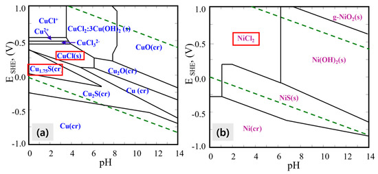
Figure 5.
Eh-pH diagrams for (a) the Cu–S–Cl system and (b) the Ni–S–Cl system under the following conditions: [Cu] = 0.7 M, [Ni] = 0.5 M, [Cl] = 2.8 M, [S] = 0.06 M, ionic strength (I) = 3.8, at 25 °C and 1 atm. The red-framed areas highlight the regions of focus corresponding to the end of the reaction.
As illustrated in Figure 5a, prior to leaching at pH 7.5 and Eh −0.2 V, copper predominantly exists as Cu2S (solid phase) and remains in solid form even after the leaching reaction, appearing as Cu1.75S or CuCl at pH 0 and Eh 0.4 V. Conversely, nickel exhibits distinct behavior; at a high pH of approximately 7.5, nickel is present as NiS, but as the pH decreases to 0 and Eh rises to 0.4 V, nickel becomes soluble, forming NiCl2 as depicted in Figure 5b.
These findings indicate that selective separation of nickel from copper can be achieved by controlling the leaching pH through HCl addition and adjusting Eh via H2O2 to around pH 0 and 0.4 V, respectively. The generated Pourbaix diagrams provide valuable insight into the chemical behavior of Ni and Cu during leaching and support the observed selectivity of nickel over copper under these conditions.
3.1.2. Effect of Oxidizing Agent
In this work, hydrogen peroxide (H2O2) was utilized as an oxidizing agent to facilitate nickel dissolution during the hydrochloric acid leaching process. The primary reaction occurring during leaching is described by Equation (2).
Ni3S2 (s) + 6 HCl (aq) + 3 H2O2 (aq) → 3 NiCl2 (aq) + 2 S (s) + 6 H2O (l)
The concentration of H2O2 was systematically varied from 0 to 1 M to assess its impact on the leaching efficiencies of both nickel and copper. As illustrated in Figure 6, copper dissolution remained largely unchanged with increasing H2O2 concentration. In contrast, nickel leaching efficiency improved with increasing H2O2 concentration up to an optimum level. Beyond 0.4 M H2O2, however, a decline in nickel leaching performance was noted. The decline in nickel leaching efficiency is hypothesized to result from the reductive behavior of H2O2 when its concentration exceeds 0.4 M under the given leaching conditions (pulp density 60 wt.%, temperature 95 °C, HCl concentration 2.7 M, and leaching time of 12 h). At higher concentrations, H2O2 can reduce Cu2+ to Cu+, forming insoluble CuCl that deposits as a diffusion barrier around unreacted Ni3S2. This behavior may also be related to the partial decomposition of H2O2, generating radicals and reducing its effective oxidative power, which can create a slightly reducing environment. In contrast, Cu2S is inherently resistant to leaching, so its dissolution remains unaffected by this barrier. Therefore, an H2O2 concentration of 0.4 M was determined to be optimal, achieving approximately 90% nickel extraction while limiting copper co-extraction to 10%.
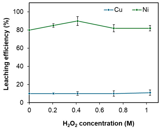
Figure 6.
Effect of the oxidizing agent H2O2 concentration on the leaching efficiencies of Cu and Ni under fixed conditions: pulp density 60 wt.%, temperature 95 °C, HCl concentration 2.7 M, and leaching time of 12 h. Error bars represent standard deviation (n = 3).
3.1.3. Effect of Pulp Density
The influence of pulp density on nickel extraction from Cu-Ni matte was examined. As shown in Figure 7, the nickel extraction efficiency declined from 97% to 79% as the pulp density increased from 40 wt.% to 90 wt.%. This was likely caused by insufficient availability of the leaching agent relative to the stoichiometric demands outlined in Equation (2).
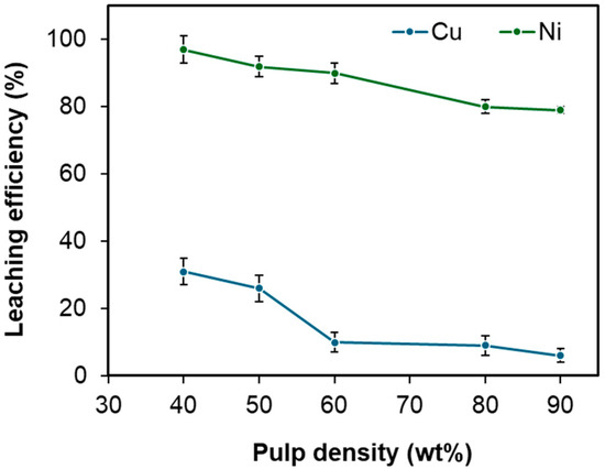
Figure 7.
Effect of pulp density on the leaching efficiencies of Cu and Ni under fixed conditions: temperature 95 °C, duration 12 h, HCl concentration 2.7 M, and H2O2 concentration 0.4 M. Error bars represent standard deviation (n = 3).
Nonetheless, from an industrial perspective, higher pulp densities are desirable as they reduce capital expenditures by decreasing the required size of the leaching reactor. Another important factor to consider is maintaining an adequate Ni2+ concentration in the leachate to ensure effective downstream processing. Taking these considerations into account, a pulp density of 60 wt.% was selected as the optimal condition, balancing efficient nickel extraction (>90%) with practical industrial requirements.
3.1.4. Leaching Mechanism
XRD analysis of the leached residue is shown in Figure 8. During leaching, about 10% of Cu was extracted, while the majority remained as Cu1.8S. This indicates that copper originally present as CuO was dissolved, whereas most of the initial Cu1.8S persisted, and part of the dissolved copper re-precipitated as CuCl in the residue (as evident from the comparison of XRD patterns of the feed material and leached residue). Since approximately 90% of nickel was dissolved during leaching, the residual trace amount is expected to exist as Ni3S2, though it could not be detected by XRD due to its very low concentration. In addition, energy-dispersive X-ray spectroscopy (EDS) mapping was performed for the feed material (Figure 9) to investigate the distribution of nickel and copper. The EDS analysis revealed that Cu was uniformly distributed throughout the feed, whereas Ni was concentrated in localized regions. This distribution likely reflects the selective bonding of Ni within the mineral matrix, which may have contributed to the different leaching behaviors of copper and nickel.
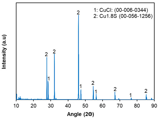
Figure 8.
X-ray diffraction (XRD) pattern of the leached residue obtained after 90% Ni and 10% Cu were extracted under optimal leaching conditions: pulp density = 60 wt.%, [HCl] = 2.7 M, [H2O2] = 0.4 M, temperature = 95 °C, and leaching time = 12 h.
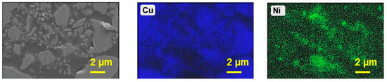
Figure 9.
EDS mapping analysis of the Cu-Ni matte employed as feed material for the leaching process. Mapping was carried out at an accelerating voltage of 20 kV and a dwell time of 100 µs per pixel.
Based on the XRD and EDS observations, together with the leaching efficiencies of nickel and copper and hydrometallurgical principles, the proposed leaching mechanism can be described in three key stages:
- Initial stage: Dissolution of CuO, which encapsulates Ni3S2
- Intermediate stage: Exposure and dissolution of Ni3S2, partial formation of CuCl solids
- Final stage: Reaction control by diffusion of Ni2+ and un-reacted the Cu1.8S remaining
The key reactions relevant to the aforementioned three stages are presented in Equations (3)–(5). The thermodynamic feasibility of each reaction was evaluated by calculating the Gibbs free energy using HSC software version 6.0 at 95 °C, as shown with those reactions.
In the initial stage, CuO preferentially dissolved in localized regions due to its higher solubility compared to Cu1.8S [28,29]. This selective dissolution exposed Ni3S2 sites to the lixiviant, which had previously been encapsulated or closely associated with CuO. During the intermediate stage, the newly exposed Ni3S2 became accessible to reactants (H+ and H2O2), allowing rapid dissolution of Ni. Additionally, there is a possibility of partial reduction of Cu2+ to Cu+ ions due to the effect of some side reactions, such as H2O2 decomposition, which leads to the formation of CuCl, which precipitates due to its low solubility. The formation of CuCl was thermodynamically feasible under the optimal leaching conditions, as shown by the Pourbaix diagram generated using the Medusa simulation tool in Figure 5. The dissolution of Ni and Cu occurred primarily at the particle surface, resulting in the formation of a unreacted core. In the final stage, continued CuCl deposition on the surface of Ni-S associated with unreacted Cu-S caused increase in the thickness of the diffusion boundary layer. Consequently, the diffusion of reactants towards the shrinking Ni3S2 core and the outward diffusion of dissolved Ni2+ ions through this diffusion boundary layer became rate-limiting. Thus, the leaching reaction was chemically controlled in the initial stage and transitioned to diffusion control in the later stages. The proposed leaching mechanism, comprising the aforementioned three key stages, is illustrated in Figure 10.
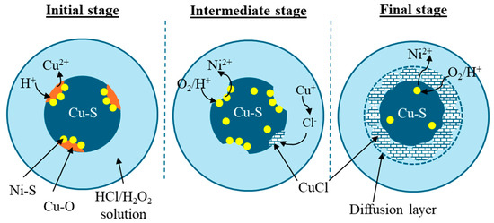
Figure 10.
Proposed leaching mechanism of matte by an oxidative chloride lixiviant.
The leaching behavior of nickel and copper was investigated over time under optimal leaching conditions (pulp density = 60 wt.%, [HCl] = 2.7 M, [H2O2] = 0.4 M, temperature = 95 °C) to elucidate the proposed reaction mechanism. As shown in Figure 11, copper from CuO dissolution was rapidly leached at the initial stage, whereas nickel exhibited slow dissolution during the first 2 h, likely because Ni3S2 remained encapsulated by CuO. After approximately 2 h, the dissolution rate of nickel increased significantly as Ni3S2 became exposed to the acidic solution. Copper concentration began to decrease after 4 h, possibly due to the re-precipitation of dissolved Cu ions as CuCl. From 4 h to the end of the experiment, the nickel leaching rate slowed, which may be attributed to the formation of a CuCl layer on the surface of the remaining nickel, acting as a barrier. Overall, the observed leaching kinetics of nickel and copper are consistent with the proposed reaction mechanism.
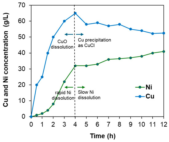
Figure 11.
Leaching behavior of Cu and Ni over time under optimal leaching conditions: pulp density = 60 wt.%, [HCl] = 2.7 M, [H2O2] = 0.4 M, temperature = 95 °C, and leaching time = 12 h.
3.2. Downstream: Purifications
3.2.1. Leached Residue Handling
After subjecting the Cu–Ni matte to the proposed selective leaching method under optimal conditions (pulp density = 60 wt.%, [HCl] = 2.7 M, [H2O2] = 0.4 M, temperature = 95 °C, and leaching time = 12 h), the leach residue was analyzed to confirm nickel and copper leaching efficiencies of approximately 90% and 10%, respectively. Table 4 presents the chemical composition of the leached residue obtained under these conditions, along with the typical compositional range of copper concentrates such as chalcopyrite [30,31]. Blending 7.5 wt.% of this leached residue with 92.5 wt.% of a typical copper concentrate can effectively balance sulfur and chloride inputs while keeping other impurities, such as iron, within acceptable limits for copper smelters, as shown in the fourth column of Table 4.
Table 4.
Comparison of chemical compositions: leached residue vs. typical chalcopyrite, and the resulting blend at 7.5 wt% residue addition.
Moreover, large copper smelters, such as LS MnM in South Korea, operate pretreatment facilities capable of removing certain impurities, including chloride, because they routinely process high-impurity primary and secondary feedstocks. In addition, these smelters employ extensive pyrometallurgical purification steps, which further enhance their ability to accommodate higher blending ratios of copper-rich leached residues. Therefore, incorporating this type of leach residue into the smelter feed at an appropriate ratio would not pose significant processing challenges and could provide an opportunity for copper smelters to maintain side-stream nickel recovery operations alongside primary copper production.
3.2.2. Pregnant Leach Solution (PLS) Handling
After leaching under the optimal conditions, a nickel-rich PLS (40.5 g/L Ni) in a chloride medium was obtained, which is suitable for nickel recovery in the form of nickel carbonate. However, as shown in Table 5, this leachate still contains significant amounts of copper and trace impurities such as iron (Fe) and cobalt (Co), necessitating further purification prior to nickel carbonate precipitation. The downstream purification methods discussed hereafter are based on this pregnant leach solution (PLS).
Table 5.
Chemical analysis of PLS obtained under optimal condition: pulp density = 60 wt.%, [HCl] = 2.7 M, [H2O2] = 0.4 M, temperature = 95 °C, and leaching time = 12 h.
Selective Copper Recovery
- Comparison of different techniques: Despite the majority of copper being removed as leach residue via selective leaching, a considerable amount of copper remained dissolved in the leach solution. To address this, three removal methods, cementation using iron scraps, sulfide precipitation with NaHS, and hydroxide precipitation with NaOH, were evaluated and compared. The precipitation efficiencies of Cu and Ni using different methods were determined using Equation (6).
As illustrated in Figure 12, all methods achieved high copper removal efficiencies exceeding 95%. However, nickel losses due to co-precipitation were substantially higher for sulfide and hydroxide precipitation, resulting in approximately 20% and 25% nickel loss, respectively, whereas cementation limited nickel loss to only 2%. The principal reactions governing cementation, sulfide precipitation, and hydroxide precipitation are presented in Equations (7), (8), and (9), respectively.
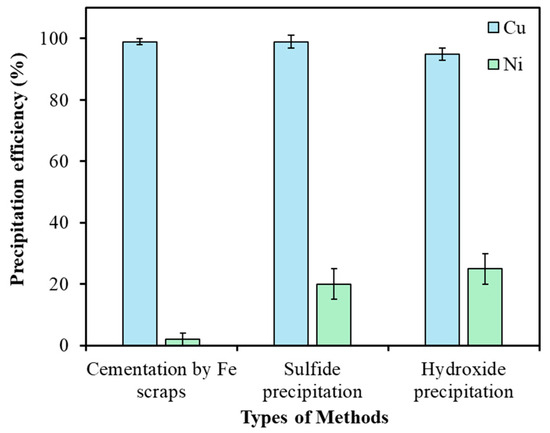
Figure 12.
Comparison of copper removal efficiencies from leach solution using cementation (25 °C, 1 h, Fe scraps at 1.5× equivalent [Cu]), sulfide precipitation (25 °C, 1 h, NaHS at 1.5× equivalent [Cu]), and hydroxide precipitation (25 °C, 1 h, NaOH to pH 5). Error bars represent standard deviation (n = 3).
Furthermore, copper removed through cementation existed in its metallic form, whereas sulfide precipitation resulted in the formation of CuS. The presence of metallic copper offers a distinct advantage, as it can be utilized as a converter coolant in subsequent pyrometallurgical refining processes, unlike CuS. Additionally, sulfide precipitation produces toxic H2S gas, which requires the implementation of strippers and scrubbers for safe gas management, significantly increasing the capital expenditure (CAPEX) of the operation [32]. Taking into account both technical and economic factors, cementation using iron scraps was chosen as the preferred method for eliminating residual copper from the leach solution, achieving copper removal efficiencies exceeding 99%.
- Effect of the type of cementation agent: In this study, iron was introduced in three different physical forms, powder (10 µm), scraps (3–5 cm), and sheets (10 × 10 cm2), as cementation agents, each possessing distinct effective surface areas despite being added in the same quantity based on the Cu to Fe ratio (1.5 times the stoichiometric equivalent of initial [Cu2+] to Fe). Theoretically, iron is capable of reducing both Cu and Ni from the leach solution; however, the reduction of Cu occurs readily due to the larger difference in electrochemical potential values (∆ECu/Fe = 0.78V, ∆ENi/Fe = 0.21 V). The corresponding half-cell reactions are illustrated in Equations (10)–(12). The influence of these different cementation agents is presented in Figure 13. According to Figure 13, the fastest reaction was observed when iron powder was employed, while the slowest occurred with iron sheets. Nevertheless, iron scraps provided the optimal balance in terms of selectivity, achieving approximately 99% Cu reduction and only 2% Ni reduction. In contrast, iron powder resulted in 99% Cu and 10% Ni cementation efficiencies. Furthermore, the consumption of iron powder was higher, which was attributed to an accelerated side Reaction (13) involving iron dissolution in HCl, generating H2 gas; this reaction proceeded more rapidly for iron powder than for scraps or sheets.
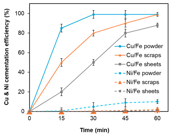 Figure 13. Effect of the type of cementation agent under fixed conditions: temperature 25 °C, reaction time 1 h, and a Cu/Fe ratio equal to 1.5 times the stoichiometric amount of iron required based on the initial Cu concentration according to reaction (7). The iron sources used were iron powder, iron sheets, and iron scraps. Error bars represent the standard deviation (n = 3).
The contact surface area of iron as the cementation agent was found to be a critical factor influencing the efficiency of the copper reduction reaction. Since iron powder, scraps, and sheets possess differing surface areas available for interaction with metal ions, variations in cementation efficiency were anticipated. The impact of the effective surface area of the cementation agents was interpreted through theoretical considerations, as described by Equations (14) and (15) [33]. The kinetic analysis indicated that the cementation rate of Cu2+ depends on the initial Cu2+ concentration, the cementation rate constant, and the effective surface area of iron within a fixed solution volume. Due to its larger effective surface area, iron powder exhibited the highest reaction rate among the tested forms, while other factors such as initial Cu concentration and temperature were maintained constant across all tests.
where [M2+]t = Cu2+ concentration at time t (g/L), [M2+]0 = Initial Cu concentration at t = 0 (g/L), k = cementation rate constant (cm/s), V = volume of solution (cm3), A = effective surface area of Fe (cm2), t = reaction time (s).
Selective Iron Removal
Approximately 60% of iron was co-leached alongside nickel. To eliminate iron ions from the leachate, hydrogen peroxide (H2O2) was first introduced as an oxidizing agent to fully convert Fe2+ ions to Fe3+. Subsequently, iron was precipitated as hydroxide using sodium hydroxide (NaOH), as described by the reactions in Equations (16) and (17). While Fe2+ precipitates at a relatively high pH near 8, Fe3+ can be effectively precipitated within a lower pH range of 2 to 5 [34]. Considering that the initial pH of the leach solution following cementation is low, removal of Fe3+ requires only minimal pH adjustment, thereby reducing NaOH consumption and lowering operational costs. Moreover, performing iron removal at higher pH values leads to increased nickel co-precipitation, highlighting the advantage of operating under low-pH conditions. Prior to precipitation with NaOH, all Fe was confirmed to be present as Fe3+ by redox titration with potassium permanganate, indicating that the conversion efficiency of Fe2+ to Fe3+ by H2O2 exceeded 99%.
The optimal pH for precipitating Fe3+ as hydroxide was experimentally established by varying the pH from 1 to 3. As illustrated in Figure 14, the efficiency of iron removal increased with higher pH values, but this also resulted in increased nickel co-precipitation. At pH 3, iron removal reached 99%, though nickel loss due to co-precipitation was as high as 10%. By balancing these effects, pH 2 was determined to be the ideal condition, achieving 99% iron removal while limiting nickel loss to just 1.9%
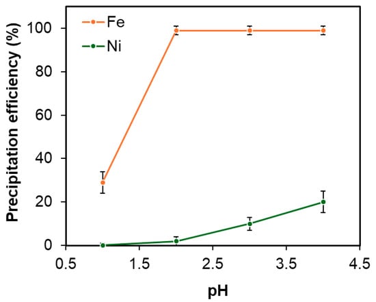
Figure 14.
Effect of pH on Fe removal under fixed conditions: temperature 60 °C, duration 1 h, and H2O2 concentration of 0.01 M. Error bars represent standard deviation (n = 3).
Selective Cobalt Separation
After the removal of all critical impurities, including Fe and Cu, the separation of Co from Ni was carried out prior to the production of nickel carbonate, as some battery manufacturers require cobalt to be controlled within specific purity limits. Due to the similar chemical properties of Co and Ni, simple chemical precipitation techniques were found to be ineffective. Consequently, solvent extraction using Cyanex 272 (Sigma-Aldrich Chemie GmbH, Taufkirchen, Germany) was employed due to its high selectivity for Co over Ni. The separation coefficient (β) for Cyanex 272 is 7000 times greater for Co than for Ni. The effects of extractant concentration (Cyanex 272) and pH on extraction performance were systematically investigated, as illustrated in Figure 15. The results showed favorable selectivity near pH 6, with Co extraction efficiencies of 99%, 97%, and 99% for 10%, 20%, and 30% v/v Cyanex 272 concentrations, respectively. Corresponding, Ni co-extraction rates were 9%, 28%, and 45%. Based on these findings, optimal extraction conditions were determined to be pH 5.7 with 10% v/v Cyanex 272, achieving maximum Co extraction while minimizing Ni co-extraction. Furthermore, the implementation of a two-stage scrubbing process enabled the reduction of co-extracted Ni from 9% to less than 1%. The scrubbed solution was subsequently recycled back to the leaching stage.
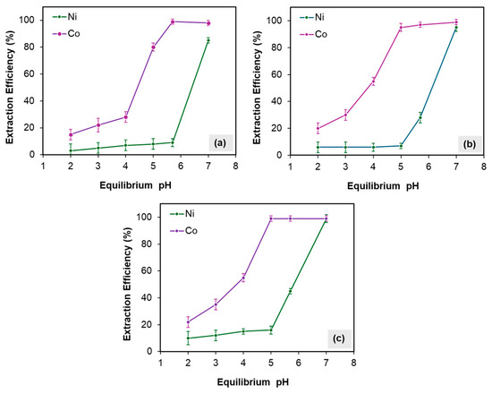
Figure 15.
Effect of pH on Ni and Co at different concentrations of Cyanex 272: (a) 10 (% v/v), (b) 20 (% v/v), and (c) 30 (% v/v) under fixed conditions of A/O =1, temperature 40 °C, and mixing for 15 min. Error bars represent standard deviation (n = 3).
3.3. Preparation of Nickel Carbonate
Following solvent extraction, nickel was precipitated as nickel carbonate from the raffinate using sodium carbonate (Na2CO3), as described by Reaction (18). The influence of pH on nickel recovery was investigated within the range of 6.5 to 8.5, as depicted in Figure 16a. At pH 6.5, nickel recovery reached 75%, while increasing the pH to 7.5 resulted in recovery rates exceeding 99%, with comparable outcomes observed at pH 8.5. Taking into account the consumption of sodium carbonate and the risk of sodium contamination, pH 7.5 was determined to be the optimal condition for nickel carbonate production.
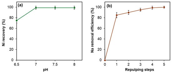
Figure 16.
(a) Effect of pH on nickel recovery under fixed conditions: temperature 50 °C, duration 1 h; (b) effect of repulping on sodium removal from NiCO3 cake. Error bars represent standard deviation (n = 3).
After vacuum filtration of the NiCO3 precipitate using a 10 µm filter paper, it contained 35–45% moisture, varying slightly with pH conditions. The moisture also contained NaCl, produced by reaction (18) and physically entrained on the NiCO3 surface. This NaCl was efficiently removed by applying a repulping technique through multiple repulping steps, as shown in Figure 16b. Through five repulping cycles, the sodium content in the nickel carbonate was reduced from approximately 10,000 ppm to less than 10 ppm.
The resulting nickel carbonate exhibited a light coloration, depicted in Figure 17. The crystal phase of the final product was identified as basic nickel carbonate hydrate (NiCO3·2Ni(OH)2·4H2O) by XRD analysis (ID #00-016-0164). This phase shows higher potential for battery applications due to its higher nickel content and improved control over the stoichiometry of nickel in downstream processes (e.g., conversion to NiSO4). The purity of the final product, nickel carbonate, is presented in Table 6. The total content of key impurities is <1%, indicating a nickel carbonate purity of >99%. This product has high potential for battery applications, possibly after slight additional purification depending on the specific requirements of the battery manufacturer.
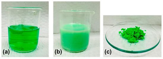
Figure 17.
Images of (a) raffinate from SX (bright emerald green, 100 mL) and (b) during carbonate precipitation (soft green, 100 mL), and (c) nickel carbonate product after filtration (light green, approx. 8 g).
Table 6.
Purity of the NiCO3 produced by the proposed process, showing key impurities.
4. Conclusions
The potential for nickel extraction from a copper-rich industrial intermediate, specifically Cu-Ni matte, was investigated with a focus on applications in both the battery materials industry and copper smelters. The finalized hydrometallurgical process is illustrated in Figure 18.
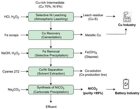
Figure 18.
Proposed hydrometallurgical process for Ni and Co extraction from Cu-Ni matte.
Atmospheric leaching with HCl and H2O2 was employed in lieu of autoclave leaching to enhance cost-effectiveness. Optimal leaching conditions were established as a pulp density of 60 wt.%, HCl concentration of 2.7 M, H2O2 addition of 0.4 M, and a temperature of 95 °C for 12 h. Under these parameters, 90% of nickel was successfully extracted, with only 10% co-extraction of copper, allowing the bulk of copper to remain as leach residue suitable for further refinement via pyrometallurgical processing in copper smelters. A leaching mechanism was proposed, identifying three principal stages governing the leaching of nickel and copper.
To remove residual copper from the leach solution, cementation using iron was determined to be the most effective method, achieving over 99% copper removal with minimal nickel loss (~2%), outperforming sulfide precipitation with NaHS and hydroxide precipitation. The influence of the types of the cementation agents was examined, resulting in the selection of iron scraps as the preferred reductant over iron powder and iron sheets, primarily due to its ability to minimize nickel loss. Residual iron in solution was efficiently eliminated through selective hydroxide precipitation at an optimal pH of 2, yielding greater than 99% iron removal with less than 2% nickel co-precipitation. Subsequently, solvent extraction using Cyanex 272 was employed for cobalt separation, achieving 99% cobalt removal with negligible nickel co-extraction under optimal conditions of 10% v/v Cyanex 272 concentration, pH 5.7, and two scrubbing stages at 40 °C.
Following the removal of key impurities, nickel carbonate was prepared via carbonate precipitation through the addition of Na2CO3. Optimal precipitation conditions were identified as pH 7.5 at 50 °C for 1 h, effectively securing the required purity of nickel carbonate while minimizing sodium contamination. The sodium content in the nickel carbonate product was reduced from approximately 10,000 ppm to less than 10 ppm by repulping.
Under the aforementioned optimal conditions for each stage, a mass balance was performed for nickel, cobalt, copper, and iron based on 600 g of Cu-Ni matte feed material, as shown in Table 7. The resulting mass balances closure is 100 ± 2%. For the input calculations of copper, nickel, and cobalt, their respective contents in the feed material were considered. In addition, for the input calculation of iron, contributions from both the feed material and the iron scrap added during cementation were considered. For the output calculations:
Table 7.
Mass distribution and mass balance of copper, nickel, cobalt and iron under optimal conditions.
- Copper: the total amount in the leached residue and in the copper cement was summed.
- Nickel: the sum included nickel remaining in the leached residue, co-precipitated with copper cement, co-precipitated with iron hydroxide, and present in the final product, nickel carbonate.
- Cobalt: the sum included cobalt remaining in the leached residue, co-precipitated with copper cement, co-precipitated with iron hydroxide, and extracted into the organic phase during solvent extraction.
- Iron: the output was calculated as the sum of iron remaining in the leached residue and iron precipitated as iron hydroxides.
All material balances were calculated using the formula as expressed in Equation (19):
This analysis provides insight into how the mass of each element was distributed throughout the proposed process.
The produced nickel carbonate achieved a purity level of >99%, making it potentially suitable for battery applications, although further refining may be required depending on the specifications of the battery manufacturer. Future research should focus on assessing the technical feasibility of this process through continuous pilot-scale operations, building on the optimal conditions identified in laboratory-scale tests.
Author Contributions
Conceptualization, J.J.W.; Methodology, J.J.W.; Validation, J.J.W.; Formal Analysis, J.J.W.; Investigation, J.J.W.; Writing—Original Draft, J.J.W. and L.M.M.; Writing—Review and Editing, J.J.W., M.S.M., L.M.M. and L.A.; Supervision, L.A.; Funding Acquisition, M.S.M. and L.A. All authors have read and agreed to the published version of the manuscript.
Funding
This research received no external funding.
Data Availability Statement
The original contributions presented in this study are included in the article. Further inquiries can be directed to the corresponding authors.
Conflicts of Interest
Author Janaka Jayamini Wijenayake was employed by the company LS MnM. The remaining authors declare that the research was conducted in the absence of any commercial or financial relationships that could be construed as a potential conflict of interest.
References
- Schmidt, T.; Buchert, M.; Schebek, L. Investigation of the Primary Production Routes of Nickel and Cobalt Products Used for Li-Ion Batteries. Resour. Conserv. Recycl. 2016, 112, 107–122. [Google Scholar] [CrossRef]
- Mistry, M.; Gediga, J.; Boonzaier, S. Life Cycle Assessment of Nickel Products. Int. J. Life Cycle Assess. 2016, 21, 1559–1572. [Google Scholar] [CrossRef]
- Ali, A.-R.; Lackner, J.; Cerdas, F.; Herrmann, C. Analysis of Nickel Sulphate Datasets Used in Lithium-Ion Batteries. Procedia CIRP 2023, 116, 348–353. [Google Scholar] [CrossRef]
- Zhang, H.; Liu, G.; Li, J.; Qiao, D.; Zhang, S.; Li, T.; Guo, X.; Liu, M. Modeling the Impact of Nickel Recycling from Batteries on Nickel Demand during Vehicle Electrification in China from 2010 to 2050. Sci. Total Environ. 2023, 859, 159964. [Google Scholar] [CrossRef]
- Golroudbary, S.R.; Kraslawski, A.; Wilson, B.P.; Lundström, M. Assessment of Environmental Sustainability of Nickel Required for Mobility Transition. Front. Chem. Eng. 2023, 4, 978842. [Google Scholar] [CrossRef]
- Meshram, P.; Abhilash; Pandey, B.D. Advanced Review on Extraction of Nickel from Primary and Secondary Sources. Miner. Process. Extr. Metall. Rev. 2019, 40, 157–193. [Google Scholar] [CrossRef]
- Mubarok, M.Z.; Lieberto, J. Precipitation of Nickel Hydroxide from Simulated and Atmospheric-Leach Solution of Nickel Laterite Ore. Procedia Earth Planet. Sci. 2013, 6, 457–464. [Google Scholar] [CrossRef]
- Hosseini, S.A.; Raygan, S.; Rezaei, A.; Jafari, A. Leaching of Nickel from a Secondary Source by Sulfuric Acid. J. Environ. Chem. Eng. 2017, 5, 3922–3929. [Google Scholar] [CrossRef]
- Hoatson, D.M.; Jaireth, S.; Jaques, A.L. Nickel Sulfide Deposits in Australia: Characteristics, Resources, and Potential. Ore Geol. Rev. 2006, 29, 177–241. [Google Scholar] [CrossRef]
- Mudd, G.M. Global trends and environmental issues in nickel mining: Sulfides versus laterites. Ore Geol. Rev. 2010, 38, 9–26. [Google Scholar] [CrossRef]
- Elias, M. Nickel laterite deposits—Geological overview, resources and exploitation. In Giant Ore Deposits: Characteristics, Genesis and Exploration; CODES Special Publication, 4; University of Tasmania: Hobart, Australia, 2002; pp. 205–220. [Google Scholar]
- Warner, A.E.M.; Díaz, C.M.; Dalvi, A.D.; Mackey, P.J.; Tarasov, A.V.; Jones, R.T. JOM world nonferrous smelter survey Part IV: Nickel: Sulfide. JOM 2007, 59, 58–72. [Google Scholar] [CrossRef]
- Faris, N.; Pownceby, M.I.; Bruckard, W.J.; Chen, M. The direct leaching of nickel sulfide flotation concentrates—A historic and state-of-the-art review Part I: Piloted processes and commercial operations. Miner. Process. Extr. Metall. Rev. 2022, 44, 407–435. [Google Scholar] [CrossRef]
- Wilke, C.R.; Werner, D.M.; Kaas, A.; Peuker, U.A. Influence of the crusher settings and a thermal pre-treatment on the properties of the fine fraction (black mass) from mechanical lithium-ion battery recycling. Batteries 2023, 9, 514. [Google Scholar] [CrossRef]
- Li, J.F.; Wang, B.L.; Xu, M.; Zhu, L.; Lin, L.; Tang, P.P. Process technology on recovery of sulphur from copper-bearing gold concentrate by using kerosene method. Chem. Eng. (China) 2009, 37, 75. [Google Scholar]
- Ning, Z.; Xie, H.; Song, Q.; Yin, H.; Yu-chun, Z. Nickel leaching from low-grade nickel matte using aqueous ferric chloride solution. Rare Met. 2019, 38, 1199–1206. [Google Scholar] [CrossRef]
- Zhu, Z.; Zhang, W.; Pranolo, Y.; Cheng, C.Y. Separation and recovery of copper, nickel, cobalt and zinc in chloride solutions by synergistic solvent extraction. Hydrometallurgy 2012, 127, 1. [Google Scholar] [CrossRef]
- Cheng, C.Y.; Barnard, K.R.; Zhang, W.S.; Zhu, Z.W.; Pranolo, Y.K. Recovery of nickel, cobalt, copper and zinc in sulphate and chloride solutions using synergistic solvent extraction. J. Chem. Eng. 2016, 24, 237. [Google Scholar] [CrossRef]
- Xie, H.; Qu, J.; Ning, Z.; Li, B.; Song, Q.; Zhao, H.; Yin, H. Electrochemical co-desulfurization-deoxidation of low-grade nickel-copper matte in molten salts. J. Electrochem. Soc. 2018, 165, E578. [Google Scholar] [CrossRef]
- He, L.H.; Zhao, Z.W.; Zhang, Y.X. Synthesis of nickel ferrite precursors from low grade nickel matte. Trans. Nonferrous Met. Soc. China. 2013, 23, 2422–2430. [Google Scholar] [CrossRef]
- Cui, F.; Mu, W.; Wang, S.; Xin, H.; Xu, Q.; Zhai, Y. A sustainable and selective roasting and water-leaching process to simultaneously extract valuable metals from low-grade Ni-Cu matte. JOM 2018, 70, 1977–1984. [Google Scholar] [CrossRef]
- Park, K.H.; Mohapatra, D.; Reddy, B.R.; Nam, C.W. A study on the oxidative ammonia/ammonium sulphate leaching of a complex (Cu–Ni–Co–Fe) matte. Hydrometallurgy 2007, 86, 164–171. [Google Scholar] [CrossRef]
- Hofirek, Z.; Kerfoot, D.G.E. The chemistry of the nickel-copper matte leach and its application to process control and optimization. J. Hydrometall. 1992, 29, 357–381. [Google Scholar] [CrossRef]
- Park, K.H.; Mohapatra, D.; Reddy, B.R. A study on the acidified ferric chloride leaching of a complex (Cu–Ni–Co–Fe) matte. Sep. Purif. Technol. 2006, 51, 332–337. [Google Scholar] [CrossRef]
- Naftal’, M.N.; Kuznetsov, N.S.; Naboichenko, S.S.; Solntsev, K.A.; Bryukvin, V.A. Development of the nickel-refining production at Norilsk Nickel Harjavalta Oy in GMK Norilsk Nickel. Russ. Metall. (Metally) 2019, 2019, 495–506. [Google Scholar] [CrossRef]
- Bellemans, I.; De Wilde, E.; Moelans, N.; Verbeken, K. Metal losses in pyrometallurgical operations—A review. Adv. Colloid Interface Sci. 2018, 255, 47–63. [Google Scholar] [CrossRef]
- Zhang, Q.; Zheng, X.; Lv, W.; He, M.; Yan, W.; Gao, W.; Ning, P.; Cao, H.; Sun, Z. An acid-free process to prepare battery grade nickel and cobalt sulfates from complex resources. Nat. Commun. 2025, 16, 1–11. [Google Scholar] [CrossRef]
- Navarro, M.; May, P.M.; Hefter, G.; Königsberger, E. Solubility of CuO (s) in highly alkaline solutions. Hydrometallurgy 2014, 147, 68–72. [Google Scholar] [CrossRef]
- Kociołek-Balawejder, E.; Mucha, I. The influence of CuxS particles on the thermal decomposition of anion exchangers. J. Therm. Anal. Calorim. 2024, 149, 13825–13838. [Google Scholar] [CrossRef]
- Wen, S.; Liu, J.; Deng, J. Chapter 5—Component release of fluid inclusions in sulfide mineral. In Fluid Inclusion Effect in Flotation of Sulfide Minerals; Elsevier: Amsterdam, The Netherlands, 2021; pp. 97–150. [Google Scholar] [CrossRef]
- Castellón, C.I.; Toro, N.; Gálvez, E.; Robles, P.; Leiva, W.H.; Jeldres, R.I. Froth Flotation of Chalcopyrite/Pyrite Ore: A Critical Review. Materials 2022, 15, 6536. [Google Scholar] [CrossRef] [PubMed]
- Chan, Y.H.; Lock, S.S.M.; Wong, M.K.; Yiin, C.L.; Loy, A.C.M.; Cheah, K.W.; Chai, S.Y.W.; Li, C.; How, B.S.; Chin, B.L.F.; et al. A state-of-the-art review on capture and separation of hazardous hydrogen sulfide (H2S): Recent advances, challenges, and outlook. Environ. Pollut. 2022, 314, 120219. [Google Scholar] [CrossRef]
- Wijenayake, J.J.; Lee, S.Y.; Park, S.H.; Sohn, H.S. Production of ferronickel from limonitic laterite ore using hydrogen reduction and cementation. Hydrometallurgy 2021, 203, 105622. [Google Scholar] [CrossRef]
- Balintova, M.; Petrilakova, A. Study of pH influence on selective precipitation of heavy metals from acid mine drainage. Chem. Eng. Trans. 2011, 25, 345–350. [Google Scholar] [CrossRef]
Disclaimer/Publisher’s Note: The statements, opinions and data contained in all publications are solely those of the individual author(s) and contributor(s) and not of MDPI and/or the editor(s). MDPI and/or the editor(s) disclaim responsibility for any injury to people or property resulting from any ideas, methods, instructions or products referred to in the content. |
© 2025 by the authors. Licensee MDPI, Basel, Switzerland. This article is an open access article distributed under the terms and conditions of the Creative Commons Attribution (CC BY) license (https://creativecommons.org/licenses/by/4.0/).