Abstract
High-pressure hydrogen compatibility evaluations of alloys using hollow specimens were performed in accordance with ISO 7039. Hollow tensile specimens containing high-pressure hydrogen gas in a small-diameter hole along the axis can also be used to evaluate the influence of hydrogen gas without using high-pressure vessels. This method is not only simpler and less costly than the conventional approach, but it can also evaluate the instantaneous change in the environmental gas at specimen break. The following findings were obtained from slow-strain-rate tensile (SSRT) tests in a high-pressure hydrogen gas environment using hollow specimens of austenitic stainless steels: (1) the work hardening of the specimen in the SSRT tests stopped several minutes before the crack reached the outer surface owing to the influence of hydrogen; (2) the work hardening of the specimen resumed immediately after the hydrogen gas was released; (3) the crack growth took several minutes to reach the specimen’s surface; and (4) the fracture surface was not a cleavage fracture. These results indicate that materials are still ductile after exposure to the high-pressure hydrogen environment. This can be explained by the fact that hydrogen does not embrittle the material itself but inhibits the work hardening of the material. This phenomenon can be explained by the behavior of chemical bonds among atoms, and more discussion on strength from the perspective of chemical bonds is expected.
1. Introduction
There have been many reports on the hydrogen compatibility of structural materials—in the 1960s mainly for space-launching vehicles and in the 2000s for fuel cell cars. NASA has conducted hydrogen gas embrittlement research on the Space Shuttle main engine. A detailed review of previous hydrogen gas embrittlement studies was performed [1]. Hydrogen gas embrittlement evaluations have been conducted for many types of metallic materials. Based on its hydrogen gas embrittlement evaluations of tensile properties, NASA’s hydrogen gas embrittlement table [2] is widely used, including as a reference for high-pressure hydrogen storage in fuel cell vehicles.
In recent years, reports on pipeline materials have increased. For example, Michler et al. reviewed the influence of a hydrogen pressure exceeding 100 MPa on the tensile properties and fatigue crack growth rates of various steels [3]; Shin et al. evaluated hydrogen embrittlement susceptibility using in situ small-punch tests [4]; and Chowdhury et al. summarized the microstructure of materials, the behavior of hydrogen, and several mechanisms of hydrogen embrittlement, including fracture toughness [5].
A brittle fracture is the sudden or rapid fracture of materials under stress less than the yield strength, where the crack propagates at the sound velocity and the fracture surface is a cleavage fracture. However, in most reports, “hydrogen embrittlement” refers to a reduction in strength or toughness under certain testing conditions. These properties change according to the conditions. Most discussions are based on the behaviors of dislocations or vacancies.
In metallic materials, the microstructure, strength, and toughness are significantly affected by the additive elements, which are attributed to the interatomic interactions. The essence of this interaction can be understood through the chemical bonding between atoms. Previously, Griffith assumed that the strength and fracture results in the subjects of intermolecular forces, which were a function of the relative orientation of the attractive force among molecules [6]. In other words, strength and fracture are also determined by chemical bonds. In the 1960s, discussions on orbital electrons were active, and Goodenough [7] considered magnetism as something that fluctuates depending on chemical bonds, chemical structure, and electronic structure, and, in particular, described the distinction between the localized electron model and the collective electron model in solids, their mutual relationship, and their relationship to magnetism. Pettifor [8] focused on d orbital electrons and quantitatively explained the structural trend observed across the transition metal series as the number of valence electrons N increases from 3 to 11. In the 1980s, Briant et al. showed a charge density calculation between elements in steel by the molecular orbital method [9]. Morinaga et al. discussed the d electron behavior using electronic structure calculations by the DV-Xα cluster method and new alloying parameters in Ni-based ternary alloys obtained from the calculations [10]. Grigorovich introduced the metallic bond and the structure of metals from the viewpoint of orbital electrons [11]. In recent years, Trolier-McKinstry et al. [12] discussed the bonding between different atoms and ions related to hardness, melting points, and boiling points. Ohtsuka et al. [13] showed changes in the position and distribution of carbon atoms on the energy and physical properties using first-principles calculation and molecular dynamics methods. Many studies have been conducted to understand orbital electrons, first-principles calculations, and the investigation of alloy states using the molecular orbital method. However, there have been no calculations of stressed and/or strained practical conditions, and the understanding of orbital electrons is not widespread.
The author performed slow-strain-rate tensile tests (SSRTs) in high-pressure hydrogen environments using hollow specimens [14,15,16,17,18,19,20,21] under various conditions and obtained results on the influence of hydrogen on the mechanical properties [19]. The advantages of an SSRT in high-pressure hydrogen environments using hollow specimens are that the costs for the equipment and/or maintenance are very low, and the test temperature can be easily changed from low to high. This is because it does not require a high-pressure vessel, which is used in the conventional method using solid specimens. The SSRT results for hydrogen using hollow specimens were qualitatively and almost quantitatively the same as those of the conventional method [19]. This hollow specimen method has been published as ISO 7039-2024 [22].
In SSRTs in hydrogen using a hollow specimen, the crack initiated from the inner surface and then reached the outer surface, breaking the specimen and releasing high-pressure hydrogen gas. However, the austenitic stainless-steel specimens sometimes did not break entirely but resumed work hardening and continued to deform in the hydrogen-depleted environment. Consequently, this method can also be used to evaluate the instantaneous change in the environmental gas at the specimen break. The results obtained using this method were not well explained by conventional understanding based on dislocation behavior but were clearly understood by considering the interactions between the orbital electrons of the materials and hydrogen.
In this study, unique and original SSRT results obtained by hollow specimens in a high-pressure hydrogen environment are introduced, and the strength and effect of hydrogen from the viewpoint of orbital electrons and metallic bonds are discussed.
2. Materials and Methods
The materials used in this study were commercial stainless steels SUS304, SUS316L, and SUS630 from Japanese industries. The chemical compositions of the alloys are presented in Table 1. SUS316L, with its stable austenite phase, is less affected by hydrogen. SUS304, with its low Ni content and no Mo, has an unstable austenite phase and is affected by hydrogen when it transforms into martensite, but it is cheaper than SUS316L. SUS630 is a martensitic stainless steel with high strength but it is easily affected by hydrogen. Typical austenitic stainless steels, SUS304 and 316L, were solution-treated at 1323 K for 0.5 h. The heat treatment of martensitic stainless steel SUS630 was as follows: 1303 K × 1 h, water-quenching, 753 K × 10 h, and air-cooling.

Table 1.
Chemical compositions of SUS304, SUS316L, and SUS630 used in this study (weight %).
Hollow-type round tensile specimens were machined from the bars, and their outer diameter (D) in the gauge length was 6.25 mm, as shown in Figure 1. The hollow (hole) in the specimen was machined by an electro-discharge and wire-cut, and its diameter (d) was less than 2 mm. The maximum roughness (Rmax) of the surface of the hole was measured using a 3D laser scanning microscope and was approximately 8 μm [14,21].
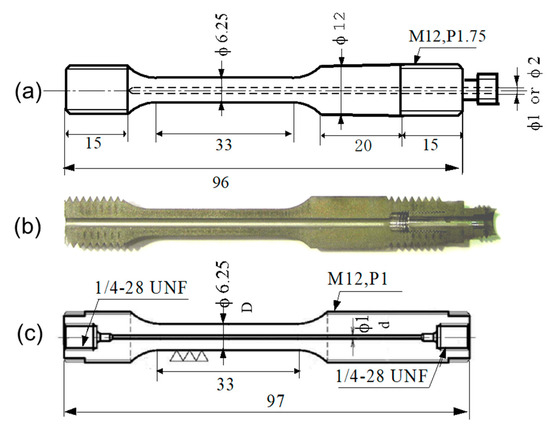
Figure 1.
Geometries of hollow specimens: (a) dimensions of the earlier type with welded joint, (b) a half-cut view, and (c) the latest type with machined joint (unit: mm).
Figure 2 shows an illustration of the testing system with the hollow specimen for evaluating the mechanical properties under high-pressure hydrogen gas. The high-purity (7N grade) hydrogen gas (H2) and helium (He) gases were used. The specimen hole and connecting pipes were vacuum-pumped and purged more than three times. High-pressure gas was filled into a small hole in the specimen from a compressor or cylinder. For tests with H2, analysis of the H2 at the inlet of the specimen was performed using a trace oxygen meter and a dew point meter as needed.
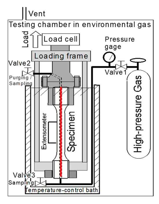
Figure 2.
Schematic diagram of a mechanical properties testing method for a high-pressure hydrogen environment using a hollow specimen [19]. The red line in the center of the specimen is a hollow space that is filled with high-pressure hydrogen or an inert gas.
The temperature of the environmental gas and specimen can be changed by a refrigerant or a heater from 20 K to 1000 K. The test temperatures in this study were room temperature (RT, 300 K) and low temperatures (260, 250, 240, 230, 210, 190, 170, 150, 135, 120, 110, and 77 K). The tensile specimens containing H2 or He were cooled using temperature-controlled alcohol and liquid nitrogen spray. The nominal strain rate for the SSRT was 2.8 × 10⁻⁵ s−1 (3.6 mm/h). The total testing time in He at RT was 6–8 h. The data sampling rate was 0.5 s. The specimen temperature was measured using a thermocouple attached to the specimen surface at the middle of the gauge length. The tests were started one hour after the inside pressure was set.
During the SSRT, the amount of strain-induced martensite (α’) was measured using Ferrite Scope, and its probe was pointed at the specimen. The fractured surfaces of the specimens were observed using a scanning electron microscope (SEM).
The influence of hydrogen was evaluated by the relative reduction in area (RRA, Zh(rel) in ISO) and/or the relative tensile strength (RTS, Rmh(rel) in ISO standard), which are the ratios of those properties in a H2 environment to those obtained in He. A ratio of 1.0 indicates no influence of H2, and the ratio decreases as the influence of hydrogen increases.
where
Reduction in area (RA) = {(Do2 − do2) − (Df2 − df2) }/(Do2 − do2)
Do: the diameter of the parallel section before the test;
Df: the diameter of the parallel section after the test;
do: the inner diameter of the hole before the test;
df: the inner diameter of the hole after the test.
The details of the testing procedures are described in previous reports [14,20] and in ISO 7039 [22].
3. Results
3.1. Results of the Hollow Specimen Method
Figure 3a–c show the stress–stroke curves of SUS304, SUS316L, and SUS630 at 14 MPa and 70 MPa hydrogen gas (H2) and 11 MPa helium gas (He) at room temperature and low temperatures in previous studies [14,15,16,17,18,19,20]. In SUS304, the specimens failed earlier in H2, and lower tensile strength, elongation, and reduction in area were obtained. The influence of H2 was maximum at approximately 190 K and was small in SUS316L. In H2, both specimens were fractured when the amount of α’ exceeded 40% [18].
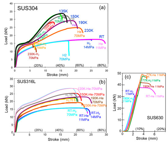
Figure 3.
Load–stroke curves for (a) SUS304, (b) SUS316L, and (c) SUS630 at room temperature (RT) and low temperatures in 11 MPa or 70 MPa hydrogen or helium gas using the hollow specimen.
SUS630 showed a significant influence of H2, and the specimens failed before reaching the yield strength, except at 77 K. In SUS630, the influence of H2 was maximum at approximately 230–250 K [20].
Figure 4 shows the influence of hydrogen and temperature on the relative reduction in area for SUS316L, SUS304, and SUS630. Figure 5 shows the fracture surfaces of SUS630 at RT in 10 MPa hydrogen gas (a,b) and 10 MPa helium gas (c). Although SUS630 failed before reaching the yield strength in H2, the fracture surface did not exhibit any cleavage.
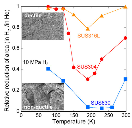
Figure 4.
Influence of hydrogen and temperature on reduction in area for SUS316L, SUS304, and SUS630.
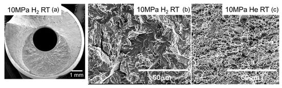
Figure 5.
Fracture surfaces of SUS630 at RT in 10 MPa hydrogen gas (a,b), and in 10 MPa helium gas (c).
3.2. Replacement of H2 to He During Testing
Figure 6 shows the results of experiments in which H2 was changed to He during the SSRT for SUS316L at 190 K [18]. The 70 MPa H2 in the hollow of the specimen was replaced with 11 MPa He at a stress close to the fracture stress in the H2. During the gas replacement, loading was stopped, and a small relaxation was observed. After gas replacement, the specimen continued to work-harden and deformed almost the same amount as the specimen in He from the beginning of the test.
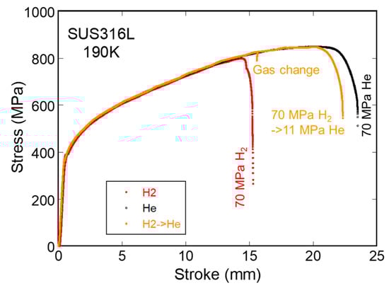
Figure 6.
Stress–stroke curves of SUS316L at 190 K in 70 MPa hydrogen, where hydrogen was replaced with helium gas just before the fracture stress in hydrogen.
Figure 7 shows the gas replacement for the SUS630. At 300 K in 10 MPa H2, the specimen failed at a stress of 1236 MPa. The gas change at 1200 MPa was attempted, but the specimen failed within several seconds during the stop loading for exchange gas. The specimen for which H2 changed at 1100 MPa was deformed as if no hydrogen was present from the beginning. At 260 K and in 10 MPa H2, this steel failed at 832–1006 MPa, and the specimen that changed gas at 752 MPa (90% of 832 MPa) was deformed as if no hydrogen was present from the beginning.
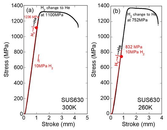
Figure 7.
Stress–stroke curves of SUS630 at 300 K (a) and 260 K (b) in 10 MPa hydrogen, where hydrogen was replaced with helium gas just below the fracture stress in hydrogen [18] (red lines indicate H2).
These tests prove that there is almost no influence of H2 up to the fracture stress in H2.
3.3. Recovery of Work Hardening Just After Hydrogen Leakage
As unique phenomena occurred in the high-pressure H2 SSRTs with hollow specimens, the stress drop just before the specimen break often stopped immediately after the H2 leakage, as shown in Figure 8 for SUS 316L at 105 MPa H2 and 193 K. The figure on the right is an enlarged view of the one on the left just before the fracture. The stress increased again after the stress drop, indicating that the influence of hydrogen disappeared and normal work hardening and ductile crack growth resumed after the drop.
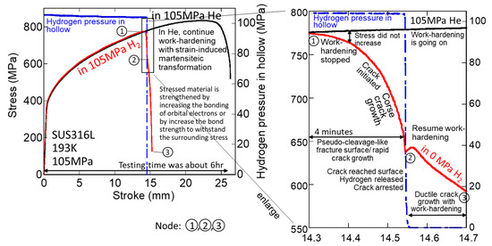
Figure 8.
Stress–stroke curves for 316L at 105 MPa H2 and He at 193 K (red lines indicate H2 and blue lines represent H2 pressure in hollow).
Node 1: The stress–stroke curve for H2 became flat and began to deviate from the stress–stroke curve for He, indicating that work hardening in H2 stopped. The H2 pressure in the hollow was maintained at >100 MPa.
The stress–stroke curve began to decline, and the drop gradually increased, indicating that a crack was initiated and coarse crack growth progressed.
Node 2: The crack reached the specimen surface and H2 leaked, and the H2 pressure in the hollow became 0 MPa immediately, after which the crack propagation stopped, and the specimen did not break. Work hardening resumed, and ductile crack growth progressed with work hardening.
Node 3: The specimen fractured.
Figure 9 shows the fracture surface of SUS 316L at 105 MPa H2 and 193 K. No cleavage surface was observed on the fractured surface. A crack initiated at the inner surface of the hole and reached the outer surface of the specimen, following which H2 was released, and ductile crack growth proceeded.
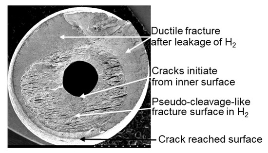
Figure 9.
Fracture surface of SUS 316L at 105 MPa H2 and 193 K.
The stress–stroke curves for SUS 304 at 13 MPa H2 and He at RT are shown in Figure 10, and the same phenomenon can be observed. These phenomena for SUS 304, 316L, and other meta-stable austenitic steels occur frequently at lower temperatures owing to the influence of H2 on the strain-induced martensitic transformation during work hardening.
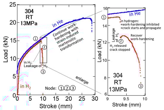
Figure 10.
Stress–stroke curves for SUS304L in 13 MPa H2 and He at RT (red lines indicate H2 and blue lines stand for H2 pressure in hollow; nodes are the same as in Figure 8).
Figure 11 shows the load–stroke curves for SUS630 at 230 K in 70 MPa H2 or He for hollow specimens. In the 70 MPa H2 environment, the specimen broke at a stress lower than that of the proportional limit. The fracture stress was approximately 640 MPa, which is approximately 0.3% of Young’s modulus. It took more than 10 s for the crack to reach the specimen surface, which was far slower than the sound velocity, and the fracture surface did not exhibit cleavage, which is slightly different from the brittle fracture.
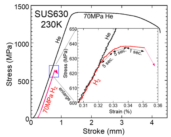
Figure 11.
Load–stroke curves for SUS630 at 230 K in 70 MPa H2 and He gas for the hollow specimen (crosshead speed: 0.001 mm/s; data sampling interval: 0.5 sec; red lines indicate H2).
4. Discussion
4.1. Validity of Hollow Specimen for the Evaluation of Hydrogen Compatibility
Hydrogen compatibility is generally evaluated using the ratio of the mechanical properties obtained in H2 to those obtained in He or other inert gases. In previous studies [14,19,21], it was proven that the influences of the hole and inner pressure on the obtained mechanical properties were almost negligible. The values of the relative reduction in the area of various austenitic stainless steels at 80–300 K obtained with the hollow specimens were almost the same as those obtained with the solid specimens [23,24,25]. This discussion was also confirmed in the process of publishing ISO 7039.
4.2. Replacement of H2 to He During Testing
As shown in Figure 6 and Figure 7, when H2 disappeared, the effects of hydrogen also disappeared, and the specimens deformed as if no hydrogen was present from the beginning. Therefore, it can be concluded that the materials themselves do not become brittle in H2, at least at a stress of 90% of the fractured stress in H2.
4.3. Recovery of Work Hardening and Deformation Just After Hydrogen Release
The recovery of work hardening immediately after H2 leakage is shown in Figure 8, and Figure 10 is the first report that the material had been exposed to a high-pressure H2 environment, but the H2 environment was instantly removed. For SUS304, SUS316L, and SUS630, even if the pressure is low, the momentary release of H2 would cause crack growth to stop and work hardening and deformation to resume.
Brittle fracture is the sudden or rapid fracture of materials under stress less than the yield strength; the crack propagates at sound velocity, and its fracture surface exhibits cleavage. As shown in Figure 8, the specimen took several minutes to break after the crack was initiated, the elongation was more than 30%, and no cleavage occurred; thus, this is not a brittle fracture, although the obtained strength and elongation are lower than those in He. Even in the case of SUS630, as shown in Figure 11, it took several seconds to fail, and the fracture surface was not cleavage.
The phenomenon that the apparent stress drop stopped immediately after the hydrogen leakage might be explained by the relaxation of the stress at the crack tip due to the loss of internal pressure; however, the stress due to the internal pressure was small [21]. As shown in Figure 8 and Figure 10, the stress increased after the pressure drop, and the slope of the drop was close to that in He, which indicated that the effect of hydrogen disappeared, and work hardening resumed. The fact that the rapid crack growth by H2 stopped immediately after the release of H2 can be explained by the assumption that the rapid crack growth is not due to the accumulation of defects but to the interruption by H2 of work hardening in the process of increasing the strength to withstand the increase in applied stress.
The results obtained from the SSRT using the hollow specimen lead to the following considerations and discussions.
4.4. What Is Work Hardening? What Is the Strength?
Conventionally, it has been explained that as plastic deformation progresses and dislocations accumulate, dislocations become more difficult to move, and the strength of the materials increases, which is known as work hardening. However, why does the strength increase as the defects accumulate? Is the material not more brittle as defects accumulate?
Grigorovich [11] described dislocations or defects as the formation of interatomic bonds by overlapping valent and subvalent electron shell orbitals. He also mentioned that in a compressed lattice, the decrease in the distance between metal atoms leads to stronger overlapping of their outer and subvalent shells, and the melting point increases. Therefore, it can be considered that in the stressed or strained lattice or atoms, the overlapping of interatomic bonds by orbital electrons increases not only in the outer s shells but also in the valent d(t2g) orbitals; that is, the strength also increases with the applied energy. An increase in overlap indicates an increase in the number of chemical bonds, including π, δ, and σ bonds. The phenomenon of the ‘accumulation of dislocations’ is an increase in the overlapping of bonds with the movements of atoms, which is the essence of work hardening. The limit of the increase in overlap is the fracture strength. The essence is the metabolism for the stability of energy and is considered an atomic activity. Therefore, to understand the essence of the strength and influence of hydrogen, we must realize that materials are composed of atoms bonded with orbital electrons.
We must also understand that the orbital electrons of materials not only change their spin but also change their orbitals, hybridization partners, and bonding orbitals, increase the number of orbitals added to the bond and the bond strength, and recombine the bonds using energy from the surroundings. Lattice structures, hcp, fcc, and bcc are the results of the hybridization of orbitals [12,26]. The hcp and fcc bonds are due to hybridization of the p-orbitals, whereas the bcc bond is due to the fact that the p-orbitals are not involved in the main bond. The lack of p-orbital is considered to demonstrate a lower tendency for re-bonding and higher energy at re-bonding, which causes an increased chance of interaction with H2. Unpaired dyz-dzx-dxy orbitals together with s-orbitals form strong sd3 hybrid orbitals <111> [8,26,27], resulting in bcc, which has higher strength.
This is the same as the energy metabolism in quantum biology, and hydrogen steals energy from the exited and unpaired electrons to change its orbital and excites itself. Excited hydrogen releases energy elsewhere as heat and light. As a result, hydrogen inhibits the work hardening of bonds, which leads to a decrease in strength.
4.5. A New Explanation of Plastic Deformation and Work Hardening
The atoms that make up a substance bond by sharing the energy fields of orbital electrons with similar energy levels, lowering their own energy state, and giving and receiving energy from each other to maintain stability [26]. When force energy is applied, atoms attempt to reduce or absorb the energy to withstand the force energy by converting antibonding orbitals into bonding orbitals to create new s-, p-, or d-bonds, and then recombining to increase the bond energy, resulting in an increase in strength. Strain-induced martensitic transformation is a phenomenon in which bonds are rearranged to increase strength, and expansion relieves external forces. Dislocations observed using a transmission electron microscope are ‘shadows’ of the high-energy bonds that cannot be penetrated by the electron beam. The higher the testing speed, the greater the energy, which makes recombination easier. In a tensile test, the displacement increases monotonically at a constant rate, which is a test condition that differs from that in a practical environment. The higher the tensile strain rate, the higher the strength. Thus, the tensile strength is much higher than the true strength of the materials. The limit of re-bonding to withstand environmental forces is the strength of the materials.
From the above discussion, plastic deformation and phase transformation can be explained by the recombination of neighboring atoms to relax and absorb the strain energy received from surrounding forces. It is not a magical ‘dislocation’ that moves and swaps the positions of the atoms. The assumed real plastic deformation is illustrated in Figure 12 and proceeds as follows:
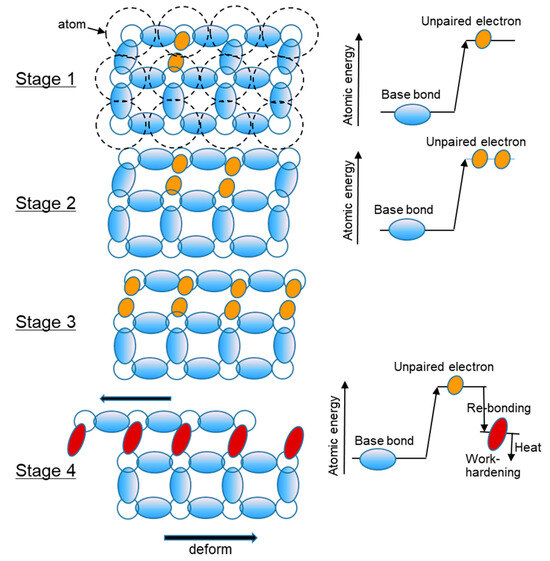
Figure 12.
Illustration of the plastic deformation process.
Stage 1: The strain energy from the surroundings excites the bonded orbital electrons, resulting in the formation of unpaired electrons in the orbital.
Stage 2: The bonded orbital electrons to be re-bonded are excited by energy to become unpaired electrons. If unable, they return to the original state with AE (acoustic emission) or heat generation. A large number of aligned unpaired electrons are required for re-bonding.
Stage 3: The bond of orbital electrons that re-bond in several subgrains is excited and becomes unpaired electrons. Re-bonding proceeds between the nearest neighbors with the energy and stops when there is disorder in the sequence of bonds. If re-bonding is not possible, the material returns to elastic deformation instead of plastic deformation.
Stage 4: The energy after re-bonding is lower than the excited energy, but the overlapping of bonds increases, the energy (strength of bond) is higher, and the remaining energy is released as heat of deformation. As re-bonding progressed within the aligned electrons, the subgrains with strengthened bonds through re-bonding increased and became fine grains as a result of work hardening.
4.6. A New Explanation of Fatigue and Delayed Fracture
When a force is applied from the surroundings that exceeds the original bonding force of a substance, the bonding force is increased to correspond to the force to reduce the change, as in self-induction. It is considered that the splitting of the orbital occurs not only by the electric field but also by stress. Figure 13 presents a familiar illustration of the splitting of the d orbitals of iron by the electric field and excitation energy. It can be inferred that this is true not only when electric field energy is applied but also when a force is applied.
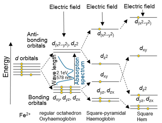
Figure 13.
An illustration of the splitting of the d orbitals of iron by the electric field and excitation energy.
Under the proportional limit, the antibonding orbitals of the s, p, and d orbital electrons are changed to bonding orbitals by the force (energy) from the surroundings before the recombination of the orbital electrons to bond with the neighboring atoms occurs. This is believed to increase the bond strength. This indicates an increase in the strength of the elastic deformation. The σ, π, and δ bonds are between the s, p, and d orbital electrons of neighboring atoms. If the atoms are aligned in an undisturbed manner, as in the case of whiskers, the strengthening will continue, and the strength will increase. When the energy required to increase the bond strength exceeds the energy required for local recombination with neighboring atoms, local and reversible recombination with neighboring atoms to relax the strain begins, and the proportional limit becomes the elastic limit.
Under repeated stress, σ, π, and δ bonds are formed at peak stresses, separated at lower stresses, and revert to non-bonding orbitals, and this cycle continues. However, the same stress can only cause non-bonding orbitals to become bonding orbitals once or a limited number of times (for example, rechargeable batteries also deteriorate with repeated charging). The limited number of times depends on the stress; therefore, orbital electrons from other atoms become bonding orbitals, increasing the overall strength of the material. Cracks initiate owing to the increase in the antibonding orbitals which never change to bonding orbitals.
When a certain number of the antibonding orbitals (corresponding to “vacancies” in conventional theory) accumulate and the bonding orbitals that increase strength disappear, the material can no longer sufficiently increase its strength against external forces, and fatigue cracks initiate, propagating planarly owing to the lack of surrounding bonding orbitals, as shown in Figure 14.
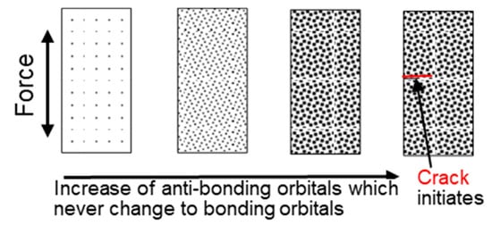
Figure 14.
A new explanation of the fatigue mechanism.
Striations are the remnants of bonds that barely managed to become bonding orbitals and withstand the force.
In the case of delayed fracture including weldments with residual stress, materials are constantly subjected to forces in practical conditions, and to withstand these forces at even below the yield strength, they transmit them to their surroundings or use their own bond energy to recombine the σ, π, and δ bonds continually. If hydrogen is present during the recombination, energy is taken from the bond that has become an unpaired electron, and the bond becomes an antibonding orbital that cannot change to a bonding orbital. If the number of the antibonding orbitals increases and the bonding orbitals that increase strength disappear, rapid delayed fracture occurs.
The addition of Ni, which has a number of valence electrons, and annealing can improve fatigue and delayed fracture life by increasing the number of orbitals that can change to a bonding orbital.
4.7. Hydrogen Excitation and Mechanism of Embrittlement
The author has discussed that in the process of work hardening, a number of unpaired electrons with higher energy are produced. Under these conditions, as reported by Masuda [28], the potential field is lowered, and the unpaired electrons exhibit magnetism. Especially, the dz2 orbitals are considered to exhibit magnetism, and because hydrogen also exhibits magnetism, hydrogen is attracted to the unpaired electrons. Then, hydrogen steals energy from the unpaired electrons, which are ready to increase the strength and inhibit the work hardening of the bonds. Therefore, owing to the increase in the antibonding orbitals, the materials fail earlier in H2.
5. Conclusions
- (1)
- The hollow specimen is effective for evaluating hydrogen compatibility, as described in ISO 7039.
- (2)
- The materials themselves do not become brittle in H2 in the SSRT, at least at a stress of 90% of the fractured stress in H2.
- (3)
- The fact that hydrogen was released and crack growth stopped can be explained by assuming that crack growth is not an accumulation of defects (dislocations), but rather that “hydrogen prevents work hardening”.
- (4)
- The strength of materials is determined not by the behavior of dislocations but by the type and number of chemical bonds between atoms that change their bonding partners depending on the applied or surrounding energy.
- (5)
- Hydrogen does not embrittle the material itself but interferes with the work hardening of materials by stealing energy from unpaired electrons. Consequently, the material appears brittle because it breaks earlier at lower strength and ductility values.
- (6)
- In a delayed fracture, hydrogen increases the number of the antibonding orbitals, and when the bonding orbitals that increase strength disappear, rapid brittle fracture occurs.
- (7)
- The author suggests that more scientists study the strength and fracture from the viewpoint of a quantitative model of stressed orbital electron–hydrogen interactions.
Funding
This work received no external funding.
Data Availability Statement
The original contributions presented in this study are included in the article. Further inquiries can be directed to the corresponding author.
Conflicts of Interest
The author declares no conflicts of interest.
References
- Jewett, R.P.; Walter, R.J.; Chandler, W.T.; Frobmberg, R.P. Hydrogen Environment Embrittlement of Metals, NASA CR-2163; NASA: Washington, DC, USA, 1973. Available online: https://ntrs.nasa.gov/api/citations/19730012717/downloads/19730012717.pdf (accessed on 30 January 2023).
- NASA: Safety Standard for Hydrogen and Hydrogen Systems, Guidelines for Hydrogen System Design, Materials Selections, Operations, Storage, and Transportation; NSS 1740.16; NASA: Washington, DC, USA, 1997; p. A-93. Available online: https://ntrs.nasa.gov/api/citations/19970033338/downloads/19970033338.pdf (accessed on 8 December 2023).
- Michler, T.; Wackermann, K.; Schweizer, F. Review and Assessment of the Effect of Hydrogen Gas Pressure on the Embrittlement of Steels in Gaseous. Metals 2021, 11, 637. [Google Scholar] [CrossRef]
- Shin, H.S.; Kang, S.B.; Pascua, R.; Bae, K.O.; Park, J.; Baek, U.B. Effect of Hydrogen Pressure and Punch Velocity on the Hydrogen Embrittlement Susceptibility of Pipeline Steels Using Small Punch Tests under Gaseous Hydrogen Environments at Room Temperature. Metals 2023, 13, 1939. [Google Scholar] [CrossRef]
- Chowdhury, M.F.W.; Tapia-Bastidas, C.V.; Joshua Hoschke, J.; Venezuela, J.V.; Atrens, A. A review of influence of hydrogen on fracture toughness and mechanical properties of gas transmission pipeline steels. Int. J. Hydrogen Energy 2025, 102, 181–221. [Google Scholar] [CrossRef]
- Griffith, A.A. The Phenomena of Rupture and Flow in Solids. Philos. Trans. R. Soc. Lond. Ser. A 1921, 221, 163–198. [Google Scholar]
- Goodenongh, J.B. Magnetism and the Chemical Bond (Interscience Monographs on Chemistry, Inorganic Chemistry Section. Vol. I); Interscience Publishers: New York, NY, USA; London, UK, 1963. [Google Scholar]
- Pettifor, D.G. Theory of the crystal structures of transition metals. J. Phys. C Solid State Phys. 1970, 3, 367. [Google Scholar] [CrossRef]
- Briant, C.L.; Messmer, R.P. An Electronic Model for the Effect of Alloying Elements on the Phosphorus Induced Grain Boundary Embrittlement of Steel. Acta Metall. 1982, 30, 1811–1818. [Google Scholar] [CrossRef]
- Morinaga, M.; Yukawa, N.; Adachi, H. Alloying Effect on the Electronic Structure of Ni3Al (γ′). J. Phys. Soc. Jpn. 1984, 53, 653–663. [Google Scholar] [CrossRef]
- Grigorovich, V.K. The Metallic Bond and the Structure of Metals; NOVA Science Publishers, Inc.: New York, NY, USA, 1989; ISBN 0-941743-50-0. [Google Scholar]
- Trolier-McKinstry, S.; Newnham, R.E. MRS Bulletin Materials Engineering: Bonding, Structure, and Structure-Property Relationships. MRS Bull. 2019, 44, 510–511. [Google Scholar] [CrossRef]
- Ohtsuka, H.; Tsuzaki, K. Recent Studies on the Nature and State of Carbon Atoms in Iron. ISIJ Int. 2021, 61, 2677–2686. [Google Scholar] [CrossRef]
- Ogata, T. Evaluation of Hydrogen Embrittlement by Internal High-Pressure Hydrogen Environment in Specimen. Jpn. Inst. Met. Mater. 2008, 72, 125–131. (In Japanese) [Google Scholar] [CrossRef]
- Ogata, T. Hydrogen Embrittlement Evaluation in Tensile Properties of Stainless Steels at Cryogenic Temperatures. In Advances in Cryogenic Engineering, Proceedings of the Transaction of the International Cryogenic Materials Conference, Chattanooga, TN, USA, 16–20 July 2007; American Institute of Physics (AIP): College Park, MD, USA, 2008; Volume 54, pp. 124–131. [Google Scholar] [CrossRef]
- Ogata, T. Hydrogen Environment Embrittlement Evaluation in Fatigue Properties of Stainless Steel SUS304L at Cryogenic Temperatures. In Advances in Cryogenic Engineering, Proceedings of the Transaction of the International Cryogenic Materials Conference, Tucson, AZ, USA, 28 June–2 July 2009; American Institute of Physics (AIP): College Park, MD, USA, 2009; Volume 56, pp. 25–31. [Google Scholar] [CrossRef]
- Ogata, T. Influence of High Pressure Hydrogen Environment on Tensile and Fatigue Properties of Stainless Steels at Low Temperatures. In Advances in Cryogenic Engineering, Proceedings of the Transaction of the International Cryogenic Materials Conference, Spokane, WA, USA, 13–17 June 2011; American Institute of Physics (AIP): College Park, MD, USA, 2011; Volume 58, pp. 39–46. [Google Scholar] [CrossRef]
- Ogata, T. Hydrogen Environment Embrittlement on Austenitic Stainless Steels from Room Temperature to Low Temperatures. In Advances in Cryogenic Engineering—Materials, Proceedings of the International Cryogenic Materials Conference (ICMC) 2015, Tucson, AZ, USA, 28 June–2 July 2015; IOP Publishing: Bristol, UK, 2015; Volume 102, p. 012005. [Google Scholar] [CrossRef]
- Ogata, T. Simple Mechanical Testing Method to Evaluate Influence of High Pressure Hydrogen Gas. In Proceedings of the ASME 2018 Pressure Vessels and Piping Conference ASME PVP2018-84187, Prague, Czech Republic, 15–20 July 2018. [Google Scholar]
- Ogata, T. Influence of 70 MPa Hydrogen Gas on SUS 630 from 77 K to 373 K by Simple Testing Method. In Proceedings of the ASME 2018 Pressure Vessels and Piping Conference ASME PVP2018-84462, Prague, Czech Republic, 15–20 July 2018. [Google Scholar]
- Ogata, T.; Ono, Y. Influence of Roughness of Inner Surface of Simple Mechanical Testing Method to Evaluate Influence of High Pressure Hydrogen Gas. In Proceedings of the ASME 2019 Pressure Vessels and Piping Conference ASME PVP2019-93492, San Antonio, TX, USA, 14–19 July 2019. [Google Scholar]
- ISO 7039-2024; Metallic Materials—Tensile Testing—Method for Evaluating the Susceptibility of Materials to the Effects of High-Pressure Gas Within Hollow Test Pieces. ISO: Geneva, Switzerland, 2024. Available online: https://www.iso.org/standard/82610.html?browse=ics (accessed on 31 July 2024).
- Han, G.; Fukuyama, S.; Yokogawa, K. Effect of Strain-induced Martensite on Hydrogen Environment of Sensitized Austenitic Stainless Steels at Low Temperatures. Acta Mater. 1998, 46, 4559–4570. [Google Scholar] [CrossRef]
- Sun, D.; Han, G.; Vaodee, S.; Fukuyama, S.; Yokogawa, K. Tensile behavior of type 304 austenitic stainless steels in hydrogen atmosphere at low temperatures. Mater. Sci. Technol. 2001, 17, 302–308. [Google Scholar] [CrossRef]
- Fukuyama, S.; Sun, D.; Zhang, L.; Wen, M.; Yokogawa, K. Effect of Temperature on hydrogen Environment of Type 316 Series Austenitic Stainless Steels at Low Temperatures. Jpn. Inst. Met. Mater. 2003, 67, 456–459. (In Japanese) [Google Scholar] [CrossRef]
- Ogata, T. Development of Mechanical Testing Methods, Standardization and Strengths and Orbital Electron. Bull. Iron Steel Inst. Jpn. 2018, 23, 404–413. Available online: https://portal.isij.or.jp/ferrum/PDF/PDFOpen_New.php?PNAME=OPN/VOL02308/2018_Vol.023_No.08_0404.pdf (accessed on 29 July 2025). (In Japanese).
- Fujita, E. Structure of interstitial solid solutions. Bull. Jpn. Inst. Met. 1967, 9, 647. (In Japanese) [Google Scholar] [CrossRef]
- Masuda, H. Movement of Hydrogen during SCC of SUS310S Stainless Steel. ECS Trans. 2011, 33, 1. [Google Scholar] [CrossRef]
Disclaimer/Publisher’s Note: The statements, opinions and data contained in all publications are solely those of the individual author(s) and contributor(s) and not of MDPI and/or the editor(s). MDPI and/or the editor(s) disclaim responsibility for any injury to people or property resulting from any ideas, methods, instructions or products referred to in the content. |
© 2025 by the author. Licensee MDPI, Basel, Switzerland. This article is an open access article distributed under the terms and conditions of the Creative Commons Attribution (CC BY) license (https://creativecommons.org/licenses/by/4.0/).