Abstract
Inconel 718 is considered the most widely adopted nickel-based superalloy, and drilling of this alloy is always challenging for researchers. Cemented carbide twist drills have been evaluated in the drilling of this alloy by changing the cutting environment or by varying the tool geometry. In the latter case, the cutting speed has been extended from 30 m/min to 60 m/min when drills are micro-textured or ground. In this study, contrary to cemented carbide twist drills, for the first time, inserts named stepped (central) and peripheral (wiper) are evaluated in the drilling of this alloy. The central insert is designed for balanced forces, while the peripheral is a wiper insert designed for better surface finish. Drilling experiments are conducted in flood cooling conditions with a 12 mm diameter twist drill equipped with novel stepped and wiper inserts at varying cutting speeds (25, 35, and 45 m/min) and feed rates (0.04, 0.06, and 0.08 mm/rev). At a cutting speed (Vc) of 25 m/min and feed rate (f) of 0.04 mm/rev, 25 holes are drilled with roughness (Ra) values ranging from 0.40 µm to 0.60 µm, which represents a significant increase in the number of holes per drill and improved surface finish over to previous work. The new inserts showed almost three-fold longer tool life compared to a standard drill bit at a higher Vc of 45 m/min and 0.04 mm/rev f with an Ra between 0.22 µm to 0.43 µm, which is deemed acceptable for aerospace applications. In addition, minimal surface and sub-surface defects were observed, eliminating the need for a post-drilling finishing operation; therefore, a one-step drilling operation was achieved.
1. Introduction
The usage of superalloys in an aerospace turbine engine is almost 50% of the total materials, and nickel alloy (Ni-alloy) shares account for ~40% [1]. Nickel-based superalloys are the family of metallic alloys that the aerospace manufacturing industries have widely adopted, especially in structural components due to outstanding properties such as resistance to corrosion, fracture toughness, better yield and high-temperature strength. However, this alloy is in a category of difficult-to-machine materials is due to low thermal conductivity and greater susceptibility toward work hardening [2]. Among Ni- alloys, Inconel 718 is still the most widely consumed alloy. Compared to turning and milling, data on the drilling process is limited [3]. So far, conventional drilling methods have been found to be less effective and less productive; therefore, researchers have adopted various techniques to improve the machining efficiency for drilling Inconel 718. Previously, peck drilling [4] and pilot hole-making strategies [5] were also adopted by the researchers, but poor hole quality and low productivity, respectively, were the common problems associated with these approaches. A thorough summary of literature reviews on drilling of Inconel 718 in particular, and the machining of nickel alloys in general, is presented below for context building.
Several researchers have attempted to change the cutting environment for holes’ quality improvement while drilling Inconel 718. Nearly all researchers have employed cemented carbide twist drills while studying the variations in the cutting environment while drilling Inconel 718. Shah et al. [6] drilled 50% more holes at a maximum Vc of 20 m/min using liquid CO2 compared to liquid nitrogen due to less chipping and abrasion wear with the former. Reductions in surface roughness (11%), power consumption (19%), and thrust force (14%) were noticed with liquid CO2, but deteriorating effects of carbon dioxide usage were reported in terms of environment, human health, and natural resources depletion. Thus, liquid nitrogen was recommended as the superior cryogenic coolant over carbon dioxide because of its lesser environmental damage. Eskandari et al. [2] recommended an efficient method of cooling for drilling Inconel 718 by adding graphene nanoplatelets blended in cutting fluid at a constant Vc of 30 m/min and f of 0.05 mm/rev. The particle size of graphene was within the range of 7 µm. By applying the cutting fluid having graphene in it caused the reduction in the value of cutting torque from 6 Nm to 2 Nm. Moreover, cutting with graphene-based cutting fluid resulted in approximately 10% improvement in surface roughness. Additionally, deformation zone depth and subsurface strain magnitude were lower in the presence of graphene-based cutting fluid than in flooded cooling. A reduction of ~33% in the cutting temperature was recorded with the former cutting scheme. At the same time, the authors did not recommend dry cutting of Inconel 718 due to Sa values escalating to 35 µm. Three modes of cutting environment was investigated by Girinon et al. [7] (internal high-pressure cooling (via drill), external low-pressure cooling, and dry condition) on the resulting residual stresses and surface quality. Cutting speed (c) and feed rates (f) were constant at 24 m/min and 0.10 mm/rev, respectively. Girinon recommended internal high-pressure cooling for compressive residual stresses and limited strain hardened layer. Contrary to internal high-pressure cooling, dry drilling produced severe tensile residual stresses and a thick strain-hardened layer below the machined surface. Ucak et al. [8] analyzed the holes drilled in Inconel 718 by investigating the thrust forces, torque, rise in temperature, surface quality, and tool life under various drilling conditions at constant Vc of 15 m/min and 0.02 mm/rev f. With a cryogenic cutting environment, a substantial reduction in cutting temperature was noticed, along with an improvement in integrity of the hole and quality of the hole. However, an increase in thrust force and a reduction in tool life were seen along with tool chipping when cutting in a cryogenic environment due to an increase in the hardness and strength of the workpiece material. Better results in terms of lower surface roughness and higher tool life were achieved when applying Flood cooling. Furthermore, TiAlN coating dramatically enhanced the tool life. Khanna et al. [3] compared dry drilling with the cryogenic environment at a constant speed of 19 m/min and 0.02 mm/rev. The latter arrangement not only improved the tool life by about 87% but also reduced the torque by about 30%. In addition, improvement in hole quality attributes was also recorded with a decrease in circularity error (up to 51 %), cylindricity error (up to 77 %), and roughness value (up to 48 %). Furthermore, dry drilling was not recommended by the authors considering the tool life and hole integrity. Apart from drilling, oil emulsion was suggested to be the better feasible option when turning Inconel 718 as referred by Amigo et al. [9]. In their work, CO2 cryogenic cooling was recommended for Hayness 263 for providing a good balance between environmental and technical aspects. As per Pereira et al. [10], cryoMQL, which is a combination of MQL and cryogenic technique, showed a 57% increase in tool life in the milling of Inconel 718 in comparison to MQL technology. However, the performance of this technique was inferior in comparison to wet machining. It is important to mention that the use of cutting fluid is mandatory in turning, drilling, and milling of Ni-based superalloys such as Inconel 718, RR 1000,Haynes 282 and Waspaloy [11,12,13,14].
Qin et al. [4] employed peck drilling (seven pecks for each hole), which led to poor hole quality as measured by higher surface roughness (Ra = 2–5 µm), material smearing, cavities, grooves, and side flow. Rahim and Sasahara [15] recommended palm oil over synthetic ester due to its effective lubrication and cooling. A reduction in surface roughness and sub-surface plastic deformation was noticed with palm oil due to its high viscosity. Karabul and Kaynak [16] conducted dry drilling experiments on additively manufactured Inconel 718 at a Vc of 30 m/min, f of 0.075 mm/rev. However, a high surface roughness of 2.5 µm-Ra was recorded along with an increased microhardness beneath the machined surface (extended to around 100 µm). From the above discussion, it can be noted that 30 m/min was the maximum cutting speed employed by the researchers while evaluating various cutting environments during the drilling of Inconel 718. Furthermore, it can also be commented that the drillability of Inconel 718 is not promising in a dry-cutting environment.
The second area in which researchers tried to improve the drilling efficiency of Inconel 718 is the geometric modification of the carbide twist drill bit. Pang and Wang [1] evaluated micro-textured implanted drills at 30 m/min Vc and 0.20 mm/rev f. The laser surface texturing technique was utilized for texturing the flank and rake surfaces. Improvements in the drilling process were noticed with lower values of tool wear, drilling temperature (up to 9%), and thrust force (up to 32 %) compared to conventional drilling. Micro-texturing enhances the air convection on the tool surface with faster heat dissipation, thus improving the aforementioned responses. Beer et al. [17] compared the performance of standard and modified twist drills at a Vc of 35 m/min and an f of 0.10 mm/rev. The flutes of modified carbide twist drills were ground to reduce roughness below Rz = 0.50 µm to improve chip evacuation and chip jamming problems. Additionally, a groove having a depth of 50 µm was generated at the face of the flank in parallel to the cutting edge (at a distance of 200 µm from the cutting edge) by using the laser melting method. With this modification, a ~12% improvement in the tool life was noticed as opposed to a standard drill bit. Modified twist drills generated 3–5 µm-Rz roughness, which is marginally better (10%) in comparison to the standard drill bit. The performance of modified carbide twist drills was presented in refs. [18,19], where the flank face was retracted via a grinding process to create a cooling flow channel (just behind the cutting edge) to improve the accessibility of the cutting fluid (flowing from the internal drill hole) towards the area of cutting edge corners. At 45 m/min Vc and 0.14 mm/rev f, a ~3-fold tool life improvement was noticed with this modified drill compared to the standard drill bit. Additionally, the standard drill generated 28% higher roughness values than that obtained with modified drills, where the roughness was 5–7.5 µm-Rz with the latter drills [18]. Vrabel et al. [20] also evaluated ground carbide twist drills at Vc = 20 m/min and f = 0.035 mm/rev in the presence of an internal flood coolant supply. With this parametric combination, 24 holes were drilled. From the above discussion, it is evident that a higher Vc of up to 45 m/min can be employed with the modification in carbide twist drills, and, at the same time, improved surface quality and higher tool life could be achieved.
According to ref. [20], drilling is typically considered a roughing operation for the Inconel 718 alloy, and reaming is a necessary finishing operation. Sharman et al. [5] suggested a pilot hole-making approach to drill Inconel 718. To drill 8 mm holes, firstly, 7.8 mm pilot holes were drilled, making this process less productive. They found that the surface roughness was less than 0.50 µm-Ra with the finishing operation, while it was up to 1.50 µm-Ra with the drilling operation. The sub-surface plastic deformation was also 2–3 times lower with the finishing operation compared to the drilling process. Drilling also revealed material smearing and welding of the chip to the hole walls, contrary to the finishing operation. They suggested employing finishing (either reaming or mill-boring) to meet the tight requirements of aerospace applications, as drilling of Inconel 718 is deemed insufficient.
From the above discussion, it is evident that previously published literature on the Inconel 718 drilling is focused on using cemented carbide twist drills only by using the various cutting environments or by using the geometrically modified twist drills. Additionally, dry drilling is generally not recommended for this alloy. A maximum cutting speed of 30 m/min is achieved with variations in the cutting environments, such as using liquid CO2, liquid nitrogen, and graphene-based fluids. With modified twist drills, better roughness can be achieved, and cutting speeds can be extended up to 45 m/min. Few researchers have also considered the drilling of Inconel 718 as a roughing operation, pointing out the need for some finishing operations. Therefore, the current research status for drilling Inconel 718 is that the post-drilling operations, including reaming and mill boring, are still mandatory, and drilling operation alone is not enough to meet aerospace requirements.
In general, drilling superalloys is always challenging, and researchers continuously try various techniques to improve machinability. More recently, ultrasonic peening drilling (UPD) has been proposed to increase fatigue life, induce compressive residual stresses, better surface finishes, and raise microhardness. In this methodology, ultrasonic elliptical vibrations and tool rotations are both applied clockwise [21]. On the same analogy, ultrasonic-assisted milling has been introduced by generating impacts on the machined surface ultrasonically during end milling. Compared to conventional milling, ~16 times greater fatigue life is obtained with a better surface finish and fewer surface defects [22].
Though the advantages of wiper inserts in turning and milling [23,24,25] are well established in terms of productivity, their use in drilling is still lacking. Drill tool manufacturers have now been able to produce the wiper configuration for drilling processes. In this study, wiper inserts are evaluated along with the combination of central inserts (termed as a stepped insert) placed in a special type of tool holder, with a provision of spacious flutes for chip evacuation from the cutting zone. (Figures are shown in the next section). The expected benefits of this combination are improved surface roughness, increased productivity due to the possibility of using higher feed rates, lesser defects on the hole surface, and omitting the need for finishing operations. Hence, it is termed as one-step machining. In this study, the effect of the new wiper and central inserts on the drilling performance of Inconel 718 is evaluated in terms of tool life, tool wear, surface roughness, and surface integrity.
2. Materials and Methods
Inconel 718 was utilized as a workpiece for drilling experimentation. Initially, it was supplied in bar form, having a length of 305 mm and a diameter of 76 mm. Then, several discs measuring a diameter of 76 mm × 15 mm thickness were cut via wire electric discharge machining (EDM). The tool holder selected for the drilling operation was Coro-drill 880, manufactured by Sandvick Coromant. The Coro-drill 880 can mount two inserts: a central insert and a peripheral insert. The peripheral insert has a wiper configuration (termed as wiper insert). In wiper inserts, along with a nose radius, an additional straight edge is introduced, which keeps the cusp height of the machined surface at a lower level due to the increased contact length with the machined surface. Figure 1a shows the schematic of the wiper insert with a nose radius and an additional straight edge. The central insert has a nose radius at the chisel edge location (in the case of a twist drill) where Vc is zero, and material removal is primarily due to extrusion with material transporting away from the center. As with twist drills, the central insert has two cutting edges to remove material by shearing (Figure 1b). However, a central insert features steps on both cutting edges, which reduce cutting-edge involvement compared to standard twist drills, resulting in shorter chips. Both inserts are coated with TiAlN coating. Barrero et al. [26] proposed a post-coating method of droplet elimination via drag grinding to enhance the performance of coated inserts. According to them, droplets on the coatings obstruct the sliding of the chip over the tool surface and cause abrasive wear. Removing such droplets enhanced the performance in drilling. However, the scope of this work is limited to the evaluation of novel carbide inserts in drilling; therefore, inserts were evaluated as received from the manufacturer. This aspect will be considered for future work, and the topography of coatings will be taken with an optical profilometer to analyze the droplets’ effects.
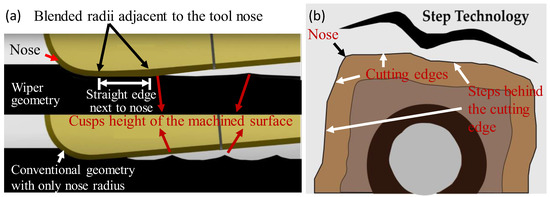
Figure 1.
Schematic of (a) wiper insert with an additional straight edge adjacent to nose for increased contact length, and (b) central inserts with steps on the cutting edges.
The chemical composition of Inconel 718 was in line with the standard, see Table 1.

Table 1.
Chemical Composition of Inconel 718 (standard vs. actual).
Unlike a conventional drill, the central inserts are also provided with the chip breaker, which offers better chip breakability/chip evacuation and smooth shearing that leads to balanced drilling forces, see Figure 2. As only one wiper insert is provided at the outer periphery along with the central insert, the question of unbalanced radial forces arises. This balance is provided by the uniform distribution of weight provided in the tool holder. Otherwise, machining with unbalanced radial forces can cause severe vibrations and affects the hole integrity. The details of the drills used are shown in Table 2.
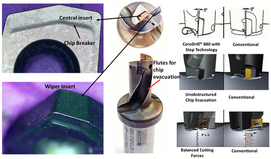
Figure 2.
View of Coro Drill 880 fitted with a central and a peripheral (wiper) insert.
Table 2.
Details of the Coro Drill 880 drills employed for Inconel 718.
Makino v33i, a vertical machining center with 3 axes and a maximum RPM of 20,000 RPM and 20 HP, was utilized to drill Inconel 718. The setup for conducting the experiments when drilling is shown in Figure 3, with a workpiece and inserts mounted on the tool holder. The cutting fluid was directed via a two-nozzle interface between the tool and workpiece with a flow rate of 20 L/min to remove excessive heat generated during the process. At first, an attempt was made to use dry drilling with the new drill. However, dry drilling resulted in excessive tool wear with catastrophic fractures of both central and peripheral inserts, even at the lowest operating parameters (see Figure 4). This indicated the inaptness of the dry drilling operation for Inconel 718. This observation was in line with the previously reported literature [2,7], highlighting the significance of flood coolant. Drilling, turning, and milling of Inconel 718 is mostly conducted in the presence of cutting fluids, as surface integrity is of utmost concern during machining [11,27,28]. Consequently, drilling was conducted in flooded conditions later on.
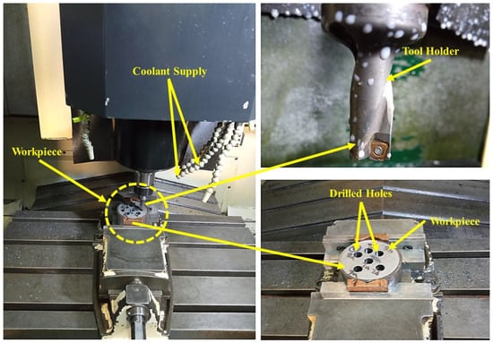
Figure 3.
Experimental setup on the vertical machining center showing the workpiece and cutting inserts mounted on the tool holder.
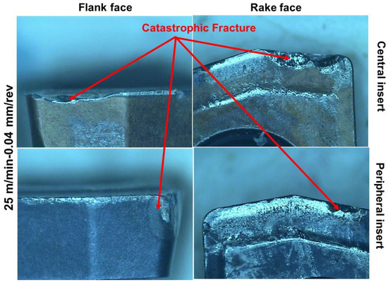
Figure 4.
Catastrophic fracture of the inserts after drilling one hole without cutting fluid at Vc = 25 m/min and f = 0.04 mm/rev.
Table 3 shows the levels of input variables. Nine experiments were conducted in the flooded condition by employing a full factorial experimental design, as shown in Table 4. Cutting speed and feed rate at three levels were used for experimentation. The Vc and f levels were carefully selected from the literature [4,7,17]. For instance, a maximum Vc of 45 m/min was reported in the studies [18,19] for drilling the nickel-based superalloy; however, in general, cutting speeds were within 15–30 m/min [2,3,8]. Since productivity was the prime concern, a 45 m/min cutting speed was also considered in the current experimentation. The lower value of Vc at 25 m/min was to check the benefit of these inserts in terms of maximum tool life. Another objective of this work was to omit the post-drilling finishing operation (e.g., reaming) and make the drilling process a one-step operation, while keeping the f within the range used in the previous studies [3,29].
Table 3.
Levels of input parameters.
Table 4.
Design of experiments based on full factorial design.
Since these inserts are novel, limited inserts were supplied by the manufacturer. Even then, it was planned to replicate all experiments to ensure conformity and confidence in the results. Due to the fracture and breakage of the inserts during dry drilling, four experiments involving Test 2, Test 3, Test 4, and Test 8 were replicated. The results of these replications were within 10% of each other. Each experiment was conducted until the tool life reached the maximum flank wear criterion of 200 µm, which was set both for central and wiper inserts. If either central or wiper inserts reached the set criterion of flank wear, the test was terminated. Tool wear was measured via a coordinate measuring machine (CMM), supplied with a camera of a magnification of 70×, with a PC running the Quadra Check (QC)-5000 software. For a spindle runout of ≤5 µm, burr detection was carried out using a CMM machine with a probe at the entry and exit of the last hole of all experiments. The burr formation is quite critical in drilling as it affects dimensional accuracy, jamming, and misalignment problem, as suggested by Pena et al. [30]. They emphasized the importance of chisel edge and chip evacuation via larger channels to avoid burr formation. They used spindle signals to detect burr formation, which was further processed via an algorithm for calculating the magnitude. The drilled holes were sliced into two halves by wire EDM to observe the surface roughness, hole surface, and sub-surface damage. Before the start of any experiment, tool images were captured to check the conformity of the edges. A portable roughness tester was used to measure the surface roughness at a cut-off length of 0.8 mm and evaluation length of 4 mm. Four random locations were selected for measuring the surface roughness of drilled holes, and their average values were reported in this study. Surface and sub-surface damage and cross-sectional images were captured via an optical microscope and a scanning electron microscope SEM (Joel 6060). Samples were prepared and etched as per standard operating practices used for Inconel 718. A summary of the research methodology used in this work is summarized in Figure 5.
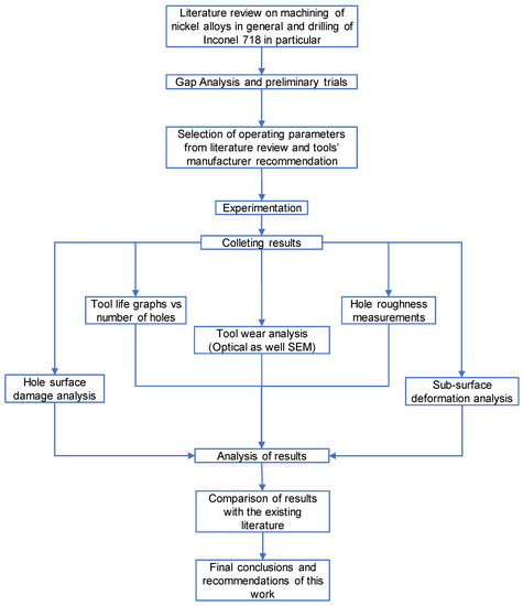
Figure 5.
Research methodology framework used.
3. Results
3.1. Tool Life
Figure 6 presents the tool wear progression with the number of drilled holes for wiper inserts, and Figure 7 shows the trend in wear progression of the central insert. Interestingly, no significant difference in tool wear was noticed with either of these inserts, indicating the suitable design combination of both these inserts in the tool holder. A maximum of 25 holes were drilled at 25 Vc and 0.04 f, therefore, considered as optimal parameters in terms of drilled holes. By escalating the feed rate from 0.06 f to 0.08 mm/rev while keeping Vc fixed, 40% and 60% reductions in the number of drilled holes were noticed, respectively. At 35 Vc and 0.04 f, 19 holes were drilled, which were reduced to just 9 and 7 at 0.06 f and 0.08 f, respectively. At the highest cutting speed of 45 m/min, no catastrophic fracture was observed. With 15 holes drilled at 0.04 mm/rev, this parametric combination can be considered as optimal in terms of productivity. Again, an increase in the feed rate reduced the number of holes to just four, but tool wear was still not catastrophic. A comparison of the current work with the existing literature is critical to compare the performance of these novel inserts. The current work cannot be compared with approaches such as peck drilling [4] and pilot hole making [5] in terms of tool life due to poor productivity associated with these. However, a comparison with the other existing literature is provided. According to Shah et al. [29], although they preferred liquid CO2 to liquid nitrogen when drilling Inconel 718, they only drilled 11 holes at a Vc of 20 m/min and a f of 0.04 mm/rev. In contrast, in Test 1 of our work, even at a higher Vc of 25 m/min and the same feed rate of 0.04 mm/rev, 126% more holes (25 total holes) were drilled. In the drilling of Inconel 718, Khana et al. [3] produced 27 holes at 200 µm flank wear criterion in a cryogenic environment at 20 Vc and 0.02 mm/rev f. In Test 1, at the double value of f, a comparable number of 25 holes were drilled. Studies that reported on geometrically modified twist drill tools [17,18,19] provided a reasonable comparison with the current work by using a 45 m/min Vc with a volumetric material removal of 43 cm3/min. However, in our work (Test 9), the material removal rate was 54 cm3/min, which is 26 percent higher than the previous work with a tool life of 4 min.
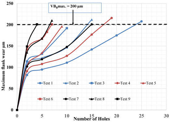
Figure 6.
Flank wear against the number of holes for wiper (peripheral) insert.
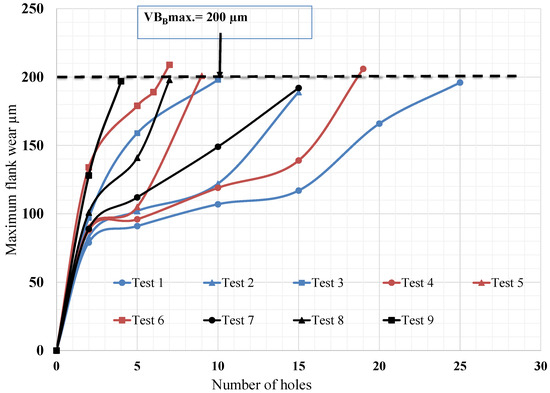
Figure 7.
Flank wear against the number of holes for the central insert.
The mechanics behind the better performance of the central and wiper insert combination compared to twist drills were attributed to shorter chips (shown in Figure 8), better chip evacuation, and balanced forces during the cutting and sweeping action of the greater contact length of the wiper insert (see Figure 9) at the outer periphery. The provision of the nose radius (of the central insert) at the chisel edge location extruded the material instead of squeezing and ploughing, as in the case of twist drills, which, in turn, hardened the chip and resulted in edge chipping at this location. Chipping at the chisel edge location was noticed in most cases where twist drills were utilized [3,6,8]. Additionally, a positive rake angle made the central insert’s cutting edges sharper, making the material shearing easier than a zero-rake angle, leading to balanced cutting forces. The provision of steps at both sides of the cutting edges of the central insert restricted the involvement of the cutting edges in shearing, which, in turn, produced shorter chips.
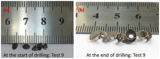
Figure 8.
Chips produced during the experiment at (a) the start of drilling Test 9 and (b) the test cessation of Test 9.
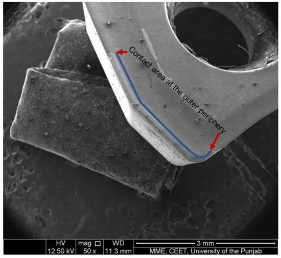
Figure 9.
SEM image of the wiper insert test cessation showing the contact area at the outer periphery.
A bar graph showing the values of tool life is shown in Figure 10. A decline in tool life values with the increase in Vc and f is quite evident. Cutting speed had increased in the generation of higher temperatures, which, in turn, reduced tool life. Escalation in the feed may lead to greater chip thickness and higher mechanical loading on the cutting tool, leading to the shortening of the tool’s life. Error bars show the standard deviation observed in the number of drilled holes. Some variations were observed for Tests 2, 3, and 4, as shown by the standard bars, while no variation occurred in Test 8 during the replications.
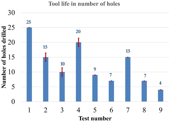
Figure 10.
Tool life with respect to number of holes.
Main effects plots are shown in Figure 11 with a corresponding ANOVA calculations in Table 5. Speed and feed rate are both significant, with percentage contributions (PCR) of 27.48% and 72.10%, respectively.
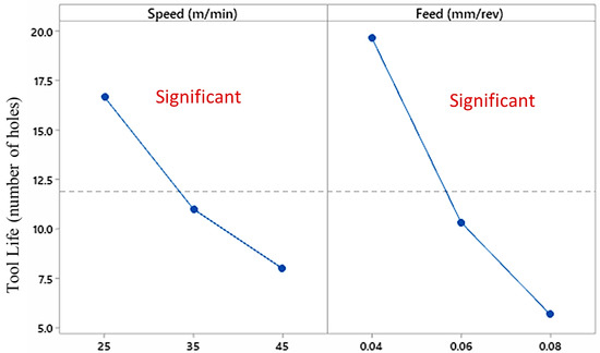
Figure 11.
Main effects plots for tool life.
Table 5.
ANOVA analysis relative to tool life.
Optical micrographs of wear evolution of various tests are shown in Figure 12, Figure 13 and Figure 14. Generally, wear progression is relatively uniform, though evidence of chipping was noticed in some of the tests. It is important to mention that such minor chipping had not affected the tool life, as it occurred within the allowed flank wear criterion. Fractures and significant chipping at the cutting edges and the outer periphery were the commonly reported wear types with the twist drills [3,5,8,29]. Apart from Inconel 718, when TiAlN coated twist drills were evaluated on another nickel alloy such as Hayness 282 or RR 1000, fractures at the outer periphery were encountered, as mentioned by Hood et al. [13] and Soo et al. [14], respectively. These results indicate the susceptibility of twist drills toward fractures in drilling superalloys. The reasons for the better performance of the central and wiper combination compared to twist drills are as follows: (i) The nose radius has a better penetrability compared chisel edge twist drills in extruding the material due to balanced forces as a result of the provision of a positive rake angle. (ii) The fracture and significant chipping of twist drills is a function of the thermal gradient, i.e., zero at the center of the cutting edge and varied to a maximum value at the outer periphery. In the case of the central insert, the temperature is curtailed because the shearing/cutting process is restricted to a certain length due to the provision of the step at the cutting edge (see Figure 1b). Regarding the wiper insert, the temperature is encountered due to the greater contact area of the wiper edge at the outer periphery. Therefore, the central and wiper combination produces lower temperatures than standard twist drills, resulting in longer tool life/less wear.
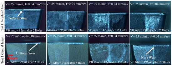
Figure 12.
Wear evolution of central and wiper inserts in Test 1.
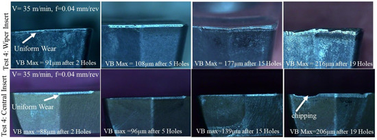
Figure 13.
Wear evolution of central and wiper inserts for Test 4.
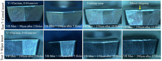
Figure 14.
Wear evolution of Test 7 for central and wiper inserts.
SEM images taken at test termination for Tests 1 (lowest speed/feed), 4 (medium cutting speed/low feed), and 8 (highest cutting speed/feed) are shown in Figure 15, Figure 16 and Figure 17. No formation of built-up edges (BUEs) is seen in the tests, indicating proper shearing of workpiece material in a fully plastic state and suitability of operating parameters. Wear of the central insert is very uniform without any chisel edge wear. In contrast, BUEs, chisel edge wear, and catastrophic fractures were noticed in the drilling of Inconel 718 using a cryogenic environment by Khanna et al. [3] and Shah et al. [29]. Similarly, chisel edge wear was also noticed in ref. [4] as well. Regarding wiper inserts, unevenness is quite apparent along the cutting edge however conventional crater wear is not seen. It is believed that the crater’s formation is due to the flow of the chip over the restricted area. However, in the case of the wiper insert, chip flow is, relatively, over a larger area due to the provision of a straight edge along the nose radius and is termed as blended radii. In Test 9, conducted at the Vc/f combination, minor chipping is evident at the central insert, accompanied by the uniform wear of the wiper insert. A possible reason for the chipping of the central insert at the tool nose is likely due to the greater heat concentration (due to high cutting speed) over the smaller area that, in turn, leads to the generation of high stresses. Chipping while drilling Inconel 718 is commonly reported [2,3,29]. It is important to highlight that such minor chipping would not affect the surface roughness of holes (discussed later in this paper in the surface roughness section).
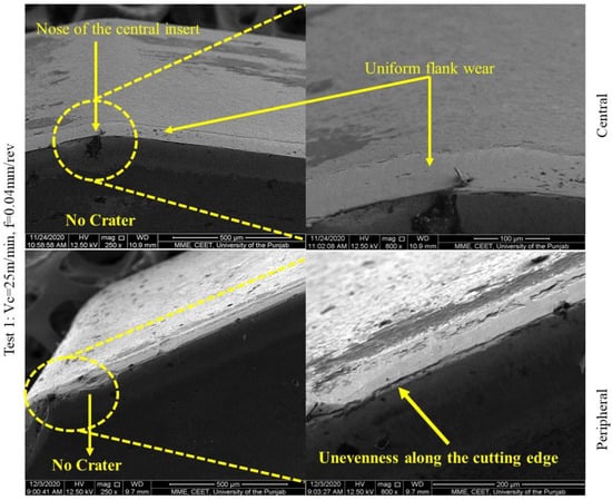
Figure 15.
Wiper and central insert tool wear progression experiment 1.
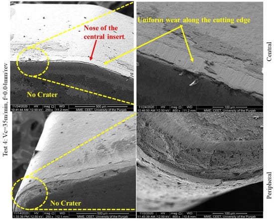
Figure 16.
Wiper and central insert tool wear progression experiment 4.
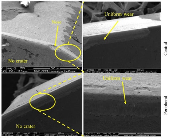
Figure 17.
Wiper and central insert tool wear progression experiment 9.
It is quite apparent that the behavior of carbide inserts has been evaluated in drilling for the first time in this work. However, evaluations of carbide inserts on the nickel alloys included are quite well established. For comparison purposes, some recent state-of-the-art work published in this area is presented. No critical failure was noticed in turning of Inconel 718 and Waspaloy, as observed by Polvorosa et al. [11]. The results are comparable to the current work where no fracture was noticed. Incidentally, notch wear was quite dominant in ref. [11] and on a higher side compared to flank wear while turning Waspaloy and Inconel 718. Suarez et al. [12] claimed that notch wear was much more aggressive in the turning of Hayness 282 compared to other alloys. In contrast to notch formation, flank wear was generally stable and quite predictable for the turning of the nickel based alloys evaluated in refs. [11,12]. Notch wear, which is quite common in cemented carbide inserts, has not been recorded herein in any test, likely due to the novel geometric tool configuration reducing the side flow of the material. As per Valdivielso et al. [27], notch wear can be avoided and surface integrity can be improved by using carbide inserts with a sub-micron grain size. They have provided a systematic surface integrity investigation in the turning of Inconel 718. Interestingly, surface roughness reduction was noticed with the increase in the flank wear up to 200 µm flank wear level. Then, afterward, an increase was observed. This indicates that flank wear level of 200 µm is ideal from surface integrity point of view. Other surface integrity aspects highlighted in ref. [27] including residual stresses, microhardness, and other hole quality attributes will be discussed in our future work.
3.2. Surface Roughness
In general, workpiece surface roughness was less than 1 µm in all tests, irrespective of operating parameters. A 15–25 percent reduction in Ra was noticed with the progression of drilled holes, irrespective of the speed/feed combination, as shown in Figure 18. This is due to the nose radius increase as a result of uniform tool wear. The reduction in the value of surface roughness is quite similar to the reportages of drilling Hayness 282 and RR 1000 [13,14]. For example, a maximum roughness value of 0.93 µm-Ra was recorded at the start of Test 3 (lowest speed/maximum feed), which was reduced to 0.70 µm-Ra at the test’s termination. In Test 7, the roughness was minimum at the start of the test, i.e., with a value of 0.43 µm-Ra and 0.22 µm-Ra at test cessation. In Test 1, where maximum holes (25) were drilled, the roughness was within 0.60 µm to 0.40 µm-Ra. The latter surface roughness values were equivalent to reaming and mill-boring operations; both are considered finishing operations for drilling [5]. It is important to mention that both these tests can be considered important in terms of productivity, drilling 25 and 15 holes, meeting the tight aerospace roughness requirements. Unsurprisingly, the suitable feed rate for all cutting speeds was 0.04 mm/rev compared to 0.06 mm/rev and 0.08 mm/rev with regard to surface roughness, due to greater chip thickness associated with the latter values. The better performance of these inserts over twist drills is due to the production of shorter chips in the drilling process as a result of the restricted involvement of stepped inserts and better chip evacuation, facilitated by the spacious flutes of the tool holder, see Figure 2. On the contrary, in the case of twist drills, longer chips are commonly produced as the whole cutting-edge length is involved in the shearing process. The longer chips become entangled with the drill flutes and rub against the hole walls, which, in turn, deteriorates the hole quality. Sharman et al. [5] noted that the outer periphery of the drilling process is of great concern because the hole walls rub against the drill clearance face and generate maximum temperatures. In this study, the periphery of the hole was cut by a wiper insert that has blended radii adjacent to the nose and a greater contact length (see Figure 1a and Figure 9). This produces a better surface finish and good hole quality with reduced temperature effects in comparison to the twist drill.
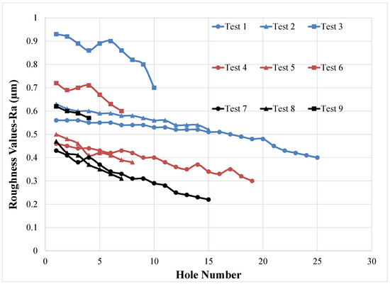
Figure 18.
Roughness values vs. the number of drilled holes.
While contextualizing our findings with the existing literature, a comparison is based on the number of drilled holes and the wear criterion of 200 µm. During the experimentation, Shah et al. [29] used a Vc of 15 m/min, a f of 0.04 mm/rev, and liquid CO2, and achieved a roughness within the range of 0.30–0.40 µm-Ra, which is comparable to Test 7 conducted at a threefold cutting speed. When compared with ref. [8], which conducted drilling in a cryogenic environment at 19 m/min speed and 0.02 mm/rev, Ra was 1.5 µm at the start and 3 µm at the end, which was 3–7 times greater than Test 1 (25 m/min, 0.04 mm/rev) where Ra values were 0.56 to 0.41 µm. Karabul et al. [16] drilled holes in selective laser melted (SLM) Inconel 718 and found roughness values ranging from 1.5–3 µm-Ra with a Vc that ranged within 15–30 m/min, and an f that was 0.025–0.075 mm/rev. Considering this alloy’s application area, the authors in [16] recommended post-finishing as these values were on the higher side. Additionally, compared with current work, these roughness values were substantially higher. In the work of Ucak et al. [8], where TiAlN coated drills were used under wet conditions, the Ra was 1.5 µm at 15 m/min cutting speed and 0.02 mm/rev, which was three times higher compared to Test 1.
Statistically, both speed and feed are significant with new and worn tooling, as shown by the P-Value and PCR% in Table 6. A higher PCR% value of f compared to Vc is due to the direct dependence of roughness on cusp height on the feed rate.
Table 6.
Statistical significance of speed and feed on surface roughness.
3.3. Surface and Subsurface Damage
Surface damage analysis from optical micrographs and SEM images are shown in Figure 19 and Figure 20. Feed marks and the material’s side flow are quite apparent with the new tooling, and surfaces were, relatively, smooth at the last hole. This finding is in line with the previously discussed surface roughness pattern, where Ra values remained lower even with the worn tooling. SEM image analysis also indicates smooth surfaces with worn tooling. The present work does not reveal cavities, material smearing, or grooves commonly observed in references [4,15] while drilling Inconel 718. Material smearing is considered not acceptable in the aerospace industry because it may lead to cavity formation and the fracture of the component [5]. When drilling Hayness and RR 1000, re-deposited material and chip adhesion/adhered material are quite common defects observed by Hood et al. and Soo et al., both with new and worn tools, and became severe at escalated parameters and with worn tools. The absence of such defects clearly indicates the superiority of these tooling over the twist drills. Surface damage was quite severe in the case of the peck drilling strategy, where all defects mentioned above were noticed [4]. Furthermore, even employing pilot holes before drilling [5] was unable to produce the desired quality of drilled hole surfaces compared to those generated with the combination of these central and wiper inserts. Material scratching was observed in some cases with cryogenic machining due to improper chip evacuation and chip entanglement and rubbing with the workpiece during chip evacuation [8]. In this work, due to better chip evacuation and balanced forces due to the central insert, no such case was observed. Another problem that was commonly observed in drilling was the formation of drill caps, specifically at the tool exit [8]; however, this was not seen in the current work (see Figure 21). Furthermore, the burr height at the extreme operating parameters was measured, i.e., the last hole of each experiment where the condition is severe and abusive. The burr heights at the entry and exit were less than 20 µm and 65 µm, respectively, irrespective of the operating parameters. The reduced values of burr height were likely due to optimal tool geometry. Another reason was likely due to better chip evacuation and enhanced shearing action of the inserts. The burr height was considered small compared to the aerospace requirements, as pointed out by Pena et al. [30].
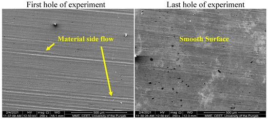
Figure 19.
Surface topography of cross-sectional SEM images of drilled holes of Tests 1 (25 m/min, 0.04 mm/rev).
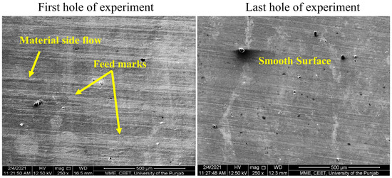
Figure 20.
Surface topography of cross-sectional SEM images of drilled holes of Tests 4 (35 m/min, 0.04 mm/rev).
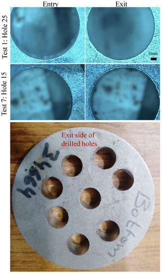
Figure 21.
Images of drilled holes on entry and exit sides for various tests.
The subsurface microstructure (grains) deformation is shown in Figure 22. No significant grains’ distortion/deformation is not observed in any trials for both new and used tools. According to Ucak et al. [8], subsurface deformation is mainly affected by the high temperature and high thrust force. As flood coolant was used in the current study, high temperatures were avoided, and thrust forces were balanced by using the central insert, preventing the grains’ deformation. In previous studies conducted on the drilling of Inconel 718, subsurface plastic deformation was observed in refs. [2,5,8,16,29,31]. Another reason for negligible subsurface microstructural deformation could be the retention/intactness of the cutting edges until the last hole was drilled. Instead of ploughing, shearing took place, which resulted in very little microstructural deformation. Similar results were reported by Eskandri et al. [2], where the cutting edge was intact due to the use of graphene-based cutting fluid, and no sub-surface plastic deformation was seen. It is important to mention that plastic sub-surface deformation observed using a combination of central and wiper inserts were lowerthan the reaming and mill boring of Inconel 718 [5]. The presence of the grain boundaries deformation (up to 15 µm depth) and discontinuous white layer (~6 µm) was observed in the drilling of Haynes 282 [13]; therefore, reaming and mill boring were recommended by the authors for this alloy, as suggested by Sharman et al. [5], in the drilling of Inconel 718. However, in RR1000 drilling, material drag was just 4 µm, and quite a thin white layer was seen. Yet, the latter factor increased to 90% when drilling in dry mode, supplementing the authors’ claim that the drilling of nickel alloys without cutting fluid is not feasible.
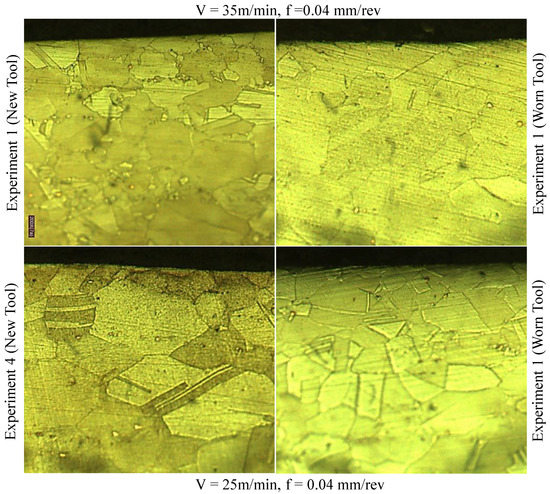
Figure 22.
Microstructure images of the cross-section beneath the hole surface.
4. Conclusions and Future Research
In this study, Inconel 718 was drilled via a combination of stepped and wiper inserts in the presence of cutting fluid. The main conclusions drawn from the current investigation were as follows:
- Dry machining of nickel-based superalloys is generally not feasible irrespective of the machining process. Even with newly developed inserts, a catastrophic fracture was observed when dry drilling was used for Inconel 718.
- With uniform tool wear, the maximum tool life in terms of drilled holes was achieved at a 25 m/min Vc and 0.04 mm/rev f, with roughness values (Ra) ranging from 0.60 µm to 0.40 µm. Contrary to previous studies and in terms of productivity, almost 3-fold more holes (15 holes) were drilled when the cutting speed was escalated to 45 m/min, with impressing surface roughness ranging from 0.43 µm-Ra to 0.22 µm-Ra.
- The better performance of the central insert compared to the twist drill was due to the provision of the nose radius and steps at both ends; the latter factor was responsible for shorter chips, the evacuation of which was relatively easier compared to the longer chips. Additionally, the sweeping action of the wiper insert improved the surface finish by reducing the cusps height of the machined surface.
- The SEM images showed no evidence of BUEs and crater formation, indicating that the operating parameters were suitable.
- Surface defects, including re-deposited material and chip adhering, were not observed, with negligible plastic sub-surface deformation. Surface roughness was equivalent to finishing operations, eliminating the need for post-machining operations. Therefore, this drilling process was termed as the one-step finish drilling of Inconel 718.
- The main limitation of this work is that it was performed in the presence of cutting fluid, which is unfavorable to the environment and worker health, and escalates the machining cost.
- In future work, various novel coatings could be evaluated while taking care of the droplet elimination from the coating surface to improve the coatings’ performance. There is a need to assess the new central and wiper inserts combination in cryogenic and MQL environments. More surface integrity attributes, such as residual stresses and microhardness, need to be evaluated. Moreover, optimizing drilling process parameters using various approaches (Desirability, ANFIS) should also be considered.
Author Contributions
S.A.: Data curation, validation, writing—original draft, and writing—review and editing; N.A.K.: Data curation, Investigation, Methodology, Visualization, and writing—original draft; S.A.K.: Conceptualization, Investigation, Methodology, Supervision, writing—original draft, and writing—review and editing. S.F.R.: Methodology. All authors have read and agreed to the published version of the manuscript.
Funding
The authors appreciate the support from Researchers Supporting Project number (RSPD2023R702), King Saud University, Riyadh, Saudi Arabia.
Data Availability Statement
The data presented in this study are available on request from the corresponding author.
Acknowledgments
The authors appreciate the support from Researchers Supporting Project, number (RSPD2023R702), King Saud University, Riyadh, Saudi Arabia.
Conflicts of Interest
The authors declare no conflict of interest.
References
- Pang, K.; Wang, D. Study on the performances of the drilling process of nickel-based superalloy Inconel 718 with differently micro-textured drilling tools. Int. J. Mech. Sci. 2020, 180, 105658. [Google Scholar] [CrossRef]
- Eskandari, B.; Bhowmick, S.; Alpas, A.T. Flooded drilling of Inconel 718 using graphene incorporating cutting fluid. Int. J. Adv. Manuf. Technol. 2021, 112, 1–14. [Google Scholar] [CrossRef]
- Khanna, N.; Agrawal, C.; Gupta, M.K.; Song, Q. Tool wear and hole quality evaluation in cryogenic Drilling of Inconel 718 superalloy. Tribol. Int. 2020, 143, 106084. [Google Scholar] [CrossRef]
- Qin, X.; Liu, W.; Li, S.; Tong, W.; Ji, X.; Meng, F.; Liu, J.; Zhao, E. A comparative study between internal spray cooling and conventional external cooling in drilling of Inconel 718. Int. J. Adv. Manuf. Technol. 2019, 104, 4581–4592. [Google Scholar] [CrossRef]
- Sharman, A.R.C.; Amarasinghe, A.; Ridgway, K. Tool life and surface integrity aspects when drilling and hole making in Inconel 718. J. Mater. Process. Technol. 2008, 200, 424–432. [Google Scholar] [CrossRef]
- Shah, P.; Bhat, P.; Khanna, N. Life cycle assessment of drilling Inconel 718 using cryogenic cutting fluids while considering sustainability parameters. Sustain. Energy Technol. Assess. 2021, 43, 100950. [Google Scholar] [CrossRef]
- Girinon, M.; Dumont, F.; Valiorgue, F.; Rech, J.; Feulvarch, E.; Lefebvre, F.; Karaouni, H.; Jourden, E. Influence of lubrication modes on residual stresses generation in drilling of 316L, 15–5PH and Inconel 718 alloys. Procedia CIRP 2018, 71, 41–46. [Google Scholar] [CrossRef]
- Uçak, N.; Çiçek, A. The effects of cutting conditions on cutting temperature and hole quality in drilling of Inconel 718 using solid carbide drills. J. Manuf. Process. 2018, 31, 662–673. [Google Scholar] [CrossRef]
- Amigo, F.J.; Urbikain, G.; Pereira, O.; Fernández-Lucio, P.; Fernández-Valdivielso, A.; de Lacalle, L.N.L. Combination of high feed turning with cryogenic cooling on Haynes 263 and Inconel 718 superalloys. J. Manuf. Process. 2020, 58, 208–222. [Google Scholar] [CrossRef]
- Pereira, O.; Celaya, A.; Urbikaín, G.; Rodríguez, A.; Fernández-Valdivielso, A.; Noberto López de Lacalle, L. CO2 cryogenic milling of Inconel 718: Cutting forces and tool wear. J. Mater. Res. Technol. 2020, 9, 8459–8468. [Google Scholar] [CrossRef]
- Polvorosa, R.; Suárez, A.; de Lacalle, L.N.L.; Cerrillo, I.; Wretland, A.; Veiga, F. Tool wear on nickel alloys with different coolant pressures: Comparison of Alloy 718 and Waspaloy. J. Manuf. Process. 2017, 26, 44–56. [Google Scholar] [CrossRef]
- Suárez, A.; Veiga, F.; de Lacalle, L.N.L.; Polvorosa, R.; Wretland, A. An investigation of cutting forces and tool wear in turning of Haynes 282. J. Manuf. Process. 2019, 37, 529–540. [Google Scholar] [CrossRef]
- Hood, R.; Soo, S.L.; Aspinwall, D.K.; Andrews, P.; Sage, C. Twist drilling of haynes 282 superalloy. Procedia Eng. 2011, 19, 150–155. [Google Scholar] [CrossRef]
- Soo, S.L.; Hood, R.; Aspinwall, D.K.; Voice, W.E.; Sage, C. Machinability and surface integrity of RR1000 nickel based superalloy. CIRP Ann.—Manuf. Technol. 2011, 60, 89–92. [Google Scholar] [CrossRef]
- Rahim, E.A.; Sasahara, H. An analysis of surface integrity when drilling inconel 718 using palm oil and synthetic ester under MQL condition. Mach. Sci. Technol. 2011, 15, 76–90. [Google Scholar] [CrossRef]
- Karabulut, Y.; Kaynak, Y. Drilling process and resulting surface properties of Inconel 718 alloy fabricated by Selective Laser Melting Additive Manufacturing. Procedia CIRP 2020, 87, 355–359. [Google Scholar] [CrossRef]
- Beer, N.; Özkaya, E.; Biermann, D. New production technologies in aerospace industry—5th machining innovations conference (MIC 2014) drilling of inconel 718 with geometry-modified twist drills. Procedia CIRP 2014, 24, 49–55. [Google Scholar] [CrossRef]
- Iovkov, I.; Bücker, M.; Biermann, D. A modified tool design for the drilling of high-performance aerospace materials. CIRP Ann. 2021, 70, 10–13. [Google Scholar] [CrossRef]
- Biermann, D.; Bücker, M.; Tiffe, M.; Özkaya, E. Experimental investigations for a simulative optimization of the cutting edge design of twist drills used in the machining of Inconel 718. Procedia Manuf. 2017, 14, 8–16. [Google Scholar] [CrossRef]
- Vrabeľ, M.; Eckstein, M.; Maňková, I. Analysis of the metallography parameters and residual stress induced when producing bolt holes in Inconel 718 alloy. Int. J. Adv. Manuf. Technol. 2018, 96, 4353–4366. [Google Scholar] [CrossRef]
- Liu, Y.; Zhang, D.; Geng, D.; Shao, Z.; Zhou, Z.; Sun, Z.; Jiang, Y.; Jiang, X. Ironing effect on surface integrity and fatigue behavior during ultrasonic peening drilling of Ti-6Al-4 V. Chin. J. Aeronaut. 2022. [Google Scholar] [CrossRef]
- Yin, X.; Li, X.; Liu, Y.; Geng, D.; Zhang, D. Surface integrity and fatigue life of Inconel 718 by ultrasonic peening milling. J. Mater. Res. Technol. 2023, 22, 1392–1409. [Google Scholar] [CrossRef]
- Ali, S.; Umar, M.; Qaiser, M.; Ahmad, N. Experimental investigations on wiper inserts’ edge preparation, workpiece hardness and operating parameters in hard turning of AISI D2 steel. J. Manuf. Process. 2018, 34, 187–196. [Google Scholar] [CrossRef]
- Di Crescenzo, A.D.; Mousseigne, M.; Rubio, W. Effect on surface integrity of high-productivity finishing on Ti-6Al-4V with wiper edge length tool. Procedia CIRP 2022, 108, 406–411. [Google Scholar] [CrossRef]
- Khan, S.A.; Ahmad, M.A.; Saleem, M.Q.; Ghulam, Z.; Qureshi, M.A. High-feed turning of AISI D2 tool steel using multi- radii tool inserts: Tool life, material removed, and workpiece surface integrity evaluation. Mater. Manuf. Process. 2017, 32, 670–677. [Google Scholar] [CrossRef]
- Rodríguez-Barrero, S.; Fernández-Larrinoa, J.; Azkona, I.; López De Lacalle, L.N.; Polvorosa, R. Enhanced Performance of Nanostructured Coatings for Drilling by Droplet Elimination. Mater. Manuf. Process. 2016, 31, 593–602. [Google Scholar] [CrossRef]
- Fernández-Valdivielso, A.; López De Lacalle, L.N.; Urbikain, G.; Rodriguez, A. Detecting the key geometrical features and grades of carbide inserts for the turning of nickel-based alloys concerning surface integrity. Proc. Inst. Mech. Eng. Part C J. Mech. Eng. Sci. 2016, 230, 3725–3742. [Google Scholar] [CrossRef]
- Suárez, A.; Veiga, F.; de Lacalle, L.N.L.; Polvorosa, R.; Lutze, S.; Wretland, A. Effects of Ultrasonics-Assisted Face Milling on Surface Integrity and Fatigue Life of Ni-Alloy 718. J. Mater. Eng. Perform. 2016, 25, 5076–5086. [Google Scholar] [CrossRef]
- Shah, P.; Bhat, P.; Khanna, N. Comparison of LCO 2 and LN 2 Based on Machining Performance and Life Cycle Assessment for Inconel 718 Drilling. J. Manuf. Process. 2022, 81, 444–466. [Google Scholar] [CrossRef]
- Peña, B.; Aramendi, G.; Rivero, A.; De Lacalle, L.N.L. Monitoring of drilling for burr detection using spindle torque. Int. J. Mach. Tools Manuf. 2005, 45, 1614–1621. [Google Scholar] [CrossRef]
- Azim, S.; Gangopadhyay, S.; Mahapatra, S.S.; Mittal, R.K.; Singh, A.; Singh, R.K. Study of cutting forces and surface integrity in micro drilling of a Ni-based superalloy. J. Manuf. Process. 2019, 45, 368–378. [Google Scholar] [CrossRef]


Disclaimer/Publisher’s Note: The statements, opinions and data contained in all publications are solely those of the individual author(s) and contributor(s) and not of MDPI and/or the editor(s). MDPI and/or the editor(s) disclaim responsibility for any injury to people or property resulting from any ideas, methods, instructions or products referred to in the content. |
© 2023 by the authors. Licensee MDPI, Basel, Switzerland. This article is an open access article distributed under the terms and conditions of the Creative Commons Attribution (CC BY) license (https://creativecommons.org/licenses/by/4.0/).