Abstract
To enhance the deflagration efficiency and protection level of combustible mixed gases in narrow spaces, a small square experimental pipeline system was designed. Experiments were conducted to investigate the effects of lateral vent pipes and metal wire meshes on the explosion characteristics of methane gas. This study examined the influence of changing the positions of the lateral vent pipes and metal wire meshes in the pipeline on the variation of parameters such as the flame shape, leading speed, and pressure of the methane/air premixed gas in the pipeline. The results indicated that the lateral vent pipes could effectively release part of the energy from the methane explosion, and the release effect was stronger the closer they were to the ignition end. This was significantly more effective in releasing the flame and pressure than when the vent pipes were placed in the middle or at the end of the pipeline. For lateral vent pipes close to the ignition source, their effective release of the not yet fully developed premixed flame allowed the heat absorption, wave absorption, and quenching performance of the installed metal wire mesh in the pipeline to fully exert their effects on the slow-spreading premixed flame. Furthermore, when a metal mesh was installed in the pipeline and the flame could not be extinguished, the flame penetrated the mesh structure, causing the flame front to become unstable and exhibit “irregular wrinkles”. That is, the flame front was no longer smooth, the wrinkles became more pronounced, and the degree of turbulence was enhanced.
1. Introduction
With the widespread use of natural gas as a clean energy source, the issue of leakage during its pipeline transportation process has become a focal point for researchers. Due to natural factors and human interference, natural gas may leak into narrow spaces such as pipeline corridors and tunnels. In the presence of an ignition source, this can easily trigger an explosion, causing significant damage and harm to society [1,2,3]. Therefore, research on explosion protection technology for natural gas pipeline corridors is of great significance in preventing potential explosion accidents in natural gas pipeline corridors.
After an explosion occurs, various explosion protection measures, such as explosion suppression, explosion isolation, and explosion venting, are commonly employed to mitigate the damage caused by the explosion [4,5,6,7,8,9,10,11,12,13,14]. Examples of these measures include porous media [5,6], water mist [7,8,9], explosion relief valves, and explosion vent panels [10,11,12,13,14]. Because of its good mitigating effects and ease of implementation, explosion venting is widely used, and many influence factors on explosion venting have been studied. Rocourt et al. [15] studied the effect of five different vent sizes on explosions inside cubic chambers and explained the mechanism by which vent size affects the peak pressure. Xing et al. [16] investigated the effects of pipeline explosion vent closure and changes in vent area and found that smaller vent areas resulted in higher peak pressures during venting. Zhao et al. [17] found that different venting positions and intensities can change the explosion characteristics of methane through the study of chamber length and venting conditions. Moreover, the maximum overpressure increases with the increase in chamber length and then decays. Ajrash et al. [18,19] studied a side vent of a 30 m pipeline, finding that at distances ranging from 6.5 to 20.5 m from the ignition source, the vent reduced the explosion pressure by 33% to 56%. Wan et al. [20,21,22,23] conducted separate studies investigating the influence of the lateral venting port position, area, and pipeline blockage rate on the explosion characteristics of methane mixed gas. They also analyzed the blast-resistant properties and mechanisms associated with these factors. Duan et al. [24,25,26] found that porous media of different pore sizes and thicknesses in pipelines can suppress the propagation of explosion flames, but large pore sizes can cause explosion deflagration. Lv et al. [27] studied the effect of the opening pressure of the vertical branch pipe explosion vent on the deflagration characteristics of methane at different concentrations. They found that the vertical branch pipe reduced the peak explosion pressure, and had both a “promoting” and “inhibiting” effect on the propagation speed of the flame. Jin et al. [28,29,30,31] analyzed the effect of metal wire mesh on pipeline flame shape and pressure kinetics and found that metal wire mesh has a significant inhibitory effect on pressure waves and combustion processes. Cao et al. [32,33] studied the impact of metal wire mesh structural parameters and heat resistance on synthetic gas explosions and found that increasing the number and layers of metal wire mesh can effectively reduce the explosive intensity. Feng et al. [34], through their experiments on the suppression of methane flame propagation characteristics by various layers of metal mesh, believe that the suppressive effect of metal mesh is a reflection of the coupled behavior of explosive flame propagation within the pipe and burning conditions. Wu et al. [35] investigated the laws of flame propagation under the inhibitory effect of porous media. They found that the sidewall lining of porous media had a certain explosion suppression effect. The quenching efficiency of media with smaller PPIs (pores per inch) was not significant. With constant PPIs, as the thickness of the media increased, the explosion suppression efficiency significantly improved.
The response capacity and suppression effect of a single type of venting or blast mitigation measure have certain limitations. Current research is dedicated to effectively combining different explosion suppression techniques. Zhang et al. [36] conducted a series of experiments to study the suppression effect of metal mesh structures on methane explosions in interconnected pipes, analyzing the explosion suppression effect of metal meshes with different parameters. Five and seven are the critical explosion suppression layers for 40-mesh and 60-mesh metal meshes, respectively. Compared with the five-layer 40-mesh metal mesh structure, the seven-layer 60-mesh metal mesh structure has a better explosion suppression effect. Cui et al. [37] conducted experimental research on the dual suppression effect of the metal mesh and the spherical container interconnected pipeline on methane explosions, finding that the effectiveness of explosion suppression mainly depends on the number of layers and grids. Wang et al. [38] explored the mitigating effect of a metal mesh on the jet flame emerging from explosion venting, finding that as the number of metal mesh layers increases, the flame propagation speed and pressure noticeably reduce. As the distance from the metal mesh to the explosion venting point increases, the peak temperature initially rises before decreasing, whilst the maximum explosion pressure first reduces and then rises. Lu et al. [39] studied methane explosions inside spherical containers equipped with metal wire mesh and conduits. They found that as the number of wire mesh layers, the quantity of wire meshes, and the venting diameter increased, the degree to which the flame leaked outside the container gradually weakened, and the maximum pressure inside the container decreased. Wang et al. [40] investigated the role of side exhaust holes and metal wire mesh in suppressing methane explosions. The results showed that side exhaust holes and metal wire mesh complementarily suppress the flames, while the effect of metal wire mesh combined with side venting on high-speed turbulent flames is relatively poor. Further research is needed on how to effectively use venting conduits and metal mesh to reduce the intensity of gas explosions.
Based on this, a small-scale experimental pipeline was used to simulate urban underground pipe galleries, lateral explosion relief conduits were installed at three different locations on the pipeline wall, and metal wire meshes with the same parameters were placed at two different positions inside the pipeline. By changing the positions of the lateral conduits and the metal wire mesh, the propagation form, front speed, and pressure characteristics of the flame of the premixed methane/air gas explosion in the square pipe were studied, with the aim of providing a reference for the explosion safety of the natural gas pipe gallery.
2. Experimental System and Methods
2.1. Experimental Apparatus and Testing Instruments
The gas explosion system used in this experiment is shown in Figure 1, consisting of a transparent acrylic square pipe (PMMA), a gas distribution system, a pulsed ignition device, a high-speed camera, and an explosion pressure acquisition system.
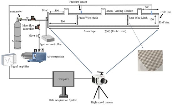
Figure 1.
Schematic diagram of the experimental system.
The pipe is composed of three sections of acrylic square tubes connected by flanges, with a total length of 2000 mm, a cross-sectional size of 150 mm × 150 mm, and a wall thickness of 20 mm. The left end is sealed with an acrylic blind plate, on which an air inlet/outlet valve and an ignition electrode are installed. The right end is open to vent explosions and ensure experimental safety. The gas distribution system includes a vacuum pump, a gas mass flow meter, and methane gas cylinders. The gas mass flow controller, model ALICAT (0~5 SLPM, ±1.0% F.S), controls the gas input flow rate. The pulsed ignition device was installed at the center of the acrylic blind plate at the left end of the pipeline. It is a self-made GNQ-05 model from Xi’an Kehui Thermal Engineering Technology Design Research Institute (Xi’an, China), with an ignition energy of 10 J. The high-speed camera used was the PHANTOM V1212-72G-C model (Vision Research, Inc., Wayne, NJ, USA), with a maximum shooting speed of 550,000 frames per second. In this experiment, a rate of 1000 frames per second was used, with a maximum resolution of 1200 × 800 pixels. The explosion pressure acquisition system consists of PCB 113A21 (PCB Piezotronics Technology (Beijing) Co., Ltd., Beijing, China) series piezoelectric pressure sensors, signal amplifiers, and a four-channel data acquisition card. The pressure sensor has a measurement range of 0 to 1.38 MPa. Two pressure sensors were installed on the side walls of the pipe at positions 600 mm and 1900 mm.
2.2. Experimental Methodology
Single conduits were set up on the side of the square tube at distances of 300 mm, 1000 mm, and 1700 mm from the closed end on the left, referred to as Conduit 1, Conduit 2, and Conduit 3, respectively. The length-to-diameter ratio of the conduits was 100 × 60 mm. Additionally, for each experiment, a 30-mesh TP304 stainless steel square wire mesh (one-layer) was installed at a distance of 500 mm (front section) or 1500 mm (rear section) from the left end of the pipe. The parameters of the metal mesh are presented in Table 1. The experimental conditions are shown in Table 2.

Table 1.
Properties of wire mesh types used in the tests.
Table 2.
The settings of experimental conditions.
During the experiment, the right end of the main pipe and the interface between the pipe and the venting conduit were sealed with PVC film. A certain volume of air was extracted using a vacuum pump, followed by injection of methane through a methane gas (methane volume fraction of 99.99%) cylinder and a mass flow meter. Finally, air was supplemented through the inlet hole at the left end of the pipe, resulting in a methane/air mixture with a volumetric concentration of 9.5% (stoichiometric) inside the pipe. The experimental conditions were set at 293 K (20 °C) and 0.1 MPa. After the gas distribution was complete, the ignition device was activated to ignite the mixture, while simultaneously capturing the dynamic process of explosion flame propagation and collecting pressure signals.
3. Results and Discussion
3.1. Analysis of Methane Explosion Flame Characteristics under Different Positions of Lateral Conduits
Figure 2 shows an image of flame propagation along the pipeline. In Figure 2a, after ignition, due to the restriction of the left end wall of the pipeline, the flame expands in a hemispherical shape, and then, limited by the smooth wall of the pipeline, it transforms into a finger-shaped flame at around 75 ms and continues to propagate along the pipeline. At around 155 ms, the flame propagates to the middle of the pipeline, and at t = 251 ms, the flame reaches the end vent.
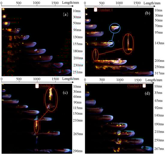
Figure 2.
Comparison of the flame of the side conduit at different positions of the pipeline: (a) flame image without lateral conduit; (b) flame image with lateral conduit in position 1; (c) flame image with lateral conduit in position 2; (d) flame image with lateral conduit in position 3.
Figure 2b shows the flame propagation image under the condition of Conduit 1’s lateral setup. The flame front reaches the lower part of Conduit 1 at t = 70 ms, but the flame does not immediately release through the lateral conduit. Instead, it continues to propagate along the conduit for some time and only starts to release through the conduit at approximately t = 136 ms. Subsequently, a large amount of flame propagates through the conduit to the outside, as indicated by the red box in the figure. After the flame release, the subsequent propagation time is significantly prolonged, and it is not until t = 317 ms that the flame is released out of the conduit through the terminal explosion relief port. The delay in flame venting is attributed to the combined effect of the lateral propagation dynamics of the flame and the induced action of the end vent when the flame just reaches the position directly below the lateral guide tube. The flame continues to propagate in the downstream direction of the tube, and afterward, due to the change in pressure difference inside and outside the tube (with higher internal pressure), part of the flame flows in the opposite direction after passing the position below the lateral guide tube, venting outward from the lateral guide tube. In a short period, the inertia of lateral propagation is significant, and therefore, the pressure difference between the inside and outside of the conduit in the longitudinal direction is insufficient to draw the flame from the downstream direction of the conduit to the explosion relief conduit.
Under the venting effect of the lateral conduit, a long-stretched flame front appears (as shown in the blue box), which gradually tilts and attaches to the upper wall of the pipeline. The appearance of the stretched flame is due to the continuous venting effect of the conduit, which causes the flame to carry some of the fuel released to the outside of the pipeline, resulting in a longitudinal concentration gradient of methane/air–premixed gas inside the pipeline. In addition, the induced venting force at the end vent of the pipeline can cause unstable gas flow and heat exchange; according to the theory of Helmholtz instability [23], the flame front tilts and is then stretched. The vented flame from the explosion conduit, as shown in the two red boxes in Figure 2, is irregular in shape and bursts out of the conduit in the form of a jet flame. The venting process, which results in the release of partially combusted fuel, causes the methane flame at the conduit to be in a lean combustion state, and it exhibits a bright yellow color.
In Figure 2d, lateral Conduit 3 was installed with a venting port, but no flame was vented out from it. This is because lateral Conduit 3 was located near the end vent, and the venting effect at the end is stronger than the lateral venting effect, so the flame was quickly guided and released out from the end vent. Comparing the time required for the flame to propagate to the end vent under the lateral conduit conditions and the condition without conduits, the propagation times for lateral conduits 1, 2, and 3 were 317 ms, 296 ms, and 267 ms, respectively. The elongation ratios were 26.29, 17.92, and 6.37%, respectively.
3.2. Methane Explosion Flame Propagation Velocity in Different Lateral Conduits
Figure 3 presents a flame propagation velocity–time diagram for different lateral conduit conditions. The flame’s instantaneous propagation velocity was obtained by dividing the distance traveled within a unit of time by the corresponding elapsed time. This was achieved by taking the average velocity between two consecutive images as the instantaneous velocity for the subsequent image. Consequently, a curve representing the variation of the flame front velocity concerning time was derived.
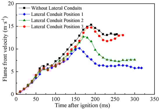
Figure 3.
Flame velocity diagram of lateral conduit blasting conditions at different positions.
From the graph, it can be observed that the flame velocity exhibits similar changes. Initially, it accelerates along the conduit, followed by a brief deceleration, and then accelerates again to reach a peak before gradually slowing down, with a slight subsequent acceleration. After the ignition of the methane/air–premixed gas inside the conduit, the gas starts to burn and self-accelerate. Around 60–70 ms, a brief speed decrease occurs, which can be attributed to the flame encountering wall constraints during its development. According to the wall effect and cold-wall extinction criteria [25,26], the reduction in the flame surface area upon contact with the sidewall leads to energy loss and directly causes a deceleration of the flame front velocity. As combustion continues, the released heat rapidly increases the gas temperature and expands its volume, resulting in an increase in internal conduit pressure due to pressure waves and chemical reactions within the gas, leading to a peak in flame acceleration. Subsequently, as the combustion products do not continue expanding within finite time and space, the reaction gradually completes. Additionally, factors such as wall effects and end venting further contribute to the decrease in flame propagation velocity.
In the absence of lateral venting conduits, the flame propagation velocity reaches its peak at t = 180 ms, measuring approximately 15.2 m/s. In condition 1, the flame propagation velocity first peaks around t = 150 ms, reaching approximately 10.3 m/s, then decreases and reaches the end vent with a lower velocity after t = 210 ms. In condition 2, the flame velocity peaks at t = 174 ms, measuring approximately 12.7 m/s. The velocity curve in condition 3 is similar to that for the scenario without lateral venting conduits. This is because the lateral conduit in position 3 is located close to the end vent, resulting in minimal influence on flame propagation.
3.3. Analysis of Overpressure Resulting from Methane Explosions in Different Lateral Conduit Positions
Figure 4 presents a comparative graph of overpressure curves in the pipeline under different operating conditions with changes in the position of the lateral conduit. In Figure 4, the pressure data from Sensor 1 are referred to as the front overpressure, the pressure curve from Sensor 2 is referred to as the rear overpressure, and the maximum value reached in the overpressure history is defined as the maximum overpressure (pmax). The overpressure curve trends for several operating conditions are consistent, and the trends presented by the overpressure align with the changes in the flame tip speed. In the initial stage of the explosion, the premixed gas is ignited, resulting in relatively low overpressure. As the explosion progresses, the overpressure in the pipeline sharply rises with the expansion of the explosion products, and around t = 60 ms after ignition, all overpressure curves exhibit a brief drop–rise. This is due to the high temperature and pressure generated at the moment of flame ignition, causing the premixed gas to form a precursor pressure wave due to compression disturbance [21,22]. The precursor wave propagates to the end and breaks through the explosion venting film, releasing part of the overpressure into the open space outside the pipeline, causing a brief drop in overpressure inside the pipeline. Subsequently, the combustion products behind the flame front continue to expand, and the resulting piston effect compresses the unreacted gas in front, forming a compression wave and continuously pushing the flame forward. The flame accelerates to reach its peak, and the acceleration state involves the unburned gas in the reaction. The continuous combustion and energy release of the methane/air–premixed gas cause the pressure to continuously rise, resulting in the peak overpressure (pmax), and the flame propagates to the rear end of the pipeline. In the later stage of flame propagation, the rate of overpressure generation is lower than the rate of overpressure release, and the overpressure gradually decreases.
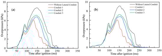
Figure 4.
Overpressure–time diagrams of lateral blowdown conduits at different positions: (a) front overpressure; (b) back overpressure.
The figure shows that there is not much difference between the front and rear overpressure curves, which indicates that the pressure at different locations in the small-sized pipe used in this experiment varies slightly, and pressure propagation is very rapid. Thus, the overpressure at different locations is basically the same. In fact, however, the explosion overpressure at different positions in the pipe is not exactly the same. This is due to the impact of explosion relief ducts at different positions and the end relief port on the release of overpressure, so the overpressure size at different positions will not be exactly the same. The peak overpressure values of different working conditions in the curves of rear overpressure in Figure 4b are as follows: 9.195 kPa, 6.127 kPa, 6.861 kPa, 7.305 kPa. By comparing the peak overpressure values of different working conditions, it can be seen that the overpressure of the lateral relief duct working conditions is significantly lower than that of the working conditions without the lateral relief duct, decreasing by 33.38%, 25.41%, and 20.059%, respectively.
3.4. Analysis of Flame Propagation in Conjunction with a Lateral Conduit and an Internal Metal Mesh in the Pipeline
Figure 5 illustrates the propagation of an explosion flame along a pipeline when a side relief duct is installed in position 1 under different conditions of metal mesh placement. In the scenario depicted in Figure 5a, where the metal mesh is located at the front of the position 1 lateral vent pipe, the flame reaches the metal mesh in 89 ms and pauses for 2–3 ms. When the flame front makes contact with the metal mesh, the free radicals (reactive molecules) produced by the explosive reaction collide with the porous metal mesh [29,30], leading to a higher rate of free radical destruction than production. However, due to the metal mesh’s insufficient capacity to consume a large number of molecules with free bonds, there is a brief increase in the concentrations of H, O, OH, and other free radicals [32]. This results in a slight increase in the flame’s combustion rate and heat release rate. The overall heat loss remains less than the heat released by combustion, and is insufficient to disrupt the chain reaction process of combustion [33]. Consequently, the flame only briefly stagnates at the metal mesh.
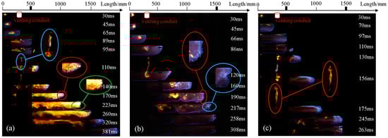
Figure 5.
Flame shape diagram under operating conditions in metal mesh within pipeline in coordination with side venting duct in position 1: (a) flame image with lateral Conduit 1 and front metal mesh; (b) flame image with lateral Conduit 1 and rear metal mesh; (c) flame image with lateral Conduit 1 and front and rear metal mesh.
Subsequently, the unquenched laminar flame penetrates the metal wire mesh, becoming segmented into small jet flames by the mesh structure. Simultaneously, the flame begins to vent through the position 1 lateral blowout guide pipe (as shown by the flame venting in the blue box in Figure 5a). At t = 140 ms and t = 170 ms, the continuous venting effect is clearly observable, causing the flame front to present a honeycomb-like wrinkling and an upward slant along the upper wall (as shown in the red box in Figure 5a). The continuous venting action of the lateral guide pipe puts the pipeline in a high-pressure unstable state. At the same time, the flame that penetrates the metal mesh and propagates downstream is induced to flow towards the lateral guide pipe and contacts the metal mesh again. The temperature difference between the flame and the metal wire leads to secondary heat transfer, causing energy attenuation. The combined effects of the metal mesh and the guide pipe-induced flow alter the internal flow field of the pipeline, thereby affecting the front edge structure and propagation speed of the flame after it passes through the mesh. Subsequently, the slanted front end of the flame decelerates, and at t = 223 ms, the slanted front becomes flat (as shown in the green box in Figure 5a). Finally, at 381 ms, the flame propagates to the end blowout vent for release.
In Figure 5b, the experimental condition of a single rear metal wire mesh in the pipeline is shown. Due to the lack of obstruction in the early stages of development, the flame begins to vent through the No. 1 lateral guide pipe at approximately 82 ms. After a period of continuous venting, heat loss occurs, and the flame inside the pipe becomes relatively weak. At 160 ms, the flame front exhibits irregular wrinkling (as shown in the red box in Figure 5b). After the flame propagates a certain distance, at approximately 217 ms, the flame front reverses, and the flame shape slightly concaves (as shown in the blue box in Figure 5b). Ultimately, the flame, with its concave front, contacts the metal wire mesh and is quenched at t = 258 ms, with no further flame propagation to the end blowout vent.
In Figure 5c, the rear metal wire mesh also successfully quenches the flame vented through the lateral blowout guide pipe. The difference is that due to the shock absorption effect of the rear metal wire mesh and the venting action of the lateral blowout guide pipe, the excitation effect of the front metal wire mesh on the flame decreases under this condition. The flame does not reach an intense combustion state and contacts the rear metal wire mesh at approximately 245 ms, after which the flame is successfully quenched. Compared to Figure 5a, although the continuous venting action of the lateral blowout guide pipe greatly slows down the propagation speed of the turbulent flame redeveloping after penetrating the front metal mesh, the lateral guide pipe brings in fresh external air into the pipeline while recirculating the flame. The shock wave generated by the flame excited by the front metal mesh propagates directly to the end blowout vent without the shock absorption of the rear metal wire mesh. Hence, combustion is still sufficient, and the effect is still stronger than the condition without the rear metal mesh.
3.5. Analysis of Flame Velocity in Lateral Conduit with Collaborative Internal Metal Mesh during Methane Explosion
Figure 6 presents a flame propagation speed–time graph for several metal mesh placement scenarios. The propagation in the single rear metal mesh scenario is similar to that in a pipeline with only a side relief duct installed. The difference is that the presence of the rear metal mesh can reduce the flame propagation speed in the latter part of the pipeline and successfully extinguish the flame. The premixed flame moves downstream along the pipeline. Due to the presence of a metal mesh in the middle and rear sections of the pipeline, flow resistance is formed in the unburned area, thereby generating a reactive force that inhibits flame propagation. Meanwhile, as the flame continues to vent through the side duct, the flame and fuel inside the pipeline become very diluted, fully utilizing the quenching performance of the metal mesh, i.e., the flame’s speed drops to 0 m/s when it propagates to 1500 mm in the pipeline.
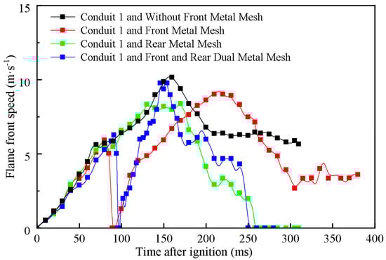
Figure 6.
Velocity diagram of the flame front under operating conditions in metal mesh within the pipeline in coordination with the side venting duct in position 1.
The velocity profiles of the two conditions where metal wire mesh is present at the front of the pipeline have certain similarities. Initially, the speed increases as the flame begins to propagate. When the flame reaches the position of the front metal mesh, its speed rapidly drops to 0 m/s. As can be seen in the flame images in Figure 5a,c, the flame experiences a brief stall, after which the methane/air–premixed gas reignites behind the mesh. After the flame passes through the metal wire mesh, it re-accelerates, with the tip speed sharply increasing in an exponential form before gradually decreasing. The velocity under the condition of the front metal mesh reaches its peak at t = 209 ms, with a magnitude of 9.305 m/s. Under the condition of the double metal mesh (front and rear), the velocity peaks at 10.164 m/s at t = 152 ms. The difference lies in that after reaching the peak speed in the single front metal mesh condition, the speed drops to a certain extent and maintains a low speed through the end blowout vent. In contrast, in the case of both front and rear metal mesh conditions, the flame propagation is quenched by the rear metal mesh installed inside the pipeline. After the re-ignition of the downstream flame reaches its peak velocity, it experiences a second decrease in velocity to 0 m/s, resulting in the flame propagating along the pipeline for only 1500 mm.
3.6. Analysis of Flame Overpressure in Lateral Conduit with Collaborative Internal Metal Mesh during Methane Explosion
The variation of explosion overpressure with time is shown in Figure 7, which indicates that the presence of the metal mesh accelerates the release of overpressure and significantly reduces the peak value of overpressure compared to the condition without metal mesh. Take the overpressure diagram of the rear part of Figure 7b as an example. In the case of a rear metal mesh, the development trend of overpressure is the same, and the peak value of overpressure (pmax = 4.262 kPa) appears at t = 116 ms, which is the process of a brief decrease followed by a rise in overpressure inside the pipeline. For the conditions with a front metal mesh and both front and rear metal meshes, the overpressure peaked at 3.585 kPa and 3.316 kPa at t = 102 ms and t = 113 ms, respectively. The peak overpressure in the three metal mesh conditions decreased by 30.42, 41.50, and 45.98%, respectively, indicating that the deflagration overpressure was effectively suppressed.
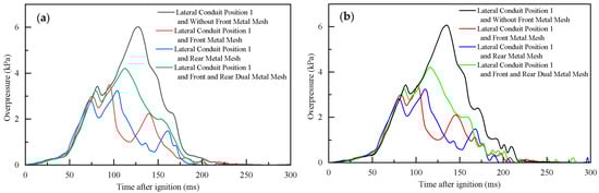
Figure 7.
The overpressure–time diagram under operating conditions in metal mesh within the pipeline in coordination with the side venting duct in position 1: (a) front overpressure; (b) back overpressure.
The overpressure profiles of the conditions with a front metal mesh and both front and rear metal meshes exhibit certain similarities. After the precursor wave breaks through the blowout film, the overpressure briefly decreases and then reappears with two increases, and the pressure also decays earlier. In conjunction with the flame images, it can be observed that flame quenching is more likely to occur at this time. The first increase is due to the wave system redeveloping after a brief venting at the beginning of the explosion, which impacts the front metal wire mesh earlier, and the resulting disturbance hinders the interaction, increasing the flow field gradient in the unburned gas region. Meanwhile, the lateral blowout guide pipe serves as a blowout outlet connecting the explosion flame reaction zone and the metal wire mesh region with the external environment, approaching atmospheric pressure. The pressure difference between the inside and outside causes fluid to flow in the opposite direction of flame propagation, and the flame tends to propagate toward the low-pressure area. Some premixed gas in the unburned area is also driven out through the lateral blowout guide pipe by the overpressure, causing the blowout guide pipe to play a positive feedback venting role between the unburned gas area and the flame reaction zone, leading to a brief increase in overpressure followed by continuous venting. The second increase is due to the flame propagating to the middle and rear sections of the pipeline, away from the No. 1 blowout guide pipe position, weakening the guide pipe venting effect. On the other hand, the unquenched laminar flame penetrates the metal wire mesh, and the changes in the front edge structure and propagation speed of the flame after passing through the mesh compensate for the overpressure decay to some extent, causing the overpressure to re-aggregate and rise, and finally decrease under the end blowout action. Pressure fluctuations at the tail end of the pressure curves for each condition can be observed in the figure, which are caused by the overpressure energy being consumed by the metal mesh and the wall, and the end blowout vent communicating with the external environment after the film breaks, interfering with the internal flow and resulting in unstable gas flow and heat exchange, leading to the disorder of the explosion wave system.
4. Conclusions
This study simulates a natural gas pipeline explosion on a self-built square pipeline experimental platform. By installing lateral blowout guide pipes at different positions and conducting experiments with different metal wire mesh positions in the pipeline in conjunction with the lateral guide pipes, the flame propagation characteristics of methane/air–premixed gas in the pipeline are analyzed. The main conclusions are as follows:
- Lateral ducts can effectively dissipate a portion of the energy generated during a methane explosion, thereby prolonging the flame propagation time within the pipe and reducing the peak explosion overpressure.
- As the position of the lateral vent pipe approaches the ignition end, the venting action gradually enhances, and the deflagration effect is significantly superior to that of the vent pipes in the middle and rear positions.
- The metal mesh within the pipe will impact the structure and speed of the flame front after it permeates through the mesh. Under such circumstances, the front-end lateral guide pipe can effectively mitigate the enhanced turbulence intensity and propagation speed induced by the flame’s penetration through the metal mesh.
- The frontal lateral deflagration vent pipe releases the not fully developed premixed flame in advance, reducing the intensity of the explosion, while the rear-end metal mesh fully exerts its quenching performance, extinguishing the flame.
Author Contributions
Conceptualization, Y.H. and Z.L.; methodology, Y.H.; software, Z.L. and Y.T.; validation, Y.H. and Z.L.; formal analysis, Y.H.; investigation, Y.H. and Z.L.; resources, Y.H.; data curation, Y.H. and Z.L.; writing—original draft preparation, Y.H. and Z.L.; writing—review and editing, Y.H., Z.L., Y.T. and W.D.; visualization, Y.H.; supervision, Y.H.; project administration, Y.H.; funding acquisition, Y.H. All authors have read and agreed to the published version of the manuscript.
Funding
This research was funded by The 2021 Jiangsu Province Key Research and Development Plan (Social Development) Project, grant number BE2021641.
Data Availability Statement
The data that support the findings of this study are available from the corresponding author upon reasonable request.
Conflicts of Interest
The authors declare no conflict of interest.
References
- Chen, C.H.; Sheen, Y.N.; Wang, H.Y. Case analysis of catastrophic underground pipeline gas explosion in Taiwan. Eng. Fail. Anal. 2016, 65, 39–47. [Google Scholar] [CrossRef]
- Gao, Y.; Fu, G.; Nieto, A. A comparative study of gas explosion occurrences and causes in China and the United States. Int. J. Min. Reclam. Environ. 2016, 30, 269–278. [Google Scholar] [CrossRef]
- Yin, W.; Fu, G.; Yang, C.; Jiang, Z.; Zhu, K.; Gao, Y. Fatal gas explosion accidents on Chinese coal mines and the characteristics of unsafe behaviors: 2000–2014. Saf. Sci. 2017, 92, 173–179. [Google Scholar] [CrossRef]
- Cao, X.; Ren, J.; Zhou, Y.; Wang, Q.; Gao, X.; Bi, M. Suppression of methane/air explosion by ultrafine water mist containing sodium chloride additive. J. Hazard. Mater. 2015, 285, 311–318. [Google Scholar] [CrossRef] [PubMed]
- Ferrara, G.; Di Benedetto, A.; Salzano, E.; Russo, G. CFD analysis of gas explosions vented through relief pipes. J. Hazard. Mater. 2006, 137, 654–665. [Google Scholar] [CrossRef] [PubMed]
- Ferrara, G.; Willacy, S.K.; Phylaktou, H.N.; Andrews, G.E.; Di Benedetto, A.; Salzano, E.; Russo, G. Venting of gas explosion through relief ducts: Interaction between internal and external explosions. J. Hazard. Mater. 2008, 155, 358–368. [Google Scholar] [CrossRef] [PubMed]
- Nie, B.; He, X.; Zhang, R.; Chen, W.; Zhang, J. The roles of foam ceramics in suppression of gas explosion overpressure and quenching of flame propagation. J. Hazard. Mater. 2011, 192, 741–747. [Google Scholar] [CrossRef] [PubMed]
- Qi, S.; Du, Y.; Wang, S.; Zhou, Y.; Li, G. The effect of vent size and concentration in vented gasoline-air explosions. J. Loss Prev. Process. Ind. 2016, 44, 88–94. [Google Scholar] [CrossRef]
- Sezer, H.; Kronz, F.; Akkerman, V.y.; Rangwala, A.S. Methane-induced explosions in vented enclosures. J. Loss Prev. Process. Ind. 2017, 48, 199–206. [Google Scholar] [CrossRef]
- Ugarte, O.J.; Akkerman, V.y.; Rangwala, A.S. A computational platform for gas explosion venting. Process. Saf. Environ. Prot. 2016, 99, 167–174. [Google Scholar] [CrossRef]
- Wang, B.; Rao, Z.; Xie, Q.; Wolański, P.; Rarata, G. Brief review on passive and active methods for explosion and detonation suppression in tubes and galleries. J. Loss Prev. Process. Ind. 2017, 49, 280–290. [Google Scholar] [CrossRef]
- Wen, X.; Xie, M.; Yu, M.; Li, G.; Ji, W. Porous media quenching behaviors of gas deflagration in the presence of obstacles. Exp. Therm. Fluid Sci. 2013, 50, 37–44. [Google Scholar] [CrossRef]
- Yu, M.; Wan, S.; Xu, Y.; Zheng, K.; Liang, D. The influence of the charge-to-mass ratio of the charged water mist on a methane explosion. J. Loss Prev. Process. Ind. 2016, 41, 68–76. [Google Scholar] [CrossRef]
- Yu, M.; Wan, S.; Xu, Y.; Zheng, K.; Liang, D. Suppressing methane explosion overpressure using a charged water mist containing a NaCl additive. J. Nat. Gas Sci. Eng. 2016, 29, 21–29. [Google Scholar] [CrossRef]
- Rocourt, X.; Awamat, S.; Sochet, I.; Jallais, S. Vented hydrogen–air deflagration in a small enclosed volume. Int. J. Hydrogen Energy 2014, 39, 20462–20466. [Google Scholar] [CrossRef]
- Xing, H.; Xu, Q.; Song, X.; Wang, Y.; Li, B.; Xie, L. The effects of vent area and ignition position on pressure oscillations in a large L/D ratio duct. Process. Saf. Environ. Prot. 2020, 135, 166–170. [Google Scholar] [CrossRef]
- Zhao, Y.; Wu, J.; Zhou, R.; Cai, J.; Bai, Y.; Pang, L. Effects of the length and pressure relief conditions on propagation characteristics of natural gas explosion in utility tunnels. J. Loss Prev. Process. Ind. 2022, 75, 104679. [Google Scholar] [CrossRef]
- Ajrash, M.J.; Zanganeh, J.; Moghtaderi, B. Deflagration of premixed methane–air in a large scale detonation tube. Process. Saf. Environ. Prot. 2017, 109, 374–386. [Google Scholar] [CrossRef]
- Ajrash, M.J.; Zanganeh, J.; Moghtaderi, B. Flame deflagration in side-on vented detonation tubes: A large scale study. J. Hazard. Mater. 2018, 345, 38–47. [Google Scholar] [CrossRef]
- Wan, S.; Yu, M.; Zheng, K.; Wang, C.; Yuan, Z.; Yang, X. Effect of side vent size on a methane/air explosion in an end-vented duct containing an obstacle. Exp. Therm. Fluid Sci. 2019, 101, 141–150. [Google Scholar] [CrossRef]
- Wan, S.; Yu, M.; Zheng, K.; Xu, Y.; Wang, C.; Yuan, Z. Influence of side venting position on methane/air explosion characteristics in an end-vented duct containing an obstacle. Exp. Therm. Fluid Sci. 2018, 92, 202–210. [Google Scholar] [CrossRef]
- Wan, S.; Yu, M.; Zheng, K.; Xu, Y.; Yuan, Z.; Wang, C. Influence of obstacle blockage on methane/air explosion characteristics affected by side venting in a duct. J. Loss Prev. Process. Ind. 2018, 54, 281–288. [Google Scholar] [CrossRef]
- Yu, M.; Wan, S.; Zheng, K.; Guo, P.; Chu, T.; Wang, C. Effect of side venting areas on the methane/air explosion characteristics in a pipeline. J. Loss Prev. Process. Ind. 2018, 54, 123–130. [Google Scholar] [CrossRef]
- Duan, Y.; Long, F.; Long, J.; Yu, S.; Jia, H. Exploration of the critical hydrogen-mixing ratio of quenching methane/hydrogen mixture deflagration under the effect of porous materials in barrier tube. Int. J. Hydrogen Energy 2023, 48, 22288–22301. [Google Scholar] [CrossRef]
- Duan, Y.; Wang, S.; Yang, Y.; Li, Y.; Zheng, K. Experimental study on methane explosion characteristics with different types of porous media. J. Loss Prev. Process. Ind. 2021, 69, 104370. [Google Scholar] [CrossRef]
- Long, F.; Duan, Y.; Yu, S.; Jia, H.; Bu, Y.; Huang, J. Effect of porous materials on explosion characteristics of low ratio hydrogen/methane mixture in barrier tube. J. Loss Prev. Process. Ind. 2022, 80, 104875. [Google Scholar] [CrossRef]
- Lv, P.; Li, T.; Zhang, Y.; Pang, L.; Yang, K. Influence of the opening pressure of explosion-venting surface on methane deflagration characteristics in municipal sewage confined spaces. Process. Saf. Prog. 2023, 42, 729–736. [Google Scholar] [CrossRef]
- Jin, K.; Duan, Q.; Chen, J.; Liew, K.M.; Gong, L.; Sun, J. Experimental study on the influence of multi-layer wire mesh on dynamics of premixed hydrogen-air flame propagation in a closed duct. Int. J. Hydrogen Energy 2017, 42, 14809–14820. [Google Scholar] [CrossRef]
- Jin, K.; Wang, Q.; Duan, Q.; Chen, J.; Sun, J. Effect of ignition position on premixed hydrogen-air flame quenching behaviors under the action of metal wire mesh. Fuel 2021, 289, 119750. [Google Scholar] [CrossRef]
- Jin, K.; Wang, Q.; Duan, Q.; Chen, J.; Sun, J. Effect of metal wire mesh on premixed H2/air flame quenching behaviors in a closed tube. Process. Saf. Environ. Prot. 2021, 146, 770–778. [Google Scholar] [CrossRef]
- Jin, K.; Wang, Q.; Duan, Q.; Sun, J. Effect of single-layer wire mesh on premixed methane/air flame dynamics in a closed pipe. Int. J. Hydrogen Energy 2020, 45, 32664–32675. [Google Scholar] [CrossRef]
- Cao, X.; Wang, Z.; Wang, Y.; Wang, Z.; Zhou, Y. Effect of wire mesh structure parameter on the flame propagation characteristics of syngas explosion. Fuel 2023, 334, 126658. [Google Scholar] [CrossRef]
- Cao, X.; Wang, Z.; Wang, Z.; Lu, Y.; Sun, S.; Xu, J. Experimental research on the flame resistance characteristics of wire mesh for syngas explosion. Process. Saf. Environ. Prot. 2023, 175, 34–47. [Google Scholar] [CrossRef]
- Feng, X.; Zhang, H.; Si, F.; Dou, J.; Li, M.; Wu, L.; Wang, S.; Zhao, L. Suppression characteristics of multi-layer metal wire mesh on premixed methane-air flame propagation. Front. Mater. 2023, 10, 1107133. [Google Scholar] [CrossRef]
- Wu, J.; Zhao, Y.; Zhou, R.; Cai, J.; Bai, Y.; Pang, L. Suppression effect of porous media on natural gas explosion in utility tunnels. Fire Saf. J. 2022, 128, 103522. [Google Scholar] [CrossRef]
- Zhang, S.; Wang, Z.; Zuo, Q.; Jiang, J.; Cheng, C. Suppression effect of explosion in linked spherical vessels and pipelines impacted by wire-mesh structure. Process. Saf. Prog. 2015, 35, 68–75. [Google Scholar] [CrossRef]
- Cui, Y.Y.; Wang, Z.R.; Zhou, K.B.; Ma, L.S.; Liu, M.H.; Jiang, J.C. Effect of wire mesh on double-suppression of CH4/air mixture explosions in a spherical vessel connected to pipelines. J. Loss Prev. Process. Ind. 2017, 45, 69–77. [Google Scholar] [CrossRef]
- Wang, Z.; Lu, Y.; Cao, X.; Yu, Y.; Jiang, J.; Jiao, F.; Ma, S. Wire-mesh inhibition of jet fire induced by explosion venting. J. Loss Prev. Process. Ind. 2021, 70, 104408. [Google Scholar] [CrossRef]
- Lu, Y.; Wang, Z.; Cao, X.; Cui, Y.; Sun, P.; Qian, C. Interaction mechanism of wire mesh inhibition and ducted venting on methane explosion. Fuel 2021, 304, 121343. [Google Scholar] [CrossRef]
- Wang, Z.; Zhang, Z.; Tian, W.; Wang, Z. Coupling effect of side explosion vent and wire mesh on suppressing methane explosion in a closed duct. J. Loss Prev. Process. Ind. 2022, 76, 104738. [Google Scholar] [CrossRef]
Disclaimer/Publisher’s Note: The statements, opinions and data contained in all publications are solely those of the individual author(s) and contributor(s) and not of MDPI and/or the editor(s). MDPI and/or the editor(s) disclaim responsibility for any injury to people or property resulting from any ideas, methods, instructions or products referred to in the content. |
© 2023 by the authors. Licensee MDPI, Basel, Switzerland. This article is an open access article distributed under the terms and conditions of the Creative Commons Attribution (CC BY) license (https://creativecommons.org/licenses/by/4.0/).