Abstract
Based on the winding function considering the slot width and the air-gap permeability considering the slot opening width, the main radial electromagnetic force wave expressions of the induction motor are determined. The electromagnetic force-vibration prediction model of the induction motor is established. The natural frequency and acoustic radiation model of a finite-length cylindrical shell with two ends clamped is deduced. On this basis, an improved magnetic noise prediction model of cage induction motor is improved, which can calculate the combined effects of electromagnetic force on the axis and circumferential modes of the stator system. Aiming at two different noise reduction targets, an optimization method is proposed to reduce the overall electromagnetic noise of the motor without sacrificing efficiency and output torque. The feasibility of the model for electromagnetic noise prediction is verified by finite element simulation and experiments. For a 30/26 slots five-phase induction motor, low-noise analysis and optimization schemes of the opening width for two different targets are given. The results show that the larger slot opening scheme can also result in less magnetic noise for the right selection, which is contrary to the common design rule that recommends minimizing slot opening to reduce magnetic noise.
1. Introduction
In the environment of prominent energy problems, new energy vehicles ushered in unprecedented broad prospects. In addition to power density and fault-tolerant performance, the +electromagnetic vibration and noise of electric vehicles, which are closely related to NVH characteristics, are also attracting more and more attention. The same as three-phase motors, the active noise reduction technology [,,,] of harmonic current injection into multiphase motors can only eliminate the electromagnetic force space harmonics of order 0 and 2p. However, the stator elliptic mode is usually the mode with the most vibration noise radiation, so this technology cannot be applied to four-pole or six-pole motors. Other active noise suppression techniques often require more complex closed-loop control and electromechanical equipment [], so it is necessary to find some low-noise rules that can be applied at the motor design stage. Rotor closing groove, increasing air gap length and rotor chute are commonly used in low noise design methods, but the side effect is to significantly reduce the performance of the motor.
Literature [] mainly aimed at the tooth harmonic content of the three-phase induction motor electromagnetic wave [,], i.e., the interaction of air-gap permeance harmonics and fundamental magnetomotive force (MMF). The slot opening width of the optimization design principles are given, but due to the different phase number, the air-gap flux density characteristics and the electromagnetic harmonic content of the five-phase squirrel cage induction motor (FSCIM) are also different from that of the three-phase motor. Therefore, the electromagnetic vibration characteristics of the five-phase motor needs to be studied separately.
Aimed at reducing the magnetic noise of the FSCIM, an improved optimization method of low electromagnetic noise is proposed, which does not weaken the electromagnetic torque at the cost of changing the stator and rotor slot openings. Firstly, the five-phase winding function is derived from the superposition of a single conductor or a single coil, which includes the slot width. Then, combined with the stator and rotor current calculated by the single-phase harmonic expansion circuit [,,] and the air-gap permeance function considering the slot openings, the radial air-gap flux density distribution is obtained. Furthermore, an improved analytical model of electromagnetic force, vibration and noise radiation was established to further consider the joint effect of electromagnetic force on the axial and radial modes of the stator system, and the feasibility of the model was verified by finite element simulation and noise measurement experiments. Next, on the basis of [], the qualitative analysis of the rotor slot width and noise suppression basis was conducted. Finally, the slot opening width was optimized for the two kinds of integrated noise optimization objectives. Taking the five-phase cage induction motor with stator and rotor 30/26 slots as an example, the recommended schemes of low-noise slot opening design are given.
2. Analytical Model of Electromagnetic Vibration
2.1. Electromagnetic Force Basis
The electromagnetic force of the motor mainly includes magnetostriction and Maxwell force. Magnetostriction generally does not cause high-frequency magnetic noise [,], so that the impact on noise radiation is negligible. Maxwell force is composed of radial and tangential components, but since the radial component is usually an order of magnitude larger than the tangential component, and the tangential component mainly causes resonance in asymmetric windings and single-phase motors. In a five-phase induction motor with normal windings, electromagnetic noise due to radial components of Maxwell stress can be considered only [,]. The distribution of the exciting force in the air gap is mainly expressed in the form of electromagnetic force waves per unit area [,,].
where Br is the radial component of the air-gap flux density; μ0 is the air permeability; θs is the mechanical angular position on the circumference. The two-dimensional Fourier decomposition of the electromagnetic force density can be expressed as a superposition of a series of harmonics of the frequencies fn and the m-th order in space, where m also represents the number of pole pairs of the harmonic:
where Pnm is the electromagnetic force wave amplitude.
If the rotor skew and end effect are ignored, the Maxwell stress will only cause the modal resonance in the circumferential direction of the stator system (composed of the stator yoke, stator teeth and stator windings). At this time, the stator system can be equivalently regarded as a ring for modal analysis. When the frequency of the m-th space harmonic of the electromagnetic force is equal to or similar to the natural frequency of the m-th order circumferential mode of the stator system, the vibration will resonate and the electromagnetic noise radiation will have a maximum value. Especially in the operating speed range of the induction motor, this situation should be avoided. As is known, the electromagnetic force amplitude is inversely proportional to the fourth power of the force wave order [,], so for small and medium-sized motors, only force waves with m less than 4 need to be considered.
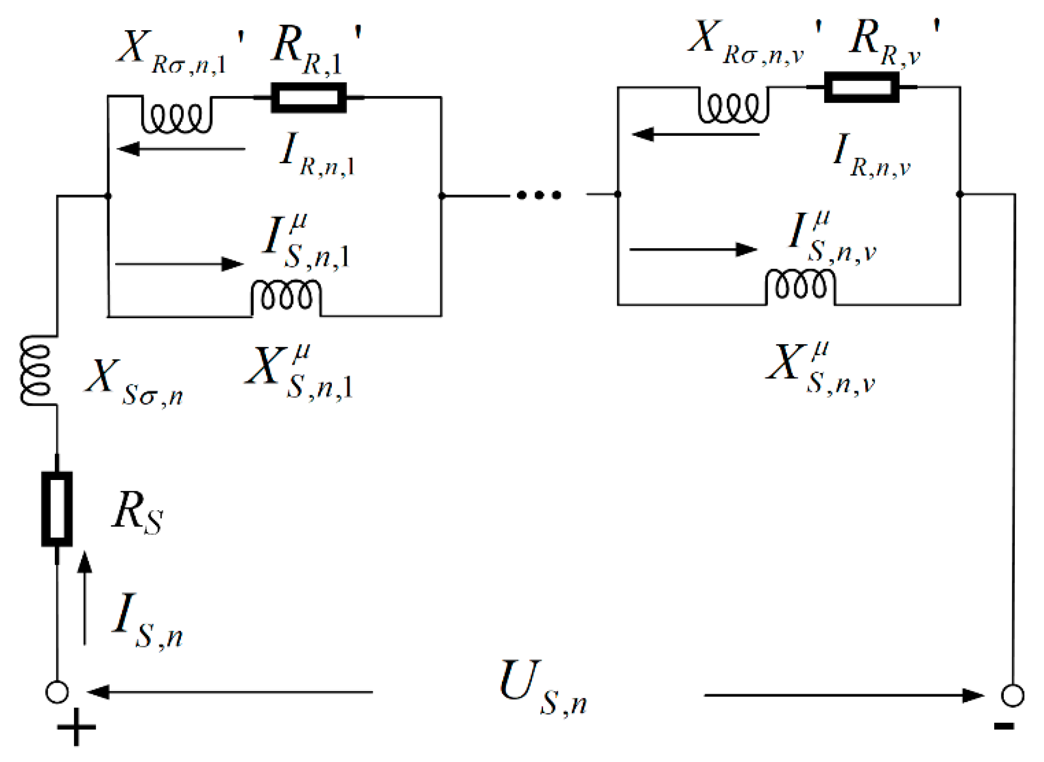
2.2. Current Computation
The stator and rotor phase currents, including all spatial and time harmonics, can be calculated using the single-phase harmonic expansion circuit []. As shown in Figure 1, each voltage harmonic US,n with frequency fn generated by the five-phase PWM inverter circuit corresponds to an equivalent circuit containing the influence of v stator winding space harmonics.
Figure 1.
Harmonics expansion circuit.
According to Figure 1, the n main loop equations can be obtained as:
the node equations are:
the small loop equations are:
where and are stator and rotor resistance, is the leakage reactance of stator to n-th time harmonic, is the harmonic magnetizing reactance of the stator with respect to the n-th time harmonic and v-th space harmonic [,] and is the leakage reactance of the rotor with respect to n-th time harmonic and v-th space harmonic. The detailed expressions of the above circuit parameters can be calculated from [].
where is v-th space harmonic leakage inductance, p is pole pair and Kwv is v-th winding factor.
For a certain time harmonic, the 2v + 1 Equations (3)–(5) can be combined to obtain the following matrix:
where I is an identity matrix, 0 is a zero matrix, is the column vector and and are and diagonal matrixes, respectively. The time and space harmonic currents of the stator and rotor can be obtained by substituting the parameters of each motor into the matrix (9).
2.3. Analytical Calculation of Electromagnetic Force
Air-gap flux density is the basis of motor energy exchange, and the radial component of flux density Br can be expressed as [,,,]:
where and are stator and rotor MMF, Λ is the air-gap permeability taking the slotted effects into account.
The specific expressions of each part of air-gap permeability have been given in detail in [] and []. The influence of stator and rotor slots is proportional to the width of the slot opening. and are inversely proportional to the number of magnetic conductivity harmonics k1 and k2. Based on the known distribution of windings, the winding function of single conductor or single coil WFs(θs) [,] can be used to obtain the expression of stator winding function of each phase by using the superposition principle, as shown in Figure 2. Then the stator/rotor MMF can be obtained by multiplying the winding function (12) by the current obtained from Section 2.2.
where ksv and kyv are the slotting coefficient and short distance coefficient of v pair poles harmonics, respectively.
Figure 2.
Winding function relation between coil and conductor at different pitch. (a) Whole pitch winding; (b) short pitch winding.
By substituting (9)−(11) into (1), the Maxwell force wave generated by all magnetic density harmonics can be determined, if only the force wave that plays a major role in noise is considered, that is, the low order force wave Pbelt generated by the interaction between harmonics of phase belt of stator and rotor MMF and tooth harmonics of air-gap permeability. The characteristics of force waves are given in Table 1.
Table 1.
Characteristics of phase belt force wave Pbelt.
By analyzing the expression of air-gap permeability, it can be seen that, regardless of the value of l, the amplitude of the phase belt force wave of slot effect and the width of slot opening always satisfy [,]:
where PS and PR are the amplitude of harmonics of stator and rotor air gap permeability, β1 and β2 are the slot opening ratio. The slot parameters are shown in Figure 3.
Figure 3.
Schematic diagram of stator and rotor slots.
The slot size of the rotor and the rotor directly influence the amplitude of wave, while the number of pole slots influences the order of wave. The frequency of force wave is mainly influenced by the number of rotor slots Z2, pole pair p, slip rate s and power supply frequency fn. Generally speaking, in an induction motor from starting to stable operation, the slip ranges from 1 to less than 0.05. As the five-phase PWM power supply contains many rich time harmonics, the frequency range of the Maxwell force wave is too wide to cover the natural frequency of the stator system.
2.4. Natural Frequency of Stator System
The stator system is mainly composed of an iron core and windings—tooth and housing—which can be regarded as equivalent rings, respectively. The natural frequencies of the core and windings (tooth) can be obtained by solving the second-order characteristic equation of the cylindrical shell motion according to the Donnel–Mushtari theory [,].
It is worth noting that the vibration characteristics of the housing can be equivalent to a closed cylindrical shell with both ends constrained []. As to common motors, both ends are clamped (C). For the magnetic bearing motor, boundary conditions can be regarded as a simply supported (SS). The axial vibration mode a will be introduced in both cases, and the natural frequency of each (a, m) mode should be calculated.
The frequency and stiffness of the frame with end bells can be obtained, such as with the iron core; however is redefined as the solution of the third-order characteristic motion equation of the cylindrical shell []. According to the Donnel–Mushtari theory, the characteristic motion equation is:
with the constants as shown below:
for both boundary constraints:
Only the smallest real root from (15) is related to the natural frequency of vibration, and the stiffness and natural frequency of the frame (a, m) mode are:
For small and medium induction motors, the manufacturing tolerance between the outer diameter of the stator core and the inner diameter of the frame is ±0.02 to ±0.1 mm, with the ends connected by an interference fit. There is no relative displacement between the core, winding, teeth and housing, which can be regarded as a whole. At this time, the stiffness and mass of the stator system can be approximately regarded as the algebraic sum of the mass and stiffness of each part [], so the stator system (a, m) mode natural frequency can be expressed as:
The subscripts 1, 2, and 3 represent the iron core, windings and tooth and housing, respectively.
2.5. Vibration Characteristics
The radial electromagnetic force wave of the motor acts on the inner surface of the stator core. When the m-order force wave with frequency fP is close to the natural frequency of the stator system (a, m) mode, the resonance condition is satisfied, and the surface of the motor casing will generate a severe vibration, and its dynamic displacement amplitude can be expressed as:
where An,a,m is the dynamic amplification factor, ξa,m is the damping coefficient, l1 is the length of the stator core and Mdz is the mass of the stator system.
2.6. Model Validation
Taking a five-phase motor as the prototype, the analytical model is verified by the finite element method. The basic parameters of the motor are shown in Table 2, and the slot shape is shown in Figure 3.
Table 2.
Prototype parameters.
The main low-order modal natural frequencies of the motor stator system are calculated using the analytical model and Ansys finite element software, respectively. As shown in Table 3 (the finite element results in parentheses), the root mean square error (RMSE) is 330.1 Hz, and the mean absolute percentage error (MAPE) was 4.38%. The results show that the analytical model in this paper can calculate the modal characteristics well and provide the basis for noise analysis. In order to consider the main low-order force wave characteristics, according to the force wave characteristics of Table 1, the main low-order force waves in the range from 2 to 10 for k1 and k2 are given in Table 4.
Table 3.
Results of the natural frequency of stator system.
Table 4.
Prototype parameters.
3. Magnetic Noise Radiation Calculation
3.1. Noise Radiation Model
For the reason that the motor noise is generally measured in the near field, the acoustic radiator cannot be treated as an infinite cylindrical model. Therefore, the sound power resulted from (fn, m) order force wave acting on (a, m) mode can be expressed as:
where Sc is the surface area of the housing and σI is the relative acoustic emissivity depending on the mode (a, m) and the ratio of the length to the width of the housing.
For an infinitely long cylindrical shell, σI can be simplified as []:
where is the second kind of Hankel equation of m-th order and k0 is the acoustic wave number.
For different boundary conditions at both ends, the relative acoustic emissivity can be obtained by substituting the axial wave number kz0 into the sound-wave radiation equation:
where z is the axial coordinate; kr and kz are the radial and axial components of the acoustic wavenumber; and [].
Then the numerical solution of the analytical model can be obtained via Matlab, so as to further predict the sound power level of magnetic noise:
where W0 = 10−12 W is the reference sound power and △LA(n) is a frequency (fn)-dependent A-weighting factor [,,].
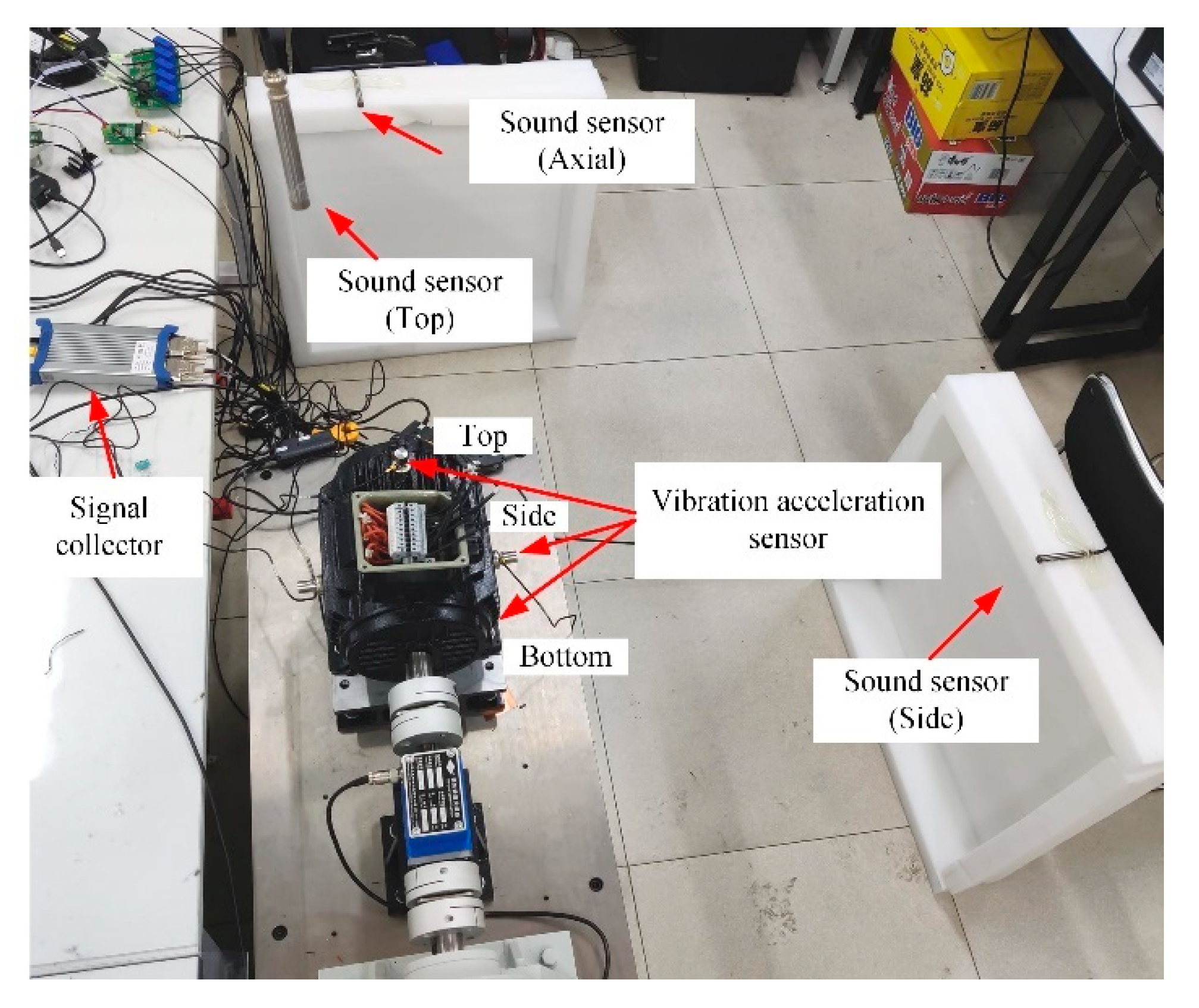
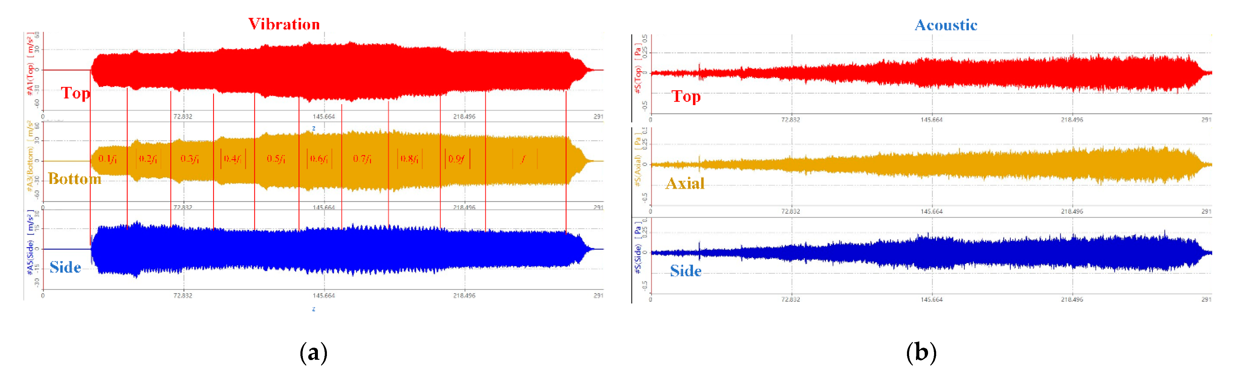
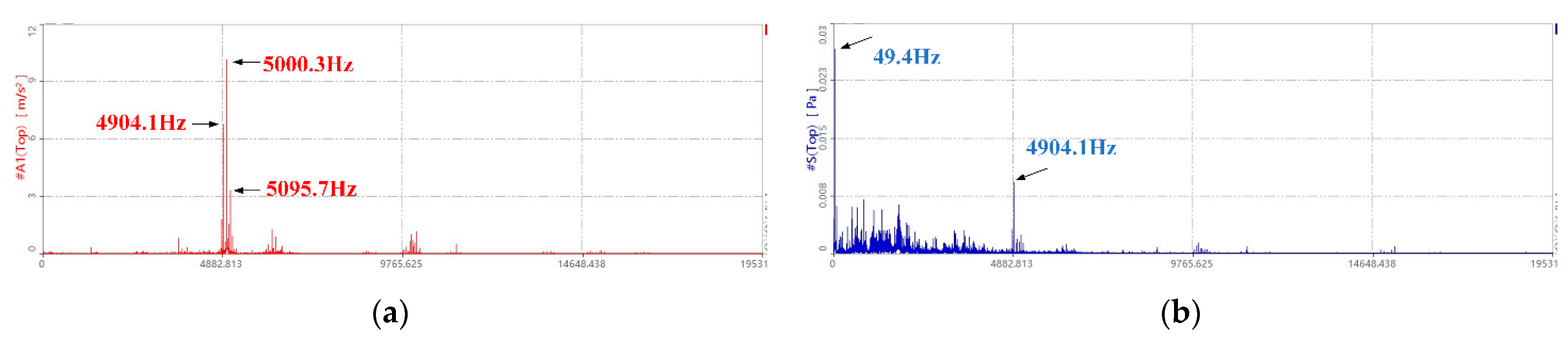
3.2. Noise Prediction Verification Experiment
For the motors shown in Table 2, the five-phase SPWM control circuit is used to supply power to the motors to conduct actual noise measurement experiments. There are three vibration acceleration sensors at the top, side and bottom on the surface of the casing, and three sound pressure sensors are set at the top, axial and side 1.5 times the axial length of the motor. The overall layout of the specific test platform is shown in the Figure 4 is shown.
Figure 4.
Five-phase motor vibration and noise measurement platform.
In terms of Figure 5, it can be found that the change trend of the vibration acceleration at the top and bottom of the casing is consistent, while the change trend at the side is just the opposite, which reveals that the electromagnetic force mainly excites the resonance of the 2-nd mode of the stator system. The Fourier spectrum analysis of the vibration acceleration and noise results under steady state conditions are given in Figure 6. It is found that the vibration frequency is mainly concentrated around 5000 Hz, which just corresponds to (m = 2, a = 3) the natural frequency of the modal. It is obviously consistent with the judgment of the macroscopic result in Figure 6. In addition, the high frequency belt in the noise spectrum is consistent with the vibration spectrum, but many components that do not exist in the vibration spectrum appear in the low frequency band, which is probably caused by the mechanical noise of the rotating shaft and the power switching.
Figure 5.
Vibration and noise transient measurement results. (a) Vibration acceleration in three directions at the top, bottom and sides of the enclosure; (b) Sound pressure in three directions: top, axial and side.
Figure 6.
Comparison of vibration and noise spectrum in steady state. (a) Vibration acceleration spectrum; (b) sound pressure spectrum.
4. Low Noise Slot Opening Design
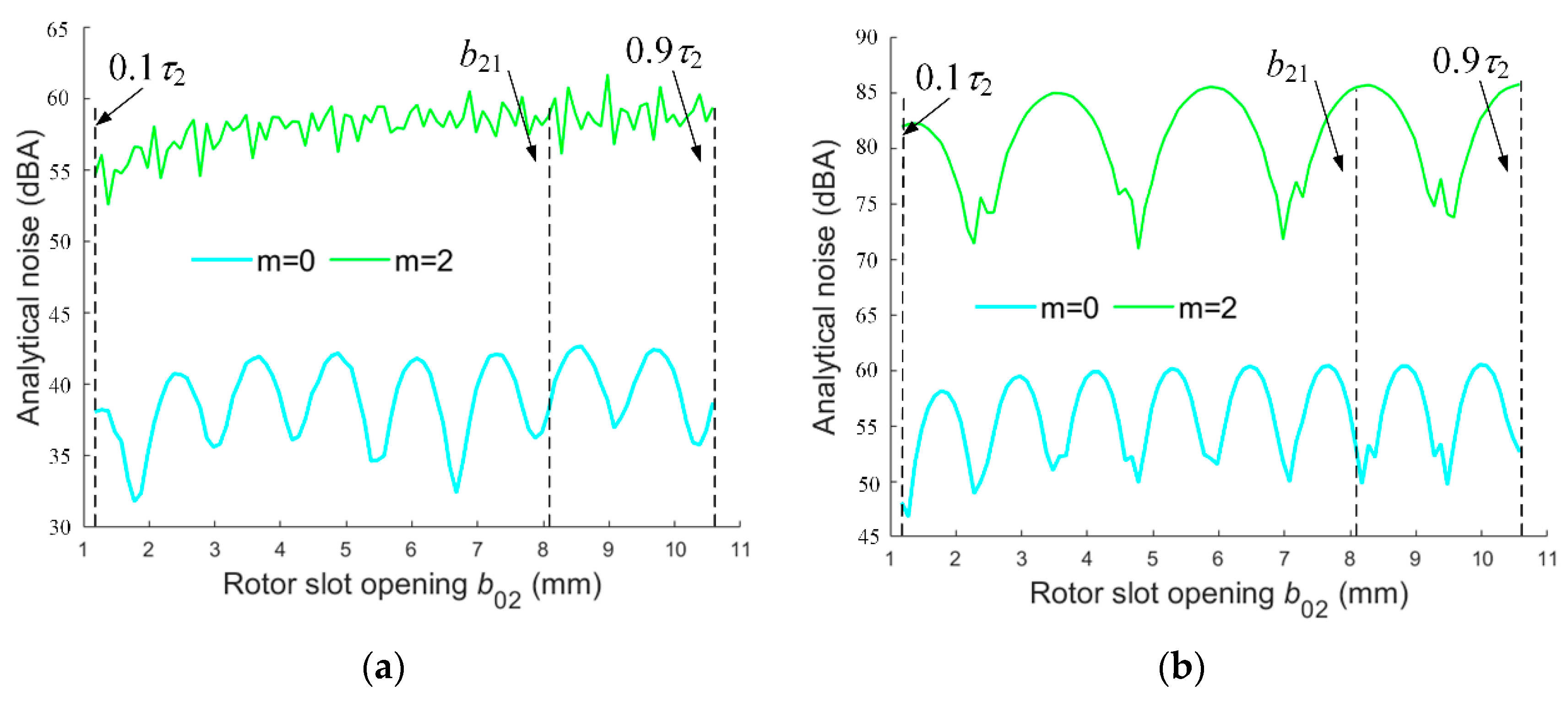
4.1. Low Noise Fundamental Analysis
According to Table 1, there are two main methods to reduce electromagnetic vibration noise in the design stage. One is to choose the pole-slot combination to avoid resonance between the electromagnetic force of (fp, m) and motor structure of (fa,m, m); the second is to reduce the amplitude of the electromagnetic force wave by correctly selecting the slotting strategy of the stator and the rotor, thereby reducing the electromagnetic vibration noise. In this paper, based on the given pole-slot match, the electromagnetic vibration noise can be reduced by changing the width of the slot opening without the reduction of output performance.
According to (13), when k1β1 or k2β2 is an integer, the electromagnetic force of m = k2Z2 − 2m1pk1 + lp will decrease to 0. Therefore, the amplitude of electromagnetic force of a certain order can be further expressed as []:
where Z01 and Z02 are integers and the superscript * represents the slot width value of exactly weakening force wave.
If k1 or k2 is equal to 1, then the width of the rotor slot opening cannot weaken any force wave. Therefore, to weaken the electromagnetic force amplitude through the width of the slot opening, k1 and k2 should be integers greater than 2. Substituting the value range of Z01 and Z02 into (33) and (34), the slot width optimization range for the electromagnetic force of order m = k2Z2 − 2m1pk1 + lp can be obtained:
The optimal design of motor is a nonlinear, multi-physical field coupling and anisotropic problem, so focusing on the weakening of one order of force wave is likely to lead to the increase of the amplitude of other order of force wave. In addition, the five-phase motor is mainly controlled by PWM frequency conversion. In the process from start-up to stable operation, the power supply voltage contains abundant time harmonics, so the radial electromagnetic force wave and the stator mode are likely to resonance. To sum up, the optimal slot opening width is not necessarily the value that makes a certain order of force wave 0 in (33) and (34) but may be a value within the continuous range of (35) and (36). Therefore, two noise optimization objectives are set in this paper:
(1) The minimum total sound power level of each frequency on rated condition:
(2) The sound power amplitude of the maximum noise generated during the start-up is the smallest:
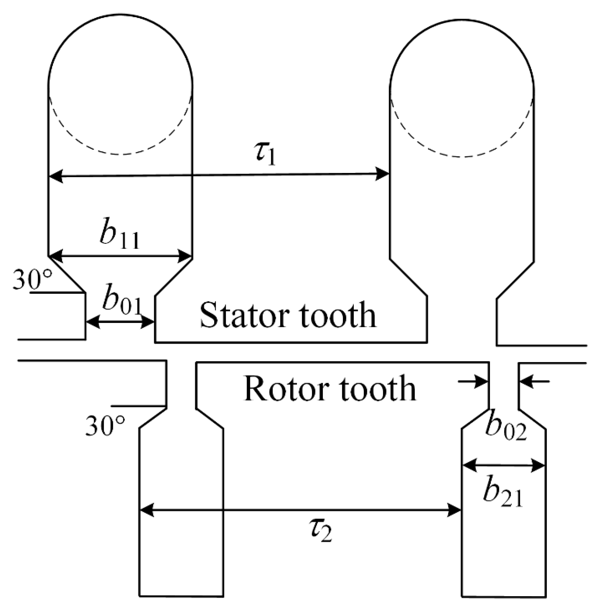
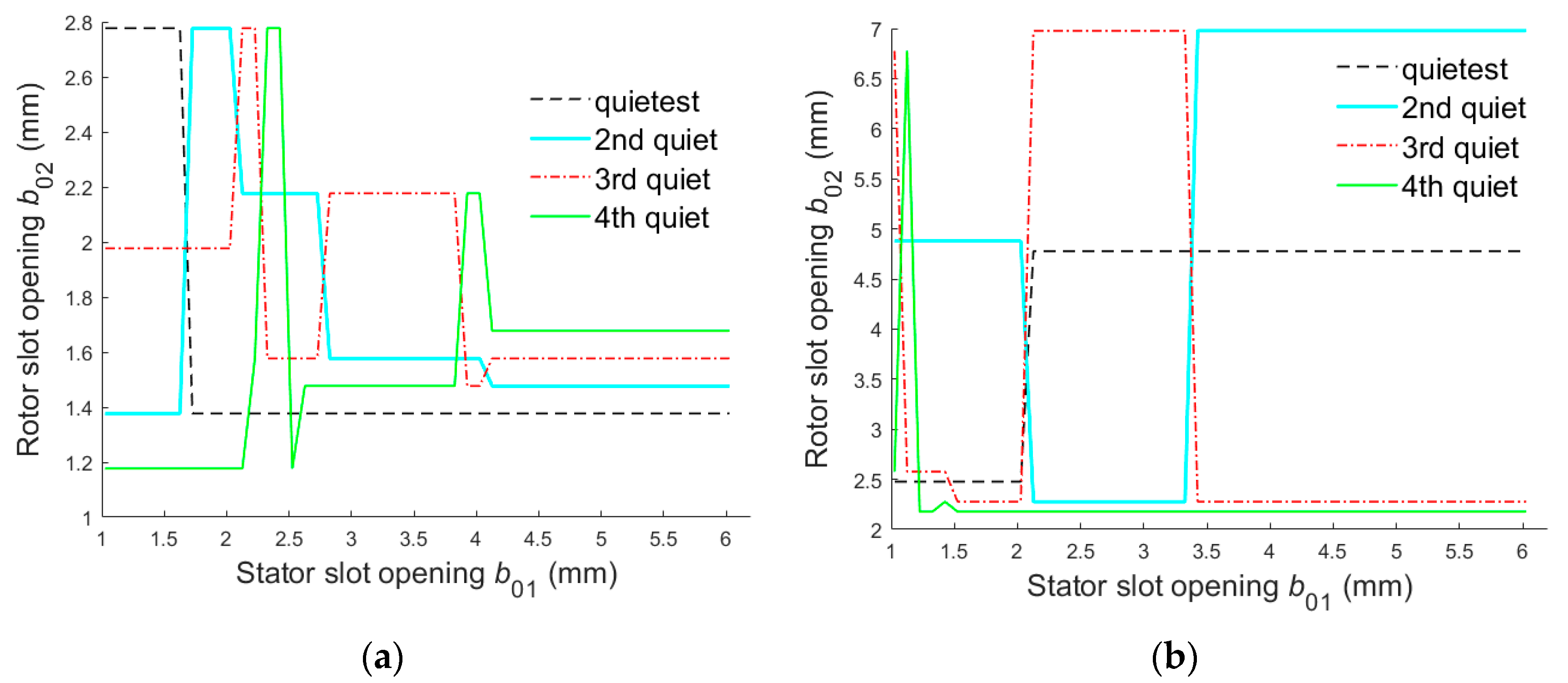
4.2. Slot Opening Width Schemes
For the optimization of the slot opening width, the optimal slot opening scheme with overall electromagnetic noise can be obtained by combining the above two optimization objectives in the range of fixed and rotor slot opening width determined by (35) and (36). In this paper, the test motor shown in Table 2 is taken as the object. In order to consider the influence of as many low-order force waves as possible, the vibration and noise prediction is made for the width of slot opening under all conditions from k1 and k2 from 2 to 10, and the following assumptions are made:
- (1)
- The slip ratio changes linearly, ranging from 1 to 0.05.
- (2)
- In each case, five-phase sequential currents of the same amplitude are passed through the stator windings.
- (3)
Table 5. Value range of stator and rotor slots opening width.- (4)
- Without the consideration of saturation, the air-gap permeability does not contain harmonic content caused by saturation.
For the test motor shown in Table 2, the control variable method was used to calculate the curve of electromagnetic noise by taking the width of the stator and rotor slot opening as independent variables. From Figure 7, we can see that for a certain mode, changing the width of the slot opening can indeed weaken the vibration noise. Furthermore, slot opening width is significantly different for noise suppression sensitivity during start-up and steady-state. That is because, in addition to the amplitude of the electromagnetic force, the vibration noise is also affected by the natural frequency of the stator. In terms of the magnetic noise, the influence of the slot opening width shows a discrete and non-monotonic trend. Actually, it is closer to sinusoidal and there are periodic changes in the sensitivity with a large span, especially in the target (38). It is worth noting that the jitter in the waveform is caused by the same m from different k01, k02, because the curve reflects the total sensitivity of b01 to all k01, k02 combinations, which result in not strictly sine.
Figure 7.
Curve of sound power level with b02 varying from 0.1τ2 to 0.9τ2. (a) Sound power level radiated by b02 associated with main mode for target (37); (b) Sound power level radiated by b02 associated with main mode for target (38).
It can be seen from the above that the amplitude, phase and period of the sensitivity curve of the slot opening width vary significantly with modes. So, it is reasonable to think that the slot width with the smallest overall magnetic noise is not necessarily the smallest. The top four quietest slot opening schemes of targets (37) and (38) for the test motor are given in Figure 8, which are different from conventional knowledge. Considering the engineering practice, b01 and b02 are set smaller than b11 and b21.
Figure 8.
Top four quietest slot opening schemes. (a) For target (37); (b) for target (38).
By analyzing the noise prediction results of all schemes, the quietest scheme of the rotor slot opening is screened for the two different optimization objectives in Section 4.1. As expected, the main quiet slot opening schemes are not the smallest, and b02 shows a non-monotonic and discrete trend with the change of b01. Furthermore, with the increase of b01, the optimal solution of b02 gradually tends to be stable. Due to space limitations, only some quiet slot opening schemes are shown in Table 6.
Table 6.
Main quiet slots opening width schemes (unit: mm).
5. Conclusions
The analytical relationship between the electromagnetic–vibration–noise characteristics of the five-phase cage induction motor and stator/rotor slot opening widths is demonstrated and validated. Based on this, a method for magnetic noise reduction is improved, including the overall harmonics, to optimize the stator/rotor slot opening widths. This method can be applied to the design stage of a low-noise induction machine without the expense of increasing the slot leakage inductance or sacrificing the output performance.
In this paper, the optimization database of slot opening widths is given for a 30/26 slot five-phase induction motor prototype. The results show that the quietest scheme is not always the smallest slot opening, regardless of aims towards noise reduction during start-up or the steady state operation, which is different from common design rules. Because of the periodic sensitivity curve, a wider slot opening can inversely reduce the overall sound power level even more. In terms of the future work, the pole-slot scheme and slot opening width can be considered together to carry out multi-dimensional noise reduction research.
Author Contributions
Writing—original draft preparation, H.C.; validation, Y.X.; investigation, X.L.; supervision, J.Z.; data curation, Q.Z. All authors have read and agreed to the published version of the manuscript.
Funding
This research was funded by the National Natural Science Foundation of China under the grant 51507813.
Institutional Review Board Statement
Not applicable.
Informed Consent Statement
Not applicable.
Data Availability Statement
Not applicable.
Conflicts of Interest
The authors declare no conflict of interest.
References
- Corton, R.; Sawezyn, H.; Belkhayat, D.; Brudny, J. Principe of Magnetic Noise Active Reduction Using Three Phase Systems Due to PWM Inverter Switching. In Proceedings of the 2nd International Seminar on Vibrations and Acoustic Noise of Electric Machinery (VANEM), Łódź, Poland, 1–3 June 2000; Volume 21. [Google Scholar]
- Cassoret, B.; Corton, R.; Roger, D.; Brudny, J.F. Magnetic Noise Reduction of Induction Machines. IEEE Trans. Power Electron. 2003, 18, 570–579. [Google Scholar] [CrossRef]
- Belkhayat, D.; Roger, D.; Brudny, J.F. Active Reduction of Magnetic Noise in Asynchronous Machine Controlled by Stator Current Harmonics. In Proceedings of the 1997 Eighth International Conference on (Conf. Publ. No. 444), Cambridge, UK, 1–3 September 1997. [Google Scholar]
- Liu, H.; Wang, D.; Yi, X.; Zhang, Y. A Unified Fault-tolerant Control for 15-phase Induction Machine Under Various Phase Failure Conditions. Proc. CSEE 2019, 39, 327–336. [Google Scholar]
- Cheng, Z.; Ruan, L.; Huang, S.; Yang, J. Research on Noise Reduction of 3.6 MW Evaporative Cooling Wind Motor Induced by Electromagnetic and Two-Phase Flow Resonance Based on Stator Optimization. Processes 2021, 9, 669. [Google Scholar] [CrossRef]
- Le Besnerais, J.; Lanfranchi, V.; Hecquet, M.; Romary, R.; Brochet, P. Optimal Slot Opening Width for Magnetic Noise Reduction in Induction Motors. IEEE Trans. Energy Convers. 2009, 24, 869–874. [Google Scholar] [CrossRef]
- Chen, Y. Analysis and Control of Motor Noise; Zhejiang University Press: Hangzhou, China, 1987; pp. 5–23. [Google Scholar]
- Shin, K.-H.; Bang, T.-K.; Kim, K.-H.; Hong, K.; Choi, J.-Y. Electromagnetic Analysis and Experimental Study to Optimize Force Characteristics of Permanent Magnet Synchronous Generator for Wave Energy Converter Using Subdomain Method. Processes 2021, 9, 1825. [Google Scholar] [CrossRef]
- Le Besnerais, J.; Lanfranchi, V.; Hecquet, M.; Brochet, P.; Friedrich, G. Acoustic Noise of Electromagnetic Origin in a Fractional-Slot Induction Machine. COMPEL Int. J. Comput. Math. Electr. Electron. Eng. 2008, 27, 1033–1052. [Google Scholar] [CrossRef]
- Brudny, J.F. Modélisation de La Denture Des Machines Asynchrones. Phénomène de Résonance. J. Phys. III 1997, 7, 1009–1023. [Google Scholar] [CrossRef]
- Bossio, G.; De Angelo, C.; Solsona, J.; Garcia, G.; Valla, M.I. A 2-D Model of the Induction Machine: An Extension of the Modified Winding Function Approach. Energy Convers. IEEE Trans. 2004, 19, 144–150. [Google Scholar] [CrossRef]
- Belahcen, A. Vibrations of Rotating Electrical Machines Due to Magnetomechanical Coupling and Magnetostriction. IEEE Trans. Magn. 2006, 42, 971–974. [Google Scholar] [CrossRef]
- Hilgert, T.G.D.; Vandevelde, L.; Melkebeek, J.A.A. Numerical Analysis of the Contribution of Magnetic Forces and Magnetostriction to the Vibrations in Induction Machines. IET Sci. Meas. Technol. 2007, 1, 21–24. [Google Scholar] [CrossRef] [Green Version]
- Devillers, E.; Hecquet, M.; Le Besnerais, J.; Régniez, M. Tangential Effects on Magnetic Vibrations and Acoustic Noise of Induction Machines Using Subdomain Method and Electromagnetic Vibration Synthesis. In Proceedings of the 2017 IEEE International Electric Machines and Drives Conference (IEMDC), Miami, FL, USA, 21–24 May 2017; pp. 1–8. [Google Scholar]
- Gieras, J.F.; Chong, W.; Lai, J.C. Noise of Polyphase Electric Motors; CRC Press: Boca Raton, FL, USA, 2005. [Google Scholar]
- Alger, P.L. Induction Machines: Their Behavior and Uses. J. Clin. Investig. 1993, 91, 2314–2319. [Google Scholar]
- Timár, P.L. Noise and Vibration of Electrical Machines; Elsevier: Amsterdam, The Netherlands, 1989. [Google Scholar]
- Chen, S. Motor Design; Machinery Industry Press: Beijing, China, 2004; pp. 244–247. [Google Scholar]
- Hubert, A. Contribution à l’Étude des Bruits Acoustiques Générés Lors de l’Association Machines Électriques-Convertisseurs Statiques de Puissance. Application à la Machine Asynchrone. Ph.D. Thesis, Université de Technologie de Compiègne, Compiègne, France, 2000. [Google Scholar]
- Gojko, J.M.; Momir, D.D.; Aleksandar, O.B. Skew and Linear Rise of MMF across Slot Modelling-Winding Function Approach. IEEE Trans. Energy Convers. 1999, 14, 315–320. [Google Scholar] [CrossRef]
- Le Besnerais, J.; Lanfranchi, V.; Hecquet, M.; Brochet, P. Optimal Slot Numbers for Magnetic Noise Reduction in Variable-Speed Induction Motors. IEEE Trans. Magn. 2009, 45, 3131–3136. [Google Scholar] [CrossRef]
- Bao, X.; Cheng, Z.; Wang, H.; Di, C. Inductance Calculation of Eccentric Induction Motor Based on Modified Winding Function Approach. Trans. China Electrotech. Soc. 2016, 31, 8. [Google Scholar]
- Le Besnerais, J. Fast Prediction of Variable-Speed Acoustic Noise Due to Magnetic Forces in Electrical Machines. In Proceedings of the 2016 XXII International Conference on Electrical Machines (ICEM), Lausanne, Switzerland, 4–7 September 2016. [Google Scholar]
- Leissa, A.W.; Nordgren, R.P. Vibration of Shells. J. Appl. Mech. 1993, 41, 544. [Google Scholar] [CrossRef] [Green Version]
- Timar, P.L.; Lai, C.S.J. Acoustic Noise of Electromagnetic Origin in an Ideal Frequency-Converter-Driven Induction Motor. Electr. Power Appl. IEE Proc. 1994, 141, 341–346. [Google Scholar] [CrossRef]
Publisher’s Note: MDPI stays neutral with regard to jurisdictional claims in published maps and institutional affiliations. |
© 2022 by the authors. Licensee MDPI, Basel, Switzerland. This article is an open access article distributed under the terms and conditions of the Creative Commons Attribution (CC BY) license (https://creativecommons.org/licenses/by/4.0/).