Abstract
With the unprecedented development of green and renewable energy sources, the proportion of clean hydrogen (H2) applications grows rapidly. Since H2 has physicochemical properties of being highly permeable and combustible, high-performance H2 sensors to detect and monitor hydrogen concentration are essential. This review discusses a variety of fiber-optic-based H2 sensor technologies since the year 1984, including: interferometer technology, fiber grating technology, surface plasma resonance (SPR) technology, micro lens technology, evanescent field technology, integrated optical waveguide technology, direct transmission/reflection detection technology, etc. These technologies have been evolving from simply pursuing high sensitivity and low detection limits (LDL) to focusing on multiple performance parameters to match various application demands, such as: high temperature resistance, fast response speed, fast recovery speed, large concentration range, low cross sensitivity, excellent long-term stability, etc. On the basis of palladium (Pd)-sensitive material, alloy metals, catalysts, or nanoparticles are proposed to improve the performance of fiber-optic-based H2 sensors, including gold (Au), silver (Ag), platinum (Pt), zinc oxide (ZnO), titanium oxide (TiO2), tungsten oxide (WO3), Mg70Ti30, polydimethylsiloxane (PDMS), graphene oxide (GO), etc. Various microstructure processes of the side and end of optical fiber H2 sensors are also discussed in this review.
1. Introduction
With the rapid development of the global economy, the energy demand is growing. Now, the main energy resources, such as oil and coal, are non-renewable resources. Therefore, finding new energy resources without the pollution has become a global focus point. Hydrogen, which is an abundant, high-calorific-value, and non-polluting energy source, has attracted the attention of the researchers around the world. And now it is widely used in petrochemical, electronics, medical, pharmaceutical, aerospace, and other fields. However, as we know, hydrogen is flammable and explosive, so there are risks associated with hydrogen production, storage, transport, and usage. At room temperature and normal atmospheric pressure, under the hydrogen concentration ranging from 4% to 74.5% [1,2], the air becomes flammable and it is easy to cause an air explosion. Therefore, monitoring hydrogen gas leaks with a high sensitivity is very important in the hydrogen energy usage process. Recently, some explosion incidents caused by hydrogen leaks were reported (for example, in 2005, the Xiamen XiangLu of China petrochemical hydrogen leak explosion; in 2011, Japan’s Fukushima Daiichi Nuclear Power Station unit 1 and unit 3 hydrogen explosion; in 2013, China Zhangzhou Gulei peninsula petrochemical plants hydrogen leak explosion, etc.). According to the incomplete statistics, from 1990 to 2014, there were more than 500 accidents of hydrogen safety, which caused more than 400 casualties. And the direct economic losses amounted to more than one billion dollars [3]. It seriously affects the economic development and social stability. Therefore, the real-time hydrogen concentration detecting with safety (remote off-site), speed, and high sensitivity is necessary for the process of development and utilization of hydrogen energy. For a long time, people have been trying to design hydrogen sensors with high sensitivity and stability, good selectivity, quick response, low cost, easy fabrication process, and integration. The traditional hydrogen sensors based on the electrical characteristics had been developed, which played an important role in space and scientific research. But it had the disadvantage of causing electric sparks when it was in use, which might cause an explosion. In contrast, fiber optic hydrogen sensors with the characteristics of high sensitivity, small size, and no electric spark are very suitable for the detection of dangerous gases such as hydrogen. In addition, the fibers have the ability to resist chemical corrosion, harsh environments’ temperature, and anti-electromagnetic interference, which are also suitable for the detection of remote large-scale multi-point multiplex.
In 1984, Butler and Ginley [4] in Sandia National Laboratories began to research the fiber optic hydrogen sensor technology, and then NASA, Boeing, Maryland University, and DCH Technology carried out the studies on this technology, which have made great progress in instruments design and applications. Figure 1 shows the typical fiber optic hydrogen sensor classifications from the aspects of sensing principle, sensing material, and sensor structure.
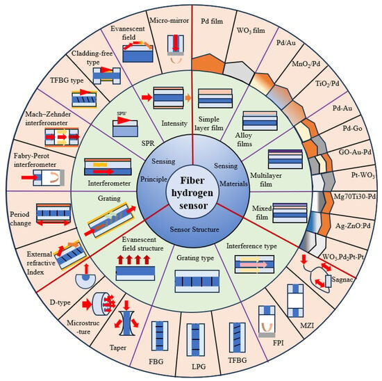
Figure 1.
Diagram of the typical fiber optic hydrogen sensor classifications.
2. Typical Fiber Optic Sensor Classification
2.1. Interference Fiber Optic Hydrogen Sensors
Most of the interference fiber optic hydrogen sensors rely on the principle of the interference of the light in fiber, including the Mach–Zehnder interferometer, Michelson interferometer, Fabry–Perot interferometer, and so on.
In 1984, Butler [5] proposed a Mach–Zehnder interference fiber optic hydrogen sensor. The fiber optic hydrogen sensor head was fabricated by coating a 10 μm-thick palladium film on the surface of the single-mode fiber (SMF) that was used as a signal arm. A layer of 10 nm-thick titanium film was coated between the palladium film and the surface of the fiber to increase the adhesion between the palladium film and the fiber. Figure 2 shows the sensor’s structure. As the fiber coated with the palladium film as a signal arm was exposed in the hydrogen environment, the palladium film absorbed the hydrogen and expanded, which makes the fiber tensile and changed the optical path of the incident light. The sensor could detect the hydrogen concentration in the range of 0.002 to 2000 Pa [6].
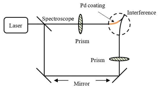
Figure 2.
Interference fiber optic hydrogen sensor based on Mach–Zehnder interferometer [5].
In 1986, Farahi [7] reported a Michelson interference fiber optic hydrogen sensor. The fiber optic hydrogen sensor head was fabricated by coating a palladium wire on the surface of an SMF with epoxy resin. The length and diameter of the palladium wire was 0.06 m and 0.5 mm, respectively. The end face of the sensing head was coated with silver to increase the intensity of the reflected light. The structure of the sensor is shown in Figure 3. When the hydrogen concentration increased, the palladium film absorbed the hydrogen and swelled, which would strain the fiber and cause a phase difference between the two signals. The variation of interference dip intensity is determined by the hydrogen’s concentration. The sensor can detect the hydrogen concentration in the range of 0 to 100 Pa, with an accuracy of ±2 Pa.
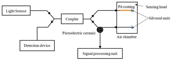
Figure 3.
Interference fiber optic hydrogen sensor based on Michelson interferometer [7].
In 1994, Zeakes [8] proposed a Fabry–Perot interferometer cavity hydrogen sensing probe. The structure of the sensor is shown in Figure 4. The SMF and a section of multi-mode fiber (MMF) that reflected light beams were fixed on both ends of the glass casing to form a Fabry–Perot cavity. The incident light was reflected on the end face of the SMF and the MMF, respectively. The length of the Fabry–Perot cavity was 50 μm. The surface of the glass liner was coated with 2 μm-thick palladium film. As the palladium film absorbed the hydrogen, the thin film would expand and cause a change of the length of the cavity and thus changed interference fringe phase. The maximum sensitivity of the sensors was 32 ppm.
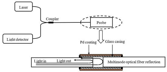
Figure 4.
Interference fiber optic hydrogen sensor based on Fabry–Perot interferometer [8].
In 2009, Zhen [9] proposed a fiber optic hydrogen sensor based on white light interference. As shown in Figure 5, the surface of the glass capillary was coated with 300 nm-thick palladium film. The interference light was reflected back from the probe and then propagated into the spectrometer. The hydrogen concentration could be monitored by using a cross-correlation method demodulation. In 2010, extrinsic Fabry–Perot fiber optic hydrogen sensors were proposed [10,11]. As the thicknesses of the palladium films were set as 50 nm and 100 nm, sensitivities of 2.07 nm/1% and 3.93 nm/1% H2 were obtained, respectively. However, as the hydrogen concentration was less than 1%, the actual sensitivities were decreased to 0.67 nm/1% and 1.28 nm/1% H2, respectively.
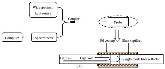
Figure 5.
Fiber optic hydrogen sensor based on white light interference [9].
The interference fiber optic hydrogen sensors showed the advantages of high sensitivity, short response time, and high reliability. And the sensitivities of these sensors can be adjusted by changing the length of the signal arm. However, these kinds of sensors showed a limitation on their applications (i.e., it can only measure the dynamic changes), and their accuracy also needed to be improved [12].
In 2015, Fu et al. [13] applied Pd/Au nanowires to a Mache–Zender interferometer (MZI) sensing system. As shown in Figure 6, the Pd/Au nanowires were utilized as plasmon waveguides connected in the sensing arm of the MZI, enabling the Surface Plasmon Resonance (SPRs) at the Pd/Au surface while sensing the hydrogen concentration. The interference spectrum of this sensor shows an extinction ratio of more than 20 dB, which ensures high hydrogen sensitivity and reversibility.

Figure 6.
Pd/Au nanowires based Mache–Zender interferometer hydrogen sensor [13].
In 2016, Xu [14] et al. proposed a highly sensitive optical fiber Sagnac interferometer hydrogen sensor (Figure 7). The device is fabricated by inserting a segment of panda fiber coated with Pt-loaded WO3/SiO2 into a Sagnac interferometer loop. When Pt/WO3 film is exposed to hydrogen, the exothermic reaction raises the temperature of the panda fiber, resulting in the resonant wavelength shift of the interferometer, and the resonant dip obtained has a large extinction ratio of ∼25 dB and a narrow linewidth of 2.5 nm.
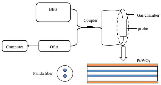
Figure 7.
Sagnac interferometer hydrogen sensor based on panda fiber with Pt-loaded WO3/SiO2 coating [14].
In 2021, Luo et al. proposed a fast-response FP hydrogen sensor (Figure 8) [15]. By splicing a single-mode fiber to a hollow core fiber and coating a graphene–gold–palladium film on the end face of the hollow core fiber, the FBG is inscribed in the single mode with femtosecond laser technology. The graphene oxide layer is applied to the hollow core fiber’s end face via wet transfer, and then gold and palladium are sputtered onto the graphene oxide layer using magnetron sputtering technique. The FBG will reflect a portion of the light satisfying the Bragg condition. The light beams reflected by FBG and graphene–gold–palladium would couple together. The sensor showed a response time of 4.3 s at a hydrogen concentration of 3.5% with a spectral contrast of 10.8 dB.
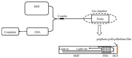
Figure 8.
FPI-based fiber optic hydrogen sensor with a graphene–Au–Pd and an FBG [15].
In 2021, Chen et al. [16] proposed a hydrogen sensor with high sensitivity, which was demonstrated by coating the metal organic frameworks of UiO-66-NH2 on an optical fiber Mach–Zehnder interferometer (MZI). The experimental setup of the UiO-66-NH2-based MZI hydrogen sensor is shown in Figure 9. The experimental results showed that the proposed sensor had a high hydrogen sensitivity of 8.78 dB/% in the range from 0% to 0.8%.
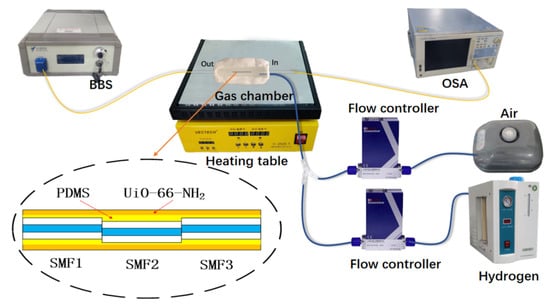
Figure 9.
Experimental setup of the UiO-66-NH2-based MZI hydrogen sensor; the partially enlarged portion shows the mismatched structure of the MZI [16].
In 2022, Lee et al. proposed an F-P structured hydrogen sensor for detecting hydrogen in a liquid state, which can detect hydrogen escaping from transformer oil due to mechanical damage (Figure 10) [17]. A single-mode fiber was attached to a glass cavity using a fiber optic hoop, and then the SiNx layer and Ti layer were modified sequentially to enhance the adhesion of the outermost Pd. The Pd layer and the glass cavity formed the sensing FPI. The glass layer and the fiber served as the temperature calibration. In addition, a micro-window was designed and located on the Pd-SiNx layer to relieve the extra stress brought by the detection of liquid. Under atmospheric conditions, the sensor showed a hydrogen sensitivity of 29.6 nm/% with a response time of 12.5 s.
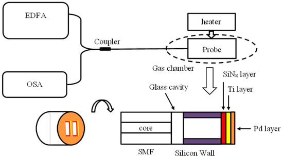
Figure 10.
Schematic of an F-P structured hydrogen sensor [17].
The sensing parameters of the above interference-based fiber optic hydrogen sensors are shown in the Table 1.

Table 1.
Sensing parameters of the interference-based fiber optic hydrogen sensors.
The interferometer hydrogen sensor has the advantages of easy manufacturing and straightforward design. However, their sensitivities and robustness are easily affected by external surrounding’s vibration and temperature variations.
2.2. Grating Fiber Optic Hydrogen Sensors
In 1999, Sutapun [18] proposed a hydrogen sensor based on fiber Bragg grating. The structure of the sensor is shown in Figure 11; the surface of the fiber Bragg grating was coated with 560 nm-thick palladium film. When the probe was surrounded by hydrogen, the palladium film would absorb the hydrogen and then swell, which would change the period of the fiber Bragg grating. The hydrogen concentration could be measured by detecting of the variation of the fiber Bragg grating’s resonant wavelength. When the hydrogen concentration was in the range of 0.5% to 1.4%, the sensitivity of this sensor was 1.95 × 10⁻² nm/%.
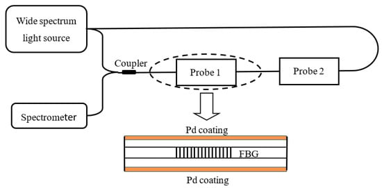
Figure 11.
Hydrogen sensor based on fiber Bragg grating [18].
In 2006, Troulillet [19] reported the hydrogen sensor based on a long-period fiber grating. The structure of the sensor is shown in Figure 12. One side of the long-period fiber grating was coated with palladium film with a length of 3 cm and a thickness of 50 nm. The hydrogen concentration could be detected by monitoring shifts of the resonant wavelength.

Figure 12.
Long-period fiber grating-type hydrogen sensor [19].
In 2008, Kim [20] reported the cascaded long-period fiber grating-type hydrogen sensor. The structure of the sensor is shown in Figure 13. The period and length of the long-period fiber gratings are 500 μm and 20 mm, respectively. The space between the two long-period fiber gratings is 50 mm. The surface of the cascaded long-period fiber grating was coated with a 50 nm thick and 70 mm-long palladium film. The hydrogen concentration could be measured by detecting the interference peak wavelength. The experimental results showed that the effective refractive index of the cladding modes was increased after the palladium layer absorbed the hydrogen. The interference spectrum showed a blue-shift. While working in the hydrogen with the concentration of 4%, the spectrum of the sensor moved to the shorter wavelength direction with a wavelength sensitivity of −0.29 nm/%.

Figure 13.
Cascaded long-period fiber grating-type hydrogen sensors [20].
In 2013, Silva [21] reported a tapered fiber grating-type hydrogen sensor based on Bragg fiber grating. As shown in Figure 14, the femtosecond laser technology was used to write the FBG fiber grating in a tapered fiber with a diameter of 50 μm. And then its surface was coated with 150 nm-thick palladium film. The second FBG fiber grating was written in the ordinary optical fiber with a diameter of 125 μm to realize the temperature compensation. The experimental results showed that at room temperature, the sensor could detect the hydrogen concentration in the range from 0% to 1% with a maximum sensitivity of 81.8 pm/%.
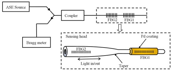
Figure 14.
Tapered fiber grating-type hydrogen sensors [21].
In 2015, Yu et al. proposed an ultra-fine micro-nano Bragg grating hydrogen sensor based on palladium coating (Figure 15) [22]. An FBG grating was inscribed into an ultrafine fiber with a diameter of 3.3 μm. And then the FBG surface was coated a Pd film with a thickness of 220 nm by using the magnetron sputtering means. Under a hydrogen concentration of 5%, the reflection peak of FBG changed approximately 1.08 nm with a response time of 60 s.
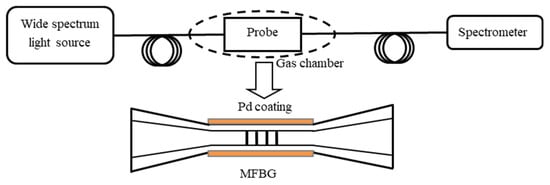
Figure 15.
Schematic of the microfiber FBG hydrogen sensor [22].
Dai et al. in 2022 proposed a compact fiber optic hydrogen sensing system based on a self-referencing structure of FBG with controlled heating technology (Figure 16) [23]. The sensing probe was fabricated with a nano-WO3-Pd2Pt-Pt film with a double FBG mosaic, which worked by relying on the aero chromic effect of the hydrogen-sensitive film. The peak intensity and the background intensity of the highly reflective FBG worked as the reference intensity and the sensed intensity, respectively. The experimental results showed that the sensor can work stably in the range of 1–1000 ppm of hydrogen at 80 °C. The resolution of this hydrogen sensing system can reach up to 0.2 ppm. Meanwhile, the sensor achieved a fast response of less than 1 s for a concentration of 4000 ppm of hydrogen in air.
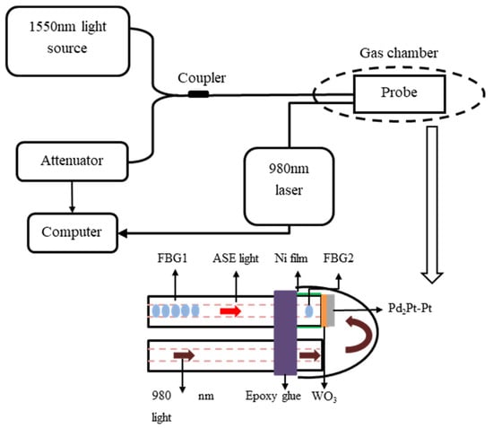
Figure 16.
Schematic diagram and sensing mechanism of the sensing probe [23].
Recently, a new Bragg grating hydrogen sensor with palladium coating (Figure 17) has been proposed by Buchfellner [24]. A 10 mm-long Bragg grating with pi shift (PSFBG) is coated with palladium with a length of 4 mm. As the Pd coating length is smaller than the PSFBG length, the flanking wavelengths of the wide reflection band are temperature-sensitive, while the notch wavelengths of the narrow transmission band are hydrogen-sensitive due to the strain caused by hydrogen absorption of Pd changes part of the grating period. The sensor can be self-calibrated for temperature change at hydrogen concentrations of 800–10,000 ppm.
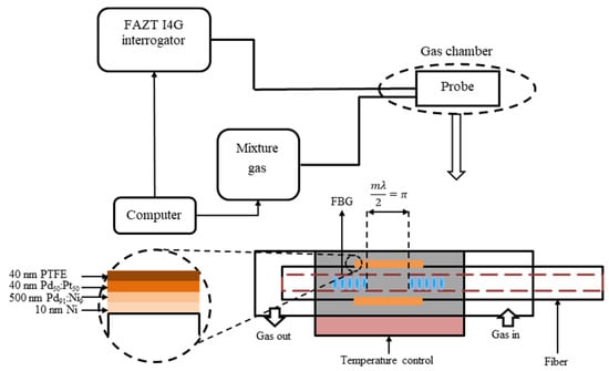
Figure 17.
Schematic of a partly Pd-coated Pi-shifted FBG hydrogen sensor [24].
In 2021, Zhang et al. [25] proposed a tilted fiber Bragg grating (TFBG) hydrogen sensor based on Pd/Au composite nanofilms, as shown in Figure 18. Pd and Au films with thickness of 25 nm and 35 nm were deposited on the surface of TFBG by the magnetron sputtering method. The experimental results illustrated that when the hydrogen concentration changes from 0% to 1.02%, the intensity of cladding mode resonant wavelength (1558.4 nm for instance) decreases by 1.628 dB, and the hydrogen concentration sensitivity of 1.597 dB/% was obtained. The average response and recovery time were 37 s and 49 s, respectively.

Figure 18.
Schematic diagram of the proposed Pd/Au nanofilms-coated TFBG hydrogen sensor [25].
In 2021, as shown in Figure 19, Zhang et al. [26] proposed a hydrogen sensor based on tilted fiber Bragg grating (TFBG) coated with polydimethylsiloxane (PDMS)/WO3 composite film. The WO3 powder can be adhere well to the surface of TFBG by the flexible PDMS film, and the proposed fiber hydrogen sensor showed the sensitivity of 0.596 dB/% under the hydrogen concentrations from 0% to 1.53%. The average response time and recovery time of the sensor were 93 s and 107 s, respectively.
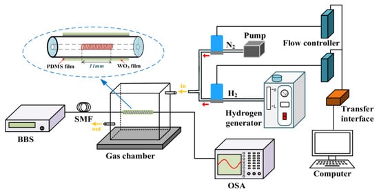
Figure 19.
Schematic diagram of the TFBG hydrogen sensor [26].
In 2022, Shen et al. [27] proposed a highly sensitive reflective-type fiber hydrogen sensor based on an enlarged taper cascaded with a tilted fiber grating (TFBG), as shown in Figure 20. Hydrogen-sensitive Au-Pd nanofilm was coated on the TFBG surface by magnetron sputtering means. By cascading an enlarged taper upstream to the TFBG, cladding modes and Ghost mode of the TFBG could be coupled into the core to form a reflective-type TFBG-based hydrogen sensor. The proposed sensor showed a high sensitivity of 4.83 dB/% with a calculated LOD of 0.07% for the hydrogen concentration range from 0% to 0.7% at room temperature with the rapid response time of 26 s and recovery time of 40 s, respectively.

Figure 20.
The specific structure of the sensing head [27].
The sensing parameters of the above optical fiber grating-based hydrogen sensors are shown in the Table 2.

Table 2.
Sensing parameters of the grating-based fiber optic hydrogen sensors.
The hydrogen sensor based on grating fiber offers significant advantages in distributed measurement and temperature correction due to its own sensing mechanism. Consequently, fiber grating-based hydrogen sensors typically have higher accuracy. However, the fiber Bragg grating hydrogen sensor needs to be stripped of the coating layer during production, and part of the fiber cladding needs to be corroded to reduce its grating diameter to obtain higher sensitivity, which will greatly weaken the mechanical strength of the fiber Bragg grating hydrogen sensor.
2.3. Surface Plasma Resonance (SPR) Fiber Optic Hydrogen Sensors
In 1993, as shown in Figure 21, Chadwich [28] proposed an SPR hydrogen sensor. The surface of the inverted prism was coated with palladium/nickel alloy. When the polarized light enters the interface between glass and medium at an angle exceeding the critical angle, total reflection occurs. At the interface between the two media, evanescent waves are generated, and SPR occurs when the dielectric constants of the metal and glass meet certain conditions, and the effective refractive index expression that can generate SPR can be expressed as,
where NSPR is the effective refractive index of the surface plasma wave, εM is the dielectric constant of the plated metal film, and ns is the effective refractive index of the external environment of the metal film. Theoretically, once the thickness of the metal film is determined, the resonance wavelength of the SPR it can excite completely depends on the refractive index of the environment in which it is located. When Pd absorbs hydrogen gas, its dielectric constant changes, which affects the SPR spectrum. For this sensor, the lowest hydrogen concentration that could be detected was 0.15%.
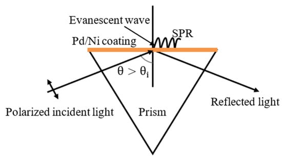
Figure 21.
Surface plasma resonance sensor structure [28].
In 1998, Benson [29] proposed a Pd/WO3 film-based fiber optic hydrogen sensor by using an SPR means. The sensitivity and the response speed of the proposed hydrogen sensor are improved. However, its stability was affected by the water vapor on the surface of WO3. In 2004, Hu [30] proposed a Pd/Au composite film SPR-based hydrogen sensor. Compared with the single Pd film-based hydrogen fiber sensor, this sensor showed good reliability, high sensitivity, and good responsivity. Compared to the single Pd (20 nm) film hydrogen sensor, the highest sensitivity of the Au (2 nm)/Pd (20 nm) composite film hydrogen sensor increased by 49.4%.
In 2011, Zhang [31] reported an SPR fiber optic hydrogen sensor, in which the sensor probe was fabricated with the Pd/Ag composite film on a side polished fiber type “D”. The effective refractive index of the side polished fiber SPR mode increased with the increasing of the refractive index of the sensing area and decreasing with increasing of the thickness of the cladding material. This kind of fiber optic hydrogen sensor based on Pd/Ag composite film can improve the stability and sensitivity in hydrogen monitoring.
In 2015, as shown in Figure 22, Tabassum et al. [32] proposed a silver-based fiber optic cladding-free SPR hydrogen sensor. The cladding-free core was first coated with silver (Ag) and then coated with palladium-doped zinc oxide nanocomposite, to fabricate a hydrogen sensing probe. When the probe absorbed hydrogen, the dielectric constant of the composite changed, resulting in a drift of the SPR spectral. As the hydrogen concentration changed from 0% to 4%, the SPR resonant wavelength showed a red-shift, and the response time of the sensor was about 1 min.
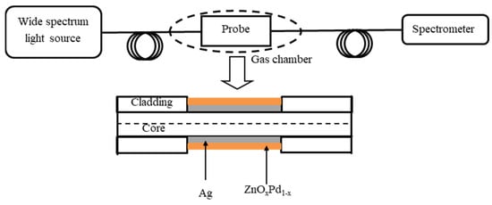
Figure 22.
The specific structure of the sensor [32].
In 2018, Zhang et al. [33] used a large-angle tilted fiber grating to excite SPR in air to detect hydrogen concentration. As shown in Figure 23, the SPR was excited by plating 30 nm gold film on a 23-degree tilted fiber grating. Then, a palladium film with a thickness of 7 nm was coated on the gold film. The experiment results showed a linear relationship between hydrogen concentration and SPR mode change at hydrogen concentration range from 0% to 1.7%. The sensitivity was −0.15 dB/% with a detection limitation of 380 ppm. In 2019, Cai et al. [34] plated a 60 nm-thick Pd film on the surface of TFBG, which had a tilt angle of 10 degrees, as the SPR hydrogen sensing head. The experimental results showed that the SPR mode changed by 0.4 dB while the hydrogen concentration changed from 0% to 0.4%. The response time was approximately 3 min with a detection limit of 0.018%.
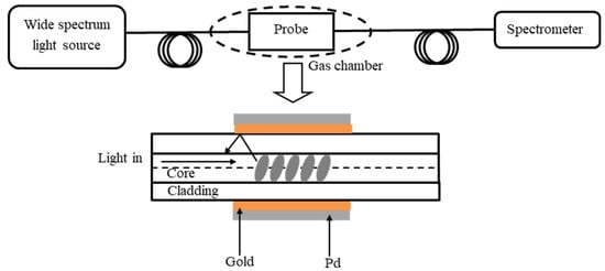
Figure 23.
The sensing system structure [33].
The sensing parameters of the above SPR-based fiber optic hydrogen sensors are shown in Table 3.

Table 3.
Sensing parameters of the SPR-based fiber optic hydrogen sensors.
SPR-type fiber optic hydrogen sensors show high sensitivity. However, most of the sensing spectral range of the SPR hydrogen sensor are located in the near-infrared band, thus there are specific equipment requirements. Additionally, the most crucial metal coating for SPR activation likewise necessitates pricey machinery, making the production of SPR sensors expensive.
2.4. Micro Lens Fiber Optic Hydrogen Sensors
In 1991, Butler [35] proposed a micro-lens fiber optic hydrogen sensor. The structure of the sensor was shown in Figure 24. The end of the MMF was coated with 10 nm thick palladium film. The fiber core and cladding diameter were 50 μm and 125 μm, respectively. The light emitted from the light source propagated to the sensing head via the coupler and was reflected at the end face of the MMF. The reflected light went through the coupler and came back to the detection device. The refractive index and the reflectivity of the palladium film changed due to the hydrogen absorption, which caused the intensity changes of the output light. By detecting the output intensity change, the hydrogen concentration variation could be measured.
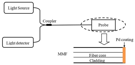
Figure 24.
Micro lens-type fiber optic hydrogen sensor [35].
In 1998, Chuck [36] coated the palladium film and palladium alloy film on the end of the optical fiber, forming a thin film etalon. The palladium film etalon-based sensor showed good repeatability in low hydrogen concentration measurement. In 1999, Kazemi [37] tested the response capability of the micro lens sensor at −18 °C to 122 °C. They found that the response time of hydrogen detection was inversely proportional to temperature; the lower the temperature, the longer the response time. And the response time changed significantly as the hydrogen concentration was less than 1%. In 2000, Bevenot [1] proposed a micro-lens-type fiber optic hydrogen sensor with a response time of 5 s under the hydrogen concentration range of 1% to 17%. And it could realize a rapid detection of the hydrogen concentration below the explosion limit. And increasing the environment temperature could reduce the reaction time. In 2007, Slaman et al. [38] reported a fiber optic hydrogen sensor based on a chemically plasmonic color-changing metal oxide coating (as shown in Figure 25). A 50-nm-thick Mg70Ti30 film was coated at the end of a multimode fiber as a switchable mirror, and then a 30-nm Pd was coated on the Mg70Ti30 film to use as the sensing layer. Finally, a protective coating was coated on the Pd film to protect the sensor. The magnesium-based alloy good hydrogen-sensitive achromatic properties allow it to be rapidly reduced by a factor of ten at a hydrogen concentration of about 4%. The sensor showed good cyclability as well as a fast hydrogen response rate.
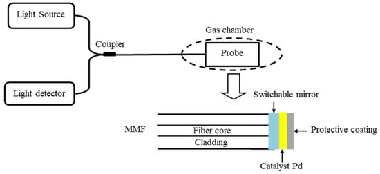
Figure 25.
Layout of the fiber optic hydrogen detector [38].
In 2011, Park et al. [39] proposed a dual-cavity structure optical fiber hydrogen sensor, as shown in Figure 26. The sensing cavity was fabricated by plating a 20 nm-thick Pd film on the end of a single-mode fiber, and then a hollow fiber with a length of 35 μm was inserted upstream of the single-mode fiber to form a reference cavity. When Pd absorbed hydrogen, the intensity of the reflection peak on the interference spectrum decreased. The reflection peak associated with the reference cavity could compensate the power fluctuation of the light source.
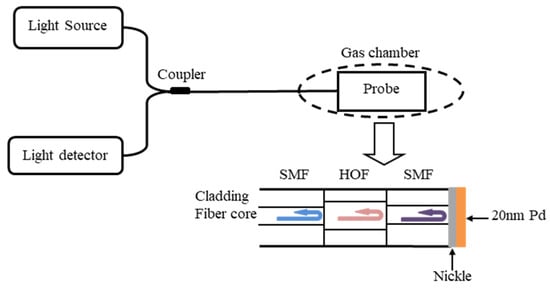
Figure 26.
Schematic of the dual-cavity hydrogen sensor [39].
In 2019, Xu et al. [40] proposed a polarization-modulated fiber optic reflective hydrogen sensing system, as shown in Figure 27. The hydrogen sensing probe consisted of a polarization-maintaining fiber (PMF) coated with Pt-WO3. When Pt-WO3 absorbed hydrogen and released heat, the temperature of the PMF increased, causing a polarization state change of the PMF. This resulted in a shift of the reflection spectrum. A sensitivity of 18.04 nm/% in the range of 0–4% hydrogen concentration with high repeatability was obtained.
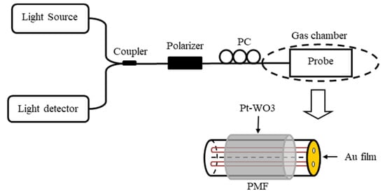
Figure 27.
Diagram of the polarization-modulated fiber optic reflective hydrogen sensor [40].
The sensing parameters of the above micro-lens-based fiber optic hydrogen sensors are shown in the Table 4.

Table 4.
Sensing parameters of the micro-lens-based fiber optic hydrogen sensors.
The micro lens-type fiber optic sensors have a simple structure and are easy to fabricate, which make the micro lens-type fiber optic sensor suitable for commercial use. However, due to its characteristics based on light intensity sensing, it is extremely sensitive to both light source disturbance and fiber loss.
2.5. Fiber Optic Evanescent Field Hydrogen Sensors
When the incident light propagates to the interface between two kinds of materials with different refractive index, the distribution of light field satisfies the boundary conditions of the electromagnetic field, thus there are light field in both of the materials. Studies showed that when the incident angle and the refractive index of the small refractive index material changed, the effective penetration depth of the transmitted wave in the medium will change, which is the basic principle of the evanescent field fiber optic hydrogen sensor [41]. Theoretical analysis showed that when the wavelength of the input light increases or the refractive index of the sample to be measured becomes higher (close to the core refractive index value for instance), the depth of the evanescent field will also increase. And when the incident angle is equal to the critical angle of total reflection, the transmission depth will reach its maximum value [42].
A typical fiber optic evanescent field hydrogen sensor’s structure is shown in Figure 28. The fiber cladding was stripped and coated with a layer of hydrogen-sensitive film. The evanescent wave could be excited and propagated between the fiber core and the boundary of the hydrogen-sensitive film. The sensor showed good repeatability, but its responsiveness and recoverability were greatly influenced by the humidity of the environment. Compared to the traditional sensors, which could only be used to measure the hydrogen concentration at one point or few points, the evanescent field fiber optic hydrogen sensor could be used to measure the hydrogen concentration in three-dimensional space.
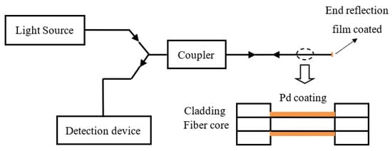
Figure 28.
Evanescent-field-type fiber optic hydrogen sensor.
2.5.1. D-Type Fiber Optical Hydrogen Sensors
D-type fiber is a kind of fiber with a D-shaped end face, which can be obtained through fiber polishing or corrosion, as shown in Figure 29. Due to its unique structure, the evanescent wave generated on the interface between the fiber core and the environment can interact directly with the gas or interact indirectly with the gas through the sensitive film coated on the surface. The gas concentration can be measured by the change of the output optical signal of the sensor.
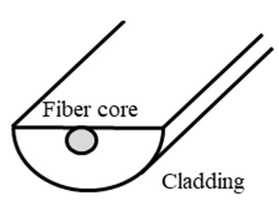
Figure 29.
Schematic of the D-type fiber optic sensor.
In 2010, Liu [43] proposed an evanescent wave-based hydrogen sensor by coating with the Pd and Pd/WO3 on the surface of a D-type optical fiber. As shown in Figure 30, the sensing system consisted with a stable light source, optical power meter, hydrogen detector and a gas chamber. The sensing probe was sealed in the gas chamber. A high degree of linear correlation between the optic power and the concentration of the hydrogen with good reproducibility were obtained.
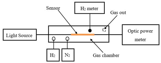
Figure 30.
Pd and Pd/WO3 based D-type optical fiber hydrogen sensor [43].
In 2015, as shown in Figure 31, Yan [44] reported on an ultra-high temperature fiber optical chemical sensor based on nano-porous metal oxides. Nano-porous functional metal oxides and their doped variants were prepared through a solution-based approach and were integrated into a D-shaped silica fiber Bragg grating. By detecting the wavelength peaks of the Bragg grating, the refractive index change and optical absorption loss due to the redox reaction that occurred between Pd-doped TiO2 and hydrogen were monitored in the temperature range from room temperature to 800 °C. The response time was less than 8 s.
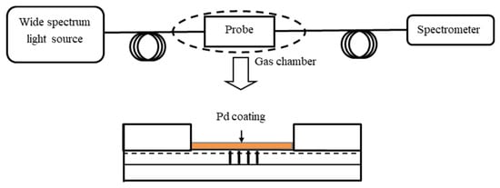
Figure 31.
Experiment setup of the sapphire fiber-based sensor [44].
In 2016, as shown in Figure 32, Poole [45] reported a distributed high-temperature sensor based on a D-shaped optical fiber Bragg grating modified with a palladium-sensitized mesoporous (~5 nm) TiO2 film. The distributed sensor had potential for hydrogen concentrations detection up to 10%, and it could be worked at temperatures higher than 500 °C.
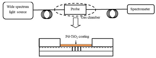
Figure 32.
D-shaped optical fiber Bragg grating modified with a TiO2 hydrogen sensor [45].
In 2019, as shown in Figure 33, Cao et al. [46] presented an optical fiber hydrogen sensor by using palladium and gold alloy nanostructures as the sensing material coated on a D-shaped optical fiber. A silicon dioxide nanotip structure was formed on the surface of the D-shaped fiber. Palladium and gold alloy were deposited on the nanotip structure of the D-shaped fiber to form a nano-alloy sensor film. The interaction of attenuation between the guided light propagating in the fiber core and the nano-alloy enables high-sensitivity detection of hydrogen in the concentration range of 0.25% to 10% under atmospheric pressure.
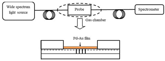
Figure 33.
Palladium and gold alloy nanostructures based D-shaped optical fiber hydrogen sensor [46].
The sensing parameters of the above D-type fiber-based hydrogen sensors are shown in the Table 5.

Table 5.
Sensing parameters of the D-type based fiber optic hydrogen sensors.
D-shaped fiber is sensitive to external refractive index changes, which makes the structure have a high sensitivity. However, due to the removal of a lot of cladding in the production process of the D-shaped structure, the structure is extremely fragile and easy to be broken by lateral forces.
2.5.2. Tapered Fiber Hydrogen Sensors
The tapered optical fiber is a type of optical fiber that features a gradual change in diameter along its length, as depicted in Figure 34. It can be fabricated by employing the corrosion method or fused taper method. The sensing principle is based on the interaction of the evanescent wave in the vicinity of the conical region with the gas either directly or indirectly through the sensitive film coated on the conical area, which causes a change in the penetration depth of the evanescent wave. Subsequently, the change in the output optical signal of the sensor can be utilized to measure the concentration of unknown gases. A reduction in the diameter of the conical waist, coupled with an increase in the incident wavelength, leads to an improvement in the sensor’s sensitivity and resolution.

Figure 34.
Schematic of the tapered fiber sensor.
In 2001, Villatoro [47] conducted a study on tapered fiber hydrogen sensors coated with an annular palladium film. The sensor was immune to polarization, and its sensitivity could be adjusted by modifying the tapered diameter, length, and optical wavelength [48]. The output optical power of the sensor changed by 60% when the hydrogen concentration was below 4% with a rapid hydrogen absorption/desorption rate. Additionally, when a thin palladium film was deposited on a 1.3 μm diameter and 2 mm-long tapered SMF, the hydrogen sensor showed excellent reversibility, reduced response time of 10 s, which was several times faster than the conventional sensor. In 2005, Villatoro [49] coated a palladium film on a single-mode or multimode tapered fiber or fiber Bragg grating with a polished side. The single-mode tapered fiber sensor demonstrated the best sensitivity when the hydrogen concentration was 4%. Furthermore, Villatoro [50] fabricated the multimode tapered fiber by oscillation flame heating and utilized a low-power 850 nm LED as the light source. By altering the taper waist diameter with uniform palladium film, the sensor’s response time could be adjusted. The sensor was particularly suitable for detecting hydrogen concentrations below 4%, exhibiting high sensitivity with a response time of 40 s. In 2006, Zalvidea [51] reported an experimental study on palladium-coated tapered optical fibers within a temperature range of −30 °C to +80 °C. They investigated the response time and initial response velocity and correlated these measurements with the pressure–composition isotherms of the Pd-H system and its phase transitions. A 25 μm tapered waist and 8 mm-long tapered optical fiber sensor demonstrated the most substantial response speed when the temperature was −30 °C and the hydrogen concentration was below 4%. In 2017, Yahya [52] reported a novel hydrogen sensor by coating a manganese dioxide (MnO2) nanostructure on a multimode fiber taper with a reduced core diameter of 20 μm, as shown in Figure 35. MnO2 nanoparticles were synthesized using a chemical bath deposition (CBD) method and then coated onto the tapered fiber. To enhance H2 detection, palladium was sputtered onto the MnO2 layer.
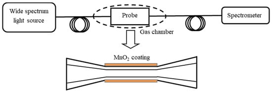
Figure 35.
Multimode fiber taper based gas sensing experimental setup [52].
In 2022, Alkhabet et al. [53] reported an MMF taper hydrogen sensor by using a palladium/graphene oxide (Pd/GO) nanocomposite coating as a sensing layer, as shown in Figure 36. The sensitivity of 33.22/vol% with a response time of 48 s and a recovery time of 7 min were obtained under the H2 concentration range from 0.125% to 2.00%. The sensor also exhibited good selectivity and stability.
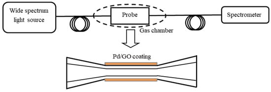
Figure 36.
Sketched of tapered fiber coated with Pd/GO hydrogen sensor [53].
The sensing parameters of the above tapered fiber-based hydrogen sensors are shown in the Table 6.

Table 6.
Sensing parameters of the tapered fiber-based optic hydrogen sensors.
2.5.3. Bare Core Fiber Optic Hydrogen Sensors
As shown in Figure 37, the bare core fiber sensor structure could be obtained by removing the cladding of the ordinary fiber. The sensing principle involves the evanescent wave near the surface of the bare fiber core interacting directly with the gas or indirectly through the sensitive film coated on the surface of the bare fiber core. The depth of the evanescent wave changes due to this interaction. Consequently, the unknown gas concentration could be measured by observing the change in the output optical signal of the sensor.

Figure 37.
Bare core fiber optic hydrogen sensors.
In 1999, Sutapun [18] deposited a palladium film with a thickness of 10 nm to 20 nm onto the surface of a multimode bare fiber. At room temperature, the sensor could detect hydrogen concentrations ranging from 0.2% to 0.6%, with a response time of 20 s to 30 s. In 2000, Sekimoto [54] altered the cladding of the fiber to change the intensity of the evanescent field using two methods: (1) coating the fiber with a dispersed Pd/WO3 silicone resin as the cladding; (2) using the Pd/WO3 sol as the cladding. When WO3 encountered hydrogen, it generated tungsten bronze, which absorbed a significant amount of the evanescent field. In 2003, Okazak [55] coated WO3 containing platinum/palladium catalyst on the bare optical fiber core of a 200/230 μm plastic clad silica fiber. The sensor’s output optical power could be reduced by 75% when the hydrogen concentration was at 1%. Furthermore, in 2005, Villatoro [56] deposited a palladium film on a multimode bare fiber core, forming an evanescent wave hydrogen sensor. The sensor exhibited high sensitivity and a fast response speed when the hydrogen concentration was within the range of 0.5% to 3%. In 2007, Zhao [57] removed the MMF cladding by using a corrosion method and coated a 20 nm or 30 nm palladium film on the surface of the fiber. The sensor could detect hydrogen concentrations between 1% and 4%.
In 2021, Dai [58] reported an optical fiber hydrogen sensor based on a WO3-Pd2Pt-Pt nanocomposite film, as shown in Figure 38. The WO3-Pd2Pt-Pt nanocomposite film was deposited on a single-mode fiber as the hydrogen sensing material, and its reflectivity changed in response to varying hydrogen concentrations. A pair of balanced InGaAs photodetectors were employed to detect these reflectivity changes and convert them into electrical signals. The performance of the WO3-Pd2Pt-Pt composite film was examined under different optical powers, and the results demonstrated a high resolution of 5 ppm (parts per million) within a broad range of 100–5000 ppm in air.
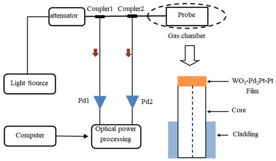
Figure 38.
Schematic of the WO3-Pd2Pt-Pt based optical fiber hydrogen sensing system [58].
The sensing parameters of the above bare core fiber-based hydrogen sensors are shown in the Table 7.

Table 7.
Sensing parameters of the bare core fiber-based hydrogen sensors.
Compared with D-shaped fiber and tapered fiber, the bare core fiber hydrogen sensor removes all thin layers in the sensing area, which greatly improves the sensing accuracy of the sensor. However, this characteristic also renders the sensor’s vibration resistance and mechanical strength.
2.5.4. Core Mismatch Type Fiber Optic Hydrogen Sensor
The core mismatch type fiber optic sensor is a novel evanescent wave sensor that involves welding the two ends of the SMF into the MMF, respectively, as shown in Figure 39 [59]. The evanescent wave near the SMF cladding (sensing area) could directly interact with the gas or indirectly interact with the gas through the sensitive film coated on the surface of the SMF cladding, resulting in a change in the penetration depth of the evanescent wave. By monitoring the change in the output optical signal of the sensor, the gas concentration could be measured.
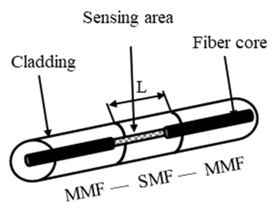
Figure 39.
Core mismatch type fiber optic hydrogen sensor [59].
In 2007, Donato [60] proposed a core mismatch type fiber optic sensor with an MMF-SMF-MMF structure. A 10 nm-thick film of either pure palladium or palladium–gold alloy was deposited on the SMF sensing area. The sensor exhibited good sensitivity, robustness, and reversibility with a response time of less than 15 s. In 2017, Shao [61] et al. spliced an SMF to a coreless fiber, and then attached another SMF to create a core mismatch interferometric structure (Figure 40). They coated a Pd/WO3 film on the surface of the coreless fiber to serve as a hydrogen-sensitive region. The refractive index of the Pd/WO3 film changes as a result of varying hydrogen concentrations, leading to a shift in the interference spectrum. The hydrogen sensitivity of 1.26857 nm/% was obtained.
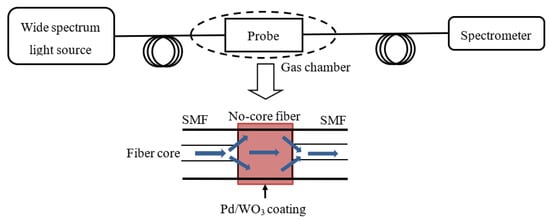
Figure 40.
Specific structure of SNS sensing structure [61].
In 2018, Zhang et al. [62] proposed an SMF-MMF-SMF interferometric structure. They wrapped a Pd/WO3 film around the SMS structure to create a hydrogen sensing head (Figure 41). When combined with an erbium-doped fiber ring laser, the sensing head was utilized for bandpass filtering. Changes in hydrogen concentrations cause alterations in the refractive index and strain of Pd/WO3, which subsequently result in a drift of the interference spectrum. The hydrogen sensitivity of 1.23 nm/% with a lower detection limit of 0.017% were obtained.
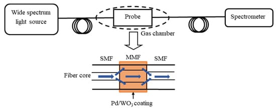
Figure 41.
Schematic structure of SMS modal interferometer with Pd/WO3 coating [62].
The sensing parameters of the above core mismatch fiber optic hydrogen sensors are shown in the Table 8.

Table 8.
Sensing parameters of the core mismatch fiber optic hydrogen sensors.
The advantage of the core mismatch type of fiber optic hydrogen sensor is that it does not weaken the mechanical strength of this type of sensor while remaining sensitive to the external environment.
2.5.5. Microstructure Fiber Optic Hydrogen Sensor
Microstructure optical fiber (MOF), also known as photonic crystal fiber or porous fiber, was first proposed by Russell in 1992 [63]. This type of optical fiber is composed of tiny air holes arranged in a regular pattern along the axial direction around the core. These small air holes confine the light, enabling its conduction, as illustrated in Figure 42.
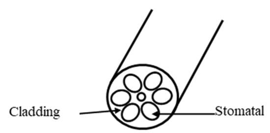
Figure 42.
Microstructure fiber optic hydrogen sensor [63].
Compared to conventional optical fibers, MOFs exhibit no single-mode cutoff, distinct chromatic dispersion properties, exceptional nonlinear and birefringence effects, high incident power, and nonlinear phenomena specific to photonic crystal fibers. Moreover, they facilitate multi-core transmission. The sensing principle involves the target gas changing the effective index of the cladding, which in turn alters the penetration depth of the evanescent wave at the core interface. Sensing can be achieved by measuring changes in the transmitted light signal within the fiber core. By coating various types of gas-sensitive film materials within the pores, the sensitivity of the sensor can be improved.
In 2003, Hoo [64] presented a highly sensitive and practical sensor based on the theoretical analysis of the diffusion kinetic behavior of micro-structured fiber optic gas sensors during the response process. In 2004, Ritari [65] proposed an air-guided photonic bandgap fiber gas sensor for detecting acetylene, hydrogen, and hydrogen cyanide. This sensor exhibited high sensitivity and also responded to methane and ammonia. In 2006, Minkovich [66] developed a novel evanescent wave fiber optic gas sensor by coating a sensitive film on the defect hole of a tapered micro-structured optical fiber. The sensor demonstrated a fast response time, as the gas did not need to completely fill the pore. The interaction between the palladium film and hydrogen validated its feasibility. Cordeiro CMB [67] introduced a micro-structured fiber optic gas sensor based on total internal reflection of light. In 2007, Ho [68] analyzed the relationship between air hole spacing parameters and the confinement loss, as well as the sensitivity of gas detection in micro-structured fibers. As the confinement loss was 0.1 dB/m and 1 dB/m, the maximum relative sensitivity of the sensor ranged from 30% to 35% was obtained. In 2014, Wang [69] proposed a sensitive hydrogen sensing device based on a selectively infiltrated photonic crystal fiber (PCF) coated with Pt-loaded WO3 (Figure 43). With Pt-loaded WO3 coating acting as the catalytic layer, hydrogen undergoes an exothermic reaction with oxygen and releases heat when the device is exposed to gas mixtures of air and hydrogen, which induces local temperature change in the PCF and hence leads to the resonant wavelength shift of the proposed device. The maximum wavelength shift of 98.5 nm is obtained with a 10-mm-long infiltrated PCF for 4% (v/v) H2 concentration, and a hydrogen sensitivity of 32.3 nm/% (v/v) H2 is achieved within the range of 1–4% (v/v) H2 in air.
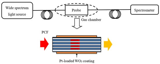
Figure 43.
Schematic structure of PCF coated with Pt-loaded WO3 fiber optic hydrogen sensor [69].
The sensing parameters of the above microstructure-based fiber optic hydrogen sensors are shown in the Table 9.

Table 9.
Sensing parameters of the microstructure based fiber optic hydrogen sensors.
2.6. Integrated Optical Waveguide Fiber Optic Hydrogen Sensors
In 1992, Bearzotti [70] constructed a Mach–Zehnder interferometer using a lithium niobate single-mode waveguide coated with palladium film, as depicted in Figure 44. When the palladium film absorbed hydrogen, the refractive index changed, leading to a phase shift of the light within the waveguide. This phase shift could be detected by observing changes in the intensity of the output light.
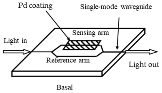
Figure 44.
Waveguide fiber optic hydrogen sensor based on the Mach–Zehnder interferometer [70].
Another type of optical waveguide hydrogen sensor involves coating a lithium niobate waveguide with Pd and WO3 as the sensing layer. The propagating light interacts with the layered Pd/WO3 through the evanescent wave. By comparing the light intensity between the sensing arm and the reference arm, the hydrogen concentration can be detected [71]. In 2001, Hugon [72] developed a waveguide sensor based on surface plasmon resonance (SPR), as illustrated in Figure 45. The palladium film coated on the surface of a single-mode strip waveguide served two purposes: one was as a photochemical sensor, and the other was as a support for the surface plasmon wave (SPW). The hydrogen content in the palladium film varied with the hydrogen concentration, influencing the interaction between the guided wave mode and the SPW. The sensor was capable of detecting hydrogen concentrations below 4%.
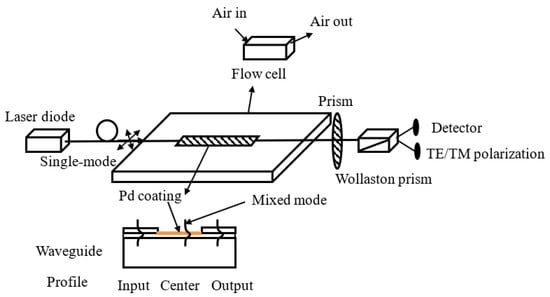
Figure 45.
Integrated fiber optic hydrogen sensor based on the SPR [72].
The sensing parameters of the above integrated optical waveguide fiber optic hydrogen sensors are shown in the Table 10.

Table 10.
Sensing parameters of the integrated optical waveguide fiber optic hydrogen sensors.
The integrated optical waveguide fiber optic hydrogen sensor offers advantages such as high sensitivity, accurate information, compact size, and the potential for mass production. Its primary drawback, however, is the difficulty in achieving an effective, low-loss connection between the SMF and the waveguide.
2.7. Direct Transmission/Reflection-Type Fiber Optic Hydrogen Sensor Measurement
A straightforward method for detecting hydrogen with a sensor involves directly measuring the transmission and reflection data of the palladium film, as Mandelis [73] and Wan [74] developed in Figure 46. When the palladium film was exposed to hydrogen, the transmission intensity increased while the reflection intensity decreased. In transmission mode, optimal output intensity and sensitivity were achieved with a palladium film thickness between 10 and 20 nm. As the thickness of the palladium film exceeded 45 nm, the palladium film became non-transparent and could only be used in reflection mode.
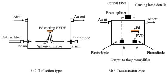
Figure 46.
Fiber optic hydrogen sensor based on transmission/reflection measurement. PVDF: polyvinylidene difluoride, PVD: physical vapor deposition [73,74].
In 2001, Chtanov [75] presented an MgF2/Pd/Au/SiO2 multi-film structure hydrogen sensor. The stray effects, false readings, and drifts in the monolayer film sensor were eliminated by utilizing the differences in optical transmission characteristics between various films. In 2013, Zhou [76] introduced a new hydrogen sensor based on a photonic crystal fiber (PCF) interferometer. This sensor used a reflective light path and incorporated a PCF in the hydrogen sensing unit. A layer of metal palladium film was coated on one end of the PCF and part of the cladding wall under vacuum evaporation. The other end of the PCF was connected to the optical path, forming a fiber optic hydrogen sensor system. Experimental results demonstrated that with a hydrogen concentration change from 0 to 5%, the maximum shift of the interference resonant wavelength could reach 1.2 nm. Compared to the most fiber Bragg grating-based hydrogen sensors, the sensitivity was significantly improved under the same conditions.
In addition, the attenuation spectrum change of optical fiber in the state of high concentration of hydrogen also provides a new method to detect hydrogen. Stone [77] summarized the effects of hydrogen on silicon-based optic fibers. Exposure of fibers to hydrogen results in a certain amount of the gas being dissolved in the glass interstices. Due to interaction with the glass lattice, the gas becomes infrared active and there is intense absorption in the transmission window of fibers. This provided a way for fiber optic sensors to detect high concentrations of hydrogen. In 2022, Stolov [78] further proved this method.
The sensing parameters of the above direct transmission/reflection-type fiber optic hydrogen sensors are shown in Table 11.

Table 11.
Sensing parameters of the direct transmission/reflection-type fiber optic hydrogen sensors.
The direct transmission/reflection measuring-type fiber optic hydrogen sensor has a simple structure, and its fabrication is easy to implement. Additionally, this sensor is easy to miniaturize, integrate, and make intelligent, demonstrating promising application potential.
3. Discussion
According to the hydrogen sensing principle, one can see that the hydrogen-sensitive film of the sensor played an important role in hydrogen sensing. Differences in the thickness and ingredient of the film caused differences in the sensor’s sensitivity and response speed [79]. However, if the sensor worked in the high-hydrogen-concentration environment, after Pd absorbed hydrogen, phase α of the Pd could change to phase β. The phase β of the Pd was not stable, and it was easy to make Pd release hydrogen and then transform the phase state to phase α. Frequent transformation would cause internal stress, which may cause the Pd film to crack off, disrupting the characteristics of the sensitive film and decreasing the service life of the sensor [80,81]. If the composite film was used, such as depositing a layer of Au or WO3 on the Pd, that could alleviate the symptoms.
For the micro lens fiber optic hydrogen sensor, the suitable thickness of a single Pd film should be 20 nm to 50 nm if measuring the hydrogen concentration in the range of 0.1% to 10%. And for the composite film, doping 20 nm-thick Pd in WO3 was appropriate. Experimental results showed that the measurement resolution of this kind of hydrogen sensor can reach 0.01%, and it had the most obvious response to the hydrogen concentration in the range of 2% to 4%. By improving the film system, the response speed of the micro lens based hydrogen sensor could be faster than 15 s and the recovery time could be decreased to 200 s.
Optical fiber interference hydrogen sensors exhibited excellent sensitivity, repeatability, brief response time, and minimal cumulative error. By controlling the length of the signal arm, one can adjust the sensor’s sensitivity. However, the sensor is limited to relative measurements (i.e., measuring dynamic changes) and struggles with absolute measurements. Consequently, it is unable to measure slow variables. Additionally, the sensor is affected by temperature, which compromises its accuracy. As a result, accurately measuring hydrogen concentration in practical applications remains a challenge for these kinds of sensors. The grating-type fiber optic hydrogen sensor measures a limited range of hydrogen concentrations, and its response is influenced by both the concentration and temperature. The sensor’s sensitivity can be improved by decreasing the grating diameter or increasing the thickness of the palladium film. Due to its wavelength modulation basis, the sensor boasts strong anti-interference capabilities, effectively eliminating the impact of light intensity fluctuations. Additionally, the sensor has an intrinsic reference ability and supports multiplexing within a single fiber, enabling simultaneous detection of multiple hydrogen leak points and facilitating the formation of optical fiber networks. However, when the grating diameter falls below 30 μm or 40 μm, the fiber becomes brittle. The FBG hydrogen sensor requires complex techniques and costly fiber optic devices to test wavelength shifts. It also necessitates high-power broadband light sources or wavelength-tunable light sources. Despite these measures, detection resolution and dynamic range face certain limitations, and the overall cost remains high.
The surface plasmon resonance (SPR) fiber optic hydrogen sensor integrates surface plasmon technology with hydrogen sensing principles, resulting in higher sensitivity than conventional hydrogen sensors. By combining SPR technology with optical fiber sensing, the sensor offers numerous advantages in various applications, such as high sensitivity, excellent corrosion resistance, immunity to electromagnetic interference, shock resistance, explosion-proof capabilities, and flexibility. It can operate effectively in many complex and specialized environments, making it an outstanding choice for detecting hydrogen concentrations. However, research on this type of hydrogen sensor membrane is still in its infancy and has yet to mature. The micro-lens-type fiber optic hydrogen sensor features a simple structure and manufacturing process, involving the deposition of palladium film at the end of the MMF. Signal extraction and processing are straightforward, making the sensor easy to use, cost-effective, highly sensitive, and fast-responding. Compared to other types of sensors, it has promising development prospects. However, it is only suitable for point measurements. Redundant routing and addressing can only be achieved with the assistance of a light switch, which limits multiplexing capabilities. Furthermore, the sensitivity of the sensor response and response time interfere with each other, preventing independent optimization. The evanescent field-type fiber optic hydrogen sensor boasts high sensitivity compared to other sensors. When used for gas measurement, microstructure fibers can achieve high-sensitivity evanescent wave detection, a feat that ordinary fibers struggle to accomplish. The simplicity of its manufacturing process, standard materials, and low cost gives it potential advantages. However, D-type and tapered optical fiber sensors require special equipment for processing, increasing their production costs. Fiber core bare type sensors, typically made from PCS fiber, are more expensive and difficult to match with standard optical fibers.
Additionally, D-type and tapered fiber optic sensors are made from SMF, making their transport distance suitable for engineering applications. These sensors demonstrate excellent regeneration capabilities in aerobic environments, high sensitivity and response speeds, and good temperature performance. They can be used in a temperature range close to room temperature. Unlike conventional sensors that measure hydrogen concentration at a single point or a few points, evanescent field fiber optic hydrogen sensors can measure three-dimensional spaces and can be wrapped around large containers or conduits. However, there are notable drawbacks. The production process for the sensor head is demanding, and fiber tapering, corrosion, and coating can reduce the mechanical strength of the fiber optic components, making them more susceptible to damage.
The integrated optical waveguide fiber optic hydrogen sensor offers advantages such as high sensitivity, accurate information, compact size, and the potential for mass production. Its primary drawback, however, is the difficulty in achieving an effective, low-loss connection between the SMF and the waveguide. The direct transmission/reflection measuring-type fiber optic hydrogen sensor has a simple structure, and its fabrication is easy to implement. By using high-performance gas-sensitive materials, the sensor’s sensitivity can be improved. It supports distributed sensing, and multiple sensors can be combined into a complex sensor network. Additionally, this sensor is easy to miniaturize, integrate, and make intelligent, demonstrating promising application potential. In addition, using the effect of hydrogen on fiber attenuation spectrum to detect high concentrations of hydrogen is also a useful approach. Thus, both the surface plasmon resonance (SPR) fiber optic hydrogen sensor and the direct transmission/reflection measuring-type fiber optic hydrogen sensor show promising application potential. When used for gas measurement, microstructure fibers can achieve high-sensitivity evanescent wave detection, exhibiting a range of excellent properties that are difficult for ordinary fibers to achieve. By combining the SPR with the direct transmission/reflection measuring-type fiber optic hydrogen sensor and using high-performance hydrogen-sensitive materials, we could theoretically achieve high sensitivity, distributed hydrogen sensing, and low cost. This combination presents a strong potential for practical applications.
4. Summary
In summary, most of the research achievements in fiber optic hydrogen sensing are still in the theoretical research or laboratory stage, and there is still a considerable “distance” for large-scale production and promotion. On the one hand, due to the current technological level, fiber optic hydrogen sensors are suffering from the drawbacks of expensive equipment or complex manufacturing processes. The distributed multi-point detection technology also needs in-depth research and development. On the other hand, due to the imperfect development of fiber optic hydrogen sensing technology, there are still some issues that need to be addressed for the optical fiber hydrogen: (1) The volume fraction of H2 does not have a simple linear relationship with the device response, which is not conducive to improving sensitivity. (2) Currently, further optimization is needed for the most of the hydrogen-sensitive materials or structures. (3) The performance of fiber optic hydrogen sensors is also subject to noise interference from light sources and detectors. (4) There is relatively little research on the ability of fiber optic hydrogen sensors to resist environmental interference such as temperature, humidity, and cleanliness. (5) At present, noise is still an important factor hindering the improvement of sensing sensitivity at the technical level. (6) In addition, there are still no practical and feasible measures to suppress the “zero drift” phenomenon of fiber optic hydrogen sensors. Therefore, industrialization of optical fiber hydrogen sensors will be a difficult task.
In the future, we should strengthen the intersection of solid physics, quantum chemistry, thin film physics, and other related disciplines. In the aspect of structure, more compact and simplified structures need to be explored, which can achieve good applicability in different application scenarios. In the aspect of hydrogen-sensitive materials, more sensitivity, faster response, a simpler production process, and cheaper materials need to be explored. In the aspect of fabrication techniques, with the emergence of more and more mature fiber coating technology, the choice of coating materials will become more diverse. With the progress of the above aspects, we can further improve the selectivity and resolution of optical fiber hydrogen sensors, solve the problem of impurity gas poisoning, improve the design to mitigate the adverse effects of temperature cross sensitivity, and finally realize the practical hydrogen monitoring applications.
Author Contributions
Conceptualization, C.S. and X.Z.; methodology, Z.X.; software, Z.X.; validation, Z.H. and S.Y.; formal analysis, Z.W.; investigation, Z.X.; resources, J.Z.; data curation, S.Y.; writing—original draft preparation, S.Y.; writing—review and editing, C.S.; visualization, W.S.; supervision, C.S.; project administration, W.H.; funding acquisition, C.S. All authors have read and agreed to the published version of the manuscript.
Funding
This research was funded by [National Natural Science Foundation of China] grant number [12274386, 11874332], [National major scientific research instrument development project of Natural Science Foundation of China] grant number [61727816], [Key R & D plan of Zhejiang Province] grant number [2021C01179], [Zhejiang Provincial Natural Science Foundation of China] grant number [LY21F050006], and [Science and Technology Commission of Shanghai Municipality (STCSM)] grant number [20JC1415700].
Institutional Review Board Statement
Not applicable.
Informed Consent Statement
Not applicable.
Data Availability Statement
Data are available in a publicly accessible repository.
Conflicts of Interest
The authors declare no conflict of interest.
References
- Bevenot, X.; Trouillet, A.; Veillas, C.; Gagnaire, H.; Clement, M. Hydrogen leak detection using an optical fibre sensor for aerospace applications. Sens. Actuators B Chem. 2000, 67, 57–67. [Google Scholar] [CrossRef]
- Christofides, C.; Mandelis, A. Solid-state sensors for trace hydrogen gas detection. J. Appl. Phys. 1990, 68, R1–R30. [Google Scholar] [CrossRef]
- Yang, F.; Wang, T.; Deng, X.; Dang, J.; Huang, Z.; Hu, S.; Li, Y.; Ouyang, M. Review on hydrogen safety issues: Incident statistics, hydrogen diffusion, and detonation process. Int. J. Hydrogen Energy 2021, 46, 31467–31488. [Google Scholar] [CrossRef]
- Butler, M.A.; Ginley, D.S. Hydrogen sensing with palladium-coated optical fibers. J. Appl. Phys. 1988, 64, 3706–3712. [Google Scholar] [CrossRef]
- Butler, M.A. Optical fiber hydrogen sensor. Appl. Phys. Lett. 1984, 45, 1007–1009. [Google Scholar] [CrossRef]
- Butler, M.A. Micromirror optical-fiber hydrogen sensor. Sens. Actuators B Chem. 1994, 22, 155–163. [Google Scholar] [CrossRef]
- Farahi, F.; Leilabady, P.A.; Jones, J.; Jackson, D. Interferometric fibre-optic hydrogen sensor. J. Phys. E Sci. Instrum. 1987, 20, 432. [Google Scholar] [CrossRef]
- Zeakes, J.S.; Murphy, K.A.; Elshabini-Riad, A.; Claus, R.O. Modified extrinsic Fabry-Perot interferometric hydrogen gas sensor. In Proceedings of the LEOS’94, Boston, MA, USA, 31 October–3 November 1994; pp. 235–236. [Google Scholar]
- Yang, Z.; Zhang, M.; Liao, Y.; Tian, Q.; Li, Q.; Zhang, Y.; Zhuang, Z. Extrinsic Fabry–Perot interferometric optical fiber hydrogen detection system. Appl. Opt. 2010, 49, 2736–2740. [Google Scholar] [CrossRef]
- Yang, Z.; Zhang, M.; Liao, Y.; Tian, Q.; Li, Q.; Zhang, Y.; Zhuang, Z. A Study on Extrinsic Fabry-Perot Interferometric Optical Fiber Hydrogen Sensor. Optoelectron. Technol. 2010, 30, 7–9. [Google Scholar] [CrossRef]
- Zhang, Y.; Zhuang, Z.; Li, Q.; Zhang, M.; Yang, Z.; Liao, Y. Fiber optic Fabry-perot hydrogen detection technology. Chin. J. Sens. Actuators 2010, 23, 1386–1389. [Google Scholar]
- Rajan, G. Optical Fiber Sensors: Advanced Techniques and Applications; CRC Press: Boca Raton, FL, USA, 2017. [Google Scholar]
- Gu, F.; Wu, G.; Zeng, H. Hybrid photon-plasmon Mach-Zehnder interferometers for highly sensitive hydrogen sensing. Nanoscale 2015, 7, 924–929. [Google Scholar] [CrossRef] [PubMed]
- Xu, B.; Zhao, C.L.; Yang, F.; Gong, H.; Wang, D.N.; Dai, J.; Yang, M. Sagnac interferometer hydrogen sensor based on panda fiber with Pt-loaded WO3/SiO2 coating. Opt. Lett. 2016, 41, 1594–1597. [Google Scholar] [CrossRef] [PubMed]
- Luo, J.; Liu, S.; Chen, P.; Lu, S.; Zhang, Q.; Chen, Y.; Du, B.; Tang, J.; He, J.; Liao, C.; et al. Fiber optic hydrogen sensor based on a Fabry-Perot interferometer with a fiber Bragg grating and a nanofilm. Lab Chip 2021, 21, 1752–1758. [Google Scholar] [CrossRef]
- Chen, H.; Shen, C.; Chen, X.; Huang, Z.; Wang, Z.; Zhang, Y. High-sensitivity optical fiber hydrogen sensor based on the metal organic frameworks of UiO-66-NH2. Opt. Lett. 2021, 46, 5405–5408. [Google Scholar] [CrossRef] [PubMed]
- Lee, S.; Ryu, B.; Kim, I.; Song, Y.W. Temperature- and Ambient Pressure-Independent Sensing of Hydrogen in Fluids Using Cascaded Interferometers Incorporated in Optical Fibers. Adv. Mater. Technol. 2022, 8, 2201273. [Google Scholar] [CrossRef]
- Sutapun, B.; Tabib-Azar, M.; Kazemi, A. Pd-coated elastooptic fiber optic Bragg grating sensors for multiplexed hydrogen sensing. Sens. Actuators B Chem. 1999, 60, 27–34. [Google Scholar] [CrossRef]
- Trouillet, A.; Marin, E.; Veillas, C. Fibre gratings for hydrogen sensing. Meas. Sci. Technol. 2006, 17, 1124–1128. [Google Scholar] [CrossRef]
- Kim, Y.H.; Kim, M.J.; Park, M.S.; Jang, J.H.; Lee, B.H.; Kim, K.T. Hydrogen Sensor used on A Palladium-Coated Long-Period Fiber Grating Pair. J. Opt. Soc. Korea 2008, 12, 221–225. [Google Scholar] [CrossRef]
- Silva, S.; Coelho, L.; Almeida, J.M.; Frazao, O.; Santos, J.L.; Malcata, F.X.; Becker, M.; Rothhardt, M.; Bartelt, H. H2 Sensing Based on a Pd-Coated Tapered-FBG Fabricated by DUV Femtosecond Laser Technique. IEEE Photonics Technol. Lett. 2013, 25, 401–403. [Google Scholar] [CrossRef]
- Yu, Z.; Jin, L.; Chen, L.; Li, J.; Ran, Y.; Guan, B.-O. Microfiber Bragg Grating Hydrogen Sensors. IEEE Photonics Technol. Lett. 2015, 27, 2575–2578. [Google Scholar] [CrossRef]
- Dai, J.; Ruan, H.; Zhou, Y.; Yin, K.; Hu, X.; Ye, Z.; Wang, X.; Yang, M.; He, P.; Yang, H. Ultra-High Sensitive Fiber Optic Hydrogen Sensor in Air. J. Light. Technol. 2022, 40, 6583–6589. [Google Scholar] [CrossRef]
- Buchfellner, F.; Bian, Q.; Hu, W.; Hu, X.; Yang, M.; Koch, A.W.; Roths, J. Temperature-decoupled hydrogen sensing with Pi-shifted fiber Bragg gratings and a partial palladium coating. Opt. Lett. 2023, 48, 73–76. [Google Scholar] [CrossRef]
- Zhang, C.; Shen, C.Y.; Liu, X.H.; Liu, S.Y.; Chen, H.C.; Huang, Z.L.; Wang, Z.H.; Lang, T.T.; Zhao, C.L.; Zhang, Y.M. Pd/Au nanofilms based tilted fiber Bragg grating hydrogen sensor. Opt. Commun. 2022, 502, 5. [Google Scholar] [CrossRef]
- Zhang, C.; Chen, X.; Liu, X.; Shen, C.; Huang, Z.; Wang, Z.; Lang, T.; Zhao, C.; Zhang, Y.; Liu, Z. High sensitivity hydrogen sensor based on tilted fiber Bragg grating coated with PDMS/WO3 film. Int. J. Hydrogen Energy 2022, 47, 6415–6420. [Google Scholar] [CrossRef]
- Shen, C.; Huang, Z.; Chen, X.; Chen, H.; Wang, Z.; Li, Y.; Liu, J.; Zhou, J. Reflective-Type High Sensitivity Optical Fiber Hydrogen Sensor Based On Enlarged Taper Cascaded With Tilted Fiber Grating. J. Light. Technol. 2022, 40, 6296–6302. [Google Scholar] [CrossRef]
- Chadwick, B.; Gal, M. Enhanced optical detection of hydrogen using the excitation of surface plasmons in palladium. Appl. Surf. Sci. 1993, 68, 135–138. [Google Scholar] [CrossRef]
- Benson, D.K.; Tracy, C.E.; Hishmeh, G.A.; Ciszek, P.E.; Lee, S.-H.; Haberman, D. Low-cost fiber optic hydrogen gas detector using guided-wave surface-plasmon resonance in chemochromic thin films. In Proceedings of the Advanced Sensors and Monitors for Process Industries and the Environment, Boston, MA, USA, 1–6 November 1998; pp. 185–202. [Google Scholar]
- Jiandong, H.; Xiaoping, W.; Hongqiao, W. Surface plasmon resonance hydrogen sensor by using a Au-Pd thin film transducing layer. Opt. Tech. Pap. 2004, 30, 643–651. [Google Scholar]
- Zhang, M.; Dai, J.; Yang, M.; Tian, X.; Zhou, S.; Zhou, P. Fiber-Optic Surface Plasmon Resonance Hydrogen Sensor Based on Palladium Coating. Chin. J. Lasers 2011, 38, 128–132. [Google Scholar]
- Tabassum, R.; Gupta, B.D. Surface plasmon resonance-based fiber-optic hydrogen gas sensor utilizing palladium supported zinc oxide multilayers and their nanocomposite. Appl. Opt. 2015, 54, 1032–1040. [Google Scholar] [CrossRef]
- Zhang, X.; Guo, T.; Albert, J. Determination of the complex permittivity of ultrathin H2-infused palladium coatings for plasmonic fiber optic sensors in the near infrared. In Proceedings of the 2018 Asia Communications and Photonics Conference (ACP), Hangzhou, China, 26–29 October 2018; pp. 1–3. [Google Scholar]
- Cai, S.; Gonzalez-Vila, A.; Zhang, X.; Guo, T.; Caucheteur, C. Palladium-coated plasmonic optical fiber gratings for hydrogen detection. Opt. Lett. 2019, 44, 4483–4486. [Google Scholar] [CrossRef]
- Butler, M.A. Fiber optic sensor for hydrogen concentrations near the explosive limit. J. Electrochem. Soc. 1991, 138, L46. [Google Scholar] [CrossRef]
- Jung, C.C.; Saaski, E.W.; McCrae, D.A. Fiber optic hydrogen sensor. In Proceedings of the Fourth Pacific Northwest Fiber Optic Sensor Workshop, Troutdale, OR, USA, 6 May 1998; pp. 9–15. [Google Scholar]
- Kazemi, A.A.; Larson, D.B.; Wuestling, M.D. Fiber optic hydrogen detection system. In Proceedings of the Fiber Optic Sensor Technology and Applications, Boston, MA, USA, 19–22 September 1999; pp. 507–515. [Google Scholar]
- Slaman, M.; Dam, B.; Pasturel, M.; Borsa, D.M.; Schreuders, H.; Rector, J.H.; Griessen, R. Fiber optic hydrogen detectors containing Mg-based metal hydrides. Sens. Actuators B Chem. 2007, 123, 538–545. [Google Scholar] [CrossRef]
- Park, K.S.; Kim, Y.H.; Eom, J.B.; Park, S.J.; Park, M.-S.; Jang, J.-H.; Lee, B.H. Compact and multiplexible hydrogen gas sensor assisted by self-referencing technique. Opt. Express 2011, 19, 18190–18198. [Google Scholar] [CrossRef] [PubMed]
- Xu, B.; Chang, R.; Li, P.; Wang, D.N.; Zhao, C.-L.; Li, J.Q.; Yang, M.; Duan, L.Z. Reflective optical fiber sensor based on light polarization modulation for hydrogen sensing. J. Opt. Soc. Am. B 2019, 36, 3471–3478. [Google Scholar] [CrossRef]
- Wang, T.-Y.; Chen, Z.-Y.; Shen, Y.-Q. Analysis of evanescent wave transmission on single-mode optical fibers. J. Optoelectron. Laser 2003, 14, 136–139. [Google Scholar]
- Sharma, A.K.; Gupta, J.; Sharma, I. Fiber optic evanescent wave absorption-based sensors: A detailed review of advancements in the last decade (2007–18). Optik 2019, 183, 1008–1025. [Google Scholar] [CrossRef]
- Liu, H.; Yang, M.; Dai, J.; Li, X.; Long, Z.; He, W. Research on Characteristic of Fiber Optic Hydrogen Sensor Based on Palladium and Its Composite Films. Acta Opt. Sin. 2010, 30, 3398–3402. [Google Scholar]
- Yan, A.; Chen, R.; Zaghloul, M.; Poole, Z.L.; Ohodnicki, P.; Chen, K.P. Sapphire Fiber Optical Hydrogen Sensors for High-Temperature Environments. IEEE Photonics Technol. Lett. 2016, 28, 47–50. [Google Scholar] [CrossRef]
- Poole, Z.L.; Ohodnicki, P.R.; Yan, A.; Lin, Y.; Chen, K.P. Potential to Detect Hydrogen Concentration Gradients with Palladium Infused Mesoporous-Titania on D-Shaped Optical Fiber. ACS Sens. 2017, 2, 87–91. [Google Scholar] [CrossRef]
- Cao, R.; Wu, J.; Liang, G.; Ohodnicki, P.R.; Chen, K.P. Functionalized PdAu Alloy on Nanocones Fabricated on Optical Fibers for Hydrogen Sensing. IEEE Sens. J. 2020, 20, 1922–1927. [Google Scholar] [CrossRef]
- Villatoro, J.; Diez, A.; Cruz, J.L.; Andres, M.V. In-line highly sensitive hydrogen sensor based on palladium-coated single-mode tapered fibers. IEEE Sens. J. 2003, 3, 533–537. [Google Scholar] [CrossRef]
- Villatoro, J.; Diez, A.; Cruz, J.; Andrés, M.V. Highly sensitive optical hydrogen sensor using circular Pd-coated singlemode tapered fibre. Electron. Lett. 2001, 37, 1011–1012. [Google Scholar] [CrossRef]
- Villatoro, J.; Monzón-Hernández, D. Fast detection of hydrogen with nano fiber tapers coated with ultra thin palladium layers. Opt. Express 2005, 13, 5087–5092. [Google Scholar] [CrossRef]
- Villatoro, J.; Luna-Moreno, D.; Monzón-Hernández, D. Optical fiber hydrogen sensor for concentrations below the lower explosive limit. Sens. Actuators B Chem. 2005, 110, 23–27. [Google Scholar] [CrossRef]
- Zalvidea, D.; Díez, A.; Cruz, J.L.; Andrés, M.V. Hydrogen sensor based on a palladium-coated fibre-taper with improved time-response. Sens. Actuators B Chem. 2006, 114, 268–274. [Google Scholar] [CrossRef]
- Yahya, N.A.M.; Hamid, M.R.Y.; Ibrahim, S.A.; Ong, B.H.; Rahman, N.A.; Zain, A.R.M.; Mahdi, M.A.; Yaacob, M.H. H2 sensor based on tapered optical fiber coated with MnO2 nanostructures. Sens. Actuators B Chem. 2017, 246, 421–427. [Google Scholar] [CrossRef]
- Alkhabet, M.M.; Yaseen, Z.M.; Eldirderi, M.M.A.; Khedher, K.M.; Jawad, A.H.; Girei, S.H.; Salih, H.K.; Paiman, S.; Arsad, N.; Mahdi, M.A.; et al. Palladium/Graphene Oxide Nanocomposite for Hydrogen Gas Sensing Applications Based on Tapered Optical Fiber. Materials 2022, 15, 8167. [Google Scholar] [CrossRef] [PubMed]
- Sekimoto, S.; Nakagawa, H.; Okazaki, S.; Fukuda, K.; Asakura, S.; Shigemori, T.; Takahashi, S. A fiber-optic evanescent-wave hydrogen gas sensor using palladium-supported tungsten oxide. Sens. Actuators B Chem. 2000, 66, 142–145. [Google Scholar] [CrossRef]
- Okazaki, S.; Nakagawa, H.; Asakura, S.; Tomiuchi, Y.; Tsuji, N.; Murayama, H.; Washiya, M. Sensing characteristics of an optical fiber sensor for hydrogen leak. Sens. Actuators B Chem. 2003, 93, 142–147. [Google Scholar] [CrossRef]
- Villatoro, J.; Culshaw, B.; Petrick, R.M.; Tabib-Azar, M.; Dakin, J.P.; Kazemi, A.A. Pd-coated fiber optic evanescent field hydrogen sensors. In Proceedings of the Fiber Optic Sensor Technology and Applications IV, Boston, MA, USA, 23–26 October 2005. [Google Scholar]
- Zhao, Y.; Liu, Y.; Yan, Q.; Chen, D. Experiments study on fiber-optic evanescent-wave hydrogen sensor. In Proceedings of the 2007′ China Instrumentation and control technology Exchange Conference, Chengdu, China, 6 June 2007; pp. 373–376. [Google Scholar]
- Dai, J.; Li, Y.; Ruan, H.; Ye, Z.; Chai, N.; Wang, X.; Qiu, S.; Bai, W.; Yang, M. Fiber Optical Hydrogen Sensor Based on WO3-Pd2Pt-Pt Nanocomposite Films. Nanomaterials 2021, 11, 128. [Google Scholar] [CrossRef]
- Villatoro, J.; Monzón-Hernández, D. Low-cost optical fiber refractive-index sensor based on core diameter mismatch. J. Light. Technol. 2006, 24, 1409. [Google Scholar] [CrossRef]
- Luna-Moreno, D.; Monzón-Hernández, D.; Villatoro, J.; Badenes, G. Optical fiber hydrogen sensor based on core diameter mismatch and annealed Pd–Au thin films. Sens. Actuators B Chem. 2007, 125, 66–71. [Google Scholar] [CrossRef]
- Shao, J.; Xie, W.; Song, X.; Zhang, Y. A New Hydrogen Sensor Based on SNS Fiber Interferometer with Pd/WO3 Coating. Sensors 2017, 17, 2144. [Google Scholar] [CrossRef] [PubMed]
- Zhang, Y.-N.; Zhang, L.; Han, B.; Peng, H.; Zhou, T.; Lv, R.-q. Erbium-doped fiber ring laser with SMS modal interferometer for hydrogen sensing. Opt. Laser Technol. 2018, 102, 262–267. [Google Scholar] [CrossRef]
- Birks, T.A.; Knight, J.C.; Russell, P.S.J. Endlessly single-mode photonic crystal fiber. Opt. Lett. 1997, 22, 961–963. [Google Scholar] [CrossRef] [PubMed]
- Hoo, Y.L.; Jin, W.; Shi, C.; Ho, H.L.; Wang, D.N.; Ruan, S.C. Design and modeling of a photonic crystal fiber gas sensor. Appl. Opt. 2003, 42, 3509–3515. [Google Scholar] [CrossRef] [PubMed]
- Ritari, T.; Tuominen, J.; Ludvigsen, H.; Petersen, J.; Sørensen, T.; Hansen, T.P.; Simonsen, H.R. Gas sensing using air-guiding photonic bandgap fibers. Opt. Express 2004, 12, 4080–4087. [Google Scholar] [CrossRef]
- Minkovich, V.P.; Monzón-Hernández, D.; Villatoro, J.; Badenes, G. Microstructured optical fiber coated with thin films for gas and chemical sensing. Opt. Express 2006, 14, 8413–8418. [Google Scholar] [CrossRef]
- Cordeiro, C.M.; Franco, M.A.; Chesini, G.; Barretto, E.C.; Lwin, R.; Cruz, C.B.; Large, M.C. Microstructured-core optical fibre for evanescent sensing applications. Opt. Express 2006, 14, 13056–13066. [Google Scholar] [CrossRef]
- Ho, H.L.; Hoo, Y.L.; Jin, W.; Ju, J.; Wang, D.N.; Windeler, R.S.; Li, Q. Optimizing microstructured optical fibers for evanescent wave gas sensing. Sens. Actuators B Chem. 2007, 122, 289–294. [Google Scholar] [CrossRef]
- Wang, Y.; Wang, D.; Yang, F.; Li, Z.; Yang, M. Sensitive hydrogen sensor based on selectively infiltrated photonic crystal fiber with Pt-loaded WO 3 coating. Opt. Lett. 2014, 39, 3872–3875. [Google Scholar] [CrossRef] [PubMed]
- Bearzotti, A.; Caliendo, C.; Verona, E.; D’Amico, A. Integrated optic sensor for the detection of H2 concentrations. Sens. Actuators B Chem. 1992, 7, 685–688. [Google Scholar] [CrossRef]
- Nishizawa, K.; Sudo, E.; Yoshida, M.; Yamasaki, T. High sensitivity waveguide-type hydrogen sensor. In Proceedings of the Optical Fiber Sensors, Tokyo, Japan, 1 January 1986; p. 63. [Google Scholar]
- Tobiška, P.; Hugon, O.; Trouillet, A.; Gagnaire, H. An integrated optic hydrogen sensor based on SPR on palladium. Sens. Actuators B Chem. 2001, 74, 168–172. [Google Scholar] [CrossRef]
- Mandelis, A.; Garcia, J.A. Pd/PVDF thin film hydrogen sensor based on laser-amplitude-modulated optical-transmittance: Dependence on H2 concentration and device physics. Sens. Actuators B Chem. 1998, 49, 258–267. [Google Scholar] [CrossRef]
- Wang, C.; Mandelis, A.; Au-Ieong, K.P. Physical mechanism of reflectance inversion in hydrogen gas sensor with Pd/PVDF structures. Sens. Actuators B Chem. 2001, 73, 100–105. [Google Scholar] [CrossRef]
- Chtanov, A.; Gal, M. Differential optical detection of hydrogen gas in the atmosphere. Sens. Actuators B Chem. 2001, 79, 196–199. [Google Scholar] [CrossRef]
- Feng, Z.; Sunjie, Q.; Wei, L. Design of reflective all-fiber hydrogen sensor. Acta Opt. Sin. 2013, 33, 1106003. [Google Scholar] [CrossRef]
- Stone, J. Interactions of hydrogen and deuterium with silica optical fibers: A review. J. Light. Technol. 1987, 5, 712–733. [Google Scholar] [CrossRef]
- Stolov, A.A.; Li, J.; Hokansson, A.S.; Hines, M.J. Effects of Hydrogen Scavenging Cable Gel on the Strength and Attenuation of Optical Fibers. J. Light. Technol. 2022, 40, 6264–6271. [Google Scholar] [CrossRef]
- Sun, Y. Research on Micro-Mirror Optical Fiber Hydrogen Sensor. Master’s Thesis, Wuhan University of Technology, Wuhan, China, 2010. [Google Scholar]
- Tabib-Azar, M.; Sutapun, B.; Petrick, R.; Kazemi, A. Highly sensitive hydrogen sensors using palladium coated fiber optics with exposed cores and evanescent field interactions. Sens. Actuators B Chem. 1999, 56, 158–163. [Google Scholar] [CrossRef]
- Hou, C.; Fan, X.; Fan, Y. Research progress of hydrogen sensitive materials. Electron. Compon. Mater. 2006, 25, 1. [Google Scholar]
Disclaimer/Publisher’s Note: The statements, opinions and data contained in all publications are solely those of the individual author(s) and contributor(s) and not of MDPI and/or the editor(s). MDPI and/or the editor(s) disclaim responsibility for any injury to people or property resulting from any ideas, methods, instructions or products referred to in the content. |
© 2023 by the authors. Licensee MDPI, Basel, Switzerland. This article is an open access article distributed under the terms and conditions of the Creative Commons Attribution (CC BY) license (https://creativecommons.org/licenses/by/4.0/).