Abstract
The optimization design of the face gear split-torque transmission (FGST) consumes a lot of modeling and calculation costs. Implementing closed-loop design for data generation optimization improves system design efficiency. However, there are two challenges: firstly, the lack of a mapping method for the tooth surface modification parameters to discrete mesh coordinates, which makes it difficult to generate data samples; secondly, a quantitative representation method for evaluating contact performance has not been proposed, making it difficult to achieve quantitative design. In this paper, we propose a fast integration method of analysis and optimization to the contact performance design of a face gear split-torque transmission. An efficient mapping method from FGST geometric parameters to discrete grids is established to achieve fast data generation. A quantitative evaluation method for contact performance based on image processing has been proposed to achieve rapid optimization. The time required for modeling and optimization is shortened to less than 0.5 h, significantly improving design efficiency.
MSC:
70B15; 74M15; 90C90
1. Introduction
The face gear transmission is a gear pair formed by the meshing of face gears and cylindrical gears, used to transmit motion and power between intersecting or staggered axes [1]. It has the advantages of wide tooth width, low axial force, good diversion effect, and insensitivity to installation errors. It is commonly used in various industrial applications, such as automobiles, aerospace products, and electronic devices [2,3,4]. The transmission characteristics of face gears have been widely studied [5,6,7]. For example, Litvin et al. [8] proposed a method to minimize the deviation between theoretical and actual tooth surfaces by using a coordinate measuring machine to determine the mesh of tooth surface coordinates and using the least squares method to minimize the deviation between actual and theoretical tooth surfaces. Tao et al. [9] proposed an effective and accurate method for measuring tooth profile deviation using a coordinate measuring machine (CMM), successfully reducing misalignment errors.
As a representative mechanism of face gear transmission, the face gear split-torque transmission (FGST) has the advantages of high load-bearing capacity, high coupling degree, high transmission ratio, and smooth transmission [10,11]. At the end of the last century, the face gear was applied in the drive system, where the central main reducer used was a face gear split-torque transmission. Through theoretical calculations and experimental verification, it was proven that face gear transmission has good load-bearing capacity and surface durability [12,13]. Its splitting and converging characteristics can be used in the split torque transmission system of a helicopter [14,15].
Compared to the previous bevel gear transmission system, the face gear transmission system can reduce the weight of the main reducer by about 40% [16], and has a good power splitting effect, low system vibration, low noise, and a more compact structure [12,17]. Chen introduced a design, analysis, and testing method for face gear split-torque transmission, and conducted durability tests [18]. Hu et al. [19] proposed a dynamic model considering time-varying stiffness, backlash, and static transmission error and obtained the inherent characteristics of the system, including natural frequency and critical speed. Filler et al. [20,21] built a static load balancing test platform for gear transmission, measuring the distribution of input torque between the upper and lower face gears by slowly meshing the input gear with the upper and lower face gears.
As a complex transmission system with multiple inputs and multiple transmission pairs, the load sharing performance of the FGST affects the dynamic performance and vibration noise, and affects the service life of the transmission system. Dong conducted further research on the simulation modeling and dynamic characteristics analysis of the FGST [10,22]. Aydoğ established a nonlinear dynamic model of the FGST, providing a more flexible and faster calculation method [23]. Gong established a quasi-static force analysis model for the system under flexible support and studied the load sharing and contact characteristics of the FGST [24]. The load distribution characteristics of the dual-input dual-output concentric face gear split torque transmission system were analyzed, and an optimization model was established with the objective function of minimizing the sum of load distribution coefficients. The optimal solution was obtained and verified through the finite element method [25]. To improve the dynamic load sharing performance and achieve a lightweight design, Hao optimized the FGST with the aim of a small size and good vibration performance. The optimized design model provides a theoretical basis for the design and research of a new type of helicopter power transmission system with compact structure, good maneuverability, and high reliability [26]. Zhao et al. [27] created a dynamic model of a power split transmission, solved the motion equation using numerical integration method, and considered how the interaction of internal parameters affects load distribution.
The face gear split-torque transmission (FGST) is a geometrically complex and multi-path transmission system, typically designed with high-performance gears through FEA or experiment. However, its performance depends on many aspects such as design, manufacturing, and assembly. Based on finite element analysis data, optimization of FGST requires a huge amount of work. Implementing the entire automatic process of computer-aided optimization driven by FEA results will greatly improve the efficiency. However, the FGST system cannot be applied with the analysis and optimization integration due to two challenges. First, there is a lack of mapping methods for the tooth surface modification parameters of face gears in the FGST to the discrete mesh, which makes it difficult to generate data samples. Secondly, a quantitative representation method for evaluating contact performance has not been proposed, making it difficult to achieve quantitative design.
To solve this problem, we proposed an automatic mapping method for the parameters of face gears to discrete node coordinates and an image-based automatic extraction and evaluation method for FEA results to address the challenges in the automatic optimization design of FGST. A computer-aided optimization design algorithm framework for FGST driven by FEA results is given, achieving analysis and optimization integration methods. In Section 2, the analysis and optimization integration algorithm framework considering non-edge contact proposed in this paper is introduced. In Section 3, a mapping method for modification parameters to the discrete mesh is introduced. In Section 4, an image-based method for extracting and evaluating the contact performance of FEA results is introduced. In Section 5, an example is presented to achieve analysis and optimization integration. In Section 6, the conclusion is summarized.
2. The Proposed Analysis and Optimization Integration Algorithm Framework
2.1. Description of the FGST System
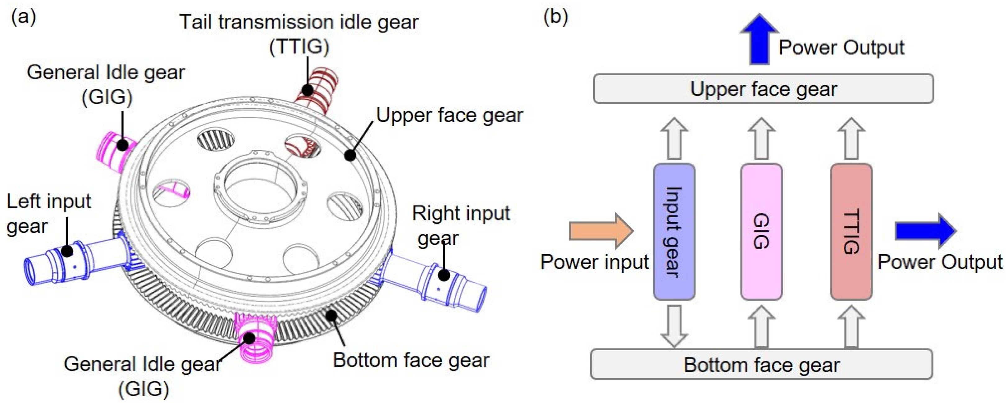
The structure of the FGST system is shown in Figure 1a. The system consists of seven gears, including upper and lower face gears, left and right input gears, left and right idler gears, and the tail gear. Generally, under the condition of conventional dual engine input power, the left and right input gears are the input of power for the FGST system, transmitting power from the input gear to the upper and lower face gears, which act as receivers of power, and rotate in opposite directions. The upper gear and tail gear are the outputs of the FGST system. As shown in Figure 1b, the upper face gear outputs power to the top rotor, while the tail gear outputs power to the tail rotor as needed. The left and right idler gears and the lower face gear play a role in improving the overall stiffness of the FGST.
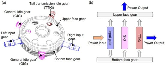
Figure 1.
The FGST system: (a) system structure, (b) diagram of power flow.
2.2. The Proposed Analysis and Optimization Integration Method Framework
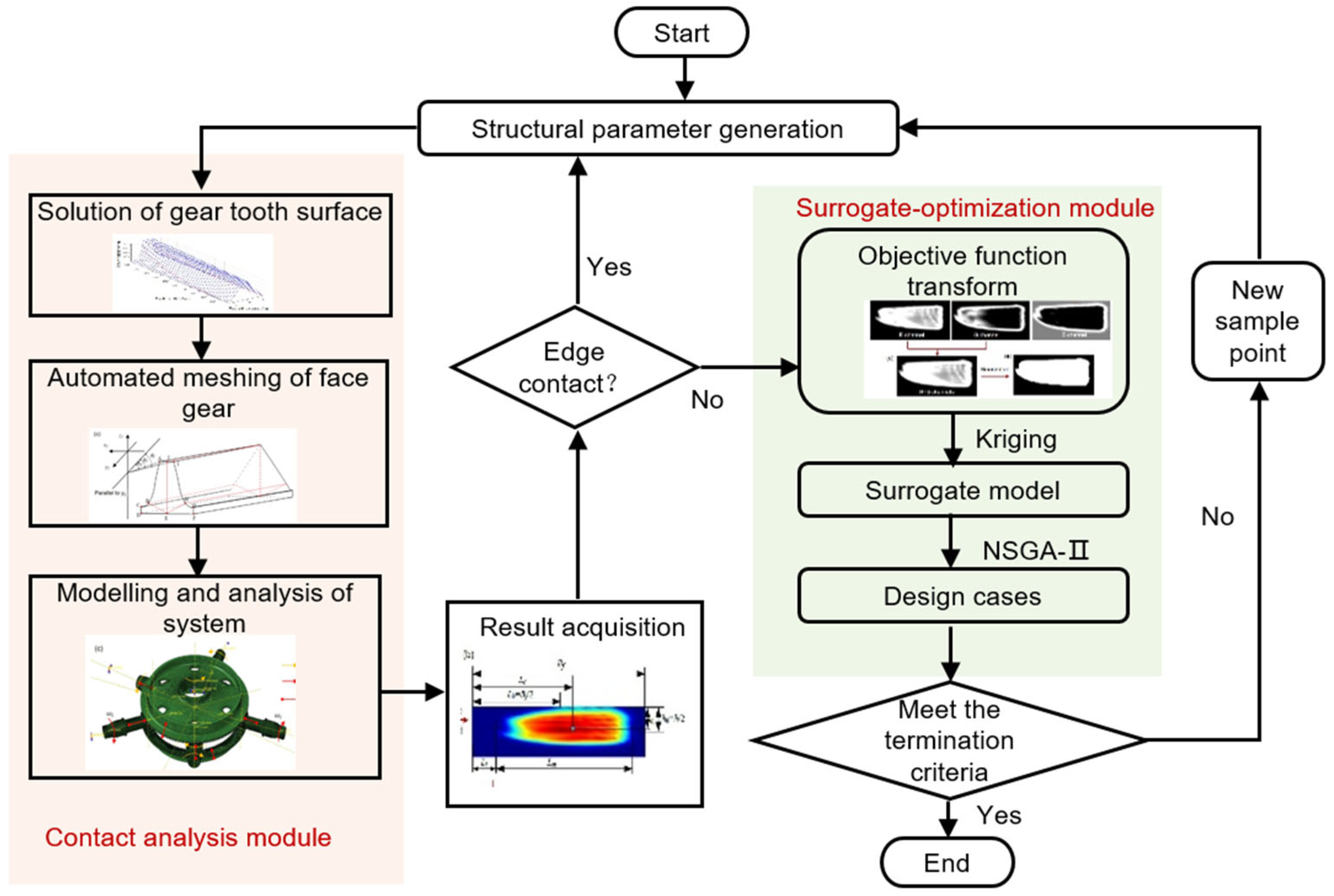
The FGST system consists of multiple transmission pairs, involving many parts and a complex transmission process. It is difficult to calculate its meshing trajectory using numerical calculation methods, and the influence of each gear and its corresponding modification parameters on the system’s meshing performance is not clear. Therefore, multiple sets of contact simulation models are established. Based on the contact simulation models, an integrated analysis optimization method for the FGST is proposed. This technology can automatically generate and optimize modification parameters considering the non-edge contact constraint to obtain the optimal parameter set.
The overall analysis and optimization integration design procedure, considering non-edge contact constraints, is described step by step as follows:
Step 1: Set the initialization modification parameters for the upper and lower gears and input gears, and solve the tooth surface equation.
Step 2: Automatically partition the mesh of the face gears and pinion.
Step 3: Finite element modeling and analysis of the FGST system.
Step 4: Acquire the contact results and calculate the contact stress at the edge of the tooth surface.
Step 5: If there is edge contact stress on the tooth surface, return to Step 1 to regenerate the modification parameters; otherwise, continue.
Step 6: Extract contact imprint location indicators and maximum contact stress indicators based on the contact stress image, and calculate the objective function.
Step 7: Establish a Kriging surrogate model, use NSGA-II to optimize the design variables, calculate whether the optimization termination conditions are met, and if so, obtain the optimal design parameters. Otherwise, return to Step 1.
The flowchart of the analysis and optimization integration process is shown in Figure 2. The detailed method in each step is described in the following section.
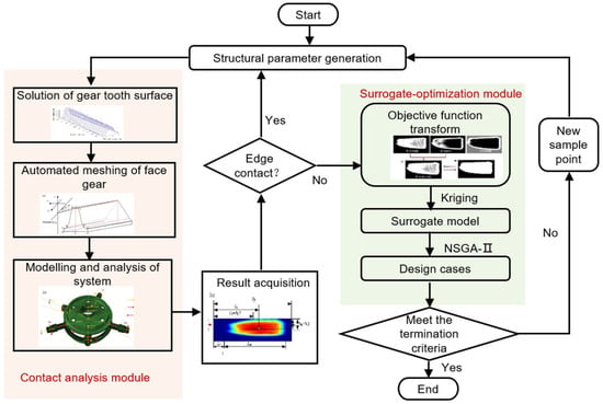
Figure 2.
The proposed analysis and optimization integration algorithm framework for the FGST system.
3. The Parameterized Mapping Method of the FGST System
3.1. Comprehensive Modification of Face Gears
The face gear, as the critical component, directly affects the contact performance of the FGST. Firstly, the model of the face gear and the entire system is established. Previous research has shown that unmodified non-orthogonal helical gear transmissions are prone to poor transmission phenomena such as edge contact, tooth separation, and angular contact. In our previous research, the tooth surface of the face gear adopts the triangle modifying method for the tooth crest, which has a significant improvement in contact characteristics.
3.1.1. Modification Parameters of Tooth Surface for Upper and Lower Face Gears
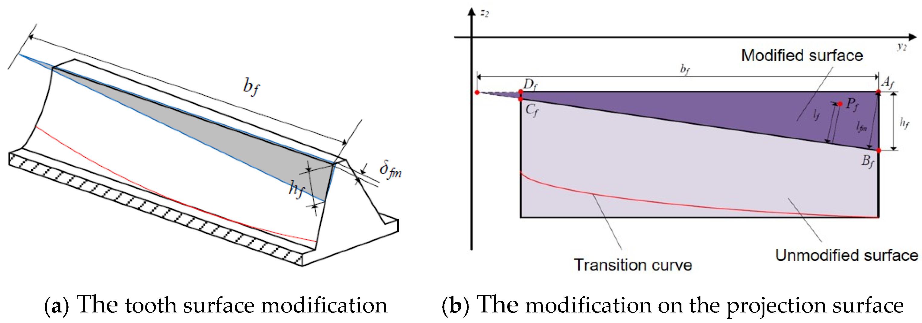
At the top of the outer radius teeth of the upper and lower face gears, which is the area where the face gear pair meshes, the tooth surface of the face gear is modified, as shown in Figure 3a. δfm is the maximum modification of the outer diameter, bf is the modification in the tooth width direction, which may be greater than the tooth width of the face gear, and hf is the modification in the tooth height direction. The projection of the gear tooth surface rotating to the y2o2z2 plane is shown in Figure 3b, where lfm is the distance from the outer diameter in tooth crest to the modification starting line, and lf is the distance from a point Pf in the modification area on the rotating projection surface to the modification starting line BfCf.
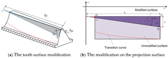
Figure 3.
Modification parameters for upper and lower face gears.
Coordinates of points on the tooth surface after modification
where x2, y2, and z2 are the point coordinates of the tooth surface in the unmodified face gear, while x2m, y2m, and z2m are the point coordinates of the tooth surface in the modified face gear. When x2 is positive, the sign in the equation is negative. When x2 is negative, the sign in the equation is positive. The function of is related to the design parameters; it is .
3.1.2. Modification Parameters of Tooth Surface for Pinion
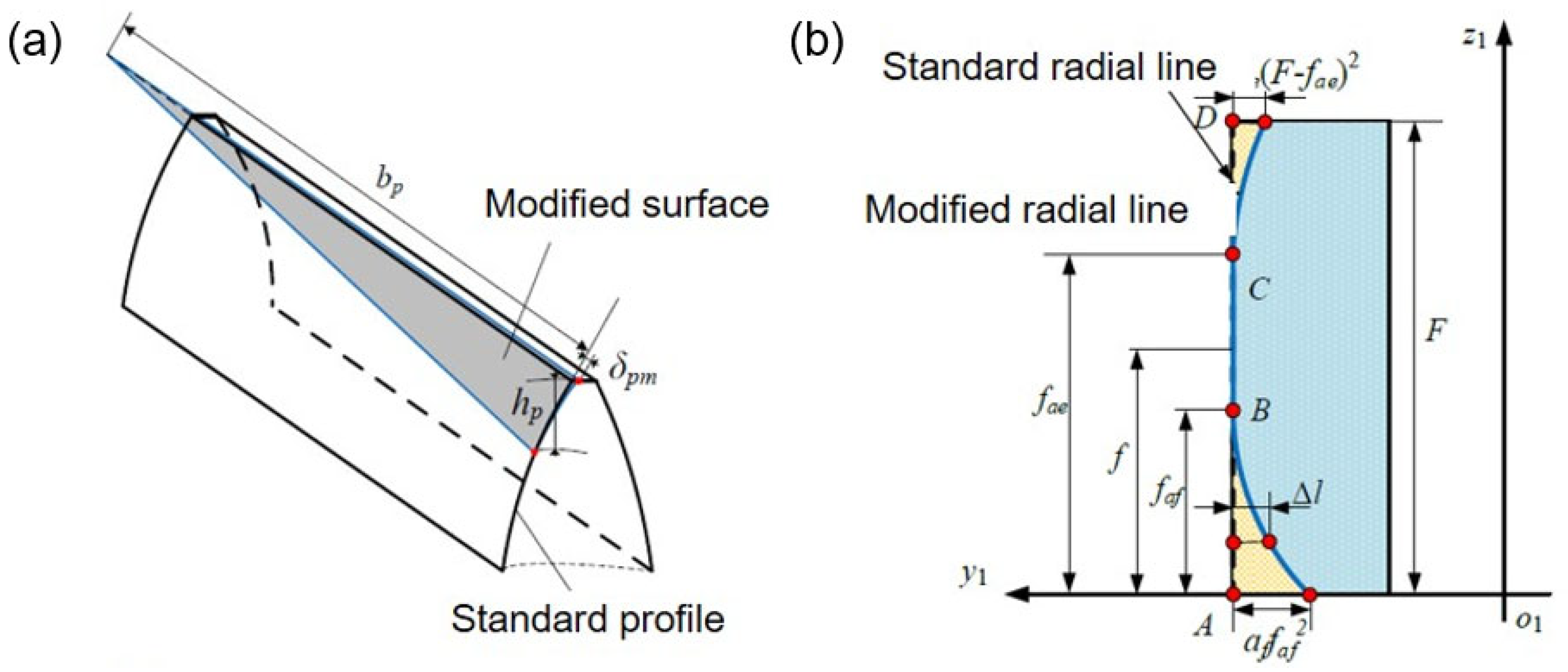
As shown in Figure 4, the tooth surface for the pinion (including input gears, idler gears, and tail gear in the split-torque transmission system) after tooth crest modification and tooth profile modification is:
where x1dj, y1dj, and z1dj are the point coordinates of the tooth surface in the pinion after tooth crest modification, which are the expressions for the modification parameters . is the expression for the tooth profile modification parameters, that is, .
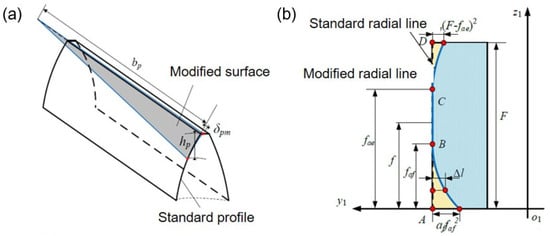
Figure 4.
The modification parameters for pinion: (a) schematic diagram of tooth crest modification, (b) tooth profile modification parameters.
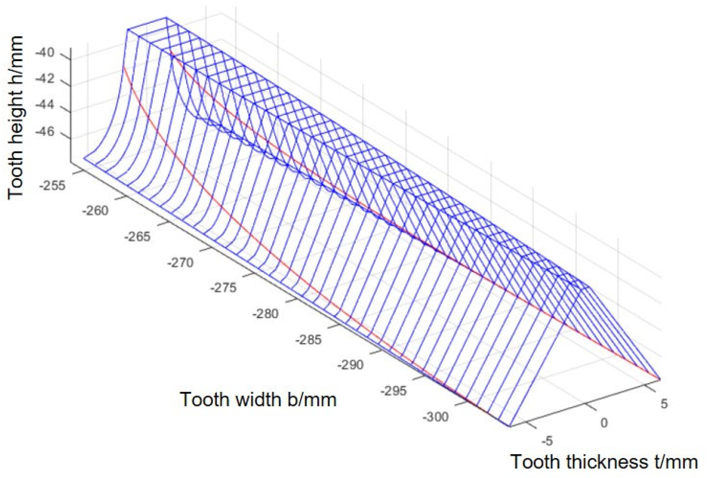
After modeling based on the modification parameters, the three-dimensional coordinates of the tooth surface points of the face gear are calculated, and the tooth surface is drawn as shown in Figure 5.
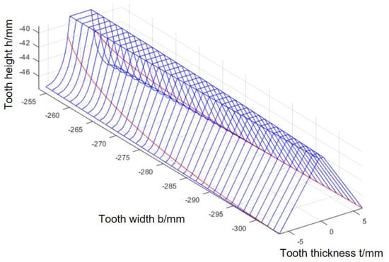
Figure 5.
Solution of the tooth surface.
3.2. Mapping Method for the Tooth Surface Modification Parameters to Mesh for Face Gears and Pinion
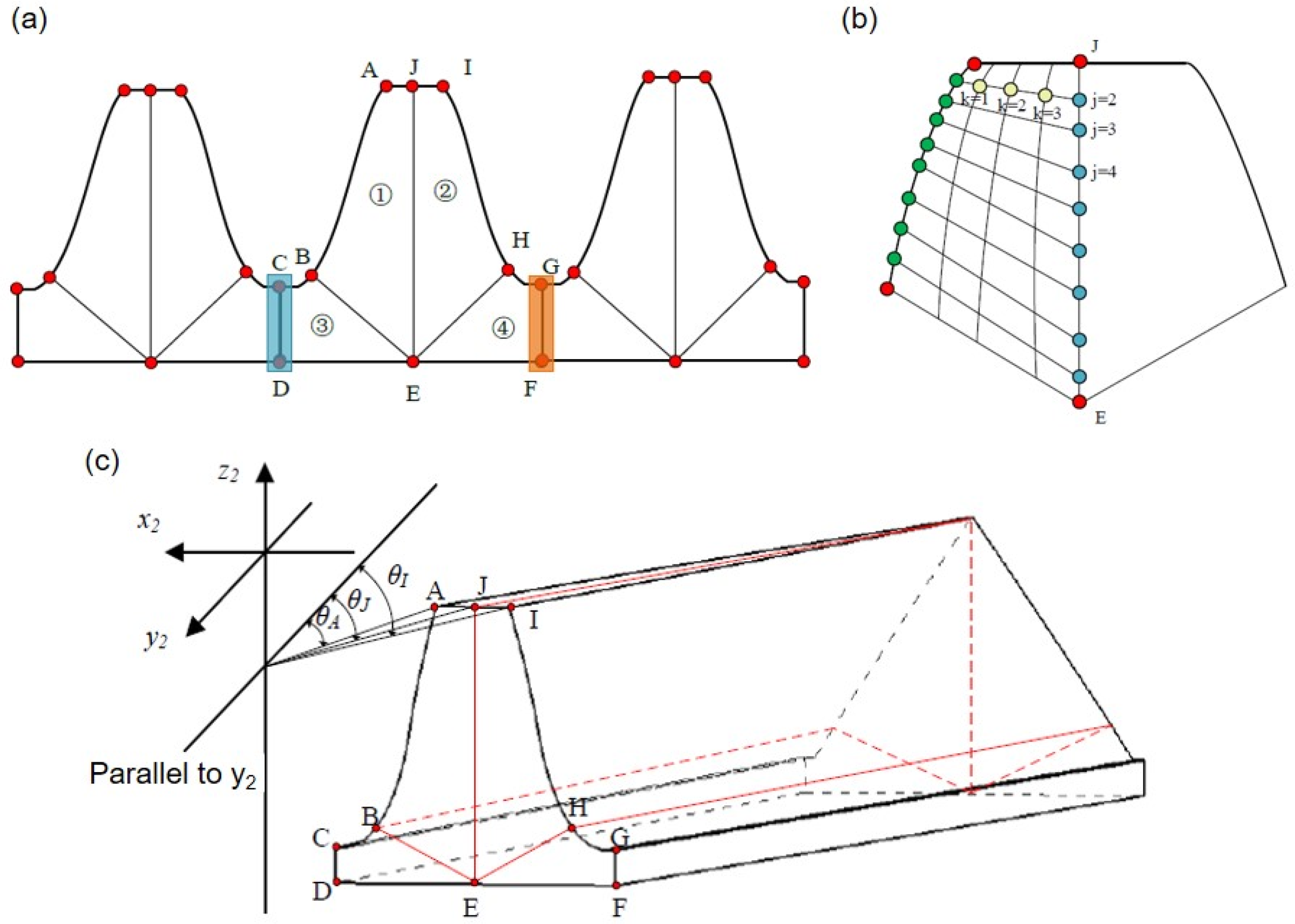
In the face gear split torque transmission system, the individual teeth of the face gear and the pinion are divided into four regions when partitioning the mesh. The schematic diagram of the block division of the end face of the face gear is shown in Figure 6. For the tooth surface area (areas I and II), a relatively dense mesh is often assigned, while a relatively sparse mesh can be adopted in the tooth root area (areas III and IV).
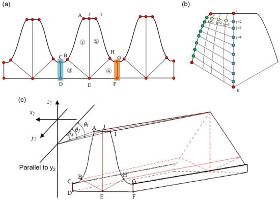
Figure 6.
Calculation of nodes in the face tooth. (a) Partition of multiple teeth; (b) calculation principle diagram of nodes on the tooth surface; (c) schematic diagram of the spatial relationship between key points.
The solution of nodes mainly consists of two steps, namely the calculation of key points and the calculation of other nodes. Key points include tooth crest points (points A, J, I), tooth surface points (points B, H, whose three-dimensional coordinate data is obtained by the tooth surface calculation program), tooth root points (points C, G, which are the midpoints of each tooth groove), tooth blank points (points D, F), and tooth center points (points J, E, which are determined by the coordinates of points on the left and right tooth surface). Based on the key points, sample the tooth surface and tooth root (see Section 2.1 for specific calculation steps of tooth surface points), and then perform interpolation calculation to obtain the coordinates of the remaining nodes.
To improve the applicability of the method, considering the case of helical gears, the key points A and I at the tooth crest may not be symmetrical about the y2-axis, and the key point J in the middle of the tooth crest may not be on the y2-axis. Its three-dimensional coordinates need to be further calculated. Considering that the face gear is formed around the z2 axis, the key points A, I, and J on the tooth crest should be on the same circle. The radius of this circle can be calculated as
The angle θA between point A and the y2 axis is
where xA and yA are points on the tooth surface of the face gear, which can be calculated in Section 2.1.
Similarly, the angle θI between point I and the y2 axis is
Then the angle θJ between the key point J on the tooth crest centerline and the y2-axis can be calculated as
Given the distance L1 from point H to the z2 axis, the coordinates of point H can be obtained as
The calculation method for the coordinates of other nodes is also similar to that of point J. The coordinates can be obtained by deriving the radius of the circle in which the point is located and the angle with the y2-axis. Calculation of the remaining nodes is similar to that of the key points. Take the calculation of nodes on the inner diameter as an example, as shown in Figure 6b.
Firstly, the coordinates of each point on the centerline JE are calculated. Given the number of seeds on the tooth surface, when the value of j ranges from 1 to + 1, the projection of the distance in the z2 direction between the corresponding points on the centerline (the blue points in the figure, with the first and last points as key points already calculated) is
The three-dimensional coordinates of each point on the centerline JE are
where the angle between each point and the y2-axis is θJ = θE. For the orthogonal face gear, the distance from the inner end face to the z2 axis is L1, which can be calculated using Equation (3).
Next, interpolation is used to calculate the coordinates of each node on the tooth surface. Taking j = 2 as an example, the nodes on the tooth surface (yellow nodes in the figure) are calculated. For the same j (corresponding to a half tooth mesh horizontal line), when the value of k ranges from one to the half tooth top seed number , the angle difference between the nodes on the horizontal line is
where θj,face is the angle between the node on the tooth surface and the y2-axis
The angle between each node and the y2-axis is
The projection of the distance between each node in the z2 direction is
The three-dimensional coordinates of each node on the horizontal line of the tooth surface are
where zj,face are the z-coordinates of the node on the tooth surface of row j.
The calculation of the remaining nodes on the inner radius face is similar to that of the tooth surface. First, calculate the coordinates of each point on the dividing line, and then use an interpolation algorithm to complete the calculation of the intermediate nodes.
The calculation method for key points and interpolation points on other teeth in the width direction is similar to the above method. It should be noted that the distance from different tooth width sections to the z2-axis needs to be calculated according to the tooth width.
The three-dimensional coordinate of the nodes of the remaining teeth can be calculated by removing duplicate node from the nodes of a single tooth and then rotating them, as shown in Figure 6a. After removing the point (blue part in the figure) on the left side of the single tooth blank of the face gear, rotate it by the corresponding angle of the tooth to obtain the coordinates of all nodes in the multi-tooth model.
When generating the model of the entire ring gear, based on a multi-tooth model, the last tooth needs to remove the node data at the connection between the left and right tooth blanks (nodes on the CD and GF in Figure 6a), for its left side is the previous tooth and its right side is the first tooth.
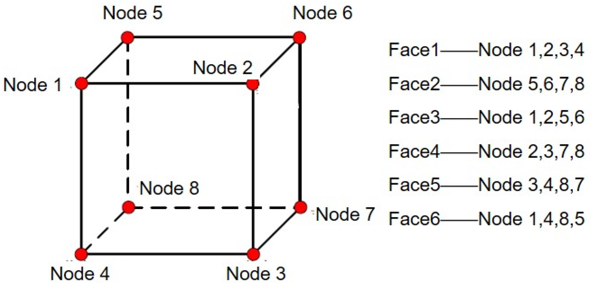
The three-dimensional coordinates of each node are written into the inp file, in the following format: node number, x coordinate, y coordinate, z coordinate. The node coordinates are written in the order shown in Figure 7. The numbering of each face of a hexahedral element in ABAQUS is specific, and the face numbering is determined by the four nodes connected to it, as shown in Figure 7. Node i (i = 1–6) is the ith input node when creating the elements. According to the right-hand rule, a circle is formed in the order of nodes 1, 2, 3, and 4, with the thumb pointing towards the inside of the elements.
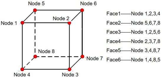
Figure 7.
Nodes and their corresponding face numbers.
3.3. Modeling of Split Torque Transmission System
After importing the inp file generated in the previous step into the frame file Frame, Python 3.9 programming is used to establish the simulation model. By calling the libraries and commands in ABAQUS 2020, development of ABAQUS 2020 is carried out to complete assembly, material, interaction, and other settings. The odb model database object records the ABAQUS 2020 finite element analysis model and specific analysis settings, mainly including the Model object group and the Job object group. The Model object stores information about the mesh and assembly relationships of various components, sets relevant properties of component materials, clarifies boundary conditions, sets simulation loads according to requirements, and can configure the computer resources occupied by the simulation.
4. A Fast Optimization Model Based on Kriging
4.1. Optimization Model of Tooth Surface Contact Performance
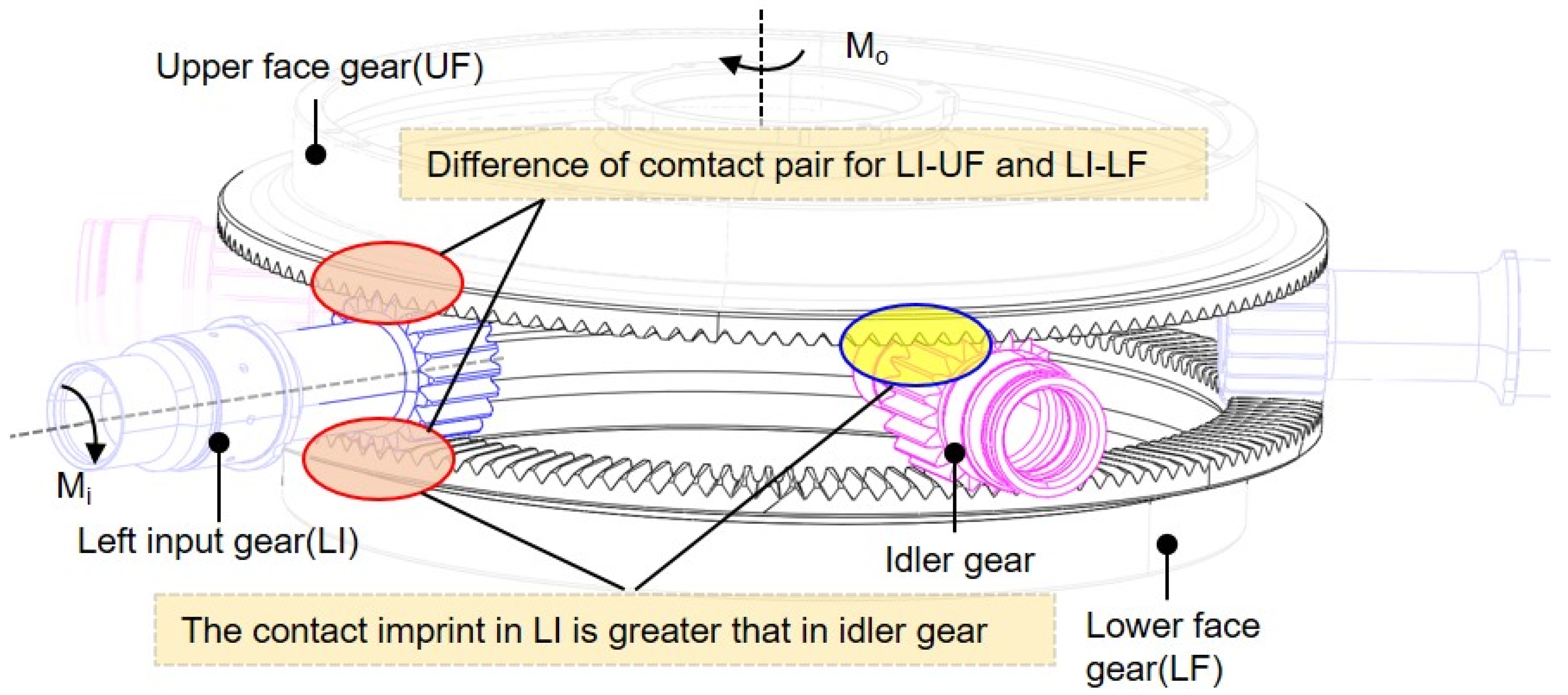
Due to the complexity of power transmission in the face gear split torque transmission system, the upper face gear plays a role in power output, while the lower face gear plays a role in power transmission, and the idler gear only plays a role in power transmission. Therefore, if all face gears and all pinions adopt the same modification scheme, there will be problems such as suboptimal tooth surface imprint positions and a relatively small proportion of idler gear imprint. As shown in Figure 8, to address this issue, a differentiated modification method for upper and lower face gears is used.
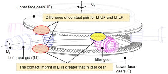
Figure 8.
Tooth surface contact for the split torque transmission system.
4.1.1. Image-Based Method of Contact Performance Index
The contact area is one of the important indicators for evaluating the meshing performance of gear transmission, and its position, shape, and size have an impact on the performance of gear transmission. To optimize the contact performance of the face gear split transmission system, this paper proposes an image-based method to obtain objective functions from contact area. The system should avoid edge contact, such as contact between the tooth crests, roots, and edges on both sides of the tooth width, which causes significant contact stress and reduces the service life of the gear. Generally, the larger the contact area, the lower the tooth surface stress. To make the position of the cylindrical gear (input gear) subjected to the force of the upper and lower face gears as consistent as possible, an optimized objective function is established with the contact area located at the center of the tooth surface to avoid edge contact.
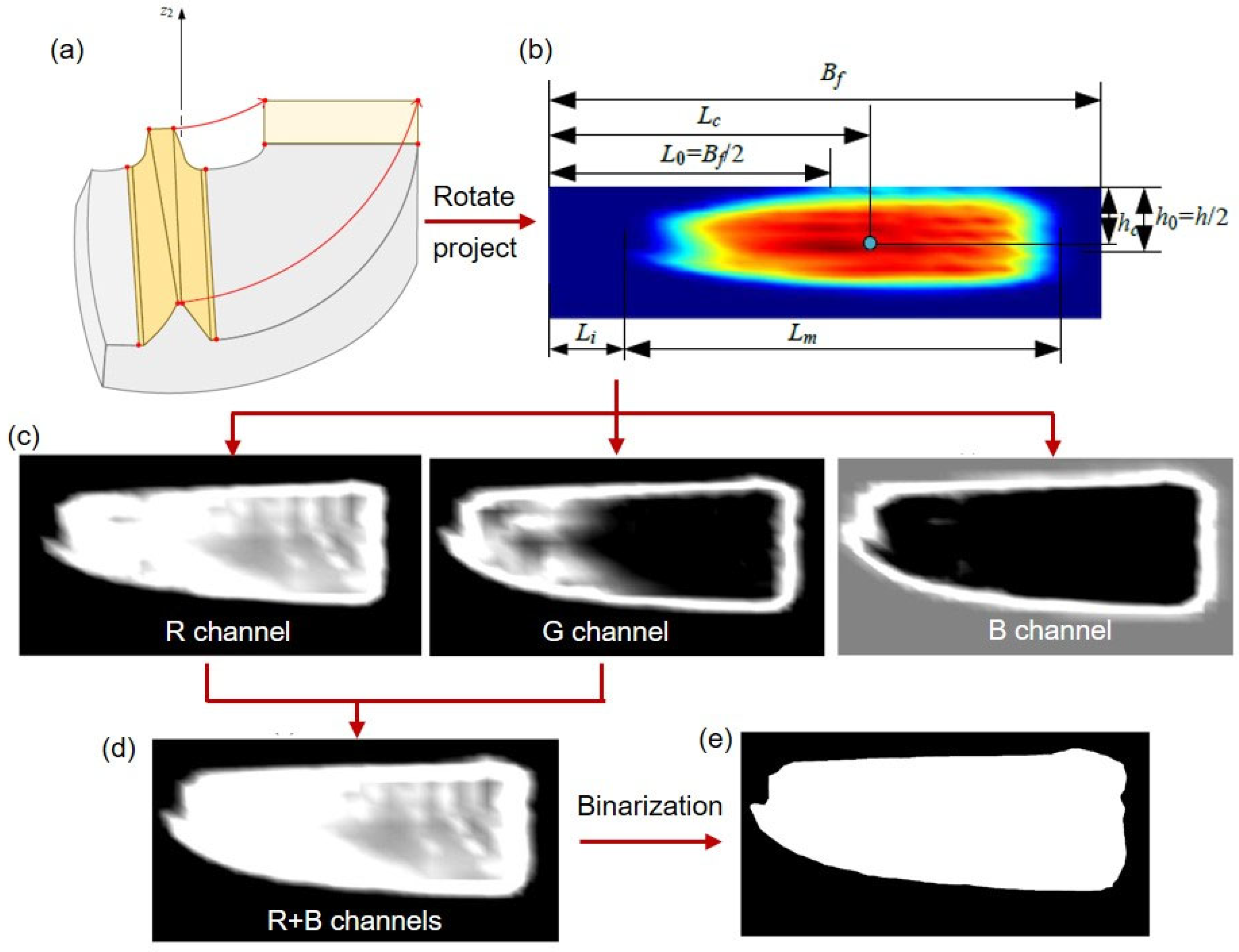
The objective function is established by projecting and rotating the gear tooth surface onto the yoz plane, as shown in Figure 9.
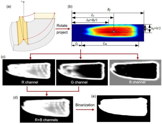
Figure 9.
(a–e) Establishment of the objective function.
Considering that the contact marks on the upper and lower face gear tooth surfaces should be located in the middle of the tooth surface in both the tooth height and width directions, the minimum contact stress on the tooth surface is required. The objective functions for optimizing the contact area can be expressed as Equation (15):
where hc and Lc are the positions on the projection surface where the center of the contact mark of the face gears is located, away from the tooth top and inner diameter. The superscripts u and b represent the upper and lower face gear, respectively. h0 is the midpoint of the meshing height (usually twice the modulus) in the tooth height direction, and L0 is the midpoint of the tooth width direction.
From the expression of OF1, the contact difference of the upper and lower face gears is considered. The position of the center of the contact area can be calculated based on the boundary and size of the contact area, is shown in Figure 9b.
To obtain the position of the imprint boundary, the stress is converted into a high-resolution image, and the values of the RGB channels for each pixel point are extracted and turned into grayscale images, as shown in Figure 9c. The center of the contact area on the red channel has the highest brightness, and the green channel tooth surface has a higher brightness than the edge area of the contact area, and is clearly compared to the non-contact area. The non-contact area on the blue channel tooth surface has a higher brightness and appears gray. Therefore, the tooth surface imprint of the face gear is reflected by overlaying the red and green channels, and the overlaid contact area is shown in Figure 9d. So the matrix
where the matrix R and G , representing the red channel and blue channel, respectively.
To further determine the boundary of the tooth contact imprint, the grayscale image was binarized, and pixels with brightness greater than were defined as white, and the other is defined as black, as shown in Figure 9e. Black represents the non-contact area, and white represents the contact imprint on the tooth surface.
where is the threshold. In our work, is set to 80.
By searching for the position of the first white pixel in the column from left to right, the position of the left boundary of the tooth contact imprint can be obtained. The left-bound boundary Li and Lm in Equation (16) is obtained by:
where colindex represents the column index, and l0 is the length of each pixel.
The center position of the contact area in the height direction hc is obtained by a similar method for calculating Lc. The index OF1 is obtained by Equation (15). The colindex is replaced by rowindex.
Another indicator OF2 is used to describe the uniformity of contact stress:
where CPRESSmax is the maximum contact stress on the gear tooth surface, while CPRESSmax0 is the maximum contact stress on the gear tooth surface of the original scheme, where all gears have not been modified.
Due to the multi-objective optimization, to facilitate the calculation of the objective function, a weighted method is adopted to establish the final optimization objective function, as shown in Equation (17). According to the actual engineering situation, the weight of the optimization objective is taken as ω1 = 0.4, ω2 = 0.6.
4.1.2. Optimization Variables
According to the diagonal modification method, the parameters of the face gear tooth surface include the maximum modification of tooth crest δfm, the modification length in the tooth width direction bf, and the modification height in the tooth height direction hf. The diagonal modification parameters δfm, bf, and hf affect the position and shape of the surface gear imprint, which should be adjusted to avoid edge contact at the tooth crest of the face gear.
The parameters of the pinion include the maximum tooth crest modification δpm, the modification length bp in the tooth width direction, the modification height hp in the tooth height direction, the starting position parameter faf for tooth direction modification, the maximum modification δpf for the front surface, the starting position parameter fae for tooth direction modification of the pinion rear end surface, and the maximum modification δpe for the rear end surface. The diagonal modification parameters δpm, bp, and hp affect the shape of the imprint on the top of the pinion teeth, which should be adjusted to avoid edge contact in the pinion tooth crest area (which is also the root area of the face gear teeth).
4.1.3. Constrained Condition
To avoid edge contact of the face gear pair, the following constraints should be met.
It indicates that the tooth surface contact stress at all points on the inner radius (L1), outer radius (L2), and tooth crest edge line (z0) of the gear tooth surface must not exceed zero, that is, no edge contact occurs. The front and rear end face modification areas of the input gear coincide; thus, the relationship between the starting points of the front and rear end face modification is constrained.
In addition to the above constraints, more importantly, we automatically extract FEA results before sampling to determine whether edge contact occurs on the tooth surface, as shown in Figure 2. If edge contact occurs, abandon the sample point and generate a new one for automatic calculation of the finite element until a point without edge contact is sampled as the effective optimized sample point.
4.2. An Improved Optimization Method
The optimization process is shown in Figure 1. The initial set of sample points is generated through the Design of Experiments (DoE) method. The analysis and optimization integration technology are used to perform system contact simulation analysis on the generated multiple modification schemes (input variables), establishing the initial Kriging surrogate model. According to the expected improvement criterion (EGO method), the genetic algorithm (NSGA-II) is used to iteratively solve the sub-optimization problem and obtain new sample points (modification scheme). Based on the new sample points, system contact simulation analysis and calculation are carried out to obtain the corresponding response values (objective function, i.e., imprint position) and approximate values. The Kriging model is trained on the new dataset. If the response value of the new sample point meets the iteration termination condition, output the current sample point and response value; otherwise, continue the iteration loop.
4.2.1. Kriging Model
The first step of the surrogate model is to adopt the design space. To obtain a more uniform sample of points in the design space, it is necessary to use the Design of Experiments (DoE) method to select appropriate sample points. This study used Optimal Latin Hypercube sampling (OLHS) to generate sample points, and the LSH sampling method can achieve high sampling accuracy with smaller sample sizes, improving the uniformity of sample point distribution. The Kriging model is briefly introduced as follows:
where represents the predicted result, and is the regression function vector. is the Gaussian distribution random process with zero mean and a variance of . The covariance
where and is the variable in the design space. is a correlation function, where a square exponential correlation function is adopted and expressed as
where is the undetermined parameter in the model.
is the correlation coefficient vector, which can be evaluated by
where , , and is sampling number.
4.2.2. Adding Points Criteria
Adopting the Improved Expectation Criterion (EGO) as a point adding criterion to continuously optimize the surrogate model, its expression is
where I(x) is the improvement of the predicted value of the Kriging model relative to the current optimal response value, ymin is the minimum value of the current objective, is the predicted value, is the cumulative distribution function of the standard normal distribution, and is the probability density function of the standard normal distribution. s is the prediction standard deviation of the Kriging model, and the expression for the improvement is
Equation (29) indicates that the larger the predicted value Y(x) and the smaller the predicted standard deviation s, the larger the first term of the EI value, indicating that the EI is used to find points where the predicted value is larger than the current optimal value and the prediction is more accurate. The larger the prediction standard deviation s, the larger the second term of EI, indicating that the EI criterion tends to add new sample points in areas where Kriging prediction values are optimal and prediction uncertainty is high. Therefore, the EI criterion has the ability to search locally and develop globally optimal regions.
4.2.3. Optimization Termination Conditions
Optimizing termination conditions are essential in optimizing a model. If any of the following three termination conditions are met, the loop ends:
- (1)
- The difference between the newly added sample points and the response values, i.e.,
- (2)
- The difference between the objective function value of the newly added sample points and the predicted value of the surrogate model, i.e.,
- (3)
- The number of iterations is greater than the maximum number of iterations.
5. Case Study
5.1. Contact Performance Analysis of the FGST System
5.1.1. Accurate 3D Geometric Modeling
This paper takes a split torque transmission system of a certain face gear as an example to establish a model. As a complex surface, the tooth surface of the gear cannot be directly modeled by simple modeling commands such as stretching, and accurate three-dimensional coordinates of the tooth surface points need to be calculated for fitting. The basic parameters of the face gear are shown in Table 1.

Table 1.
Basic parameters of the upper and lower face gears in split torque transmission system.
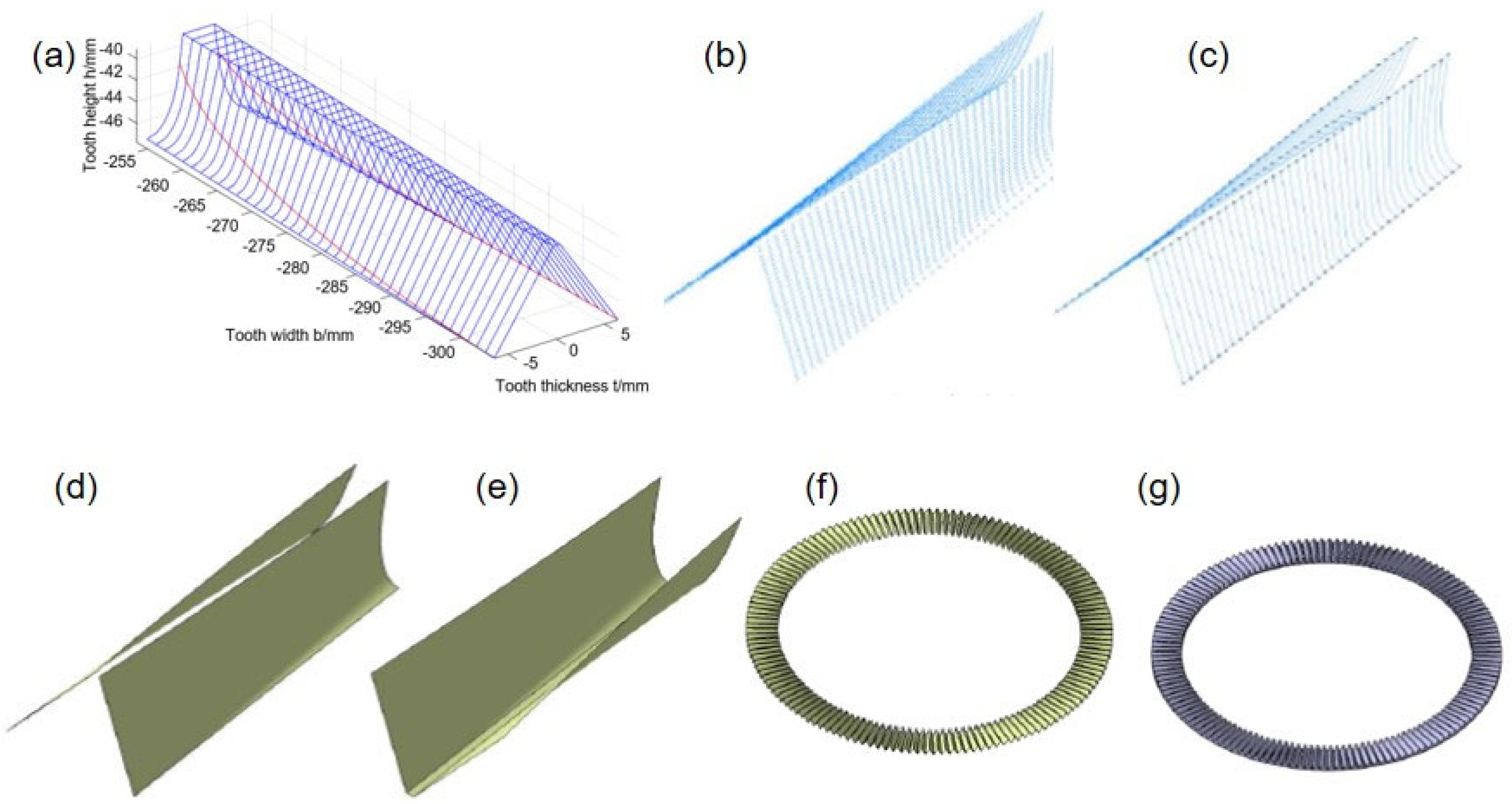
According to the tooth surface equation of the face gear, calculate and solve the three-dimensional coordinates of the tooth surface points of the face gear by MATLAB R2021b, as shown in Figure 5. After obtaining the numerical tooth surface of the face gear, the discrete points of the face gear tooth surface are imported into the 3D modeling software. The points are fitted to spline curves in the order of tooth height, and finally are fitted to the surface, as shown in Figure 10. The basic design parameters of a cylindrical gear are shown in Table 2, and the modeling process is similar to that of a face gear.
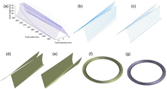
Figure 10.
The geometric modeling process of face gears: (a) solution of tooth surface equation; (b) discretization of tooth surface equation; (c) fit points to lines; (d) fit lines to surfaces; (e) construction of tooth groove surface; (f) array of tooth slot surfaces; (g) tooth surface segmentation.

Table 2.
Parameters of the pinion in the split torsion transmission system.
5.1.2. Finite Element Modeling and Analysis
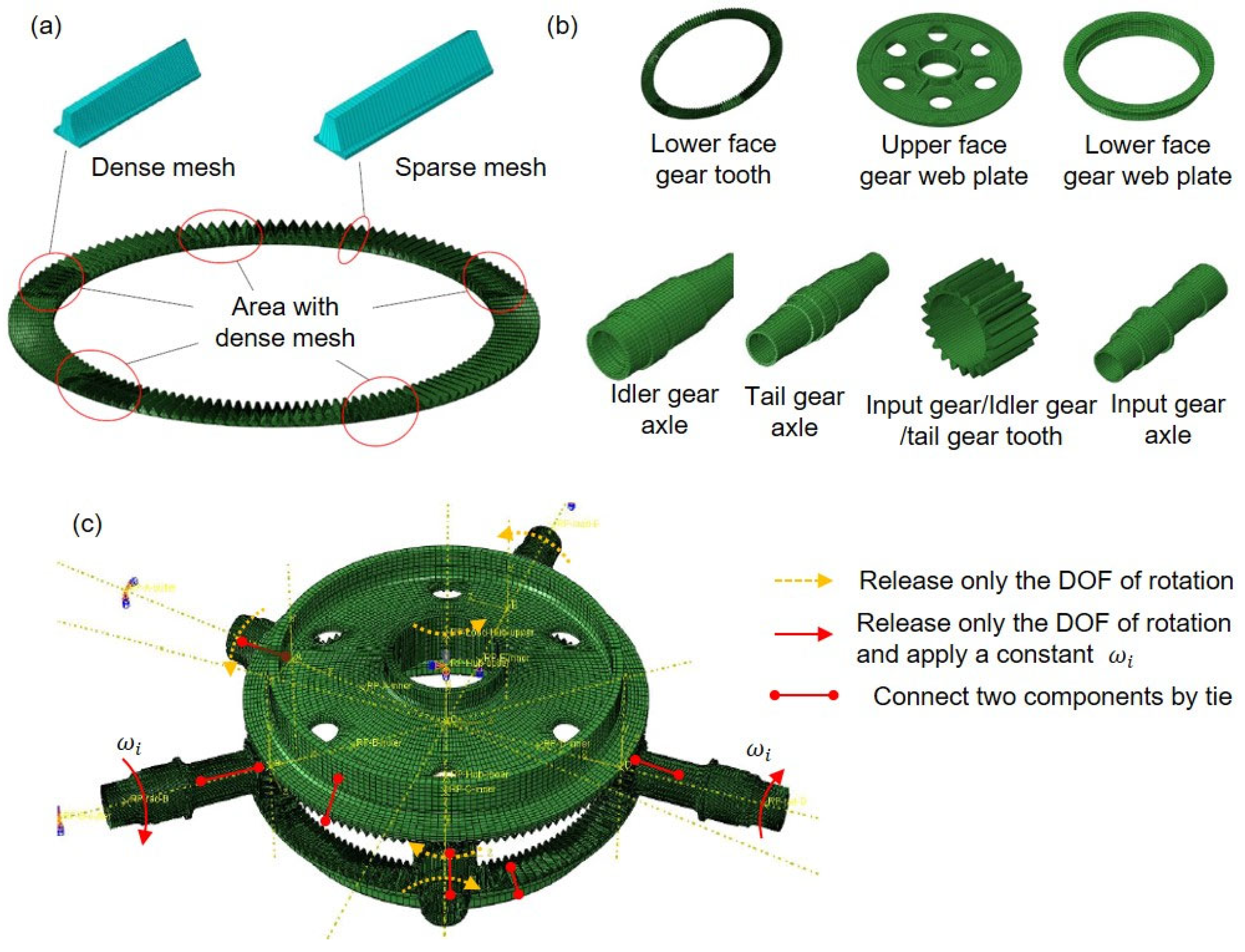
Hexahedral meshes are used to partition the components of the FGST system. The mesh division of the upper face gear teeth is shown in Figure 11a. When generating the mesh of the entire face gear teeth, different mesh densities are set according to the assembly relationship. A dense single tooth mesh is set in the meshing area to improve the accuracy, while a sparse single tooth mesh is set in the non-meshing area to accelerate the calculation. The number of seeds on the tooth surface of a dense single tooth is 15, and the total number of elements on a single tooth is 4800. The number of seeds on the tooth surface of a single tooth with sparse mesh is 1, and the total number of elements on a single tooth is 1440. The total number of gear teeth mesh on the merged upper face gear is 338,880.
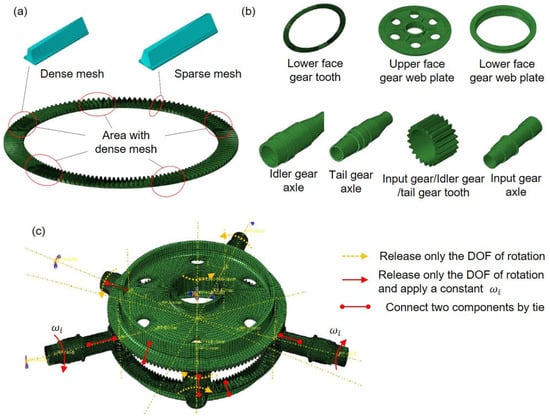
Figure 11.
FEM of the split torsion transmission system. (a) Mesh of upper face gear tooth, and (b) other components; (c) loading condition and constraint of these components.
The entire system is divided into 10 components, including input gear teeth and input gear axles, and is meshed as shown in Figure 11b.
The interaction between “contact and surface contact” is set according to the corresponding meshing relationship between each gear pair and gear tooth, the upper face gear and the upper web plate, the lower face gear and the lower web plate, and the pinions (input gears, idler gears, and tail gear) and axles are all connected by Tie. In the analysis step of simulating meshing, boundary conditions are set to the input gear to limit its rotation angle, simulating the rotation of the input gear and driving the upper and lower face gears to move together. For the idler gear, input gears, tail gear, the upper and lower face gears, the degree of freedom around the axis rotation is released and the other degrees of freedom are constrained.
5.2. Contact Area Test and Its Verification
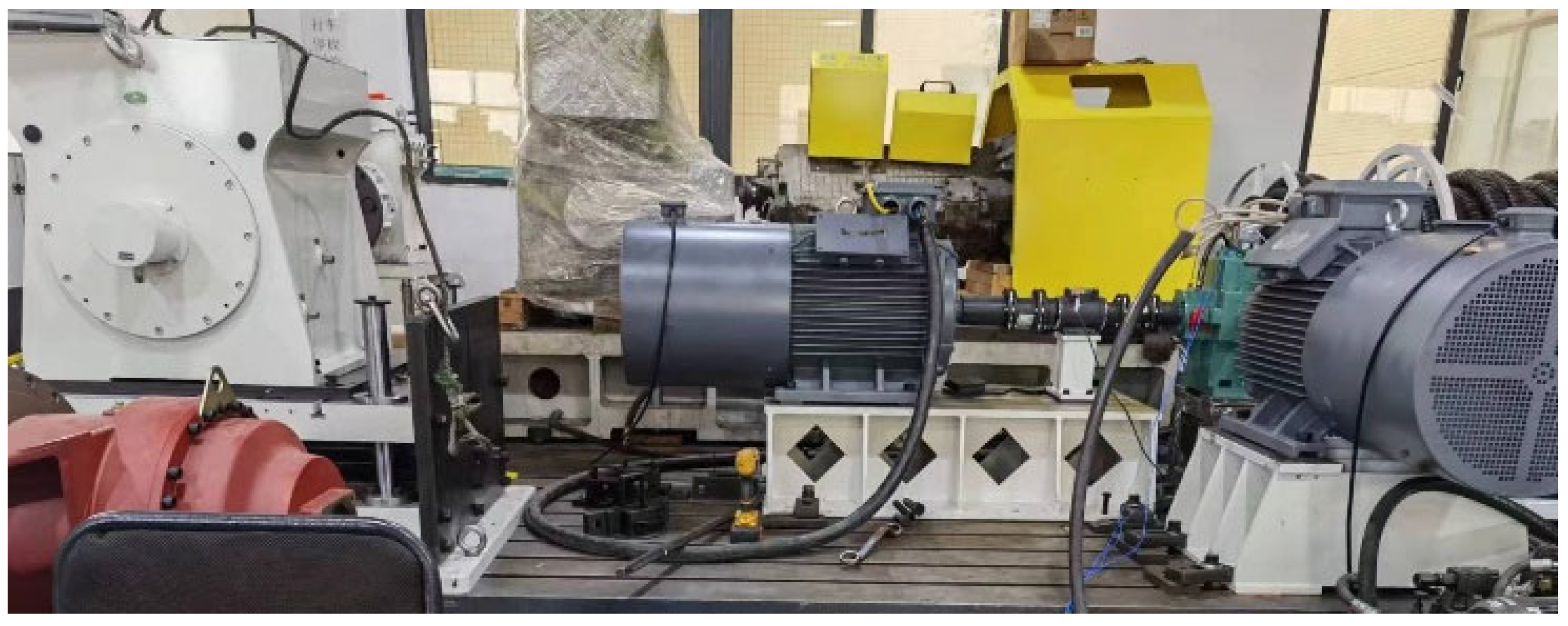
Before the loading test, the tooth surfaces of the face gear and cylindrical gear were cleaned and sprayed with white paint. This white paint is resistant to lubricating oil erosion and peels off under the contact action between the two tooth surfaces, thereby revealing the contact patterns. This study employs a specially designed test bench tailored for the face gear split torque transmission system, which integrates key components including a drive motor, torque sensors, and a loading system. In the loading contact experiment, the output power of the upper face gear is set to 3200 kW, with the input gear speed maintained at 7300 r/min. The torque of the upper face gear is calculated as 4186.3 nm using the formula T = 9550 × P/n, where P is power in kW and n is speed in r/min. For loading control, a hydraulic loader is utilized to apply stable loads to the transmission system. To avoid excessive shedding of the white paint on the tooth surfaces due to prolonged operation, the test run duration was set to 5 min. After the operation was completed, a high-precision camera was used to capture images of the tooth surface contact patterns, as shown in Figure 12.
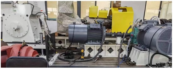
Figure 12.
The test bench.
Using the parametric mapping method proposed in this paper, on a workstation configured with an Intel(R) Xeon(R) Platinum 8272CL CPU @ 2.60 GHz and 192 GB of RAM, the time previously spent on manual operations during each analysis and modeling phase in traditional processes has been reduced from 4–5 h to less than 0.5 h. Meanwhile, the total duration of the optimization process has been reduced from 10–15 days with traditional methods to 1~3 days.
The parameters are shown in Table 3, where the modification parameters of the upper and lower gears are consistent, and the modification parameters of each cylindrical gear are consistent. The elastic modulus is 210 GPa and the Poisson’s ratio is 0.29.

Table 3.
Modification parameters of the split torque transmission system.
The coloring pigment is applied to the face gear using the coloring method, all the gear are assembled correctly, and the assembly position is adjusted to ensure that the tooth surfaces of each gear are meshed correctly. The experimental platform is turned on, and then the speed of the input gear is increased. Meanwhile, the upper face gear is gradually loaded to the working condition. After running for a period of time, the experimental platform is stopped to open the outer casing. The gears are removed to take out the experimental imprint and measure the width and the center of the imprint.
Due to the simultaneous meshing of the upper face gear with all input and idler gears, however, during the simulation calculation of contact imprints, only a few teeth were engaged between the pinion at each position and the upper face gear. Therefore, to compare with the experiment, when extracting the simulation results, the contact imprint cloud maps of the upper face gear and the pinions at each position are stacked to obtain the final contact simulation results of the gears. The same method is applied to the input gears. The simulation and experiment of the contact area between the upper face gear and the input gear are shown in Figure 13. The modeling time for manual operation is reduced to less than 0.5 h, greatly improving the efficiency of modeling analysis.

Figure 13.
Comparison of contact areas in simulation and tests.
Simulation and experimental results show that the contact area between the input gear and the upper face gear occupies most of the tooth surface, and the center of the imprint on the upper face gear tooth surface is more inclined towards the outer radius of the face gear compared to the input gear. Meanwhile, the following conclusions can be drawn:
- (1)
- The simulation results of the upper face gear show that the ratio of the length of the tooth contact imprint in the tooth width direction to the entire tooth width of the face gear is 0.839. The value obtained by test is 0.817. The deviation between the simulation and the experimental results is 2.69%.
- (2)
- The contact simulation results of the input gear show that the ratio of the length of the tooth surface contact imprint in the tooth width direction to the width of the entire tooth surface is 0.827. The value obtained by test is 0.875. The deviation between simulation and experimental results is 5.49%.
- (3)
- Comparing the simulation and experimental results of the upper face gear and input gear, the position, shape, and size of the tooth surface contact imprint are basically the same, and they have consistent imprint characteristics (such as the sharp corners of the imprint).
Therefore, the contact simulation model of the system has high accuracy, and further optimization can be carried out based on the established simulation.
5.3. Optimization Design and Result Analysis
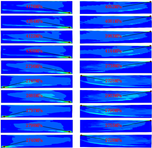
Before optimization, we calculated the case without any modification, and the contact patterns are listed in Table 4. It can be seen that severe stress concentration and edge contact occurred. The maximum stress on the tooth surface reaches 4144 MPa.

Table 4.
Contact pattern of non-modification case.
The optimization variables and their value ranges are shown in Table 5, with a total of 13 variables, which are set by considering the actual significance of each variable and the tooth crest circle and tooth thickness of the gears.

Table 5.
Optimization variables and range of values for the model.
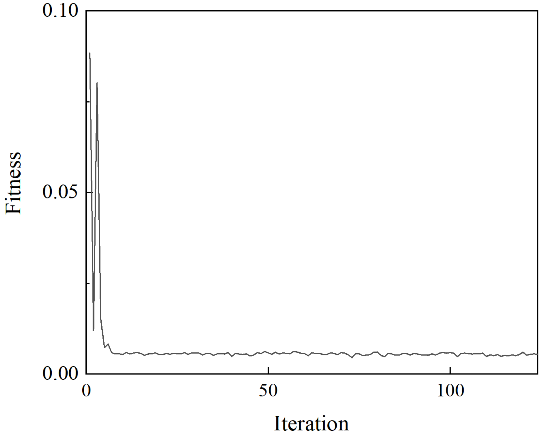
The fitness history of the optimization is shown in Figure 14. The number of samples used to construct the Kriging model is 36. The optimal design scheme obtained is shown in Table 6.
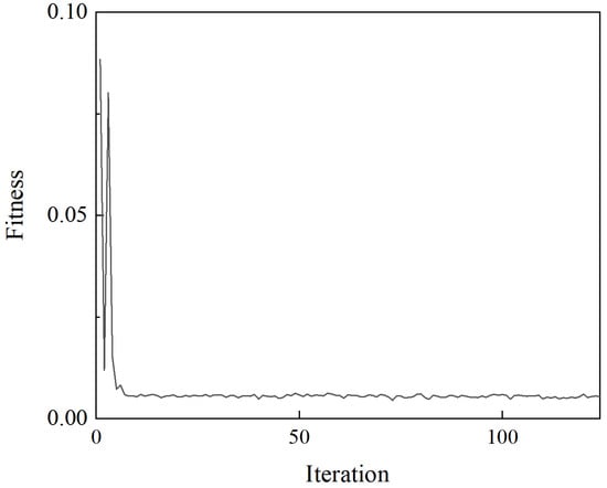
Figure 14.
Fitness history of the optimization.

Table 6.
Optimal design parameters.
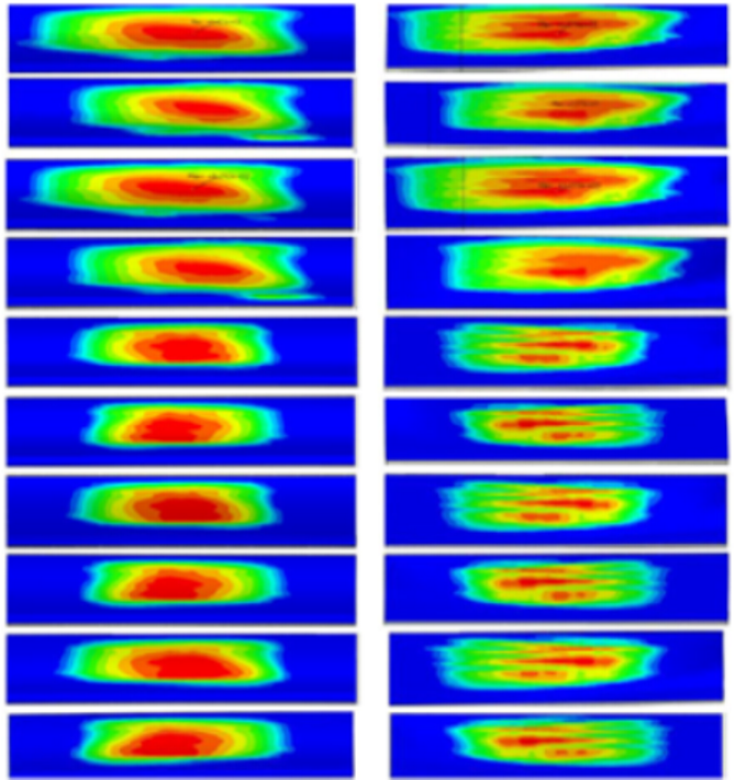
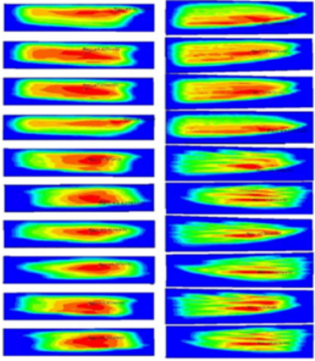
The simulation model of the system based on the optimal values is established and analyzed, and the modification parameters of the idler gears were iteratively optimized several times. The simulation results are shown in Table 7.

Table 7.
Contact comparison for optimal design.
For the contact between the input gear and the face gear, the contact between the left and right input gears, and the upper and lower face gears is relatively consistent, respectively. The contact area on the tooth surface of the face gear is relatively centered in both the tooth width and tooth height directions. Comparing the contact between the left and right input gears and the upper and lower face gears, it can be seen that the tooth surface imprint shapes of the face gears in the contact pair between the left input gear and the lower face gear, and the contact pair between the right input gear and the upper face gear are similar, while the tooth surface imprint shapes of the face gears in the contact pair between the left input gear and the upper face gear, and the contact pair between the right input gear and the lower face gear are relatively similar. For the contact between the idler gear and the face gear, the contact area on the tooth surface of the face gear is relatively large, and the contact area of the upper face gear is slightly larger than that of the lower face gear.
From the simulation, it can be seen that the schemes with good system meshing performance are obtained using the Kriging surrogate model. To further quantify the effect of its performance improvement, Table 8 presents the maximum contact stress and the deviation of the center position of the contact pattern from the midpoint of the tooth width before and after optimization. This deviation can be calculated as

Table 8.
Comparison of the deviation of the center position of the contact pattern from the midpoint of the tooth width and the maximum contact stress on the tooth surface before and after optimization.
As can be seen from Table 8, compared with the state before optimization, the centers of tooth contact patterns for most meshing pairs after optimization are closer to the middle of the tooth width (i.e., smaller ΔD values). The distances between the contact pattern centers and the tooth width centers at the meshing positions of the two input pinions with the face gear were significantly reduced. For example, LI-UF decreased from 2.91 mm to 0.34 mm, a reduction of 88%; LI-BF decreased from 0.94 mm to 0.70 mm, a reduction of 26%; RI-UF decreased from 2.64 mm to 1.59 mm, a reduction of 40%; and RI-BF decreased from 1.44 mm to 0.61 mm, a reduction of 58%. The maximum reduction in ΔD at LIG-UF reached 92%, while reductions at RIG-UF and TG-UF were 87% and 22%, respectively. However, there are still three positions—LIG-BF, RIG-BF, and TG-BF—where the deviation distance increased. This is because the optimization process balanced the constraints of the contact pattern center position and tooth surface contact stress. After optimization, the width of the contact patterns at these three positions increased, and the maximum contact stress decreased, but the centering of the contact pattern centers was sacrificed. This is acceptable in practical engineering applications because no obvious edge contact occurred on the tooth surfaces at these three positions.
Regarding contact stress, due to the larger optimized tooth contact patterns, the maximum tooth surface contact stress at different meshing pairs was significantly reduced. For the meshing positions between idlers and the face gear (LIG-UF, LIG-BF, RIG-UF, RIG-BF, TG-UF, and TG-BF), since the contact pattern areas were smaller before optimization, the contact patterns increased more significantly after optimization, leading to a marked reduction in contact stress—almost all reductions exceeded 15.2%. For the remaining four input pinion meshing positions, since their tooth contact patterns were already relatively large before optimization, there was less room for increasing the contact pattern area. Thus, the reduction in contact stress was less significant than that at the idler positions, with the maximum contact stress reduction being 14.9% at LI-UF.
In summary, in the optimized scheme, both the deviation of the contact pattern center positions and the maximum tooth surface contact stress were significantly reduced, which verifies the effectiveness of the method proposed in this paper.
6. Conclusions
This paper proposes an analysis and optimization integration method considering the non-edge contact constraint to quickly optimize the modification parameters in the FGST system. This method improves modeling efficiency and system contact performance. The main conclusions are listed as follows:
- (1)
- A method for automatic modeling considering the modification parameters of face gears has been proposed to achieve the modeling and optimization for the FGST system. The time required for manual participation in modeling is shortened to less than 0.5 h, which greatly improved design efficiency.
- (2)
- An image-based method for quantifying the contact characteristics of face gears was proposed, and an objective function for optimizing the contact characteristics was established, achieving the optimization of the contact characteristics. The maximum tooth surface contact stress is reduced by 77.30%.
- (3)
- Considering the load differences of different power paths, the balanced design of different contact pairs (including input gears and upper and lower gears, face gears and idler gears) has been achieved, improving the overall contact performance of the system.
Author Contributions
Conceptualization, Y.Z. and B.L.; methodology, B.L.; software, W.T.; validation, Z.Y., Z.T. and B.L.; formal analysis, Z.Y.; investigation, Z.Y., X.H. and Z.W.; resources, Y.Z. and J.T.; data curation, X.H.; writing—original draft preparation, B.L.; writing—review and editing, Z.Y., B.L. and Z.W.; visualization, B.L. and X.H.; supervision, Y.Z.; project administration, Y.Z.; funding acquisition, Y.Z. and B.L. All authors have read and agreed to the published version of the manuscript.
Funding
This research was funded by the Industry University Research Cooperation Project of China Aviation Engine Group Co, Ltd., Grant number HFZL2024CXY020, National Key R&D Program of China, Grant number 2024YFB3410402, National Natural Science Foundation of China, Grant number 52075558, by Science and Technology Innovation Program of Hunan Province, Grant number 2021RC3012, by Central South University Innovation-Driven Research Program, Grant number 2023CXQD050, by the Fundamental Research Funds for the Central Universities of Central South University, Grant number CX20230255, by AECC, Grant Number KY-1044-2023-0461, and by the Project of State Key Laboratory of Precision Manufacturing for Extreme Service Performance, Grant Number ZZYJKT2025-07.
Institutional Review Board Statement
Not applicable.
Informed Consent Statement
Not applicable.
Data Availability Statement
The original contributions presented in this study are included in the article. Further inquiries can be directed to the corresponding author.
Conflicts of Interest
Author Zhen Yu was employed by the AECC Zhongchuan Transmission Machinery Co., Ltd. The remaining author declares that the research was conducted in the absence of any commercial or financial relationships that could be construed as a potential conflict of interest.
References
- Lin, Y.; Huang, Y.; Huang, T.; Yin, Z. Open-hole tensile behaviour and failure prediction of carbon fibre reinforced aluminium laminates. Polym. Compos. 2018, 39, 4123–4138. [Google Scholar] [CrossRef]
- Le, K.Q.; Wu, Y.R.; Luu, T.T. A Mathematical Modeling of Computer Numerical Control Skiving Process for Manufacturing Helical Face Gears Using Sensitivity Matrix Combined with Levenberg–Marquardt Algorithm. J. Manuf. Sci. Eng. 2024, 146, 091007. [Google Scholar] [CrossRef]
- Jiang, C.; Shang, Y.; Wang, Z.; Han, Z.; Deng, J. Optimal calculation and experimental study on cutting force of low-angle straight tooth face gear by power skiving. Int. J. Adv. Manuf. Technol. 2024, 135, 3961–3982. [Google Scholar] [CrossRef]
- Han, Z.; Jiang, C.; Deng, X.; Zhang, C.; Geng, L.; Feng, Y. The Grinding and Correction of Face Gears Based on an Internal Gear Grinding Machine. Machines 2024, 12, 496. [Google Scholar] [CrossRef]
- Sheng, W.; Li, Z.; Yu, X. Research on the top cutting features on face gears using normal to tooth profile method. Eng. Sci. Technol. Int. J. 2024, 59, 101849. [Google Scholar] [CrossRef]
- Huang, K.; Yu, J.; Luo, H.; Shang, Z.; Huang, S.; Fu, L. An efficient vectorization solution to cutting dynamics modeling for face-hobbing of hypoid gears. Mech. Mach. Theory 2024, 191, 105504. [Google Scholar] [CrossRef]
- Zanzi, C.; Pedrero, J.I. Application of modified geometry of face gear drive. Comput. Methods Appl. Mech. Eng. 2005, 194, 3047–3066. [Google Scholar] [CrossRef]
- Litvin, F.; Zhang, Y.; Kuan, C.; Handschuh, R. Computerized inspection of real surfaces and minimization of their deviations. Int. J. Mach. Tools Manuf. 1992, 32, 141–145. [Google Scholar] [CrossRef]
- Tao, J.; Zhou, J.; Wang, S.; Dong, J.; Ma, C.; Xiao, Y.; Xia, M. An efficient and accurate measurement method of tooth flank variations for face gears. Measurement 2023, 221, 113486. [Google Scholar] [CrossRef]
- Dong, J.; Wang, Q.; Tang, J.; Hu, Z.; Li, X. Dynamic characteristics and load-sharing performance of concentric face gear split-torque transmission systems with time-varying mesh stiffness, flexible supports and deformable shafts. Meccanica 2021, 56, 2893–2918. [Google Scholar] [CrossRef]
- Chen, X.; Zhang, P.; Min, X.; Li, N.; Deng, Z. Study on power split characteristics of planetary multistage face gear transmission device and its effect to drive efficiency under variable speed working condition. Mech. Sci. 2020, 11, 173–182. [Google Scholar] [CrossRef]
- Lewicki, D.G.; Heath, G.F.; Filler, R.R.; Slaughter, S.C.; Fetty, J. RDS-21 face-gear surface durability tests. In Proceedings of the American Helicoptr Society 63rd Annual Forum, Virginia Beach, VA, USA, 1–3 May 2007. [Google Scholar]
- Guingand, M.; De Vaujany, J.P.; Jacquin, C.Y. Quasi-static analysis of a face gear under torque. Comput. Methods Appl. Mech. Eng. 2005, 194, 4301–4318. [Google Scholar] [CrossRef]
- Handschuh, R.F.; Lewicki, D.G.; Bossler, R.B. Experimental testing of prototype face gears for helicopter transmissions. Proc. Inst. Mech. Eng. Part G J. Aerosp. Eng. 1994, 208, 129–136. [Google Scholar] [CrossRef]
- Lewicki, D.G.; Handschuh, R.F.; Heath, G.F.; Sheth, V. Evaluation of carburized and ground face gears. J. Am. Helicopter Soc. 2000, 45, 118–124. [Google Scholar] [CrossRef][Green Version]
- White, G. Design study of a split-torque helicopter transmission. Proc. Inst. Mech. Eng. Part G J. Aerosp. Eng. 1998, 212, 117–123. [Google Scholar] [CrossRef]
- Peng, X.; Zhou, J. Optimization design for dynamic characteristics of face gear drive with surface-active modification. Mech. Mach. Theory 2022, 176, 105007. [Google Scholar] [CrossRef]
- Chen, Y.; Bossler, R. Design, analysis, and testing methods for a split-torque face-gear transmission. In Proceedings of the 31st Joint Propulsion Conference and Exhibit, San Diego, CA, USA, 10–12 July 1995; p. 3051. [Google Scholar]
- Hu, Z.; Tang, J.; Wang, Q.; Chen, S.; Qian, L. Investigation of nonlinear dynamics and load sharing characteristics of a two-path split torque transmission system. Mech. Mach. Theory 2020, 152, 103955. [Google Scholar] [CrossRef]
- Filler, R.R.; Heath, G.F.; Slaughter, S.C.; Lewicki, D.G. Torque splitting by a concentric face gear transmission. In Proceedings of the American Helicopter Society 58th Annual Forum, Montreal, QC, Canada, 11–13 June 2002. [Google Scholar]
- Heath, G.F.; Filler, R.R.; Tan, J. Development of face gear technology for industrial and aerospace power transmission. 2002. Available online: https://ntrs.nasa.gov/api/citations/20020062003/downloads/20020062003.pdf (accessed on 22 September 2025).
- Dong, J.; Tang, J.; Hu, Z. Investigation of assembly, power direction and load sharing in concentric face gear split-torque transmission system. Meccanica 2019, 54, 2485–2506. [Google Scholar] [CrossRef]
- Aydoğan, M.Ö.; Sarıbay, Z.B.; Özgüven, H.N. Non-Linear Dynamic Modeling and Analysis of Split-Torque Face-Gear Drive Systems. J. Vib. Acoust. 2023, 145, 031003. [Google Scholar] [CrossRef]
- Gong, F.; Zhu, R.; Li, P.; Jin, G. Analysis of load-sharing and contact characteristics of the concentric face gear split-torque transmission system with elastic supports. Appl. Sci. 2022, 12, 4894. [Google Scholar] [CrossRef]
- Gong, F.; Zhu, R.; Wang, Q. Dynamics Modeling and Load-Sharing Performance Optimization of Concentric Face Gear Split-Torque Transmission Systems. Appl. Sci. 2023, 13, 4352. [Google Scholar] [CrossRef]
- Dong, H.; Zhang, D.-b.; Cao, Z.-X.; Hu, X.-R.; Zhao, X.-l.; Liu, X.-y. Optimization design of load-sharing and light weight of the twin rotors concentric face gear power-split transmission system based on gear tooth matching condition. Proc. Inst. Mech. Eng. Part C J. Mech. Eng. Sci. 2024, 238, 09544062231218785. [Google Scholar]
- Zhao, N.; Wang, R.F.; Tao, L.; Jia, Q.J. Load sharing of parallel shaft split torque transmission system. Adv. Mater. Res. 2012, 490, 2231–2235. [Google Scholar] [CrossRef]
Disclaimer/Publisher’s Note: The statements, opinions and data contained in all publications are solely those of the individual author(s) and contributor(s) and not of MDPI and/or the editor(s). MDPI and/or the editor(s) disclaim responsibility for any injury to people or property resulting from any ideas, methods, instructions or products referred to in the content. |
© 2025 by the authors. Licensee MDPI, Basel, Switzerland. This article is an open access article distributed under the terms and conditions of the Creative Commons Attribution (CC BY) license (https://creativecommons.org/licenses/by/4.0/).

