Abstract
Robot-assisted surgical systems have been widely applied for minimally invasive needle biopsies thanks to their excellent accuracy and superior stability compared to manual surgical operations, which lead to possible fatigue and misoperation due to long procedures. Current needle biopsy robots are normally customed designed for specific application scenarios, and only position-level kinematics are derived, preventing advanced speed control or singularity analysis. As a step forward, this paper aims to design a universal needle biopsy robot platform which features 6 DoF 3-RRRS (Revolute–Revolute–Revolute–Spherical) parallel structure. The analytical solutions to its nonlinear kinematic problems, including forward kinematics, inverse kinematics, and differential kinematics are derived, allowing fast and accurate feedback control calculations. A multibody simulation platform and a first-generation prototype are established next to provide comprehensive verifications for the derived robotic model. Finally, simulated puncture experiments are carried out to illustrate the effectiveness of the proposed method.
Keywords:
needle biopsy robot; kinematic modeling; Jacobian analysis; simulation; experiment validation MSC:
70E60
1. Introduction
1.1. Application Background
A biopsy procedure extracts certain tissue samples from suspicious lesions for subsequent pathological examination to confirm cancer diagnosis. Traditional biopsies involve the manual insertion of needles by radiologists, placing challenges on radiologists’ surgical experience, operational dexterity, and fatigue level [1,2]. Therefore, versatile needle biopsy robot systems are designed and utilized to assist biopsy procedures due to their increased rigidity and precision through the use of more stable robotic manipulators. With various medical imaging technologies such as Magnetic Resonance Imaging (MRI), Ultrasound (US), and Computerized Tomography (CT), the lesions can be localized before intervention, and the robot-controlled needle can be guided with image feedback during the biopsy procedure [3]. The robot-assisted needle biopsy has been successfully applied in various anatomical scenarios, including the bones, lungs, breast, brain, prostate, and heart [4,5,6]. These treatments offer alternatives to more complex and invasive surgical procedures, as shown in Figure 1.
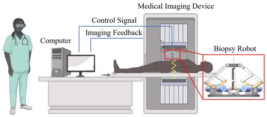
Figure 1.
Clinical application of needle biopsy robot.
1.2. Related Works
An effective design of robot-assisted needle biopsy system should be compact within confined spaces and provide adequate degrees of freedom (DoF) for the needle and ability to avoid obstacles during needle insertion [3]. Serial robots are favored for their simple structure and relatively larger workspace. The Cartesian platform is a straightforward serial robot structure capable of offering precise positioning functionality to surgical end-effectors. Consequently, it has garnered extensive research attention and found widespread application in the field. Su et al. designed an MRI-guided six-DoF robot for prostate treatment, consisting of a 3 DoF Cartesian platform and a three-DoF needle driving module [7]. Chen et al. designed a three-DoF focal laser ablation robot for prostate biopsy based on the modified Cartesian platform [8]. Recently, Li et al. introduced a six-DoF low back needle injection robot, which comprises two X–Y Cartesian planes that facilitate the control of the needle’s position and orientation angles [9]. Additionally, it includes a two-DoF needle driving module. Pan et al. used a similar robot structure and designed an eye-gaze-controlled needle injection robot [2,10]. It is noteworthy that the workspace of surgical robots based on Cartesian platforms is entirely determined by the axis length of the Cartesian platform, limiting their deployment within confined spaces, such as those encountered in medical imaging scanners. Custom-designed robotic structures are therefore proposed by researchers. Stoianovici et al. designed a four-DoF transrectal ultrasound-guided prostate biopsy robot based on the remote center of motion (RCM) serial mechanism [11]. Though the robot is compact and simple, its workspace is limited, and the end-effector must be adjusted manually. Nycz et al. combined the advantages from Cartesian platform and the RCM serial mechanism and designed a seven-DoF stereotactic neurosurgery robot to position, orient, and insert an interstitial ultrasound-based ablation needle [12]. To enlarge the reachable workspace while avoiding system cumbersomeness, Schreiber et al. designed a seven-DoF serial linkage robotic arm for CT-guided percutaneous needle lung biopsy [13]. This small in-bore sized robot features an expansive working area and numerous approach angles to targets. Cheng et al. designed a seven-DoF MRI-guided continuum neurosurgical robot [14]. Via selectively actuation of only 3 motors, this robot can achieve highly efficient end-effector re-configuration. Welleweerd et al. embedded a three-DoF needle insertion module and a US probe upon a seven-DoF commercially available robotic arm (KUKA MED 7 R800, KUKA, Sterling, VA, USA) to perform US-guided breast biopsy [15].
Compared with serial robots, parallel robots typically have a higher stiffness and rigidity, allowing them to maintain better positional accuracy and repeatability. Furthermore, the redundant connections and multiple supporting joints contribute to the ability to withstand external forces and maintain stability even in the event of component failures [16]. Eslami et al. designed a four-DoF parallel in-bore prostate transperineal intervention robot driven by MRI-compatible piezoelectric motors [17]. This robot uses lead screws to provide two-DoF Cartesian translations and two-DoF angulation motions for a needle. Yet, adequate improvement are necessary to make the system more compact. Orhan et al. designed a five-DoF parallel robot for US-guided percutaneous needle biopsy, which primarily consists of two four-link rhombus mechanisms [18]. Groenhuis et al. designed Stormram series robots for MRI-guided breast biopsy [5]. These robots use multiple-link parallel architectures to provide accurate and stable manipulator positions. Yet, since the Stormram series robots are actuated by customed design MRI-compatible pneumatic step motors, only position control is permitted. Moreira et al. designed a nine-DoF MRI-guided prostate needle insertion robot actuated by piezoelectric motors [19]. This robot consists of two parts, in which the control of the needle configuration is realized by the five-DoF parallel robot, and the function of rotating and inserting the biopsy needle is realized by the four-DoF needle driver. Wang et al. proposed a modularly designed six-DoF parallel robot specifically for image-guided surgeries. The robot’s modules are kinematically decoupled and can effectively expand its operational range, allowing for a larger workspace while occupying a smaller system size [20]. Stewart Gough Platform (SGP) is the most famous and well-studied six-DoF parallel mechanism. Chen et al. designed a 6-6 SGP surgical robot for MRI-guided needle intervention, utilizing a sliding mode control algorithm to govern the motion of pneumatic piston cylinders, thereby achieving the precise pose control of the mobile platform [21]. Huang et al. designed a 3-6 SGP needle biopsy robot for deep brain stimulation electrode implantation. It employs a crank-slider mechanism to convert the rotational motion of ultrasonic motors into linear motion [22]. However, the straight legs of an SGP inevitably restrict its system size, which is of significant importance within any medical imaging scanners. Comprehensive reviews about recent advancements in needle biopsy robots can be found in [1,3,23].
1.3. Brief Summary
Conclusively, recent advances in minimally invasive robot-assisted needle biopsy normally focus on custom design of robots for a specific intervention [24]. Many show deficiencies in operating area and reachable collision-free workspace, which precludes them from general purpose applications [13]. Additionally, with the well-accepted assumption that surgeries are preformed slowly [25], current works mainly focus on robot kinematic modeling and position control with image registration, without Jacobian analysis, which is especially critical for parallel robots to ensure the surgical robot works in a singularity-free workspace [26]. The Jacobian analysis also allows robot speed control to further improve the surgery progress.
To tackle these issues, this study presents a compact 6-DoF 3-RRRS parallel needle biopsy robot. The detailed design is presented in Section 2. Section 3 establishes the kinematic model, following by an analytical solution to its nonlinear kinematic problem, which allows fast and accurate feedback control calculations. Additionally, singularity analysis and a closed-form representation of singular conditions are presented in Section 4. A simulation model built within Matlab/Simulink using Simscape is established to verify the derived nonlinear kinematics in Section 5. Section 6 presents the experimental tests of a first-generation prototype to provide comprehensive verifications of the derived model and to evaluate the needle puncture process. Finally, Section 7 draws conclusive remarks. The main contributions of this study can be summarized as follows:
- (1)
- A kinematic model is established for a structure-specific parallel robot, which can be used to analytically solve its nonlinear kinematics problems and allows for fast and accurate feedback control calculations, including forward kinematics, inverse kinematics, and differential kinematics.
- (2)
- The correctness of the derivation kinematics is verified via a Simscape simulation model and a prototype. The results show that the model has high accuracy of robot calculation.
- (3)
- The first prototype was built based on simulation experiments. The rationality of the kinematic model we established was illustrated by demonstrating a puncture case.
2. Design of the 3-RRRS Parallel Needle Biopsy Robot
2.1. Mechanical Structure
The robot presented in this study adopts a three-chain parallel structure, illustrated in Figure 2. This three-chain parallel structure was mainly studied by Gosselin et al. [27,28] in the late 1990s. This robotic system comprises three identical five-bar parallelogram structures facilitating the connection between the moving platform and the base. There are also other configurations of three-chain six-DoF parallel robots, including the 3-RPSR [29], 3-CRS [30], 3-CPS [31], among others. In contrast to these alternatives, the structures utilized in this study feature distinctive support chains. Each support chain is linked to a moving platform through a combination of a universal joint and a revolute joint, mimicking a sphere joint, and a static platform at the base via a vertical rotating joint. To maintain symmetry, the connection points between the supporting chains and each platform are arranged in an equilateral triangle [20].
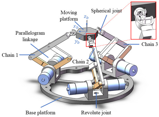
Figure 2.
Mechanical structure of the 3-RRRS Parallel Needle Biopsy Robot.
More specifically, each supporting chain in this design comprises a vertically oriented rotating joint, a five-bar parallelogram, and a spherical joint connected to the moving platform. It is worth noting that the five-bar parallelogram structure is kinematically similar to a planar double-rotation linkage mechanism, with the axis of rotation parallel to the horizontal plane. This design presents advantages compared to traditional parallel mechanisms, such as SGP, which typically employ six supporting chains with linear joints as drives. Conversely, the proposed configuration utilizes only three supporting chains, each equipped with two active rotary joints as the drive. This not only enhances the workspace but also contributes to a reduction in the overall volume of the robot.
2.2. Degree of Freedom Analysis
The degree of freedom of the robot can be determined by the Grübler–Kutzbach formula:
where denotes the number of links, g = 12 represents the number of joints, signifies the degree of freedom of joint k. Rotational joints have one DoF, and spherical joints have three DoF. Therefore, = 18. Following the calculations, the derived result indicates that the robot possesses six DoF.
2.3. Workspace Analysis
In most parallel mechanisms, there exists coupling between the drives, which adds complexity to the analysis of workspace. Currently, two primary methods are available for solving the workspace of parallel mechanisms. The first method involves geometric analysis, where the extreme positions and spatial constraints of specific parallel mechanisms are examined to derive geometric information about workspace boundaries [32]. The second method is a discretized approach, which involves dividing the extensive workspace into discrete segments. In this approach, inverse kinematics are solved for each node in the discrete space grid, and it is determined whether these positions satisfy mechanical constraints. Although this method is widely applicable to various types of parallel mechanisms and guarantees adherence to mechanical constraints, it demands considerable computational resources and lacks geometric details about workspace boundaries [33]. In this study, the geometric analysis method is chosen for determining the workspace of the parallel mechanism.
The Constant Orientation Workspace (COW) is defined as the collection of positions that the moving platform can attain while maintaining a consistent orientation. Figure 3 shows two examplary workspaces with different orientations. In this paper, the COW of the robot is determined by intersecting the individual workspaces of each chain and compensating for the offset of the moving platform. Taking into account the limitations imposed by the two active joints, the terminal attachment points are confined within the supporting plane, where . In scenarios where the active joint rotates to the limit position of the supporting chain, along with passive joint rotation, the terminal connection point is constrained to a sphere with a radius of around the point , as shown in Figure 4. Figure 3 illustrates the intersection of the motion spaces of each supporting chain, meeting the constraints of the moving platform and depicting the constant orientation workspace of the parallel mechanism. Notably, the lower half is practically unusable due to interference with the base; thus, only the upper half is depicted.
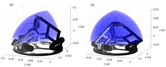
Figure 3.
Workspace of moving platform: (a) the moving platform maintains a positive z-axis direction, (b) the moving platform maintains a positive x-axis direction.
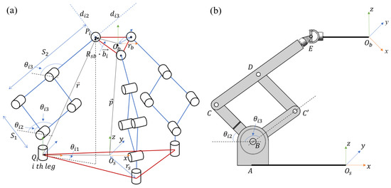
Figure 4.
Sketches of the robot: (a) kinematic analysis schematic diagram, (b) parallel robot supporting chain analysis schematic diagram.
3. Kinematic Modeling
3.1. Inverse Kinematics
The inverse kinematics of a parallel robot are traditionally addressed by analyzing vector loops constructed based on the mechanical structure. Advancing this approach, this paper introduces a more direct and intuitive method, capitalizing on the unique structure of the platform. This method entails determining the positions of the supporting chains and the 3 connection points on the moving platform through the configuration of the moving platform. Subsequently, this formulation is translated into an inverse kinematics problem for 3 serial robots. Figure 4 illustrates the placement of the fixed coordinate system {s} at the center point of the base platform and the mobile coordinate system {b} at the point on the moving platform. The connection points between the supporting chain and the two platforms can be represented in the respective coordinate systems {s} and {b} as follows:
where and represent the circumscribed circle radii of the base platform and the moving platform, respectively.
To solve the inverse kinematics for the robot, it is necessary to ascertain the rotation angles of the active joints within each supporting chain, a process dependent on the position and orientation of the moving platform. The elucidation of the specific solution method is detailed with reference to the geometric model diagram. The positional relationship between the moving platform and the stationary platform is represented by the vector .
Using three Euler angles to describe the orientation of the moving platform: roll (), pitch (), and yaw (). The positions of the joints connecting each chain to the moving platform relative to the center point of the base platform are
where is the rotation matrix of the moving platform in the base coordinate system, and this rotation matrix is given by the following equation
where , , represent the basic rotation transformations around the z, y, and x axes, respectively.
Since the passive joints at the connections between each chain and the base platform are rotary joints along the vertical z-axis direction, the point of the middle joint of the supporting chain, projected onto the xoy plane, lies on the line connecting the two platform connection points and , as shown in Figure 4b. For any supporting chain i, the equation can be written as
where and are angles of the two active rotational joints. By solving these equations simultaneously, the angles of the two active rotational joints in each chain can be determined analytically.
3.2. Forward Kinematics
The forward kinematics involve determining the moving platform’s motion based on the joint movements of the robot, specifically calculating the position and orientation of the moving platform from the robot’s joint coordinates. Forward kinematics are extremely important for feedback control based on information from the joint space sensor, as they can be used to calculate the position of the end platform. For parallel robotics, constructing kinematic models is inherently more intricate compared to serial robots. Gosselin et al. [34] previously addressed similar structures by separately considering each supporting chain and developing kinematic models based on screw theory. While this model is succinct, its derivation is complex, and the symbolic representation grounded in screw theory lacks intuitiveness. Therefore, in this paper, a more straightforward and efficient model is formulated, starting from the geometric characteristics of the robot structure.
For the six-DoF parallel robot in this paper, we need to calculate the moving platform’s pose and configuration based on the values of the active joint angles , for each chain, where .
The specific calculation process is provided in the Appendix A, and detailed calculations are not included here.
According to the calculation of the forward kinematics model, the coordinates of the connection point between the support chain and the end of the mobile platform can be obtained, which are denoted as . The position of the moving platform can therefore be obtained as
If there is no rotation around the z-axis of the moving platform, the direction of the moving platform can be represented by the normal vector
Based on the direction of the moving platform and the initial orientation, the rotation angle and rotation axis can be calculated.
Using Rodrigues’ formula, the corresponding rotation matrix can be calculated.
If there is any rotation component around the z-axis of the moving platform, the positive kinematics solving problem can be translated into finding the optimal rotation and translation transformation between the corresponding 3D points. This problem can be solved by the method of singular value decomposition (SVD).
where , , , , is an operation that subtracts each column in N by [35].
There is a special case when using SVD to calculate the rotation matrix. If , the resulting rotation matrix is numerically correct, but it is actually trivial in reality. For this case, we need to multiply −1 in the third column of V to obtain the correct R.
3.3. Jacobian Matrix and Velocity-Level Kinematics
Considering that controlling robots often involves modifying joint motion velocities or adjusting joint torques, the significance of the Jacobian matrix in linking joint space to workspace becomes crucial in the context of robot motion control. The derivation of the Jacobian matrix entails velocity loop analysis, where the velocity loops result directly from differentiating kinematic loops. At the displacement level, each motion loop can be concisely expressed in vector form. The number of loops is determined by the number of chains, which is three in this case. The formula for motion loops [26] is expressed as follows:
When converted into scalar equations, the above equation can be written as
Differentiating both sides of the equation, it yields
The second term of the equation can be written as
Equation (16) can be rewritten as
According to the velocity equation of the robot’s motion loop, the relationship between the moving platform’s motion twist and the velocity of the connection points on the moving platform can be obtained. Then, based on the kinematic analysis of the supporting chains, the velocity of the connection points on the moving platform can be expressed in terms of the angular velocities of the active joints, resulting in the global Jacobian matrix of the parallel robot. The specific calculation process is provided in the Appendix A, and here we directly present the results:
where, ,. Equation (19) represents the velocity-level kinematic equation of the parallel robot. It can be observed that both matrices K and have dimensions of . The dimensions of the matrices indicate that the mechanism is a non-redundant robot with six DoF and six actuators.
4. Singularity Analysis
In general, parallel robots commonly encounter singular configurations, which occur when any matrix in Equation (19) becomes singular, as revealed by the analysis of differential kinematics. The robot’s performance sharply deteriorates when operating near a singular configuration, making it uncontrollable in such states. Singularity emerges as a primary constraint limiting the orientational workspace of parallel robots. To address these challenges, singularity analysis becomes a crucial step in the design process of robot mechanisms. Previous studies have introduced various methods for analyzing the singularities of parallel robots, including approaches based on screw theory and Grassmann line geometry [27], among others. Following the analysis method proposed by Gosselin et al. [36], singularities in parallel robots can be categorized into distinct types, such as chain singularity, platform singularity, etc.
4.1. Chain Singularity
The chain singularity analysis of a three-chain parallel robot is equivalent to the singularity analysis of three serial-type robots, each with three DoF. Therefore, we can derive the geometric conditions for chain singularities. In the spatial coordinate system, the screw system of the i th supporting chain in the parallel robot can be represented as
where , , , and represent the unit vectors in the x-axis direction, y-axis direction, and z-axis direction, respectively. The condition for supporting chain singularity is when is linearly dependent, which can be determined by the determinant of :
Solving Equation (21), we get . This means that the supporting chain singularity of the parallel robot occurs when links and are collinear, as shown in Figure 5a.
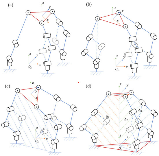
Figure 5.
Illustration of different types of singularities. (a) Chain singularity. (b) Platform singularity case 1. (c) Platform singularity case 2. (d) Platform singularity case 3.
4.2. Platform Singularity
When the matrix in the velocity-level kinematic equation Equation (19) of the parallel robot becomes singular, the moving platform possesses a singular configuration. In such a state, determining the passive joint velocities and the velocity of the moving platform from the active joint velocities, or vice versa, becomes impossible [37]. In principle, when the angles of active and passive joints are known, the singularity configuration can be identified by calculating the determinant of the matrix in Equation (19). Moreover, considering the specific parallel robot structure in this study, geometric conditions for platform singularities can be analyzed using Grassmann line geometry.
- (1)
- If any passive joint axis passes precisely through its corresponding attachment point on the moving platform, a platform singularity occurs, as illustrated in Figure 5b. In this scenario, the velocity contribution of this passive joint to the velocity of the platform connection point diminishes. This singularity configuration is a consequence of particular robot structures and manifests across all configurations within the entire robot workspace. Therefore, this structural singularity can be circumvented through meticulous design considerations.
- (2)
- Considering the case where three driving links align in a straight line within a shared plane: Let and represent lines parallel to the driving links that traverse through point . A singularity configuration arises when line or of the jth supporting chain is part of supporting chain plane i and passes through point . Consequently, lines or must align with the edge of the moving platform. This circumstance is only realized when planes i and j coincide, as depicted in Figure 5c.
- (3)
- Considering the scenario of three interrelated supporting chains: when the constraint forces of the three supporting chains exhibit linear dependence, according to Grassmann linear geometry, it can be elucidated that the three supporting chain planes , , and share a common intersection line, as illustrated in Figure 5d. When the normal vectors of the three planes 1, 2 and 3 are coplanar, it satisfiesAccording to Equation (22), the conditions for the occurrence of such singularity are
5. Simulation Experiments
5.1. Simulation Platform Setup
To demonstrate the accuracy of the derived position-level and velocity-level kinematic models, we have established a numerical simulation model for validation. The main dimensional parameters of the parallel robot are set according to the requirements of the customized puncture surgery. The workspace in clinical surgery is small, so with reference to the workspace analysis shown in Figure 3, we give the main dimensional parameters of the robot as shown in Table 1. The 3D CAD assembly file of the robot is imported into Matlab/Simulink using Simscape toolbox (see Figure 6), which provides a comprehensive multibody dynamic library. Given a desired trajectory of the moving platform, inverse kinematics is calculated first and resulting joint trajectories are sent to the Simscape robot model next. The trajectory of the moving platform is then continuously simulated and captured, which is compared with the calculation results based on the previously derived forward kinematic model and the differential kinematic model.

Table 1.
Main dimensional parameters of the proposed robot.
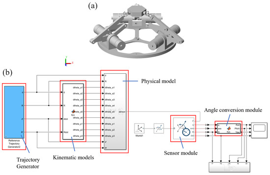
Figure 6.
(a) Matlab/Simscape virtual robot. (b) Simulink block model.
5.2. Simulation Test
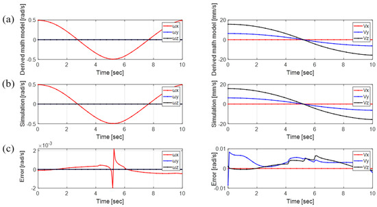
To comprehensively and thoroughly verify the derived robotic model, three trajectories for the moving platform are studied. More specifically, and gives time-varying trajectories for the moving platform’s position in z and y directions, respectively. assigns a time-varying trajectory for the moving platform’s orientation around x-axis. This is shown in Figure 7, Figure 8 and Figure 9. Here, represents the rotational velocity of the moving platform, and signifies the translational velocity of the moving platform.
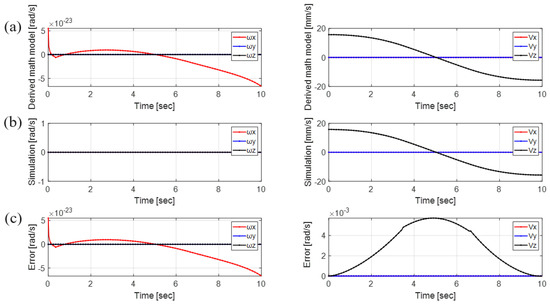
Figure 7.
Moving platform’s velocity comparison: translational trajectory along the z-axis: . (a) Derived model, (b) simscape simulation, (c) error.
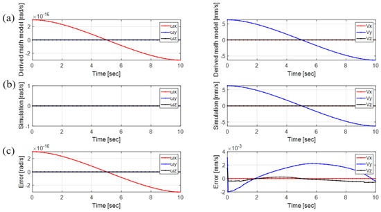
Figure 8.
Moving platform’s velocity comparison: translational trajectory along the y-axis: . (a) Derived model, (b) simscape simulation, (c) error.
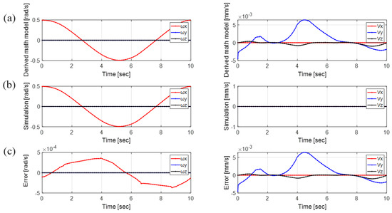
Figure 9.
Moving platform’s velocity comparison: rotational trajectory along the x-axis: . (a) Derived model, (b) simscape simulation, (c) error.
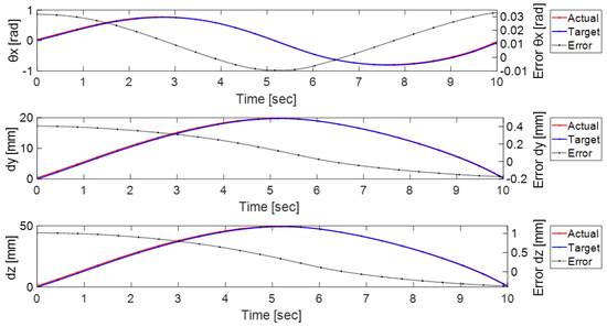
Figure 10 demonstrate the moving platform’s 6 DoF velocity comparison between the proposed kinematic model and the simulation when the robot follows the combined trajectory specified by Equations (24)–(26). The results are integrated to acquire moving platform’s six-DoF configuration, as shown in Figure 11. Notably, both the speed and position errors are observed to be adequate small, meaning the derived kinematic model shows great accuracy.
6. Prototype Experiments
6.1. Prototype Platform Setup
Figure 12a presents the first-generation prototype of the robot proposed in this study. An experimental investigation is devised to evaluate the kinematic model and explore the kinematic characteristics of the parallel robot. The experimental platform of the 3-RRRS parallel robot is designed according to the simulation model, and the size of the prototype is consistent with the simulation, as shown in Table 1. Following this, the hardware and software structure of the control system are developed. Specifically, the main body of the robot is manufactured using 3D printing, and the support structure is assembled using standard 2020 aluminum profiles. The motors employed are the RoboMaster M2006 P36 BLDC geared motors (DJI Technology Co., Ltd., Shenzhen, China), paired with the C610 electronic speed control (DJI Technology Co., Ltd., Shenzhen, China). In this scenario, the RoboMaster A-type development board (SZ DJI Technology Co., Ltd., Shenzhen, China) is used as the main controller, all motors communicate with the master controller through the CAN bus, and the closed-loop control frequency of each motor is maintained at 1000 Hz. At the same time, the master controller and the host computer exchange data through the USB bus, and the frequency of its communication is 100 Hz. The master controller uploads the position information of each motor to the host computer in real time, and the host computer sends the target position of each motor to the master controller. Remarkably, the motor gearbox features a reduction ratio of 36:1, boasting attributes such as high output speed, compact size, and elevated power density. To evaluate control accuracy, computer vision techniques are utilized to capture the position and orientation of the moving platform within the workspace, subsequently comparing these values with the pose of the moving platform derived from joint space calculations.
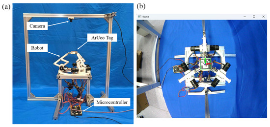
Figure 12.
(a) Photo of the experiment setup. (b) Real-time robot configuration measurement based on ArUco tag.
6.2. Realtime Robot Configuration Measurement Based on ArUco Tag
Currently, there lacks a sensor for the moving platform of a parallel robot in general which can accurately measure its real-time motion. To evaluate the robot’s performance in the experiment, a vision-based pose estimation method was developed.
The monocular vision method is utilized to estimate pose and configuration, specifically employing the ArUco binary square reference marker [38,39]. The ArUco tag is predominantly employed for the detection of planar markers and the estimation of the target’s pose concerning the camera. Its key advantages include easy detection, rapid processing, and high robustness. A camera is positioned above the prototype to capture the configuration of the moving platform within the plane. The ArUco tag is affixed to the end platform to provide pose information for the moving platform. Utilizing the relative pose relationship between the ArUco tag on the terminal platform and the camera, the robot’s pose relative to the initial configuration can be determined. The camera parameters were obtained through MATLAB (version: 9.14.0.2286388 (R2023a) Update 3) calibration program. Chessboard images taken from multiple angles were used to calculate the camera matrix using Zhengyou Zhang’s calibration method [40]. The specific data are listed in Table 2. Figure 12b delineates the process of ArUco tag detection.
Table 2.
Main parameters of the camera calibration.
6.3. Experiment Results
To verify the correctness of the kinematic model, the prototype is utilized to conduct experiments. The trajectories of translational motion and rotational motion are combined with those simulated in Equations (24)–(26), so as to better verify the model with the experimental results of the prototype. In contrast to simulations, all measurements in the experiment have been transformed from the camera coordinate system to the robot coordinate system. The camera coordinate system is positioned 0.2 m along the z-axis from the initial position of the motion platform and rotated 180° around the x-axis. Therefore, the homogeneous transformation matrix for the ArUco tag coordinate system relative to the camera coordinate system is denoted as . Comparative plots of the moving platform’s rotational and translational trajectories along the x, y, and z axes are depicted in Figure 13.
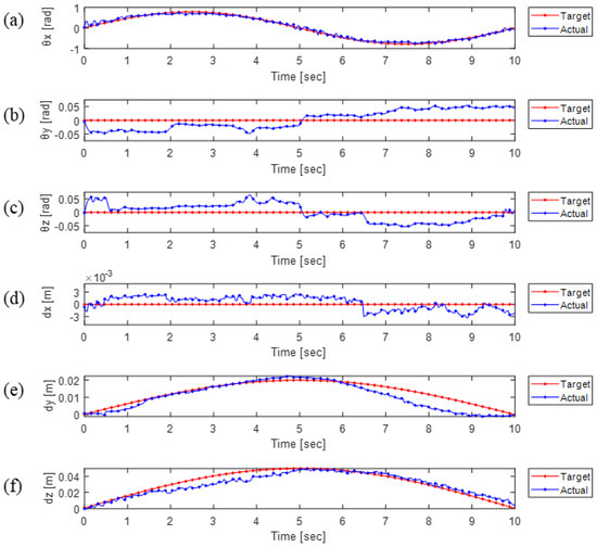
Figure 13.
Moving platform’s motion test: (a) rotational angle around x-axis, (b) rotational angle around y-axis, (c) rotational angle around z-axis, (d) translational distance along x-axis, (e) translational distance along y-axis, (f) translational distance along z-axis.
Figure 13 compares the motion trajectory of the prototype obtained through computer vision with the desired trajectory. The red curve represents the expected trajectory pose of the moving platform, while the blue curve depicts the calculated one based on the ArUco tag. The first three curves (a), (b), and (c) illustrate the changes in the platform’s orientation during motion, represented by the angles, while the last three curves (d), (e), and (f) represent the position vector.
Upon comparing the experimental results of the prototype with those of the simulation model, taking into account various errors stemming from prototype assembly, camera calibration, and ArUco tag recognition, it is observed that the trajectory error exceeds that observed in the simulated motion trajectory. However, it is important to note that the primary objective of this experiment is to verify the proposed robotic model, utilizing solely open-loop control. The average position error is reported to be within ±2.5 mm, with an average angle error of less than ±2.86°. To improve tracking performance, the implementation of more advanced control algorithms is recommended to ensure the accuracy of motion trajectory tracking.
6.4. Puncture Experiment Results
To demonstrate the practical applicability of the parallel robot in puncture surgery, subsequent to verifying the trajectory tracking capability of both the kinematic model and the prototype, we devised an experiment to simulate the puncture process in a medical scenario.
The experiment utilized a transparent cubic container measuring to contain soft silicone jelly, simulating human tissue for puncture. A fine tube was inserted to indicate the puncture direction and the puncture target points.
In the experiment, the position of the puncture entry point and the target point were determined in advance, from which the puncture orientation was calculated. This information is fed to the robot for a puncture movement. The experiment was simplified and divided into two phases. The first stage involves positioning the robot’s terminal platform to the initial puncture position and aligning the puncture with the target direction. The second stage requires moving the robot in the direction of the needle towards the target position while maintaining the same orientation. Subsequently, 20 punctures were performed on the same target, which were evaluated at the end of the procedure. Figure 14 illustrates the process of a representative puncture experiment.
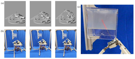
Figure 14.
One representative puncture experiment process (the initial puncture position is (0,0,60) and the puncture end position is (0,10,77.32)): (a) simulated puncture process. (b) prototype puncture process. (c) the result of a successful puncture with a small error.
Upon the conclusion of the experiment, the comprehensive statistics of all results are depicted in Figure 15. Error data from 20 replicate experiments is depicted in the boxplot. In the figure, the red dots represent data error points. , , and represent the errors between the direction of the needle insertion and the desired direction represented by the angles, respectively, over 20 repeated experiments. , , and represent the errors in the needle insertion position. The findings indicate minimal errors in both position and direction during simulated puncture surgery, affirming the feasibility of the parallel puncture robot design. The main reason for the errors in the experiment is the insufficient processing accuracy of the 3D printed parts and the accumulation of errors between joint connections. Since the main focus of this paper is on model establishment and validation, only simple open-loop control was used for position control in the experiment. When the robot is used for puncture in the future, advanced control algorithms can be added to improve the accuracy.
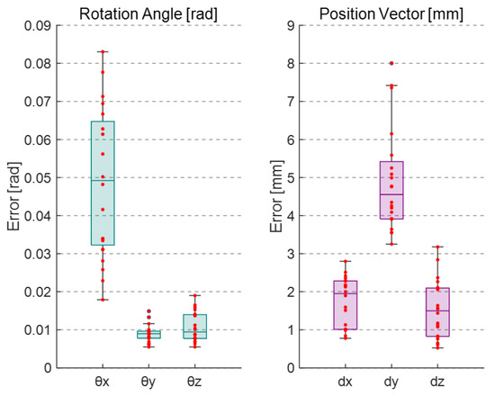
Figure 15.
The puncture experiment results: error data from five replicate experiments.
7. Conclusions
In this paper, we introduce a 6-DoF 3-RRRS parallel robot designed as a versatile platform for needle biopsy procedures. Unlike previous works, this robot offers a relatively large workspace within a compact footprint. We provide a thorough analysis of the robot, covering its structure, nonlinear kinematics, and singularity aspects. Through a combination of simulation studies and experimental validations, we systematically evaluate the performance of the proposed robot. We also have listed some representative biopsy robots and compared them in terms of type, degrees of freedom, control mode, and other aspects in Table 3. Our findings contribute to a comprehensive understanding of the robot’s capabilities and its suitability for medical applications.
Table 3.
Comparison of the medical robots for needle biopsy surgery.
However, several avenues for future research remain open. One key area is the integration of advanced control algorithms to improve the robot’s efficiency and movement precision. Additionally, there is a need for optimal trajectory planning that avoids singularities in the robot’s motion. Addressing these challenges presents opportunities for further investigation and enhancement in future research endeavors.
Author Contributions
Conceptualization, J.W.; methodology, R.X. and J.X.; software, B.W.; validation, X.W., M.C. and Z.P.; investigation, M.L. and J.W.; writing—original draft preparation, J.W.; writing—review and editing, M.L. and X.L. All authors have read and agreed to the published version of the manuscript.
Funding
The author disclosed receipt of the following financial support for the research, authorship, and/or publication of this article: This work was supported by the Foundation for Shenzhen Science and Technology Program (Grant No. RCBS20221008093104018) and Guangdong Basic and Applied Basic Research Foundation (Grant No. 2023A1515110440).
Data Availability Statement
Data are contained within the article.
Acknowledgments
The CAD files for the proposed 6-DoF 3-RRRS robot, along with the SimScape simulation models, are available from the corresponding author Li, M. upon request.
Conflicts of Interest
The authors declare no conflicts of interest.
Notation
| Position vector of point relative to base platform | |
| Position vector of point relative to moving platform | |
| Position vector of point relative to base platform | |
| c | Number of parts in the mechanism |
| Line parallel to the driving links that traverse through point | |
| Degrees of freedom of joint k | |
| Singular value decomposition correlation matrix | |
| g | Number of joints |
| Jacobian coefficient matrix | |
| m | Degrees of freedom |
| Set of 3D points connected to the moving platform | |
| Direction of the moving platform represented by the normal vector | |
| Position vector of moving platform relative to base platform | |
| Attachment point between chain and platform | |
| Attachment point between chain and base | |
| Circumscribed circle radii of the moving platform | |
| Circumscribed circle radii of the base platform | |
| relative to base platform | |
| Velocity of the connection point of the moving platform | |
| Velocity component of perpendicular to the supporting chain plane | |
| Rotation matrix of moving platform relative to base platform | |
| Length of connecting rod i | |
| Homogeneous transformation matrix of the ArUco tag coordinate system relative to the camera | |
| Unit vector in the x-axis direction of chain i | |
| Rotation angle of the moving platform around the rotation axis | |
| Active rotational joint angle | |
| Passive rotational joint angle of chain i | |
| Active rotational joint angle of chain i | |
| Rotation matrix of moving platform relative to base platform | |
| Rotating axis of the moving platform | |
| Screw system of the i th supporting chain | |
| The plane in which supporting chain i is located | |
| Euler angle describing the direction of the moving platform |
Appendix A
Appendix A.1. Calculation of the forward Kinematics Model
After determining the angle of the active joints, the height of each support chain can be uniquely determined. However, the value of the passive joint angle needs to be determined by the constraints imposed by the connection of the three chains to the moving platform. Consider a single support chain, the coordinates of the end attachment points to the moving platform of which are given by . The height of the end of the chain can be calculated as follows:
The trajectory of the chain’s end point as it varies with the passive joint angle can be represented using the parametric equation of a circle:
where t . Subsequently, considering the constraint relationships between the connection points on the moving platform, we have
From this, the coordinates of the connection points on the moving platform can be calculated.
Appendix A.2. Jacobian Analysis of Differential Kinematics
According to Equation (18), the velocity loops of the three supporting chains in parallel can be rewritten as a matrix:
where, , , .
Considering the relationship between and , due to the equilateral triangular structure of the moving platform, differentiating Equation (8) yields the following relationship between the moving platform velocity and the velocities of the three connection points , and :
By simultaneously combining the three equations in Equation (A7), we can modify the matrices and to be
For the right side of Equation (18), each chain can be analyzed separately as a three-DoF serial robot, represented in the chain coordinate system as
Take the derivative with respect to time, which yields
Due to the robotic structural characteristics, the rotational motion of the passive joint generates velocity only perpendicular to the supporting chain plane at the end, while the rotations of active joints and produce velocities parallel to the supporting chain plane at the end. Therefore, consider , the velocity component perpendicular to the supporting chain plane at the end, represented through vector decomposition:
Next, express through the rotation joint
Hence, the following can be obtained:
Substitute it into Equation (A9), which yields
where ,
, .
Substituting the above into Equation (A8), we can have
where , .
According to the vector representation of the supporting chain end points in the base coordinate system, the distance constraints of the three connection points can be expressed as
The derivative of Equation (A17) can be written as
Hence, the following can be obtained:
Let ; thus, we have
Substitute it into Equation (A6), which yields .
References
- Su, H.; Kwok, K.W.; Cleary, K.; Iordachita, I.; Cavusoglu, M.C.; Desai, J.P.; Fischer, G.S. State of the art and future opportunities in MRI-guided robot-assisted surgery and interventions. Proc. IEEE 2022, 110, 968–992. [Google Scholar] [CrossRef] [PubMed]
- Pan, Z.; Zhu, J.; Zhang, J.; Li, W.; Jia, G.; Luo, W.; Peng, J.; Li, M. An Eye Gaze Controlled Needle Deployment Robot: Design, Modeling and Experimental Evaluation. IEEE Trans. Instrum. Meas. 2024, 73, 3370751. [Google Scholar] [CrossRef]
- Siepel, F.J.; Maris, B.; Welleweerd, M.K.; Groenhuis, V.; Fiorini, P.; Stramigioli, S. Needle and biopsy robots: A review. Curr. Robot. Rep. 2021, 2, 73–84. [Google Scholar] [CrossRef]
- D’Souza, M.; Gendreau, J.; Feng, A.; Kim, L.H.; Ho, A.L.; Veeravagu, A. Robotic-assisted spine surgery: History, efficacy, cost, and future trends. Robot. Surg. Res. Rev. 2019, 6, 9–23. [Google Scholar] [CrossRef] [PubMed]
- Groenhuis, V.; Veltman, J.; Siepel, F.J.; Stramigioli, S. Stormram 3: A magnetic resonance imaging-compatible robotic system for breast biopsy. IEEE Robot. Autom. Mag. 2017, 24, 34–41. [Google Scholar] [CrossRef]
- Stoianovici, D.; Kim, C.; Petrisor, D.; Jun, C.; Lim, S.; Ball, M.W.; Ross, A.; Macura, K.J.; Allaf, M.E. MR safe robot, FDA clearance, safety and feasibility of prostate biopsy clinical trial. IEEE/ASME Trans. Mechatron. 2016, 22, 115–126. [Google Scholar] [CrossRef] [PubMed]
- Su, H.; Zervas, M.; Cole, G.A.; Furlong, C.; Fischer, G.S. Real-time MRI-guided needle placement robot with integrated fiber optic force sensing. In Proceedings of the 2011 IEEE International Conference on Robotics And Automation, Shanghai, China, 9–13 May 2011; IEEE: Piscataway, NJ, USA, 2011; pp. 1583–1588. [Google Scholar]
- Chen, Y.; Squires, A.; Seifabadi, R.; Xu, S.; Agarwal, H.K.; Bernardo, M.; Pinto, P.A.; Choyke, P.; Wood, B.; Tse, Z.T.H. Robotic system for MRI-guided focal laser ablation in the prostate. IEEE/ASME Trans. Mechatron. 2016, 22, 107–114. [Google Scholar] [CrossRef]
- Li, G.; Patel, N.A.; Liu, W.; Wu, D.; Sharma, K.; Cleary, K.; Fritz, J.; Iordachita, I. A fully actuated body-mounted robotic assistant for mri-guided low back pain injection. In Proceedings of the 2020 IEEE International Conference on Robotics and Automation (ICRA), Paris, France, 31 May–31 August 2020; IEEE: Piscataway, NJ, USA, 2020; pp. 5495–5501. [Google Scholar]
- Pan, Z.; Jia, G.; Zhu, J.; Wang, J.; Luo, W.; Li, M. Design and Implementation of A Novel 4-DoF Robot for Assisted Needle Puncture Deployment. In Proceedings of the 2023 International Conference on Frontiers of Robotics and Software Engineering (FRSE), Changsha, China, 16–18 June 2023; IEEE: Piscataway, NJ, USA, 2023; pp. 9–15. [Google Scholar]
- Stoianovici, D.; Kim, C.; Schäfer, F.; Huang, C.M.; Zuo, Y.; Petrisor, D.; Han, M. Endocavity ultrasound probe manipulators. IEEE/ASME Trans. Mechatron. 2012, 18, 914–921. [Google Scholar] [CrossRef]
- Nycz, C.J.; Gondokaryono, R.; Carvalho, P.; Patel, N.; Wartenberg, M.; Pilitsis, J.G.; Fischer, G.S. Mechanical validation of an MRI compatible stereotactic neurosurgery robot in preparation for pre-clinical trials. In Proceedings of the 2017 IEEE/RSJ International Conference on Intelligent Robots and Systems (IROS), Vancouver, BC, Canada, 24–28 September 2017; IEEE: Piscataway, NJ, USA, 2017; pp. 1677–1684. [Google Scholar]
- Schreiber, D.A.; Shak, D.B.; Norbash, A.M.; Yip, M.C. An open-source 7-axis, robotic platform to enable dexterous procedures within CT scanners. In Proceedings of the 2019 IEEE/RSJ International Conference on Intelligent Robots and Systems (IROS), Macau, China, 3–8 November 2019; IEEE: Piscataway, NJ, USA, 2019; pp. 386–393. [Google Scholar]
- Cheng, S.S.; Wang, X.; Jeong, S.; Kole, M.; Roys, S.; Gullapalli, R.P. Mechanical design and evaluation of a selectively-actuated MRI-compatible continuum neurosurgical robot. In Proceedings of the 2021 IEEE/RSJ International Conference on Intelligent Robots and Systems (IROS), Prague, Czech Republic, 27 September–1 October 2021; IEEE: Piscataway, NJ, USA, 2021; pp. 2498–2503. [Google Scholar]
- Welleweerd, M.K.; Siepel, F.J.; Groenhuis, V.; Veltman, J.; Stramigioli, S. Design of an end-effector for robot-assisted ultrasound-guided breast biopsies. Int. J. Comput. Assist. Radiol. Surg. 2020, 15, 681–690. [Google Scholar] [CrossRef]
- Gosselin, C.; Merlet, J. Parallel robots: Architecture, modeling, and design. In Encyclopedia of Robotics; Springer: Berlin/Heidelberg, Germany, 2020; pp. 1–6. [Google Scholar]
- Eslami, S.; Shang, W.; Li, G.; Patel, N.; Fischer, G.S.; Tokuda, J.; Hata, N.; Tempany, C.M.; Iordachita, I. In-bore prostate transperineal interventions with an MRI-guided parallel manipulator: System development and preliminary evaluation. Int. J. Med Robot. Comput. Assist. Surg. 2016, 12, 199–213. [Google Scholar] [CrossRef]
- Orhan, S.O.; Yildirim, M.C.; Bebek, O. Design and modeling of a parallel robot for ultrasound guided percutaneous needle interventions. In Proceedings of the IECON 2015-41st Annual Conference of the IEEE Industrial Electronics Society, Yokohama, Japan, 9–12 November 2015; IEEE: Piscataway, NJ, USA, 2015; pp. 005002–005007. [Google Scholar]
- Moreira, P.; van de Steeg, G.; Krabben, T.; Zandman, J.; Hekman, E.E.; van der Heijden, F.; Borra, R.; Misra, S. The miriam robot: A novel robotic system for mr-guided needle insertion in the prostate. J. Med. Robot. Res. 2017, 2, 1750006. [Google Scholar] [CrossRef]
- Wang, X.; Ye, Y.; Pan, Z.; Wang, J.; Guo, R.; Li, M. Design and Kinematic Analysis of a 6-DoF Parallel Robot for Image-Guided Surgery. In Proceedings of the 2023 China Automation Congress (CAC), Chongqing, China, 17–19 November 2023; IEEE: Piscataway, NJ, USA, 2023; pp. 2677–2682. [Google Scholar]
- Musa, M.; Sengupta, S.; Chen, Y. Design of a 6 dof parallel robot for mri-guided interventions. In Proceedings of the 2021 International Symposium on Medical Robotics (ISMR), Atlanta, GA, USA, 17–19 November 2021; IEEE: Piscataway, NJ, USA, 2021; pp. 1–7. [Google Scholar]
- Huang, W.; Dai, S.; Xu, A.; He, X.; Huang, S.; Gao, A. Pneumatically actuated mr-safe parallel robot for deep brain stimulation electrode implantation. In Proceedings of the 2021 IEEE International Conference on Robotics and Biomimetics (ROBIO), Sanya, China, 27–31 December 2021; IEEE: Piscataway, NJ, USA, 2021; pp. 1743–1748. [Google Scholar]
- Monfaredi, R.; Cleary, K.; Sharma, K. MRI robots for needle-based interventions: Systems and technology. Ann. Biomed. Eng. 2018, 46, 1479–1497. [Google Scholar] [CrossRef]
- Michiels, C.; Jambon, E.; Bernhard, J. Measurement of the accuracy of 3D-printed medical models to be used for robot-assisted partial nephrectomy. Am. J. Roentgenol. 2019, 213, 626–631. [Google Scholar] [CrossRef] [PubMed]
- Li, M. Design and stability analysis of a nonlinear controller for MRI-compatible pneumatic motors. Proc. Inst. Mech. Eng. Part C J. Mech. Eng. Sci. 2024, 238, 3–17. [Google Scholar] [CrossRef]
- Taghirad, H.D. Parallel Robots: Mechanics and Control; CRC Press: Boca Raton, FL, USA, 2013. [Google Scholar]
- Monsarrat, B.; Gosselin, C.M. Singularity analysis of a three-leg six-degree-of-freedom parallel platform mechanism based on Grassmann line geometry. Int. J. Robot. Res. 2001, 20, 312–328. [Google Scholar] [CrossRef]
- Monsarrat, B.; Gosselin, C.M. Workspace analysis and optimal design of a 3-leg 6-DOF parallel platform mechanism. IEEE Trans. Robot. Autom. 2003, 19, 954–966. [Google Scholar] [CrossRef]
- Takeda, Y.; Xiao, X.; Hirose, K.; Yoshida, Y.; Ichiryu, K. Kinematic analysis and design of 3-RPSR parallel mechanism with triple revolute joints on the base. Int. J. Autom. Technol. 2010, 4, 346–354. [Google Scholar] [CrossRef]
- Nguyen, A.V.; Bouzgarrou, B.C.; Charlet, K.; Béakou, A. Static and dynamic characterization of the 6-Dofs parallel robot 3CRS. Mech. Mach. Theory 2015, 93, 65–82. [Google Scholar] [CrossRef]
- Li, W.; Angeles, J. A novel three-loop parallel robot with full mobility: Kinematics, singularity, workspace, and dexterity analysis. J. Mech. Robot. 2017, 9, 051003. [Google Scholar] [CrossRef]
- Yiğit, A.; Breton, D.; Zhou, Z.; Laliberté, T.; Gosselin, C. Kinematic Analysis and Design of a Novel (6+ 3)-DoF Parallel Robot with Fixed Actuators. In Proceedings of the 2023 IEEE International Conference on Robotics and Automation (ICRA), London, UK, 29 May–2 June 2023; IEEE: Piscataway, NJ, USA, 2023; pp. 9693–9699. [Google Scholar]
- Chen, Y.; Godage, I.S.; Sengupta, S.; Liu, C.L.; Weaver, K.D.; Barth, E.J. MR-conditional steerable needle robot for intracerebral hemorrhage removal. Int. J. Comput. Assist. Radiol. Surg. 2019, 14, 105–115. [Google Scholar] [CrossRef]
- Ebert-Uphoff, I.; Gosselin, C.M. Kinematic study of a new type of spatial parallel platform mechanism. In Proceedings of the International Design Engineering Technical Conferences and Computers and Information in Engineering Conference, Atlanta, GA, USA, 13–16 September 1998; American Society of Mechanical Engineers: New York, NY, USA, 1998; Volume 80302, p. V01AT01A020. [Google Scholar]
- Akritas, A.G.; Malaschonok, G.I. Applications of singular-value decomposition (SVD). Math. Comput. Simul. 2004, 67, 15–31. [Google Scholar] [CrossRef]
- Kim, J.; Gosselin, C. A Kinematically Redundant (6+ 1)-dof Hybrid Parallel Robot for Delicate Physical Environment and Robot Interaction (pERI). In Proceedings of the 2023 IEEE International Conference on Robotics and Automation (ICRA), London, UK, 29 May–2 June 2023; IEEE: Piscataway, NJ, USA, 2023; pp. 9679–9685. [Google Scholar]
- Slavutin, M.; Shai, O.; Sheffer, A.; Reich, Y. A novel criterion for singularity analysis of parallel mechanisms. Mech. Mach. Theory 2019, 137, 459–475. [Google Scholar] [CrossRef]
- Chen, Q.; Li, M.; Wu, H.; Liu, W.; Peng, J. Design, self-calibration and compliance control of modular cable-driven snake-like manipulators. Mech. Mach. Theory 2024, 193, 105562. [Google Scholar] [CrossRef]
- Qiu, Q.; Zhu, J.; Gou, C.; Li, M. Eye gaze estimation based on stacked hourglass neural network for aircraft helmet aiming. Int. J. Aerosp. Eng. 2022, 2022. [Google Scholar] [CrossRef]
- Zhang, Z. Flexible camera calibration by viewing a plane from unknown orientations. In Proceedings of the Seventh IEEE International Conference on Computer Vision, Kerkyra, Greece, 20–27 September 1999; IEEE: Piscataway, NJ, USA, 1999; Volume 1, pp. 666–673. [Google Scholar]
- Zhu, J.H.; Wang, J.; Wang, Y.G.; Li, M.; Guo, Y.X.; Liu, X.J.; Guo, C.B. Performance of robotic assistance for skull base biopsy: A phantom study. J. Neurol. Surg. Part B Skull Base 2017, 78, 385–392. [Google Scholar] [CrossRef] [PubMed]
- Carai, A.; Mastronuzzi, A.; De Benedictis, A.; Messina, R.; Cacchione, A.; Miele, E.; Randi, F.; Esposito, G.; Trezza, A.; Colafati, G.S.; et al. Robot-assisted stereotactic biopsy of diffuse intrinsic pontine glioma: A single-center experience. World Neurosurg. 2017, 101, 584–588. [Google Scholar] [CrossRef] [PubMed]
- Groenhuis, V.; Siepel, F.J.; Veltman, J.; van Zandwijk, J.K.; Stramigioli, S. Stormram 4: An MR safe robotic system for breast biopsy. Ann. Biomed. Eng. 2018, 46, 1686–1696. [Google Scholar] [CrossRef] [PubMed]
- Navarro-Alarcon, D.; Singh, S.; Zhang, T.; Chung, H.L.; Ng, K.W.; Chow, M.K.; Liu, Y. Developing a compact robotic needle driver for MRI-guided breast biopsy in tight environments. IEEE Robot. Autom. Lett. 2017, 2, 1648–1655. [Google Scholar] [CrossRef]
- Zhang, T.; Wen, Y.; Liu, Y.H. Developing a parallel robot for MRI-guided breast intervention. IEEE Trans. Med Robot. Bionics 2019, 2, 17–27. [Google Scholar] [CrossRef]
- Liu, W.; Yang, Z.; Jiang, S.; Feng, D.; Zhang, D. Design and implementation of a new cable-driven robot for MRI-guided breast biopsy. Int. J. Med Robot. Comput. Assist. Surg. 2020, 16, e2063. [Google Scholar] [CrossRef]
- Zhang, Y.; Shi, C.; Du, H.; Gu, B.; Yu, Y. A MRI compatible robot for breast intervention. In Proceedings of the 2015 IEEE International Conference on Robotics and Biomimetics (ROBIO), Zhuhai, China, 6–9 December 2015; IEEE: Piscataway, NJ, USA, 2015; pp. 2472–2477. [Google Scholar]
- Hungr, N.; Bricault, I.; Cinquin, P.; Fouard, C. Design and validation of a CT-and MRI-guided robot for percutaneous needle procedures. IEEE Trans. Robot. 2016, 32, 973–987. [Google Scholar] [CrossRef]
- Alvara, A.N.; Looi, T.; Saab, R.; Shorter, A.; Goldenberg, A.; Drake, J. Development and validation of MRI compatible pediatric surgical robot with modular tooling for bone biopsy. In Proceedings of the 2018 IEEE/RSJ International Conference on Intelligent Robots and Systems (IROS), Madrid, Spain, 1–5 October 2018; IEEE: Piscataway, NJ, USA, 2018; pp. 4935–4941. [Google Scholar]
- Pan, Z.; Ye, Y.; Wang, J.; Wang, X.; Zhang, J.; Peng, J.; Li, M. Cornerstone for MRI-compatible robots: A continuous pneumatic actuator with easy-to-connect prismatic/revolute and bidirectional encoder modules. Measurement 2024, 232, 114685. [Google Scholar] [CrossRef]
Disclaimer/Publisher’s Note: The statements, opinions and data contained in all publications are solely those of the individual author(s) and contributor(s) and not of MDPI and/or the editor(s). MDPI and/or the editor(s) disclaim responsibility for any injury to people or property resulting from any ideas, methods, instructions or products referred to in the content. |
© 2024 by the authors. Licensee MDPI, Basel, Switzerland. This article is an open access article distributed under the terms and conditions of the Creative Commons Attribution (CC BY) license (https://creativecommons.org/licenses/by/4.0/).