Abstract
Synchronous homopolar motors (SHMs) with an excitation winding located at the stator and a toothed salient pole rotor are a good alternative to motors traditionally used in traction applications such as induction motors or interior permanent magnet synchronous motors (IPMSM). This study presents the results of a theoretical comparison between an IPMSM and an SHM in a traction application with a constant power speed range of 1:10, which is specific to the mining truck drives, and with a rated power of 370 kW. The considered IPMSM and SHM have the same number of phases, poles and stator slots, and the same outer diameter of the stator lamination. The IPMSM design is optimized using the Nelder–Mead method. The main objectives of optimization are to minimize the average losses in the operating cycle and to limit the required power of the semiconductor inverter. The performance of the optimized IPMSM is compared with the previously obtained performance of the SHM optimized by the same method. Although the average losses in the operating cycle in the compared motors are approximately equal, the losses at high speed for the IPMSM are about two times greater than at low speed with maximum torque, which means that there is a need to intensify the IPMSM cooling system and there is deterioration of reliability. The advantage of the IPMSM is the reduction in the length of the active part by 30%. The advantage of the SHM is that there is 4.6 times lower cost of active materials. In addition, the SHM is more reliable than the IPMSM, as there is no risk of overheating, demagnetization or degradation of permanent magnets over time.
Keywords:
constant power speed range; interior permanent magnet synchronous motor; Nelder–Mead method; mining dump truck; optimal design; synchronous homopolar motor; traction drive MSC:
00A06
1. Introduction
Interior permanent magnet synchronous motors (IPMSMs) are widely used in drives of electric and hybrid vehicles [1,2]. They have good performance in traction applications with a fairly wide constant power speed range (usually no more than 1:5) [3,4,5]. Although the magnetic flux of the permanent magnets is not adjustable, the field weakening control strategy provides an extension of the constant power speed range (CPSR), and in contrast to motors with surface-mounted permanent magnet synchronous motors (SMPMSM), it utilizes the reluctance torque in the case of IPMSM design [6].
However, if it is necessary to provide a CPSR wider than 1:5, difficulties arise when using IPMSMs. With the increase in rotational speed, an increasingly stronger field weakening is required. This leads to an increase in losses in copper and steel due to an increase in the amplitude of the armature current [7]. The big losses at high speeds can lead to critical overheating, degradation of properties and demagnetization of permanent magnets. Another disadvantage of IPMSMs is the high price due to the use of expensive rare-earth magnets.
The wound rotor synchronous machine (WRSM) with an excitation winding and magnetless design is more promising than IPMSMs when the drive requires a wide CPSR. Such WRSMs are used in electric vehicles manufactured by BMW and Renault (BMW iX3, Renault Zoe, Renault Fluence models) [8,9,10,11]. The current and magnetomotive force (MMF) of the excitation winding can be changed to implement the field weakening control strategy for WRSMs, which allows for better performance than IPMSMs. However, the WRSMs developed by BMW and Renault use a sliding contact to supply the excitation winding located at the rotor. In open-type air-cooled traction drives (such as drives for subway trains, railway locomotives, mining trucks, etc.), dust and dirt can get on the sliding contact, and this will lead to failure of the electric machine, demanding its maintenance. Therefore, such WRSMs cannot be used in open-type traction drives that require high reliability and a long service life. In addition, the sliding contact requires periodic maintenance and increases the dimensions of the motor [12].
An alternative to WRSMs is the synchronous homopolar machine (SHM), with an excitation winding located and fixed at the stator. Such SHMs are widely used as highly reliable generators in passenger railway cars, as on-board generators for ships and aircraft [13,14], as automotive generators [15] and in welding units [16]. In addition, recently, such SHMs have been used in traction drives [17,18,19,20]. The main advantages of SHMs, in comparison with WRSMs, are the elimination of the sliding contact that feeds the excitation winding on the rotor and high reliability. At the same time, SHMs retain the ability to control the excitation current, which makes it possible to reduce power losses in drives with a wide CPSR compared to IPMSMs.
This paper presents results of a theoretical comparison of an SHM and an IPMSM for the electric drives of hybrid mining dump trucks requiring a large CPSR value of 1:10 (speed control range from 400 to 4000 rpm with a mechanical output power of at least 370 kW). It is shown that, by adjusting the excitation current, it is possible to obtain a reduction in losses for the SHM compared to the IPMSM. A comparison of the cost of active materials for SHM and IPMSM is also presented.
A large number of articles have been devoted to the optimization of IPMSMs and the comparison of IPMSMs with other types of motors in applications of electric vehicles. For example, a comparison between an IPMSM and a permanent magnet-assisted synchronous reluctance motor (PMaSynRM) is presented in [21]. A comparison between an IPMSM and a synchronous reluctance motor (SynRM) is presented in [22]. A comparison between an IPMSM and an induction motor (IM) is presented in [23]. However, since the synchronous homopolar motor (SHM) is not considered as often as a traction drive, according to our best knowledge, the literature still has not covered a comparison between an IPMSM and an SHM in traction applications. Considering this, and the fact that the design of an IPMSM traction drive is usually considered for a CPSR of no more than 1:5 [3,4,5], it can be concluded that this article on the comparison between the IPMSM and the SHM for a traction application with a large CPSR (1:10) is relevant and has scientific contribution.
2. General Design Parameters of IPMSM and SHM
The design of the IPMSM with a single laminated core is well known and uniform along the axis of rotation. For this reason, Figure 1a illustrates the motor in only one plane. The SHM has a design with three laminated stacks shifted relative to each other. For this reason, Figure 1b shows a 3D sketch of the SHM.
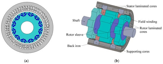
Figure 1.
Sketch of the machine geometry: (a) interior permanent magnet synchronous motor (IPMSM); (b) homopolar synchronous motor (SHM).
The stators of both machines have 54 teeth with open slots. The considered IPMSM and SHM have the same number of phases and poles and the same fundamental harmonics for power supply. The number of poles is 2p = 12, where p is the number of pole pairs in the rotor. The motors use a nine-phase two-layer winding with the number of slots per pole and phase q = 1/2. Nine phases are labeled with digits from 0 to 8 (Figure 1a and Figure 2). The “-” sign means the reverse current direction in the slot layer.
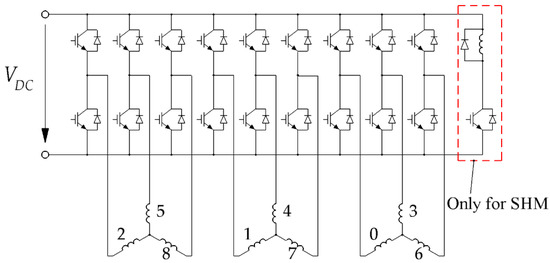
Figure 2.
Nine-phase inverter schematics. The numbers indicate the phases of the nine-phase motor.
The IPMSM rotor is made of electrical steel lamination and has V-shaped slots where rare-earth magnets are inserted (Figure 1a). Each rotor pole includes two layers of magnets.
The SHM has three sets of stacks on the stator and on the rotor. An excitation winding consisting of two coils is placed between the stator stacks. The rotor has no windings. Each rotor stack has six teeth, and the teeth of adjacent rotor stacks are offset by 30 mechanical degrees.
Figure 2 shows the inverter circuit diagram for powering the considered traction motors. The phases are grouped by three and form three three-phase windings. The considered nine-phase inverter contains three separate three-phase inverters. The SHM also requires a single chopper connected to the DC link to power the excitation winding.
Both multiphase (when the number of phases is greater than three) and multilevel topologies provide the possibility of increasing the converter power rating with a given type and a given power rating of the power switches: the first one does this by increasing the supply voltage, and the second one does this by dividing the current between the phases. The choice of the topology is determined by available power switches and supply voltage. In this study, a nine-phase inverter was chosen to reduce the current in each power module with a given supply voltage compared to the conventional three-phase inverter. This provides better reliability in the event of a partial inverter failure. In addition, the nine-phase inverter provides a better spatial spectrum of the field in the motor air gap than the multilevel invertor does. The control of the traction inverter is performed with a single microcontroller unit with 18 synchronous pulse-width modulated signals. For each three-phase section, the discontinuous space-vector modulation [24] is used.
Figure 3 shows the traction speed–torque curve of the electric drive of the BELAZ 75570 mining truck, limited by the maximum rotational speed and the maximum torque. The constant power speed range spans from 400 to 4000 rpm (1:10). The maximum mechanical power of the machine in the motor operating mode is 370 kW. Both considered motors should satisfy these characteristics.
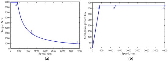
Figure 3.
Traction characteristics of the motor: (a) torque vs. rotational speed; (b) output mechanical power vs. rotational speed.
The design methods and detailed results of the SHM optimization are described in article [17]. In order not to repeat ourselves, in Section 5, we present only the final characteristics of the optimized SHM.
3. IPMSM Optimization Model
3.1. Geometry of the IPMSM
A finite element model was used to evaluate the performance of the IPMSM. Figure 4 shows the computational domain containing two poles. The Nelder–Mead algorithm used for the optimization is well known [25] and is included in the basic MATLAB software package (function “fminsearch”).
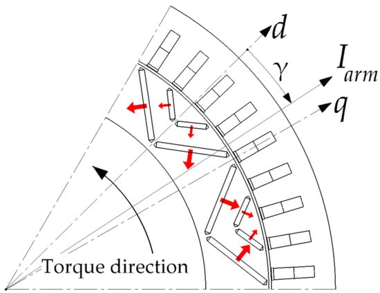
Figure 4.
Computational area of the IPMSM. Red arrows show the magnetization directions of permanent magnets.
Figure 5 shows the main dimensions of the stator and rotor of the IPMSM. The rotor has two layers of magnets at each pole pitch. To simplify the picture, only one layer is shown. The geometry of the rotor was created by the following procedure. First, point 1 is set at angle α and at distance d1 from the outer rotor boundary. D and d2 define the position of point 2. The rectangles 1234 and 1′2′3′4′ are filled with magnets and are determined with magnet thickness hmag. Point 5 is located at a distance of d1 from the outer rotor boundary. Segments 45 and 4′5′ are parallel to the middle line of the pole. Triangles 145, 1′4′5′, 236, 2′3′6′ are filled with air. Parameters d1, d2, and hmag are the same for both magnet layers. Two values of parameters D and α correspond to two layers of the rotor pole. The stator parameters Rout = 331 mm, ε1 = 1 mm and ε2 = 2 mm are not varied during optimization.
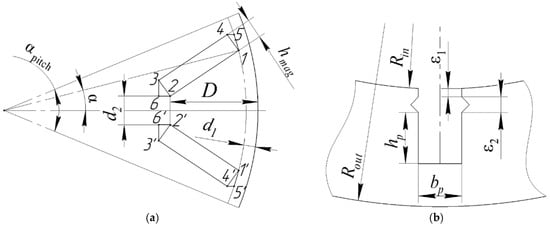
Figure 5.
Parameters of the IPMSM: (a) rotor; (b) stator.
3.2. Construction of an Objective Function for Nine-Phase Traction Synchronous Motors
Evaluating the motor performance in a particular driving cycle requires analysis at a large number of operating points, which is computationally expensive, making it difficult to optimize. One solution to reduce computational time is to introduce a substitute driving cycle profile with a small number of discrete operating points [26].
When optimizing the motor, three operating points were considered: the points with speeds of 400 rpm (maximum torque) and 4000 rpm (maximum speed), as well as the point with the geometric averages of speed and torque. These operating points are shown in Table 1 and in Figure 3.

Table 1.
Operating points of the traction motor considered during the optimization.
Points 1 and 3 are on the boundaries of the required CPSR. The performance at these boundary points is traditionally evaluated in the design of traction drives, as it can be used to approximate the performance of the drive at all operating points within the CPSR [26]. Operating point 1 is characterized by the minimum torque and maximum electric frequency of the fundamental component of the current, maximum losses in steel and additional losses in the winding due to eddy currents. Operating point 3 is characterized by the minimum electrical frequency and maximum torque and by current and ohmic losses in the winding. Since the traction drive most of the time does not operate near the boundary points, but in the inner part of the CPSR, for a more accurate assessment and better optimization of the average losses, operating point 2 is also introduced, the speed and torque of which are determined as the geometric mean of these characteristics at points 1 and 3.
It is assumed that the motor can operate with equal probability in the subranges 1–2 and 2–3. It is assumed that the average losses in the subranges are equal to the arithmetic mean of the losses at their boundaries (points 1 and 2 and points 2 and 3, respectively). Therefore, as the first optimization objective, the weighted average loss is chosen:
<Plosses> = (Plosses1 + 2 · Plosses2 + Plosses3)/4.
For comparison with the IPMSM, the SHM (Figure 1b), complying to the requirements shown in Figure 3 and powered by the inverter shown in Figure 2, has been optimized using the Nelder–Mead method to reduce power losses and the inverter-required power. The initial approximation and results of SHM optimization are presented in detail in [17].
The IPMSM design also includes the selection of winding parameters to meet the maximum voltage and current constraints. The alternator of the mining dump truck provides the DC link voltage of 1000 V, which defines the voltage limit. In addition, the IGBT module FF650R17IE4 [27] of the inverter imposes a maximum current limit of 650 A (amplitude). With some margin, the maximum current IPMSM is assumed to be 640 A.
The IPMSM optimization is carried out in two steps. At the first step, in addition to the average losses, the product of the maximum armature current max (Iarm) and the maximum DC-link voltage max (VDC) is minimized. At the second step, the number of turns is selected to meet the voltage and current constraints. In addition, the aim of both steps is to reduce the maximum relative torque ripple max (TR) as well as to control the area of the demagnetized magnets. The objective function for optimizing the IPMSM at the first stage of optimization is:
where SHmag is the area of demagnetized magnets in the computational region (two poles), and hmag is the thickness of the magnets. With an increase in the area SHmag, the last term of (2) increases rapidly. A 1% reduction in <Plosses> is as valuable as a reduction in voltage V and current I product by one third of a percent and as a reduction in maximum relative torque ripple TR by 16.7%.
F = log(<Plosses>) + 3log[max(VDC)] + 3log[max(Iarm)] + 0.06log[max(TR)] + 0.1log(Mmag)+ log [1 + 100exp(Smag/hmag2 − 0.05)],
In the second optimization step, the dimensions of the stator slot bp = 7.82 mm, hp = 25.74 mm (see Figure 5b) obtained in the first step are rounded to fit the standard rectangular wire sizes of 3 × 1.4 mm [28], which became equal to bp = 7.9 mm, hp = 26.1 mm. At the second step, the parameters bp and hp are not changed, and the objective is:
where
The weight coefficients equal to 4 for the second and third terms are large enough to meet the constraints max (VDC) < Vmax and max (Iarm) < Imax after the optimization. However, if these constraints are met, the second and third terms of the continuous function f become equal to zero. As a result, a “soft constraint” is achieved, which prevents a rapid decrease in the volume of the simplex in the space of parameters.
3.3. Optimization Parameters of IPMSM with V-Shaped Magnetic Poles
The IPMSM parameters are listed in Table 2 and Table 3 and are also shown in Figure 5 and Figure 6. Table 2 shows the parameters fixed during the optimization, and Table 3 reports the parameters varied during the optimization and their initial values. As Figure 4 shows, the current control angle γ is measured from the d-axis of the lowest reluctance toward the q-axis, which is opposite to the magnetization direction of the permanent magnets.

Table 2.
IPMSM parameters fixed during the optimization.

Table 3.
IPMSM parameters varied during the optimization.
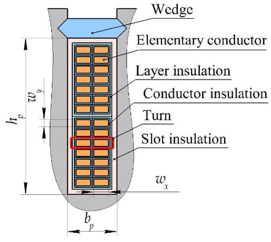
Figure 6.
Stator slot sketch.
Each winding layer contains Nsec = 7 equivalent turns. Each equivalent turn contains Nx = 2 parallel strands. Figure 6 shows the layout of a stator slot. During the optimization, it was assumed that the width of slot bp and the height of the part of the slot occupied by the winding hp are related to the wire sizes wx and wy as follows:
where ax = 1.2 mm, ay = 1.8 mm, Δw = 0.31 mm are the constants taking into account the width of the slot insulation, layer insulation, impregnation, etc.
bp = (wx + Δw) ∙ Nx + ax; hp = 2∙(wy + Δw) ∙ Nsec + ay,
Table 4 shows the results of the first step of optimization; in particular, the maximum DC-link voltage is 1097 V, which only slightly exceeds the voltage limit of 1000 V. Therefore, it was decided not to change the number of turns of the winding at the second step of the optimization.

Table 4.
Comparison of the IPMSM characteristics after different steps of the optimization.
4. Performance Comparison of the IPMSM before and after the Optimization
Table 4 shows a comparison of the IPMSM performances after different optimization steps.
Figure 7 shows the change in the geometry and the flux density plot while optimizing the IPMSM at the third operating point (400 rpm). The thickness of the stator yoke and the shape of the stator slot of the initial IPMSM design are set the same as for the optimized SHM [17]. After the first step of the optimization, the thickness of the stator yoke has significantly increased, which in the case of the IPMSM, is explained by the need to transfer the flux from pole to pole through the yoke. In SHM, the yoke has only the function of distributing the flux before entering the motor housing; thus, it is narrower than that of the IPMSM. The height of the slot decreased significantly, while the width of the slot did not decrease as much. This can be explained by the fact that in order to create the reluctance torque, it is necessary to increase the anisotropy of magnetic conductivity and, in particular, to reduce the parasitic slot leakage flux.
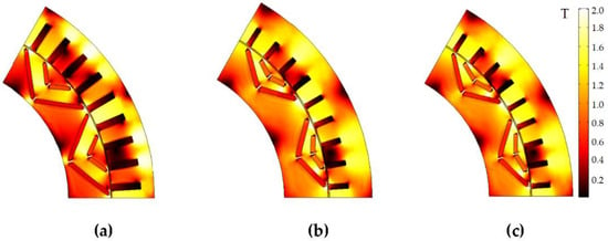
Figure 7.
Modification of the geometry and magnitude of the flux density in the IPMSM during the optimization: (a) initial design; (b) result of the 1st step; (c) final result.
At the second optimization step, the IPMSM geometry remained practically unchanged, since at this step, the design was adapted to the current and voltage constraints and to the standard wire size.
As noted above, both the voltage and the current are the constraints in optimizing the IPMSM. To comply with the current constraint at operating points 2 (1265 rpm) and 3 (400 rpm), the current angle is set close to the MTPA (maximum torque per ampere) curve. In this case, the current vector does not coincide with the d-axis, and the current angle is slightly more than 50 el. degrees at operating point 3 (see Table 3), which indicates the presence of not only the torque created by the permanent magnets, but also the reluctance torque.
As the rotational speed increases, the voltage constraint becomes important for the IPMSM as the back-EMF (electromotive force) and winding reactance increases as well. These components of the motor impedance begin to dominate above the voltage drop across the stator resistance and inverter supply voltage and establish a voltage-independent current. According to Lenz’s law, this current is opposite to the direction of magnetization of the magnets, i.e., it is directed along the q-axis and can interact with the co-directional voltage, transferring electrical power. Therefore, the current control angle at operating point 1 (4000 rpm) is close to zero el. degrees (see Table 3). Operating point 2 occupies an intermediate position between points 1 and 3. At point 2, a strong field weakening is not required, although the current control angle is slightly smaller than at point 1, which indicates some increase in field weakening.
Thus, with an increase in the rotational speed for the IPMSM, the armature current first decreases and then increases to a value close to the asymptotic value (to the short-circuit current). This leads to high losses in copper and steel at high speeds. Apparently, if a wide CPSR is required, IPMSMs are characterized by the presence of a range of speeds, in which the current increases with increasing rotational speed. If the required CPSR is narrower, then such a range may not be present.
5. Performance Comparison of the Optimized SHM and IPMSM
This section discusses the comparison of the characteristics of the considered electrical machines after optimization. Table 5 and Figure 8 show performance comparison between the optimized IPMSM and SHM. The mechanical losses in the IPMSM including friction and ventilation losses are assumed to be the same as for the SHM. The losses in magnets from higher harmonics in IPMSM were neglected since they are small. Table 6 compares the weight and size characteristics and the cost of active materials for the optimized IPMSM and SHM.

Table 5.
Performance comparison of IPMSM and SHM after the optimization.
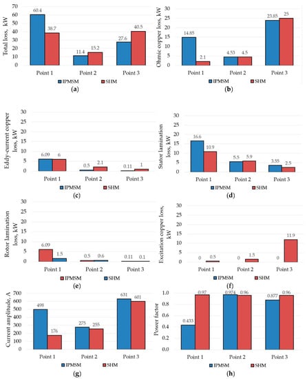
Figure 8.
Performance comparison of IPMSM and SHM after the optimization for different operating points: (a) total loss; (b) armature ohmic copper loss; (c) armature eddy-current copper loss; (d) stator lamination loss; (e) rotor lamination loss; (f) excitation copper loss, kW; (g) amplitude of the armature phase current; (h) power factor.

Table 6.
Comparison of calculated characteristics of the IPMSM and SHM after the optimization.
We would like to highlight a few points that can be made by comparing the characteristics of the IPMSM and SHM shown in Table 5 and Table 6.
(1) In the case of a wide CPSR, if the current angle is controlled to obtain the maximum motor efficiency, which corresponds to the MTPA strategy, then supply voltage will significantly exceed its limit at high speed. Therefore, at high speed (in this calculation, this is operating point 1 at 4000 rpm), the field weakening strategy must be applied.
Although field weakening at high speeds, which is obtained by increasing the demagnetizing stator winding current, is part of the control strategy for the SHM as well, the optimization results show that an additional reduction in the excitation current is also required. Thus, in the case of the SHM, both the armature current and the excitation current decrease with increasing the speed.
In the case of IPMSM, in which the MMF of the permanent magnets cannot be controlled, the q-axis armature current component is increased to implement field weakening in order to create an MMF opposite to the MMF of the permanent magnets. The application of the field weakening strategy leads to the fact that the armature current of the IPMSM at operating point 1 at 4000 rpm is significantly greater than at operating point 2 at 1265 rpm. The IPMSM power factor at 4000 rpm is even less than 0.5, which, however, does not violate the current and voltage constraints and does not increase the required inverter power. In addition, the high-speed losses for the IPMSM are more than 60 kW, which is significantly higher than for the SHM (38.7 kW), which can lead to overheating of the IPMSM at this operating point.
(2) The IPMSM motor contains expensive rare-earth magnets designed to operate at high temperatures. As a result, Table 6 shows that the total cost of active materials in IPMSM (USD 5351.2) is 4.6 times higher than the cost of materials in SHM (USD 1167).
(3) Without taking into account the length of the winding end parts, the IPMSM takes about 30% less length than the SHM, which is an advantage of the IPMSM. The outer diameter of the stator laminations for the IPMSM and SHM is the same.
(4) The SHM will be more reliable than the IPMSM, as there is no risk of overheating, demagnetization or degradation of permanent magnets over time. In addition, since the motor in the considered application has an open-type air-cooled housing, when using the IPMSM, there is also risk of damage to the protective coating and subsequent corrosion of permanent magnets. The ore dust from the mining area can be stuck to the rotor being magnetized by permanent magnets, which may damage the motor as well. In the SHM, as it has no magnets, such risk is absent [30]. The ore dust from the mining area can be stuck to the rotor being magnetized by permanent magnets, which may damage the motor as well.
6. Conclusions
This study compares the performance of the IPMSM and SHM for the drive of the mining dump truck with a mechanical power of 370 kW and a CPSR of 1:10. For this purpose, both motor designs are pre-optimized using the same technique. The analysis is based on the two-dimensional planar finite element method and on the simplex gradient-free Nelder–Mead optimization method.
The main objectives of optimization are to minimize the average losses in the operating cycle and to limit the required power of the semiconductor inverter (maximum inverter current and maximum DC link voltage). Torque ripple, permanent magnet mass, and demagnetized permanent magnet area are also included into the objective function in order to limit these values. The IPMSM characteristics obtained as a result of the optimization are compared with the SHM characteristics obtained by the authors in their previous study using a similar technique.
Although the average losses in the operating cycle turned out to be approximately equal in the compared motors, however, due to the need for a strong field weakening, the loss at high speed for IPMSM is about two times greater than at low speed with maximum torque, which indicates the need to intensify the IPMSM cooling system. This also means less reliability. At the same time, for the SHM, the loss at high speed does not exceed the loss at the operating point with low speed and maximum torque.
The advantage of the IPMSM is the reduction in the length of the active part by 30%. The advantage of the SHM is a 4.6-times lower cost of active materials. In addition, the SHM will be more reliable than IPMSM, as there is no risk of overheating, demagnetization, or degradation of permanent magnets over time, including other risks related to the use of permanent magnets.
Author Contributions
Conceptual approach, A.A., V.D. and V.P.; data duration, V.D. and V.K.; software, V.D. and V.P.; calculations and modeling, A.A., V.D., V.K. and V.P.; writing—original draft, A.A., V.D., V.K. and V.P.; visualization, V.D. and V.K.; review and editing, A.A., V.D., V.K. and V.P. All authors have read and agreed to the published version of the manuscript.
Funding
The research was performed with the support of the Russian Science Foundation grant (project № 21-19-00696).
Institutional Review Board Statement
Not applicable.
Informed Consent Statement
Not applicable.
Data Availability Statement
Data are contained within the article.
Acknowledgments
The authors thank anonymous for careful reading and constructive comments.
Conflicts of Interest
The authors declare no conflict of interest.
References
- Credo, A.; Fabri, G.; Villani, M.; Popescu, M. High Speed Synchronous Reluctance Motors for Electric Vehicles: A Focus on Rotor Mechanical Design. In Proceedings of the 2019 IEEE International Electric Machines & Drives Conference (IEMDC), San Diego, CA, USA, 12–15 May 2019; pp. 165–171. [Google Scholar]
- Dianov, A.; Tinazzi, F.; Calligaro, S.; Bolognani, S. Review and Classification of MTPA Control Algorithms for Synchronous Motors. IEEE Trans. Power Electron. 2022, 37, 3990–4007. [Google Scholar] [CrossRef]
- Soong, W.L.; Ertugrul, N. Field-weakening performance of interior permanent-magnet motors. IEEE Trans. Ind. Appl. 2002, 38, 1251–1258. [Google Scholar] [CrossRef]
- Chen, H.; Lee, C.H.T. Parametric Sensitivity Analysis and Design Optimization of an Interior Permanent Magnet Synchronous Motor. IEEE Access 2019, 7, 159918–159929. [Google Scholar] [CrossRef]
- Dianov, A. Optimized Field-Weakening Strategy for Control of PM Synchronous Motors. In Proceedings of the 2022 29th International Workshop on Electric Drives: Advances in Power Electronics for Electric Drives (IWED), Moscow, Russia, 26–29 January 2022; pp. 1–6. [Google Scholar] [CrossRef]
- Pellegrino, G.; Vagati, A.; Boazzo, B.; Guglielmi, P. Comparison of Induction and PM Synchronous Motor Drives for EV Application Including Design Examples. IEEE Trans. Ind. Appl. 2012, 48, 2322–2332. [Google Scholar] [CrossRef]
- Papini, F.; Osama, M. Electromagnetic Design of an Interior Permanent Magnet Motor for Vehicle Traction. In Proceedings of the 2018 XIII International Conference on Electrical Machines (ICEM), Alexandroupoli, Greece, 3–6 September 2018; pp. 205–211. [Google Scholar] [CrossRef]
- The First-Ever BMW iX3, Highlights, PressClub Global, Article. Available online: https://www.press.bmwgroup.com/global/article/detail/T0310696EN/the-first-ever-bmw-ix3?language=enhttps://www.netcarshow.com/bmw/2021-ix3 (accessed on 7 April 2022).
- Feustel, S.; Huebner, B.; Loos, D.; Merwerth, J.; Tremaudant, Y.; Vollmer, K. Rotor for Separately Excited Inner Rotor Synchronous Machine, Inner Rotor Synchronous Machine, Motor Vehicle and Method. U.S. Patent US20210006105A1, 7 January 2021. Available online: https://patents.google.com/patent/US20210006105A1 (accessed on 7 April 2022).
- Raia, M.R.; Ruba, M.; Martis, C.; Husar, C.; Sirbu, G.M. Battery electric vehicle (BEV) powertrain modelling and testing for real-time control prototyping platform integration. In Proceedings of the 2021 23rd European Conference on Power Electronics and Applications (EPE’21 ECCE Europe), Ghent, Belgium, 6–10 September 2021; pp. 1–10. Available online: https://ieeexplore.ieee.org/document/9570616 (accessed on 7 April 2022).
- Tran, T.-V.; Nègre, E. Efficient Estimator of Rotor Temperature Designing for Electric and Hybrid Powertrain Platform. Electronics 2020, 9, 1096. [Google Scholar] [CrossRef]
- Zhu, Z.Q.; Chu, W.Q.; Guan, Y. Quantitative comparison of electromagnetic performance of electrical machines for HEVs/EVs. CES Trans. Electr. Mach. Syst. 2017, 1, 37–47. [Google Scholar] [CrossRef]
- Bindu, G.; Basheer, J.; Venugopal, A. Analysis and control of rotor eccentricity in a train-lighting alternator. In Proceedings of the 2017 IEEE International Conference on Power, Control, Signals and Instrumentation Engineering (ICPCSI), Chennai, India, 21–22 September 2017; pp. 2021–2025. [Google Scholar] [CrossRef]
- Orlova, S.; Pugachov, V.; Levin, N. Hybrid Excitation of the Axial Inductor Machine. Latv. J. Phys. Tech. Sci. 2012, 49, 35–41. [Google Scholar] [CrossRef][Green Version]
- Lorilla, L.; Keim, T.; Lang, J.; Perreault, D. Topologies for future automotive generators. Part I. Modeling and analytics. In Proceedings of the 2005 IEEE Vehicle Power and Propulsion Conference, Chicago, IL, USA, 7 September 2005; pp. 74–85. [Google Scholar]
- Bianchini, C.; Immovilli, F.; Bellini, A.; Lorenzani, E.; Concari, C.; Scolari, M. Homopolar generators: An overview. In Proceedings of the 2011 IEEE Energy Conversion Congress and Exposition, Phoenix, AZ, USA, 17–22 September 2011; pp. 1523–1527. [Google Scholar] [CrossRef]
- Prakht, V.; Dmitrievskii, V.; Anuchin, A.; Kazakbaev, V. Inverter Volt-Ampere Capacity Reduction by Optimization of the Traction Synchronous Homopolar Motor. Mathematics 2021, 9, 2859. [Google Scholar] [CrossRef]
- Lee, S.-H.; Hong, J.-P.; Kwon, Y.-K.; Jo, Y.-S.; Baik, S.-K. Study on homopolar superconductivity synchronous motors for ship propulsion applications. IEEE Trans. Appl. Supercond. 2008, 18, 717–720. [Google Scholar] [CrossRef]
- Sugitani, N.; Chiba, A.; Fukao, T. Characteristics of a doubly salient-pole homopolar machine in a constant-power speed range. In Proceedings of the 1998 IEEE Industry Applications Conference. Thirty-Third IAS Annual Meeting (Cat. No.98CH36242), St. Louis, MO, USA, 12–15 October 1998; pp. 663–670. [Google Scholar] [CrossRef]
- Lashkevich, M.; Anuchin, A.; Aliamkin, D.; Briz, F. Control strategy for synchronous homopolar motor in traction applications. In Proceedings of the 43rd Annual Conference of the IEEE Industrial Electronics Society (IECON), Beijing, China, 29 October–1 November 2017; pp. 6607–6611. [Google Scholar] [CrossRef]
- Li, Y.; Yang, H.; Lin, H.; Fang, S.; Wang, W. A Novel Magnet-Axis-Shifted Hybrid Permanent Magnet Machine for Electric Vehicle Applications. Energies 2019, 12, 641. [Google Scholar] [CrossRef]
- Wang, Y.; Bianchi, N.; Qu, R. Comparative Study of Non-Rare-Earth and Rare-Earth PM Motors for EV Applications. Energies 2022, 15, 2711. [Google Scholar] [CrossRef]
- Goss, J.; Popescu, M.; Staton, D. A comparison of an interior permanent magnet and copper rotor induction motor in a hybrid electric vehicle application. In Proceedings of the 2013 International Electric Machines & Drives Conference, Chicago, IL, USA, 12–15 May 2013; pp. 220–225. [Google Scholar] [CrossRef]
- Anuchin, A.; Aliamkin, D.; Lashkevich, M.; Shpak, D.; Zharkov, A.; Briz, F. Minimization and redistribution of switching losses using predictive PWM strategy in a voltage source inverter. In Proceedings of the 2018 25th International Workshop on Electric Drives: Optimization in Control of Electric Drives (IWED), Moscow, Russia, 31 January–2 February 2018; pp. 1–6. [Google Scholar] [CrossRef]
- Nelder, J.; Mead, R. A Simplex Method for Function Minimization. Comput. J. 1965, 7, 308–313. [Google Scholar] [CrossRef]
- Guo, S.; Zhao, H.; Wang, Y.; Yin, X.; Qi, H.; Li, P.; Lin, Z. A Design Technique of Traction Motor for Efficiency Improvement Based on Multiobjective Optimization. World Electr. Veh. J. 2021, 12, 260. [Google Scholar] [CrossRef]
- FF650R17IE4, IGBT-Modules, Technical Information, Revision 3.3, Infineon. November 2013. Available online: https://www.infineon.com/dgdl/Infineon-FF650R17IE4-DS-v03_03-EN.pdf?fileId=db3a30431ff9881501201dcfe2a54986 (accessed on 7 April 2022).
- IEC. Specifications for Particular Types of Winding Wires—Part 0-2: General Requirements—Enamelled Rectangular Copper Wire; IEC 60317-0-2:2020; IEC: Geneva, Switzerland, 2020; Available online: https://webstore.iec.ch/publication/63495 (accessed on 7 April 2022).
- ChenYang NdFeB Magnets. Price List of Standard Block Magnets. Available online: http://www.ndfebmagnets.de/CY-PriceList-NdFeB-Block.pdf (accessed on 2 May 2022).
- Kramer, M.; McCallum, R.; Anderson, I.; Constantinides, S. Prospects for Non-Rare Earth Permanent Magnets for Traction Motors and Generators. JOM 2012, 64, 752–763. [Google Scholar] [CrossRef]
Publisher’s Note: MDPI stays neutral with regard to jurisdictional claims in published maps and institutional affiliations. |
© 2022 by the authors. Licensee MDPI, Basel, Switzerland. This article is an open access article distributed under the terms and conditions of the Creative Commons Attribution (CC BY) license (https://creativecommons.org/licenses/by/4.0/).