Abstract
According to the statistics provided by the World Health Organization, the number of people suffering from visual impairment is approximately 1.3 billion. The number of blind and visually impaired people is expected to increase over the coming years, and it is estimated to triple by the end of 2050 which is quite alarming. Keeping the needs and problems faced by the visually impaired people in mind, we have come up with a technological solution that is a “Smart Cane device” that can help people having sight impairment to navigate with ease and to avoid the risk factors surrounding them. Currently, the three main options available for blind people are using a white cane, technological tools and guide dogs. The solution that has been proposed in this article is using various technological tools to come up with a smart solution to the problem to facilitate the users’ life. The designed system mainly aims to facilitate indoor navigation using cloud computing and Internet of things (IoT) wireless scanners. The goal of developing the Smart Cane can be achieved by integrating various hardware and software systems. The proposed solution of a Smart Cane device aims to provide smooth displacement for the visually impaired people from one place to another and to provide them with a tool that can help them to communicate with their surrounding environment.
1. Introduction
According to the World Health Organization, 1.3 billion people live with some form of visual impairment [1]. While the prevalence of blindness has declined since 1990, the aging of the population will in the future lead to a much larger number of blinds and partially sighted [2]. In fact, the number of blinds in the world is expected to triple by 2050 [3], increasing from 39 million now to 115 million. This increasing number has motivated our work to design an autonomous cane to facilitate the navigation of blind people in unknown environment.
To assist the blind in their displacement, we mainly count the white cane, guide dog and technological tools. The white cane remains the most widely used mobility aid. It allows the detection of obstacles with a range of three feet. This reduced range forces the user to be ready to stop or correct his trajectory quickly, and therefore limits the speed of operation [4]. While it cannot warn of the presence of hanging objects such as tree branches; it is easily recognizable by other pedestrians, warning passers-by to stay out of the way, but also marginalize the blind [4]. Despite its flaws, the long cane is a wonderful instrument, providing surprisingly rich information. It is mainly used to make arches, tapping at each end [5]. The sounds emitted by the tapping can be used for echolocation. Dynamic contacts also inform about the texture and slope of the terrain. All this and “the signals given by the soles of the feet” are rich sources of information to help blinds. The dog for the blind is also a popular aid with around 7000 users. Dogs for the blind are effective and can be trained by professionals and maintained by their owners. Their cost varies from twelve to twenty thousand dollars. Their professional life is about five years.
Technological tools aiming for assisting blind are known as electronic travel aids (EDAs). EADs can be divided into two categories, depending on their main use. The first category helps the blind to orient themselves in their environment while traveling to a given destination. The second category provides warning for the presence of obstacles and facilitates the selection of a path without pitfalls. Our proposal is about this second category. It is a stick equipped with several sensors aiming to facilitate indoor navigation. An analysis of existing technologies shows that the research has largely focused on outdoor navigation; the GPS (Global Positioning System) being the main sensor used for this purpose [6]. Our interest is in indoor navigation.
Indoor navigation remains an active research area [7,8,9]. The idea is to be able to help people navigate towards an indoor point of interest. This is generally considered a challenging task; especially for people who are visually impaired or blind. This group may indeed have considerable problems when trying to navigate through an unfamiliar place (e.g., a university, a shopping mall, or public buildings such as courthouses).
We report here the design of a smart and autonomous cane. The proposed system is designed to be easy to use. Using a computer vision system, object detection is provided. This allows the blind persons to safely navigate through many obstacles. Cloud services use modern algorithms to rapidly calculate the distance of detected objects. This fast calculation of the path is very useful for the user as it enables the real time navigation. Moreover, since it vocalizes the elements encountered in the environment, it allows the blind person to search for any particular object in the surrounding environment.
Figure 1 shows a graphical representation of a smart autonomous cane with object detection and a navigation system. It has an object detector at the lower end and a navigation system with audio device at the upper end where the user can interact with it using his/her hand.
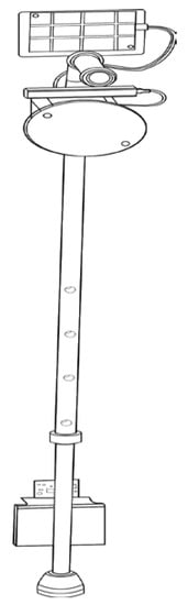
Figure 1.
Smart Cane.
The rest of the paper is organized as follows. Section 2 reviews the current literature about the indoor navigation systems including techniques and principles used for performing tasks that a Smart Cane is expected to perform. Section 3 presents the proposed system including the characteristics of the system, triangulation principle, object detection and route determining. Section 4 presents the experimental setup where the system is tested and then reports the system performance. Finally, Section 5 concludes the paper and gives future directions.
2. Related Study
In the last two decades, many technologies have been proposed in order to assist blinds or visually impaired persons to navigate in closed spaces. We divide this section into three main areas. Many research projects have been carried out in the field of indoor positioning technologies [10,11]. To achieve this, different techniques for locating an object were investigated. Here, we briefly analyze the main indoor location methods.
The Laterartion method assesses the distance of an object by measuring the distance of the object from different reference points; these techniques are known as range measurement techniques. Time distance of arrival (TDOA) is a kind of Laterartion technique that has been used to measure indoor position of an object with respect to signal with three reference points [12,13]. Authors of [14,15] have proposed the method to measure TDOA using different signaling techniques, i.e., ultra-wide band measurements (UWB) and direct-sequence spread-spectrum (DSS) [16]. Others [17,18] have proposed a non-linear cost function for measuring the indoor location of an object, where the cost function computes the location by minimizing the sum of squares of non-linear cost function, e.g., least-square algorithms.
Some other algorithms for measuring indoor position of an object are residual weighting, closest neighbor (CN) that assesses the location with respect to the reference points or location of the base stations [18]. These TDOA based methods have some drawbacks when it comes to indoor environments, it becomes difficult to find LOS channel between the receiver and the transmitter. This shortcoming can be value-added by applying the premeasured RSS (Received Signal Strength) contours at the receiver side or at the base stations [19]. Authors in [20] proposed a fuzzy logic algorithm for improving the accuracy using the RSS method considerably.
Another method based on received signal phase assesses the range using carrier phase, also known as phase of arrival (POA). This method assumes the transmitting stations having same frequency and zero offset for determining the sinusoidal signals phase at a point [21]. This method can be used in combination of TDOA for fine-tuning the location positioning, but the problems come with the ambiguous measurements of the carrier phase, LOS signal path resolves this issue otherwise the indoor positioning environment incurs more error.
In this respect, authors have also focused on angulation techniques that find the target in an indoor environment using the intersection of several points in angle direction lines. These techniques are advantageous where the users are required to estimate positions for 2-D and 3-D environments and they also do not require time synchronization among measuring units. On the other hand, they have complex hardware requirements [22,23]. Another technique that cogitates position as a classification problem is probabilistic method. These probabilistic methods work upon calculating the likelihood of independent measuring units, i.e., the Kernel approach and the histogram. The likelihood of one-unit location can be calculated by multiplying likelihoods of all units [24]. These methods work accurately only for discrete locations as mobile units are usually located at different points rather than the discrete points. Researchers also have investigated other indoor location-aware methods like Bayesian network-based methods and tracking assisted positioning methods are proposed in [25].
New techniques for indoor positioning findings are based on supervised or machine learning algorithms. One of them is support vector machines (SVM) extensively used in applications like medicine, engineering and science [26]. Researchers have focused on support vector classification and support vector regression in indoor positioning environments [27,28]. SMP (Smallest M-vertex Polygon) has also been studied in location estimation that uses RSS values for finding location of the target with the reference of transmitter signal. M-vertex polygons are created by selecting one candidate from the transmitter where the smallest polygon suggests the location estimation [24]. Other machine learning/supervised learning algorithms that are under consideration for estimating location in an indoor environment are KNN and neural networks. K-nearest neighbor algorithm works on online RSS for searching k nearest matches of recognized places from already created database using root mean square error principle. The estimated location is found (weighted/un-weighted KNN) by averaging the k location candidates. On the other hand, neural networks are used during the offline RSS stage. The appropriate weights are gained by training neural networks, in the indoor positioning environments, a multilayer perceptron (MLP) network with one hidden layer is used. Neural networks, in indoor positioning environments, are capable of finding 2D or 3D estimated locations.
Other techniques for finding target location of an object in an indoor positioning environment are Proximity-based methods. These algorithms deliver symbolic relative information, depending upon dense grid antennas with a popular location with each antenna. When single antenna detects the target, it is reflected to be collocated with it, when detected by more than one antenna, it is collocated with the strongest signal antenna. Proximity-based techniques are easier and simple to implement for detecting target location in an indoor environment over various kinds of physical media. Systems using radio frequency identification (RFID) and infrared radiation (IR) are making use of proximity-based methods.
Laser and camera-based indoor positioning system has also been developed by Tilch and Mautz [9], to define the camera position with reference to the laser ring. As the ring emits laser-beams, it can be observed as an inverse camera. The comparative orientation between laser rig and camera can be calculated with the help of laser spots that are projected to any surface irrespective of a defined structure of a scene. With this laser and camera-based positioning system, the point tracking is obtained at the frame rate of 15 Hz while the camera accuracy is sub-mm.
Another indoor localization system known as NorthStar has been developed by evolution robotics [29] that navigates robot vacuum cleaners and shopping carts. Here, infrared light spots that are emitted from infrared LED specify the location of the mobile units. In NorthStar, every mobile unit is equipped with a projector and an infrared detector for determining the relative orientation between mobile devices. The positioning accuracy is reported to be in the magnitude of cm to dm.
Other techniques for object detection in an indoor positioning environment rely on reference from 3D building models, that depend on detecting objects in images and then matching these with a built database, i.e., CityGML contains position data of the interior of building. These methods have advantageous, as there is no need to deploy sensor beacons [30,31]. In this regard, important research has been conducted by Kohoutek et al. [10], using CityGML as highest level of detail for determining position of imagining camera within the range. Initially, the correct room with camera is located using the CityGML database. Then the indoor objects with like doors and windows are spotted using 3D point cloud obtained by range image sensor. In the final step, dm-level fine positioning of the camera-based method combines spatial and trilateration resection.
Muffert et al. [32], specify the trajectory of an omnidirectional video camera based on relative orientation of consecutive images. The path drifts away from the trajectory when there is no control over reference directions. A low-cost indoor positioning system for off-the-shelf camera phones has also been developed by Mulloni et al. [11], using bar-coded fiduciary markers. The markers are positioned on certain objects like walls or posters etc. Further, 6-DOF (degrees of freedom) tracking can deliver centimeter-level accuracy when markers are tracked.
Previously Proposed Smart Cane
Smart Cane serves as an enhancement to the visual impairment devices by detecting knee-above and hanging obstacles. These obstacles can be the strings of hanging clothes, the corner or edge of a truck or inclined ladders, etc. These obstacles can result in injury to the head or upper body parts as they do not possess any footprint on the ground. It also detects the presence of the objects in surroundings using vibratory patterns [33].
Different sensors are embedded in the Smart Cane. They are the ultrasonic sensors that are used to first detect and avoid the obstacles in front of a person. At the same time there is a fuzzy controller that is aimed to instruct the person, i.e., to turn to right, left or to stop [34,35]. In [36], the ultrasonic sensor is coupled to a GPS. A vibration actuator is used to convey distance of obstacles. Each distance corresponds to a certain delay among the vibrations where greater distance has greater delays. Another model described in [37] uses radio frequency identification (RFID). RFID detects objects or obstacles which come in the track of the persons. RFID is also able to detect the RFID tags which have been placed in several areas for navigating persons.
With this brief review, we noticed that Smart Cane can be used by everyone having any visual impairment. Independent travelers can use this device for their mobility. People who commute long-distance walking are usually the ones who can get the most out of it. The people having a non-acceptance view of their disability will be less eager to use the Smart Cane. This can be observed among the people who are adolescents and are highly skeptical of how they would be perceived by peers. As a result, it appears that Smart Cane is very useful and simple to use with exciting features like:
- Ergonomic grip for comfortable holding and cane tapping: Smart Cane provides different gripping styles that allow users to use their natural way of holding cane.
- Built-in rechargeable battery with a long battery back-up: Smart Cane is easily charge-able like a mobile phone. The removal of the battery is not required for/while charging the device.
- Fully accessible user interface: the interface is very friendly where there is varying number of beeps for conveying different messages, i.e., battery low or status of the charging, etc.
- Vibrations are uniformly produced on the entire grip: The Smart Cane provides non-localized vibration feedback for allowing users to grasp/hold the device conveniently.
- Easy attachment/detachment from a white cane: the white cane can easily be replaced by the user himself.
The proposed Smart Cane is one of its kind state-of-the-art device with unmatchable usability features. It uses advanced IoT wireless scanner and other navigation instruments that perform well in all conditions. Cloud connectivity with backend database system makes it stands out as compared to other competitors. The next section includes all the description of the Smart Cane indoor navigation system with in-depth details of each component used.
3. Proposed Smart Cane Indoor Navigation System
3.1. Identification of Users’ Requirements
Identification of user requirements is the basic and essential part of a system. According to Mitchell David Kapor, “design is where you stand with two worlds—the world of technology and the world of people—and you try to bring the two together.” From this point of view, we want to understand how current technology could help improve the independence of visually impaired people. Considering the tools that have proved their worth in this field as mentioned above, the white cane and the guide dog appear at the head of the list. A quick analysis of these assistive systems shows that they mainly offer:
- Help to achieve autonomous navigation;
- Provide safety and comfort in the displacement;
- Provide a companion and a significant vector of communication;
- Help to pick up a fallen object.
It is important to note that these four features are not covered completely by neither the white cane nor the guide dog. To achieve a high-quality system that will meet the needs and lifestyle requirements of blind people, we focus on identifying the needs that the ideal assistive tool should fulfil. Doing so, we have identified main characteristics that an assistive device for blind or visually impaired people should offer:
- Assist visually impaired people to come to autonomous navigation;
- Providing security and comfort while moving from one place to another;
- Offering a tool that will support them to communication with others;
- Offering a tool that will identify objects within the surrounding environment.
3.2. Main Characteristics of the Proposed System
As discussed in the previous subsection, the proposed system has been designed to offer great usability to its users. Usability can be defined as “the measure of user performances in the context of intended use”. Usability can be measured by various indicators such as ease of learning, ease of memorization, error-free use, and so on. That is why the proposed system is centered on providing all possible help with a smart white cane. Figure 2 shows an indoor navigation system that uses cloud computing and IoT concepts to assist the users with the Smart Cane. Smart Cane has the ability to collect the data that is transmitted to cloud network. Moreover, IoT wireless scanner is also connected to cloud computing that makes a complete indoor navigation system that is further explained in the next sections.
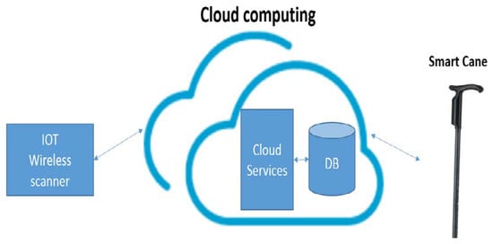
Figure 2.
Smart Cane indoor navigation system.
The proposed Smart Cane indoor navigation system including all the software and hardware components is discussed in detail in the following sections.
3.3. Detailed Explanation of Proposed System Components
Visually impaired persons including deaf-blind, blind, and low vision people require assistance in their daily life. Navigating complex routes and finding objects of interest are challenging tasks for visually impaired persons and in today’s world, there is a lack of infrastructures to make it easier. One of the most problematic tasks for visually impaired people is outdoor navigation [38]. Here, this element is typically termed as macro-navigation or orientation. It includes multiple sub-processes such as being oriented, selecting an appropriate path, maintaining the path, and detecting when the destination has been reached. These tasks are dedicated to processing the remote environment, beyond the immediate perceptible ones. In the case of visual impairment, the main cues (e.g., landmarks and paths) for sensing the environment are degraded. This results in difficulties relating to correct orientation or heading, piloting (i.e., guidance from place to place using landmarks) and retaining the path, etc. A system that assists visually impaired persons’ navigation and orientation in real time will be of great benefit to achieve this demanding task.
Our proposed system is made up of an ultrasonic sensor that was interfaced to the microcontroller, codes were written with the Arduino sketch and the physical sensor was connected to the microcontroller. The system will allow the blind to freely navigate to their desired destination. It is also user-friendly and easy. It is affordable and therefore can be mass produced for use of the visually impaired. The system has the capacity to detect obstacles that exist on the ground during walks of indoor and navigation. A camera mounted on the Smart Cane can detect objects and colors and relay the information to the user via an audio message, this means that the users can independently locate objects around them, also with accelerometer we count the number of steps and calculate the number of calories burns to encourage users who have lung disease to move.
The Smart Cane is basically an embedded system integrating the following: pair of ultrasonic sensors to detect obstacles in front of the blind from ground level height to head level height in the range of 400 cm ahead. Ultrasonic sensors and connected to a cloud service for easy navigation. Using this Arduino Smart Cane, a visually impaired person can walk without anyone’s help. The cane can automatically detect an obstacle and give the user a feedback response by giving a warning sound.
Cloud services: this gets the position of the cane, gets the route to destination and gets the traffic to the destination. The data comes from the Wi-Fi Arduino board from the last stage to the cloud service. The cloud service then uses a Gaussian model for the triangular based pose estimation. This code we use is an open source code for the resection problem, it gives us the position of the cane at that point. The cloud service is linked to the database which has all the paths. The cloud service then gets the path, i.e., the shortest and the safest path considering the traffic. The cloud service also gets traffic. These are the number of devices that can be connected. It outputs three lights. Red when devices are greater than 15, yellow if the devices are between 5 and 15 and green if the devices are less than 5.
IoT wireless scanner: The wireless scanner sends the cloud names and the received signal strength indicator (RSSI) of Wi-Fi and Bluetooth devices scanned as shown in Figure 3. It is built using aHM-10 Bluetooth RSSI or received signal strength indicator. RSSI is typically used to estimate the distances [2]. Generating, detecting and processing ultrasonic signals in ultrasonic is the production of sound waves above the frequency of human hearing and can be used in a variety of applications such as sonic rulers, proximity detectors, movement detectors, liquid level measurement. The distance between the sender and the receiver machines has an impact on the signal strength this is then used to calculate the distance. The distance of the obstacle is determined based on the delay between the emission of sound and the arrival of an echo. The distance of the obstacle can be measured as distance = (time × speed of sound in air)/2, [3]; where time is the time duration for which the ultrasonic waves have travelled and speed of sound in air is 340 m/s. The advantage of this is that it is a cheap solution for distance estimation. The Arduino component, on the other hand, gives an easy path to use the device for communication between the cloud and the wireless scanner.
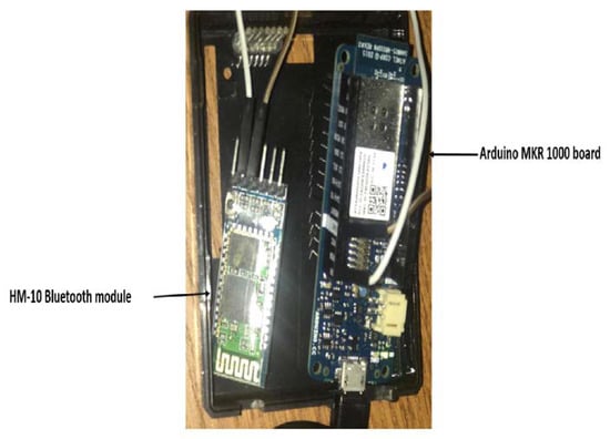
Figure 3.
IoT wireless scanner.
Smart Cane: Created with ultrasonic sensor distance measuring module, keyboard for blind people, accelerometer, ESP32 board, Pixy cam, and Emic 2 Text-to-Speech module as shown in Figure 4. The ultrasonic sensor distance measuring module includes ultrasonic transmitters, receiver and control circuit. The ultrasonic sensors send a sequence of ultrasonic pulses. If the obstacle is detected, then the sound will be reflected back to the receiver [39]. The microcontroller processes the readings of the ultrasonic sensors in order to activate the motors by sending pulse width modulation. It also provides a low power consumption. The data from this sensor is sent to the ESP32 board for transmission to the cloud. The keyboard for blind people is used as an input device. The blind person touch types their destinations and then the path is calculated. An accelerometer is one of the most important things in the stick. Accelerometers get the acceleration forces electromagnetically. Now they are used to detect and measure the gravitational and other forces. They are used to measure the speeds with which a person is traveling. Now this speed is important when it comes to the path updating to the user.
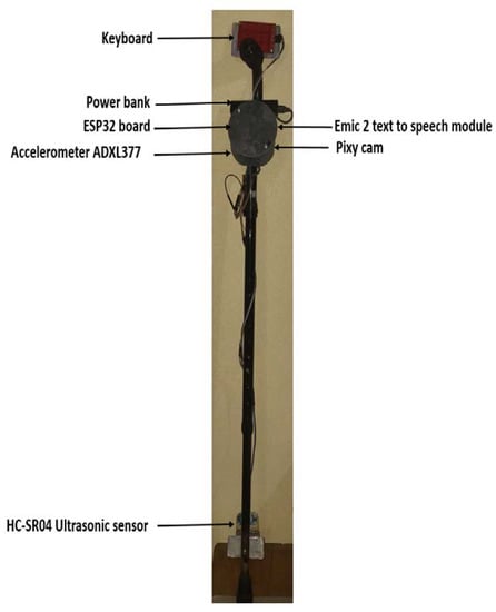
Figure 4.
The components of the Smart Cane.
The Smart Cane is composed of:
Ultrasonic sensor distance measuring module for the detection of an obstacle. The HC-SR04 Ultra01 + Ultrasonic Range Finder provides 2–400 cm non-contact measurement function, the ranging accuracy can reach to 3 mm. The module includes ultrasonic transmitters, receiver, and control circuit [40].
Keyboard for blind people.
Accelerometer—we use the accelerometer to know the position of cane and calculate a number of steps. Here, we are using the ADXL337 and the ADXL377 are both small, thin, low power, complete 3-axis accelerometers with signal conditioned analog voltage outputs [41].
ESP32 board—send data of sensor to the cloud and receive data from the cloud like route and obstacle position and traffic. ESP32 is a series of the low-cost, low-power system on a chip microcontroller with integrated Wi-Fi and dual-mode Bluetooth. The ESP32 series employs a Tensilica Xtensa LX6 microprocessor in both dual-core and single-core variations and includes in-built antenna switches, Radio frequency (RF) balun, power amplifier, low-noise receive amplifier, filters, and power-management modules. ESP32 is created and developed by Expressive Systems, a Shanghai-based Chinese company, and is manufactured by TSMC using their 40 nm process. It is a successor to the ESP8266 microcontroller [42].
Pixy Camera: A camera is used to detect the colors and objects; it also detects the different kinds of signs. For obstacle avoidance systems camera-based approaches are predominant. Different approaches may be used for obstacle avoidance purposes based on the type of camera used. The monocular camera is the primary type of camera that can be used in precautionary scenarios. As the method’s name implies, only one camera is used. Various algorithms to detect the obstacle have been proposed. The Pixy 2 Image Sensor is smaller, faster and more capable than the original Pixy. Like its predecessor, Pixy2 can learn to detect objects that you teach it, just by pressing a button. Additionally, Pixy2 has new algorithms that detect and track lines for use with line-following robots. The new algorithms can detect intersections and “road signs” as well. The road signs can tell your robot what to do, such as turn left, turn right, slow down, etc. [43].
Emic 2 Text-to-Speech modules: It’s used for audio output for the blind. The Emic 2 Text-to-Speech Module is a multi-language voice synthesizer that converts a stream of digital text into natural sounding speech. Its simple command-based interface makes it easy to integrate into any embedded system [7]. Text-to-speech (TTS) is a technology for speech synthesis that is used to produce a sound spoken version of the text in a computer document, for instance the help file or website. TTS may allow the visually challenged person to read computer display information or it can be used simply to enhance text message reading.
Emic 2, Text to speech unit, is an unconstrained voice synthesizer which can turn a digital text input into a natural speech sound output in different languages. Emic 2 offers complete speech synthesis capability for any embedded system via a simple command-based interface using a universally recognized DECtalk text-to-speech synthesizer engine. We have used text-to-speech system to give voice to our interactive system. Text-to-speech is a process by which a text is rendered as a digital audio that is converted to analog audio. It is used where digital audio records are unable to audibly convey the data to the user.
The ESP32 board is used to send data of sensor to the cloud and receive data from the cloud like route and obstacle position and traffic. The biggest benefit of using an esp32 is that it is a cost-effective and low power system. The Pixy cam is used to detect objects and colors. It is a small camera, that in the end, gives us frames at the rate of 60 FP. It is the fastest version sensor for robotics. Pixy has the ability to detect multiple objects simultaneously, but the main advantage is that the data we get from it is only the information we want, i.e., discarding the ground data and getting only the object data. This all is topped up with an Emic 2 Text-to-Speech module that is responsible to read out all the instructions it gets from the cloud. The Emic 2 Text-to-Speech Module is a voice synthesizer. It converts the text into a speech. It is easily integrated with our cane due to the fact that it has a single command-based interface.
The whole of the system is fitted in the cane, the cane needs an internet connection to communicate with the cloud servers. The servers are listening to them all the time. The data that comes back is also spoken by the module which means that it is beneficial for all sorts of people. One more key advantage of this Smart Cane is that it is fully autonomous and does not require a partner device such as a smartphone to operate.
3.4. Triangulation of the Cane and Guidance of the User
Triangulation is the basic feature of the proposed system. It aims at guiding the user towards a point of interest located in a building. To be feasible, the explored environment has to be equipped with multiple IoT devices situated in some predefined positions. In addition to providing object detection in a longer range, the IR sensors use an established methodology that provides a wide variety of information. Due to the new approach, the new technologies offer a far better immunity to ambient lighting conditions. These new technologies use a linear triangulation to calculate the distance and presence of objects in the field of vision. The transmitter releases a pulse of infrared light. If there are no obstacles in the specific area, then the light is never reflected and the output does not indicate an object, but if it does have an obstruction, the light is reflected and thus object is reflected. This action creates a triangle of reflectors, emitters and detectors. The angles of the triangle differ according to the object’s size. The receiving segment of these new detectors is a sensitive lens, which transmits the reflected light to several sections of the enclosed linear array. Given what angle the reflected light came back in the CCD array, the distance to the object can be computed. This features relays on the following hardware and services.
Trilateration: Trilateration (a sophisticated version of triangulation) is used to determine the position of the user in an indoor space. This technique is being used in state-of-the-art navigation systems. Triangulation is typically more common in long distances than indoor settings. Trilateration, on the other hand, seems to be doing well indoors. Trilateration is the technique of measuring the distance between the object and the access points in which the position of an object is estimated. Common procedures for deciding range are time of arrival (TOA), time difference of arrival (TDOA) and received signal strength indicator (RSSI).
RSSI is one of the most common and easiest location methods. The main reason for its popularity is that finding RSSI does not require additional hardware and is available on nearly all types of wireless communication devices. Indoor locations based on RSSI are environmentally affected. Some wireless technologies, however, are more vulnerable than others to environmental changes.
Bluetooth low energy (BLE) [36], with its high localization accuracy in the two environmentally tested is a promising, low power, cost efficient solution for the location of IoT in small, crowded areas. Wi-Fi is a reliable technology, thanks to its high availability can also be used for localization. Nevertheless, Wi-Fi uses the most energy out of all the systems that have been tested. LoRaWAN (long range wide area network) has a wide range of transmission and low energy consumption, which are useful in large areas to localize IoT, but was the worst performance in indoor location. ZigBee’s energy demand is close to LoRaWAN while in the two conditions measured its efficiency is much better.
3.5. Recognition of Objects Encountered in the Environment
Beyond navigation, in many situations of everyday life, one may have to search for a particular object in a given environment. To understand the usefulness of this characteristic, imagine how frustrating it can be to find one’s keys just before leaving. Moreover, in everyday life, most of our positioning indications exploit the identification of an object of interest. Indeed, it is very common to say that the place is located to the right or to the left of a specific object. This feature responds to this need. It aims to assist the user in the search for a particular element.
Sonar: Sonar is a sound reflection-based system for finding distance. An acoustic transmitter and receiver are necessary in this process. Initially a brief sound signal will be sent by the transmitter. The timer begins and when the receiver detects acoustic signal reflection, it stops counting if the timer exceeds the time limit, it is turned off. By dividing the sound frequency in that atmosphere by half the sound time it is possible to calculate the distance from the detector to the target. The time is divided into two as the sound goes to the target and returns back.
Object Detection: As we want to guide the user towards a destination, it is important to detect obstacles that may be present on the path. Object detection is made possible by manipulating the mean of the ultrasonic sensors. The goal is to detect ground and air obstacles using ultrasonic sensors. The object detection process requires sensors and microcontroller units within a specific distance. The control signal will be produced, and the microcontroller Echo-Pin will be activated when an ultrasonic wave is detected. The microcontroller tracks the length of the time period of the height of each pin and then transforms it to a distance. The command signal is transmitted wirelessly to the receiving device that is carried on the shoulders. The buzzer is played to alert the user depending on the approach of the obstacle (high alert, usual warning, low alert and without warning).
Sound Buzzer: The sound buzzer is activated whenever there is an obstacle, it gets the signal from the microcontroller and behaves accordingly.
3.6. Determining the Route
In order to determine the possible path between the user and the destination sensors’ data is sent to the cloud service, which returns the potential path towards the destination. It has two goals that are:
- Calculation of the fastest and safest route to arrive at a given point in the environment;
- Proposition of different navigation modes.
3.7. Itinerary Algorithm
The system uses Dijkstra’s algorithm to calculate shortest itineraries. We also tag each computed itinerary based on the number of obstacles that it contains. Blind pedestrians can choose one of the four different paths described by different tags in order to reach the same destination. Some of them are shorter or have less turns but may be less convenient for blind people (e.g., no pedestrian sidewalk). Our goal is to choose the route that most fits the user’s needs and to focus on the proposed geographical information classification. We suggest that an optimum route can be determined using the Dijkstra method to solve the minimization problem. This is because the Dijkstra’s algorithm always takes all positive borders into account. We calculate the path safety index with the number of obstacles detected and number of devices connected in this path. While all indoor X, Y coordinate locations are saved in the database, in the cloud the algorithm 1, it uses the following step to find if the path is safe to move or not:
| Algorithm 1 |
| function GetSafetyPath(PathLength,NumDev,NumObs): |
| IndDev ← (PathLength\NumDev)\PathLength |
| IndObs ← (PathLength\NumObs)\PathLength |
| Return ((IndDev*30) + (IndObs*70))\100 |
| If: GetSafetyPath >= 80: The Path is Safe |
| If: GetSafetyPath >= 50 AND <80: The Path is normal. |
| Else: The Path is unsafe. |
3.8. Calculate Speed
To calculate the speed of the user we have used a reference design that uses the three-axis ADXL345 accelerometer in a full-featured pedometer that can recognize and count steps, as well as measure distance and speed [44]. For pedometer applications, the ADXL345 is an excellent speed meter. Using its small, thin 3 mm/5 mm/0.95 mm plastic packages, pedometers can be found in medical devices as well as fancy consumer electronics. We have used it to calculate the speed while the user traverse through a path following the instructions of the Smart Cane navigation system.
4. Experiment
This section describes the experimental details for testing the system. Two different experiments were performed to measure two different performance parameters. The first experiment was to test the indoor navigation system using the smart navigation mode. While the second experiment is focused on testing the performance of battery and connectivity of the system while using all of the available modes.
The system was evaluated on its ability to detect different types of obstacles encountered in daily life. We also measured their ability to recognize an obstacle-free path. A tape calculated the actual distance from the barriers to the cane and the distances recorded by the Smart Cane system were contrasted. The navigation system could sense the distances from obstacles up to a distance of 10 cm. Since we announce the gap far beyond 10 cm with haptic feedback to the user, this is an appropriate error range for our purposes. It also established an obstacles-free path and a potentially dangerous decline.
4.1. Testing of Indoor Navigation System
The indoor navigation system is tested using the smart navigation mode in an office environment. In this experiment, we have defined a route to traverse; where a normal user, who is not blind, will navigate from point A to point B as shown in Figure 5. There are eight offices in the experimental setup, and we have put four obstacles at different locations in the pathway between the offices. This experiment was performed once to measure the performance of the navigation system. All the information about the map and environment is stored in the cloud server. This includes the pathways, position of the obstacles, number of offices with their locality information, etc.
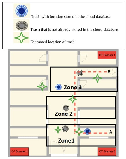
Figure 5.
Experimental setup.
At the start of the experiment, the system will first inquire the position to begin, that is the point A in the map. The user then pushes a key to send information about the starting point. The device will request to enter the destination location that would be an office number. The user then presses the end location. Once the start key is pressed the system gives instructions to start the navigation process. The system will instruct the user by an audio speaker about how to go to the destination that is Point B. These instructions could be like “turn right”, “turn left”, “move forward”, etc. At the point B location, the user will hear the voice “destination arrived”.
Since the system follows the map and helps the visually impaired person to get to a specific location. If obstacles between paths are detected, then the system will inform about these obstacles as well. We tested the system in an experimental environment where a blind person is expected to navigate from the starting position to the destination position while crossing some obstacles. We have performed the experiments three times with a normal person who is not blind.
As shown in the figure, we want to from point A to point B move using the Smart Cane. We put office trashes as obstacles to test the object detection of the system. In this scenario the positions of the blue trash are already stored in the cloud database as obstacles. Whereas, the other trashes are not already stored in the database. We installed three IoT scanners in three corners of the building for location accuracy. Precision of the localization of the Smart Cane was expected to be between 50 cm and 100 cm in an area of 70 m × 50 m. During each experiment, the system includes the detected obstacles in the database and thus can help in the navigation for the user for the next experiments by taking less time for navigation, as shown in Table 1.

Table 1.
Elapsed time with number of obstacles in three experiments.
In our experiment, whenever the user approaches near the blue trash, the cane warns about the presence of the obstacle. The detection occurs because the trash position is already stored in the cloud system. While navigating through the path between A and B. When the cane detects a new obstacle, it will be stored in the cloud in the table of obstacles. This table is used by the system to get the safe way. It is important that the cane remains connected to the cloud, whenever the Smart Cane loses connection with the cloud, it cannot guide the user to navigate to point B.
Table 2 shows the precision accuracy of the Smart Cane navigation system. For all three zone shown in the Figure 5 of experimental setup, it shows precision of estimated location of trashes. It can be seen that the system can accurately determine the location of the obstacles with a precision range of 50 cm to 100 cm. It is to be noticed that as the user moves father from the IoT Scanner 2 and 3, and it effects the accuracy of the object detection system.
Table 2.
Localization precision of the Smart Cane navigation system.
4.2. System Performance
We have tested the performance of the system parameters including battery, connectivity, response time and detection range of the Smart Cane navigation system. All these experiments are performed five times by a person who is not blind. To test the performance of the battery, we keep the cane on until the battery of the cane is completely drained. The capacity of the power bank is 2200-mah. This experiment is performed for all three available modes that are smart navigation mode, Eco mode and offline mode.
For testing the range of obstacle detection, we have put obstacles at different distances from the user to measure the maximum detection range. Obstacles were placed at 1–8 m away from the user to determine the maximum detection range. Each experiment is performed five times and average values are presented in the Table 1. Similarly, to get the average value for response time from the server is also measured five times. It is the time that a message takes to carry information from the cloud server to the Smart Cane. Average values of response time are calculated for all three available modes and are recorded in the Table 1. When the cane loses connection with the sound the system cannot localize the cane indoor. Table 3 presents an analysis of the performance of the system in Smart navigation mode, Eco mode and off-line mode.
Table 3.
Performance of navigation system.
The Table 3 shows the performance of the Smart Cane navigation system in all three modes for different parameters such as battery consumption, maximum range for object detection and time delay. Smart navigation mode is the powerful mode that can detect objects from 500 cm with only 1 ms of communication delay, but it consumes battery at a faster rate. Eco mode can be turned on for smart usage in order to have a longer usage of battery. Offline mode is also helpful when you do not need to have communication with the cloud server, thus it consumes less battery but still can detect the objects in the 400 cm range.
5. Conclusions
Considering that navigation has been a major problem for this segment of people, we have proposed a smart white cane to help blinds in indoor navigation. This system contains micro-controllers, cameras and accelerometers and can send audio messages. A cloud service is exploited to assist the user in navigating from one point to another. It mainly helps in the detection of the fastest routes. The device may also warn about nearby objects using a sonar and a sound buzzer. We have tested our system and the results are very satisfactory. The observed results have shown that the system is capable of assisting navigation. Such results may lead to enhancing product design based on user input. Functionality experiments carried out so far have given practical suggestions for growing the usefulness of the new navigation system. In the near future, we also plan to make the Smart Cane useful even if it loses connection with the cloud. To convert user requirements into design quality, the quality function deployment framework will be used. We also plan to add some intelligence in the Smart Cane navigation system since the field of artificial intelligence is making great progress now and features like objects detection can become more efficient, easier and computationally feasible. We can use extended support vector machines (SVMs), which were initially designed to solve the classification task of medical implant materials, to provide a higher accuracy of the navigation tool. Similarly, to improve the precision of object detection, we can consider using artificial neural networks to solve this problem. The non-iterative feed-forward neural network works much faster than MLP and has a lot of other advantages for solving the stated task.
Author Contributions
Software, hardware, evaluation and data acquisition: M.D.M.; writing—original draft preparation and final version: M.D.M.; writing—review and editing: B.-A.J.M., H.M. All authors have read and agreed to the published version of the manuscript.
Funding
This research was funded by the Natural Sciences and Engineering Research Council of Canada (NSERC). Grant numbers from NSERC are RGPIN-2019-07169 and RGPIN-2017-05521.
Conflicts of Interest
The authors declare no conflict of interest.
References
- Vision Impairment and Blindness. Who.int, 2018. Available online: https://www.who.int/news-room/fact-sheets/detail/blindness-and-visual-impairment (accessed on 30 April 2020).
- Bourne, R.R.A.; Flaxman, S.R.; Braithwaite, T.; Cicinelli, M.V.; Das, A.; Jonas, J.B.; Keeffe, J.; Kempen, J.H.; Leasher, J.; Limburg, H.; et al. Magnitude, temporal trends, and projections of the global prevalence of blindness and distance and near vision impairment: A systematic review and meta-analysis. Lancet Glob. Health 2017, 5, e888–e897. [Google Scholar] [CrossRef]
- Varma, R.; Vajaranant, T.S.; Burkemper, B.; Shuang, W.; Torres, M.; Hsu, C.; Choudhury, F.; McKean-Cowdin, C. Visual impairment and blindness in adults in the United States: Demographic and geographic variations from 2015 to 2050. JAMA Ophthalmol. 2016, 134, 802–809. [Google Scholar] [CrossRef] [PubMed]
- Huh, J.; Seo, K. An indoor location-based control system using Bluetooth beacons for IoT systems. Sensors 2017, 17, 2917. [Google Scholar] [CrossRef] [PubMed]
- Mercado, J.; Chu, G.; Imperial, E.J.; Monje, K.G.; Pabustan, R.M.; Silverio, A. Smart cane: Instrumentation of a quad cane with audio-feedback monitoring system for partial weight-bearing support. In Proceedings of the 2014 IEEE International Symposium on Bioelectronics and Bioinformatics (ISBB), Chung Li, Taiwan, 11–14 April 2014; pp. 1–4. [Google Scholar]
- Jeong, J.P.; Yeon, S.; Kim, T.; Lee, H.; Kim, S.M.; Kim, S. SALA: Smartphone-assisted localization algorithm for positioning indoor IoT devices. Wirel. Netw. 2018, 24, 27–47. [Google Scholar] [CrossRef]
- Link, J.A.B.; Smith, P.; Viol, N.; Wehrle, K. Footpath: Accurate map-based indoor navigation using smartphones. In Proceedings of the 2011 International Conference on Indoor Positioning and Indoor Navigation (IPIN), Guimaraes, Portugal, 21–23 September 2011; pp. 1–8. [Google Scholar]
- Prasithsangaree, P.; Krishnamurthi, P.; Chrysanthis, P.K. On indoor position with wireless LANs. In Proceedings of the IEEE International Symposium on Personal, Indoor and Mobile Radio Communications, Pavilhao Altantico, Lisboa, Portugal, 18 September 2002; Volume 2, pp. 720–724. [Google Scholar]
- Mautz, R.; Tilch, S. Optical Indoor Positioning Systems. In Proceedings of the 2011 International Conference on Indoor Positioning and Indoor Navigation (IPIN), Guimarães, Portugal, 21–23 September 2011. [Google Scholar]
- Kohoutek, T.K.; Mautz, R.; Donaubauer, A. Real-time Indoor Positioning Using Range Imaging Sensors. SPIE Photonics Eur. Real-Time Image Video Process. 2010, 7724. [Google Scholar] [CrossRef]
- Mulloni, A.; Wgner, D.; Schmalstieg, D.; Barakonyi, I. Indoor Positioning and Navigation with Camera Phones. IEEE Pervasive Comput. 2009, 8, 22–31. [Google Scholar] [CrossRef]
- Peterson, B.B.; Kmiecik, C.; Hartnett, R.; Thompson, P.M.; Mendoza, J.; Nguyen, H. Spread spectrum indoor geolocation. J. Inst. Navigat. 1998, 45, 97–102. [Google Scholar] [CrossRef]
- Li, X.; Pahlavan, K.; Latva-aho, M.; Ylianttila, M. Comparison of indoor geolocation methods in DSSS and OFDM wireless LAN. In Proceedings of the Vehicular Technology Conference Fall 2000. IEEE VTS Fall VTC2000. 52nd Vehicular Technology Conference, Boston, MA, USA, 24–28 September 2000; Volume 6, pp. 3015–3020. [Google Scholar]
- Correal, N.S.; Kyperountas, S.; Shi, Q.; Welborn, M. An ultrawideband relative location system. In Proceedings of the IEEE Conference on Ultra Wideband Systems and Technologies, Reston, VA, USA, 16–19 November 2003; pp. 394–397. [Google Scholar]
- Pereiraab, A.; Nunesa, N.; Vieiraa, D.; Costaa, N.; Fernandesc, H.; Barrosoc, J. Blind Guide: An ultrasound sensor-based body area network for guiding blind people. Procedia Comput. Sci. 2015, 67, 403–408. [Google Scholar] [CrossRef]
- Domingo, M.C. An Overview of the Internet of Things for people with disabilities. J. Netw. Comput. Appl. 2012, 55, 584–596. [Google Scholar] [CrossRef]
- Fang, B. Simple solution for hyperbolic and related position fixes. IEEE Trans. Aerosp. Electron. Syst. 1990, 26, 748–753. [Google Scholar] [CrossRef]
- Kanaan, M.; Pahlavan, K. A comparison of wireless geolocation algorithms in the indoor environment. In Proceedings of the 2004 IEEE Wireless Communications and Networking Conference (IEEE Cat. No.04TH8733), Atlanta, GA, USA, 21–24 March 2004; Volume 1, pp. 177–182. [Google Scholar]
- Zhou, J.; Chu, K.M.-K.; Ng, J.K.-Y. Providing location services within a radio cellular network using ellipse propagation model. In Proceedings of the 19th International Conference on Advanced Information Networking and Applications (AINA’05) Volume 1 (AINA papers), Taipei, Taiwan, 28–30 March 2005; pp. 559–564. [Google Scholar]
- Teuber, A.; Eissfeller, B. Atwo-stage fuzzy logic approach forwireless LAN indoor positioning. In Proceedings of the 2006 IEEE/ION Position, Location, And Navigation Symposium, Coronado, CA, USA, 25–27 April 2006; Volume 4, pp. 730–738. [Google Scholar]
- Pahlavan, K.; Li, X.; Makela, J. Indoor geolocation science and technology. IEEE Commun. Mag. 2002, 40, 112–118. [Google Scholar] [CrossRef]
- van Veen, B.D.; Buckley, K.M. Beamforming: A versatile approach to spatial filtering. IEEE ASSP Mag. 1988, 5, 4–24. [Google Scholar] [CrossRef]
- Ottersten, B.; Viberg, M.; Stoica, P.; Nehorai, A. Exact and large sample ML techniques for parameter estimation and detection in array processing. In Radar Array Processing; Haykin, S.S., Litva, J., Shepherd, T.J., Eds.; Springer: New York, NY, USA, 1993; pp. 99–151. [Google Scholar]
- Kontkanen, P.; Myllymaki, P.; Roos, T.; Tirri, H.; Valtonen, K.; Wettig, H. Topics in probabilistic location estimation inwireless networks. In Proceedings of the 2004 IEEE 15th International Symposium on Personal, Indoor and Mobile Radio Communications, Barcelona, Spain, 5–8 September 2004. [Google Scholar]
- Köhler, M.; Patel, S.; Summet, J.; Stuntebeck, E.; Abowed, G. TrackSense: Infrastructure Free Precise Indoor Positioning Using Projected Patterns. Pervasive Comput. LNCS 2007, 4480, 334–350. [Google Scholar]
- Cristianini, N.; Shawe-Taylor, J. An Introduction to Support Vector Machines; Cambridge University Press: Cambridge, UK, 2000; Available online: http://www.support-vector.net (accessed on 10 March 2020).
- Brunato, M.; Battiti, R. Statistical learning theory for location fingerprinting in wireless LANs. Comput. Netw. 2005, 47, 825–845. [Google Scholar] [CrossRef]
- Wu, C.L.; Fu, L.C.; Lian, F.L. WLAN location determination in ehome via support vector classification. In Proceedings of the IEEE International Conference on Networking, Sensing and Control, Taipei, Taiwan, 21–23 March 2004; Volume 2, pp. 1026–1031. [Google Scholar]
- Evolution Robotics. 2010. Available online: http://www.evolution.com (accessed on 12 March 2020).
- Lee, H.S.; Lee, S.H.; Lee, J.G.; Lee, J.K. Design of Beacon-Based Positioning System Using RF and Sound Wave in Smartphone. In Advances in Computer Science and Ubiquitous Computing. CUTE 2017, CSA 2017; Park, J., Loia, V., Yi, G., Sung, Y., Eds.; Lecture Notes in Electrical Engineering 2018; Springer: Singapore, 2017; Volume 474. [Google Scholar]
- Bu, Y.; Seo, K.; Huh, J.-H. A study of enhancement of ranging performance of beacons through the improvement of the smart phone’s gyroscope: Focusing on the Bluetooth low energy. In Proceedings of the 11th International Conference on Ubiquitous Information Management and Communication (ACM IMCOM), Beppu, Japan, 5–7 January 2017; p. 90. [Google Scholar]
- Muffert, M.; Siegemund, J.; Förstner, W. The Estimation of Spatial Positions by Using an Omnidirectional Camera System. In Proceedings of the 2nd International Conference on Machine Control & Guidance, Bonn, Germany, 9–11 March 2010; pp. 95–104. [Google Scholar]
- Wahab, M.H.A.; Talib, A.A.; Kadir, H.A.; Johari, A.; Noraziah, A.; Sidek, R.M.; Mutalib, A.A. Smart cane: Assistive cane for visually-impaired people. arXiv 2011, arXiv:1110.5156. [Google Scholar]
- Naiwrita, D.; Paul, A.; Ghosh, P.; Mukherjee, C.; De, R.; Dey, S. Ultrasonic Sensor Based Smart Blind Stick. In Proceedings of the 2018 International Conference on Current Trends towards Converging Technologies (ICCTCT), Coimbatore, India, 1–3 March 2018; pp. 1–4. [Google Scholar]
- Shah, H.R.; Uchil, D.; Rane, S.S.; Shete, P. Smart stick for blind using arduino, ultrasonic sensor and android. Int. J. Eng. Sci. 2017, 7, 10929–10933. [Google Scholar]
- Wade, J.; Beccani, M.; Myszka, A.; Bekele, E.; Valdastri, P.; Flemming, P.; Riesthal, M.; Withrow, T.; Sarkar, N. Design and implementation of an instrumented cane for gait recognition. In Proceedings of the 2015 IEEE International Conference on Robotics and Automation (ICRA), Seattle, WA, USA, 26–30 May 2015; pp. 5904–5909. [Google Scholar]
- Lipson, B.L.; Thomas, D.; Dharani, P.I. RFID Navigation System for the Visually Impaired. April 2012. Available online: https://digitalcommons.wpi.edu/mqp-all/4038 (accessed on 30 April 2020).
- Du, H.; Zhang, C.; Ye, Q.; Xu, W.; Kibenge, P.L.; Yao, K. A hybrid outdoor localization scheme with high-position accuracy and low-power consumption. EURASIP J. Wirel. Commun. Netw. 2018. [Google Scholar] [CrossRef]
- Gunther, A.; Hoene, C. Measuring round trip times to determine the distance between WLAN nodes. In Proceedings of the Networking 2005, Waterloo, ON, Canada, 2–6 May 2005; pp. 768–779. [Google Scholar]
- HC-SR04 Ultrasonic Range Finder, robotshop.com. Available online: https://www.robotshop.com/en/hc-sr04-ultrasonic-range-finder-osepp.html (accessed on 30 April 2020).
- ADXL337 and ADXL377 Accelerometer Hookup Guide—learn.sparkfun.com. Learn.sparkfun.com. 2019. Available online: https://learn.sparkfun.com/tutorials/adxl337-and-adxl377-accelerometer-hookup-guide/all (accessed on 30 April 2020).
- Charmed Labs Pixy 2 CMUcam5 Image Sensor. robotshop.com. Available online: https://www.robotshop.com/en/charmed-labs-pixy-2-cmucam5-image-sensor.html (accessed on 30 April 2020).
- A. Industries. Emic 2 Text-to-Speech Module. Adafruit.com. 2018. Available online: https://www.adafruit.com/product/924 (accessed on 30 April 2020).
- Zhao, N. Full-featured pedometer design realized with 3-axis digital accelerometer. Analog Dialogue 2010, 44, 1–5. [Google Scholar]


© 2020 by the authors. Licensee MDPI, Basel, Switzerland. This article is an open access article distributed under the terms and conditions of the Creative Commons Attribution (CC BY) license (http://creativecommons.org/licenses/by/4.0/).