Abstract
Cryogenic technologies are a crucial field of modern engineering, with applications in liquefied gas transport, renewable energy, aerospace, and high-precision medicine. Their advancement relies heavily on the performance and reliability of cryogenic tanks, which ensure the safe storage and handling of fluids at extremely low temperatures. This paper presents a concise review of recent engineering innovations, focusing on fluid behavior in single- and two-phase regimes, boil-off mechanisms, advanced thermal insulation, and energy loss control strategies. Recent numerical and experimental studies indicate that optimized insulation configurations, such as the placement of a low-emissivity intermediate layer near the cold wall, can reduce radiative heat loads by approximately 40–60%, thereby significantly mitigating cryogenic liquid boil-off. Developments in structural materials, functional coatings, and numerical simulations are also discussed, as they contribute to enhancing tank efficiency under demanding operational conditions. Particular emphasis is placed on material selection and surface engineering solutions aimed at reducing corrosion, improving cryogenic resistance, and extending service life. These approaches not only lower maintenance costs but also strengthen safety and sustainability in cryogenic applications. In addition, current industry trends are highlighted, including equipment miniaturization, integration into mobile platforms, and the adoption of international standards for safety and efficiency. The paper aims to provide an interdisciplinary synthesis that supports both academic research and the development of durable, high-performance cryogenic systems.
1. Introduction
Liquefied gases and their associated technologies have become an indispensable component in multiple engineering fields, particularly where extreme temperatures provide functional advantages that are difficult to match [1]. These fluids, including liquid nitrogen, oxygen, hydrogen, and helium, are characterized by complex thermodynamic behavior involving properties such as high thermal conductivity, elevated specific heat capacity, and controlled volatility at low pressures [1,2,3,4,5,6]. Their relevance derives not only from their specific physico-chemical properties but also from their adaptability within high-performance engineering systems [4].
The practical use of liquefied gases requires the implementation of sophisticated storage and handling systems, particularly cryogenic tanks optimized both structurally and thermally [5]. These tanks must ensure the stable maintenance of liquids, prevent boil-off losses, and guarantee material compatibility under repeated thermal cycling [7]. In this regard, material selection becomes essential, focusing on resistance to embrittlement, corrosion, and thermal shock criteria that go beyond simple mechanical strength [8,9].
Over the past few decades, applied cryogenics research has led to major progress in the use of special alloys, composite materials, and functional coatings that enhance the performance of cryogenic systems [10,11]. Significant advances have been made in thermal insulation systems, such as multilayer insulation (MLI) and partial vacuum structures, which minimize parasitic heat fluxes [12]. These solutions extend cryogen hold time in applications such as maritime or aerospace transport, reducing the need for frequent refilling [13].
In parallel with material development, numerical analysis and fluid-dynamic modeling have provided new insights into the behavior of liquefied gases under single-phase and two-phase regimes [11]. Computational fluid dynamics (CFD) models enable the prediction of flow instabilities, boil-off phenomena, and risks associated with localized heat losses or cavitation effects [14]. The integration of such models into engineering design has allowed geometric optimization of tanks and direct correlation with functional performance under dynamic operating conditions [15].
Industrial and commercial applications of these technologies are expanding rapidly. In the energy sector, for example, cryogenic tanks are used for storing liquid hydrogen as a clean energy vector, directly supporting global decarbonization objectives [16]. In the food industry, liquid nitrogen is essential for rapid freezing and preservation of sensitive products, while in advanced medicine, liquid helium is critical for cooling superconducting magnets in devices such as magnetic resonance imaging (MRI) systems [4].
Another emerging direction involves mobile and space applications, where cryogenic systems are integrated into transport platforms exposed to mechanical shocks, vibrations, and pressure variations [17]. In these contexts, component reliability becomes critical, requiring functional surface coatings of tank interiors to reduce chemical interactions and impurity migration [18].
Given this multidisciplinary complexity, the present article aims to provide an integrative analysis of recent innovations in liquefied gases and cryogenic tanks, emphasizing the interactions between material performance, fluid behavior at the engineering scale, modern analysis methods, and emerging industrial applications. Through this approach, the study seeks to deliver a comprehensive synthesis to support researchers, engineers, and decision-makers in optimizing and sustainably implementing liquefied gas storage capacity.
In this context, the future of sustainable energy systems is closely linked to the use of liquefied gases—particularly liquid oxygen and hydrogen—as vectors of green energy. Their integration into modern energy infrastructure offers real prospects for reducing carbon emissions and improving the efficiency of energy storage and transport systems.
This paper, therefore, aims to explore this technological evolution through an in-depth analysis of the latest advances in the design, optimization, and application of cryogenic tanks in the transition toward green energy. The focus is placed on the role of liquefied gases in emerging energy paradigms, highlighting the connection between the engineering performance of storage systems and current requirements for sustainability, efficiency, and industrial adaptability.
2. Liquefied Gases and Their Dynamic Behavior
Cryogenic liquids are substances that exist in liquid form at extremely low temperatures, often below 123 K, where their physical-chemical properties differ significantly from those observed at ambient conditions [1]. Within this temperature range, thermodynamic behavior, heat transfer capacity, and interactions with the surrounding environment become critical factors for any engineering application [6]. These fluids are essential in cutting-edge technologies, from the storage and transport of energetic gases such as liquid hydrogen to applications in the food industry, modern medicine, and superconducting computing systems [4]. Their importance derives not only from their unique properties but also from the engineering challenges associated with their safe handling.
Cryogenic liquids also play a significant role in the circular economy, being used in waste-heat recovery and reuse systems, or in advanced preservation processes that reduce food waste [10]. This convergence between technological performance and environmental sustainability highlights the growing need for standardization, engineering optimization, and interdisciplinary research in applied cryogenics. As global energy systems shift toward decarbonization and sustainability, cryogenic liquids—particularly liquid hydrogen—are becoming central pillars in strategies for the storage and transport of clean energy. At the same time, their use involves a complex interplay of heat transfer phenomena, phase dynamics, thermal processing, and material compatibility [7].
A liquid is considered cryogenic when its boiling point falls below 123 K, requiring specialized systems to maintain the liquid phase [2]. The most common cryogenic liquids include: liquid nitrogen (77 K), liquid oxygen (90 K), liquid hydrogen (20 K), and liquid helium (4 K), each with distinct applications depending on their physical properties [1,6].
A comparative overview of frequently used cryogenic liquids shows significant differences in boiling point and reactivity. For instance, liquid oxygen (90 K) is a strong oxidizer, whereas liquid helium is completely inert but has an extremely low heat capacity, making it ideal for cooling superconducting systems [6].
Historically, the use of cryogenic liquids began with laboratory research on gas liquefaction and was later applied to aerospace engineering, particularly through the use of liquid hydrogen and oxygen in rocket propulsion [5]. In recent decades, driven by the energy transition, interest has expanded toward industrial and commercial applications, owing to their potential in renewable energy storage, efficient cooling technologies, and quantum applications [10].
In thermal engineering, it is essential to distinguish between cryogens used for direct cooling and refrigerants employed in closed circuits. The former come into direct contact with the cooled material or medium (e.g., LN2 in food processing), while the latter circulate in compression–expansion systems (e.g., helium for indirect cooling in particle accelerators) [5].
The pressure–temperature relationship is also critical. For example, when the temperature drops below the boiling point without a corresponding pressure reduction, cryogenic liquids may undergo direct vaporization through flash evaporation. Modeling this phase transition is essential for the design of tanks and pipelines, particularly under transient regimes or in cases of vacuum loss [7].
These fluids can also be classified according to several engineering criteria. A primary criterion is their chemical nature: inert liquids, such as nitrogen and helium, do not engage in chemical reactions under normal operating conditions and are therefore employed in processes where stability is crucial (e.g., food cooling, thermal testing systems) [12]. In contrast, reactive liquids, such as liquid hydrogen and liquid oxygen, are indispensable in controlled combustion applications and propulsion technologies [10]. This classification is explained schematically in Figure 1.
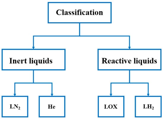
Figure 1.
Classification of cryogenic liquids based on their chemical reactivity, distinguishing between inert liquids and reactive liquids.
A second criterion, also explained by means of Table 1, concerns the field of applicability: some liquids are employed in food-related cryogenic processes (liquid nitrogen) [12], others in fundamental research (liquid helium in quantum physics experiments) [4], while liquid hydrogen is widely used in energy storage and transport systems [10]. Classification according to the level of hazard is also essential, particularly in the design of insulation and safety systems [4]. Therefore, comprehensive documentation of each cryogenic liquid, considering reactivity, toxicity, diffusivity, and explosive potential, is a prerequisite for any engineering project [8].

Table 1.
Fields of application of liquefied gases.
A thorough understanding of the nature of these fluids requires a detailed analysis of how they are stored and transported under conditions of safety, efficiency, and sustainability. Accordingly, the following section presents the engineering technologies dedicated to this purpose.
Storage and transport systems for liquefied gases are designed to ensure the maintenance of extremely low temperatures, prevent fluid losses, and mitigate the thermodynamic risks involved [5]. These requirements necessitate the use of cryo-resistant materials and multi-chamber architectures, incorporating multilayer insulation under vacuum or high-performance foams [6].
In the case of liquid hydrogen storage, both experimental and numerical studies indicate that the thermal dynamics of the fluid under static conditions are strongly influenced by tank geometry, insulation thickness, and the presence of thermal bridges [7]. The phenomenon of thermal stratification leads to the formation of warmer regions at the top, promoting evaporation and pressure build-up. To counteract these effects, calibrated safety valves, axially distributed temperature sensors, and passive or active venting systems are employed [7].
Experimentally validated CFD simulations have shown that the introduction of baffles and optimization of the insulation layer distribution can significantly reduce boil-off losses [9]. Furthermore, the structure of the inner tank walls influences vapor bubble formation [1], while the use of low thermal conductivity materials (such as metal–polymer composites) helps maintain stable cryogenic conditions [5].
For food and medical applications, portable containers—pressurized or equipped with cryogenic sprayers—are commonly employed, allowing direct transfer of liquid nitrogen into processing zones. These systems must comply with hygiene and non-toxicity regulations, while accidental contact with exposed components must be prevented through ergonomic design and automated control [12].
Efficient storage of these fluids would be meaningless without a well-defined practical purpose. For this reason, it is equally important to highlight the fields in which cryogenic liquids are industrially and scientifically exploited, contributing to the technological transformation of society.
Liquefied gases have become indispensable components in high-technology industries, where extreme thermal control is critical. In the energy sector, liquid hydrogen is employed as an energy carrier for large-scale transport and storage, offering a viable solution for carbon emission reduction [10]. Recent progress in liquefaction efficiency and in no-vent storage systems enables the implementation of these technologies in commercial applications [7].
In the aerospace industry, liquefied gases are used as primary propellants in rocket propulsion [5]. Liquid hydrogen and liquid oxygen form one of the most efficient combinations in terms of specific impulse, being critical for orbital and interplanetary missions [10].
In the food industry, liquid nitrogen is employed for the rapid cryogenic freezing of sensitive products, which preserves cellular structure and organoleptic qualities. This method is highly valued for its fast cooling rate and the absence of chemical contaminants [12].
In scientific research, liquid helium is applied for cooling highly sensitive detectors in particle physics [4], while liquid nitrogen is indispensable in molecular biology laboratories for sample preservation [5].
At the same time, cryogenic applications in the field of electronic memory involve the development of superconducting circuits operating at temperatures of only a few kelvins. These systems provide minimal latency and enhanced energy efficiency in quantum computing platforms or ultra-low-power data centers [4].
Figure 2 illustrates the main industrial sectors in which liquefied gases-namely oxygen, nitrogen, and hydrogen-are applied, highlighting their roles across energy, aerospace, biomedical, food, chemical, and pharmaceutical industries.
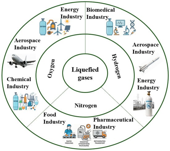
Figure 2.
Overview of major industrial applications of liquefied gases (oxygen, nitrogen, and hydrogen).
Nevertheless, beyond their remarkable performance, the associated risks must also be considered. A comprehensive analysis requires accounting for safety, operational stability, and the compatibility of the materials involved.
The use of liquefied gases entails multiple technical hazards, ranging from equipment degradation to threats to human health. Extreme temperatures can cause severe frostbite, while direct contact with skin or eyes leads to immediate and deep tissue damage [8]. To prevent such incidents, the mandatory use of personal protective equipment is required, including cryogenic gloves, face shields, and insulating clothing [5]. Another major risk concerns the build-up of internal pressure in closed tanks due to the spontaneous evaporation of the liquid [5]. Without effective pressure-relief valves, the pressure may exceed allowable limits, leading to container cracking or localized explosions [6]. Experimental studies have shown that the rate of pressure increase is highly sensitive to insulation defects and external temperature fluctuations [7].
In the case of liquid hydrogen, the hazard is amplified by its flammability and the high diffusivity of the resulting gas [7]. In confined spaces, the accumulation of hydrogen gas can lead to explosive mixtures, necessitating the implementation of gas sensors, forced ventilation, and optical detection systems [10].
Materials in contact with cryogenic fluids are also susceptible to embrittlement-the phenomenon of low-temperature-induced brittleness-which can compromise the structural integrity of the tank [1]. Tests conducted on metallic alloys have revealed significant reductions in ductility at cryogenic temperatures, underscoring the need for careful selection of structural components [3].
Liquefied gases, due to their extreme sensitivity to temperature and pressure variations, represent a critical field in advanced engineering. These fluids are employed in applications ranging from space propulsion and fuel transport to quantum materials research, particle physics, and emerging ultra-efficient cooling technologies [18]. Because they are maintained at extremely low temperatures-typically below 123 K and sometimes close to 0 K-they exhibit thermodynamic and hydrodynamic behaviors that differ substantially from conventional fluids [19].
From a technological perspective, cryogenics has become indispensable in the development of hydrogen and oxygen liquid propulsion systems (LH2/LOX), where flow dynamics, mixing, and evaporation are strongly interconnected and critically influence overall engine performance [18]. Moreover, phenomena such as boil-off instabilities, cavitation at low pressures, bubble formation, and two-phase flows are almost unavoidable in practical systems, requiring a detailed understanding of their phenomenology [20].
The main flow regimes encountered in cryogenic systems, together with their thermodynamic states, dominant physical phenomena, and engineering implications, are summarized in Table 2.
Table 2.
Classification of cryogenic flow regimes and governing characteristics.
A central aspect of cryogenic dynamics is the local variation in density and viscosity, which can significantly affect flow even under apparently isothermal conditions. These variations are amplified in the presence of external forces—such as inertial accelerations, microgravity [21,22,23], or applied heat gradients—leading to complex instabilities such as thermocapillary effects or thermal stratification [24].
It is important to note that in many cases, liquefied gases do not behave as ideal Newtonian fluids but may display non-Newtonian characteristics or behaviors dependent on thermal history [25], as observed in unstable helium jets or in subcritical–supercritical transition regimes [26]. Consequently, research in this field requires a synthesis of experimental investigation, mathematical modeling [20], and high-fidelity numerical simulations, all necessary for accurately describing the phenomena involved [27].
The flow regimes observed in liquefied gases are influenced by a considerable number of thermodynamic and hydrodynamic factors [20], including system pressure, local temperature, degree of evaporation, and geometric configuration of the installation. The cryogenic nature of these fluids accentuates phase transitions and necessitates careful classification of flow types depending on the phases present and their stability [21].
Single-phase flow occurs when the fluid remains entirely liquid or gaseous throughout the transport process, typically in well-insulated systems where energy losses are minimal, and temperatures are consistently maintained below the saturation point [28]. Under these conditions, classical analysis methods similar to those applied to Newtonian regimes may be used [29]. However, in most practical applications, operating temperatures approach the boiling point, leading to vapor phase formation and thus two-phase flow [20].
The two-phase regime is specific to systems where liquid and vapor coexist, often in unstable equilibrium due to sudden pressure variations or external heat influx [20]. This metastable state generates a series of interfacial phenomena, such as bubble formation, coalescence, and pressure waves, which strongly affect overall flow dynamics [23].
When the fluid is brought to extreme thermodynamic conditions beyond the critical point, a supercritical regime is reached. This state is characterized by the absence of a clear boundary between liquid and vapor phases and by continuous variations of density and other properties, which greatly complicate mathematical modeling and system control [21].
Interestingly, subcritical and supercritical regimes may temporarily coexist within the same system, depending on local conditions [24], especially in configurations with nonuniform heating zones or systems subjected to rapid external perturbations [17]. For example, in aerospace applications, pressure drops during flight can instantly trigger a phase transition that dramatically alters flow behavior [16].
For the efficient design of cryogenic systems, it is essential to accurately identify the predominant flow regime, as this dictates the choice of calculation models, pipe geometry, insulation type, and operating conditions. Misidentification of the regime may lead to cavitation [20], excessive evaporation losses, or mechanical failures caused by overpressure [29].
Given the varied fluid behaviors and engineering challenges associated with flow regimes, the next logical step is to examine in detail the behavior of cryogenic jets. These represent an interface between fluid dynamics and mass and energy transfer, being essential for applications such as fuel injection, controlled atomization, and targeted cooling.
The behavior of jets formed by liquefied gases constitutes a critical area in the analysis of injection, atomization, and advanced cooling systems. These jets, due to the extremely low temperature and the high thermophysical sensitivity of the fluid, are subject to instabilities fundamentally different from those observed in conventional water or hydrocarbon jets [25].
The breakup mechanism of a jet, known as Rayleigh–Plateau instability, applies only under isothermal conditions with constant surface tension [25]. In cryogenic fluids, however, surface tension varies significantly with temperature, while thermal interactions with the surrounding environment induce interfacial vaporization, destabilizing the jet structure from the nucleation zone onward [26].
Experimental studies on liquid helium jets have revealed the occurrence of spontaneous three-dimensional oscillations even in the absence of external forces, indicating the presence of intrinsic self-instability mechanisms. These phenomena are associated in the literature with quantum behaviors of superfluid helium, as well as with local variations in density and enthalpy amplified by heat flux [25].
In applied cryogenic system engineering, jet stability is critical to ensuring efficient mass and energy transfer. In rocket engine combustion chambers, any perturbation of the jet—whether thermal or induced by structural vibrations—may affect fuel mixing quality and, consequently, combustion efficiency [18]. In such cases, fluctuations in the injection flow can lead to acoustic instabilities, where the interaction between pressure and flow rate produces dangerous oscillations in operating conditions [18].
Advanced CFD simulations have highlighted the crucial role of interfacial evaporation, as well as the influence of ambient pressure on jet stability. The models employed must account not only for flow and heat transfer but also for rapid phase change, thermal stratification, and temperature-dependent fluid properties [27].
Thus, the behavior of cryogenic jets cannot be reduced to analogies with conventional liquids [25]. A rigorous approach is required, integrating local thermodynamic effects, variable interfacial properties, and intrinsic dynamic instabilities generated by the unique nature of these fluids [26].
The analysis of instabilities and the dynamics of cryogenic jets highlights the complexity of the physical phenomena that must be understood and controlled in engineering applications. However, in order to anticipate the behavior of these fluids under real-world scenarios, it is essential to employ advanced computational tools. This underscores the importance of numerical modeling and CFD simulations, which provide a rigorous predictive framework for phenomena such as phase transition, interfacial interactions, and dynamic instabilities in cryogenic regimes.
Numerical modeling of the behavior of liquefied gases poses several challenges due to their biphasic nature, the strong variation in physical properties with temperature, and the presence of rapid transitions between states of aggregation. Unlike conventional fluids, the numerical simulation of cryogenic flows cannot neglect any of the transport processes involved, whether thermal, mass, or momentum transfer [20].
One of the most widely used methods for describing the behavior of such fluids is the volume of fluid (VOF) technique, in which the interface between liquid and vapor phases is explicitly tracked within a three-dimensional computational grid. This approach is efficient in simulating vaporization processes, bubble formation, and the development of unstable jets, but it requires advanced numerical stabilization schemes to handle interfacial discontinuities [27].
For systems in which phases coexist in interpenetrating volumes without a clearly defined interface, Euler–Euler models are preferred. These treat each phase as a continuous fluid, interacting through coupling terms of mass, momentum, and energy exchange [20]. Such models are useful for analyzing homogeneous two-phase regimes, such as boil-off in storage tanks or flow through pressurized cryogenic pipelines [24].
Particular attention must be paid to the definition of thermophysical properties in simulations. Key parameters such as density, viscosity, thermal conductivity, and specific heat cannot be assumed constant but must be expressed through nonlinear functions or experimental datasets for each cryogenic fluid [20]. Any error in interpolating these data can severely affect simulation accuracy.
For specialized regimes, such as those involving superfluid helium jets or nanoparticle-doped cryogenic droplets, classical CFD approaches become insufficient [25]. In these cases, alternative techniques such as Lattice Boltzmann or Smoothed Particle Hydrodynamics (SPH) are employed. These particle-oriented methods provide a discrete description capable of capturing interfacial phenomena, condensation, and the propagation of perturbations with high resolution [26].
Based on these numerical modeling approaches, the main computational methods used for simulating cryogenic flows, together with their suitable regimes, key capabilities, and limitations, are summarized in Table 3.
Table 3.
Numerical methods for specialized cryogenic flow regimes.
Another critical aspect is the treatment of boundary conditions, especially when simulations target systems in microgravity or under thermal cycling. In such contexts, numerical approaches require adaptive boundary conditions and perturbation-sensitive discretization schemes to capture the onset of instabilities, thermal stratification, or oscillatory regimes [27].
Thus, numerical modeling of cryogenic flows requires a balance between the physical fidelity of the models, the numerical robustness of the solution methods, and continuous validation against high-precision experimental data [20,21,22,23,24,25,26,27].
Once the fundamentals of numerical modeling are established, it becomes crucial to analyze in depth the mechanisms of heat transfer, as these directly govern fluid stability, vaporization rates, and the overall efficiency of cryogenic systems. In this context, the phenomenon of boil-off is not merely an energy loss but also a sensitive indicator of overall thermal performance, which is why it is treated as a central engineering issue in the design and optimization of cryogenic installations.
Within cryogenic systems, heat transfer mechanisms are directly responsible for the onset and evolution of the boil-off phenomenon—the process by which part of the stored liquid vaporizes uncontrollably due to thermal influx from the external environment [18]. Since liquefied gases possess a high latent heat of vaporization, even a low heat flux can lead to significant mass losses, affecting both system efficiency and operational stability [19].
The physical mechanisms governing heat transfer and the resulting boil-off process in cryogenic storage systems are schematically illustrated in Figure 3.
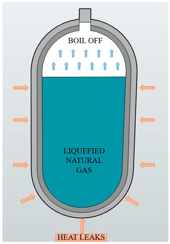
Figure 3.
Schematic illustration of the boil-off phenomenon in a cryogenic liquefied natural gas (LNG) tank.
In passively insulated regimes, heat losses occur mainly through thermal radiation and conduction across structural points such as mechanical supports or joints. This thermal energy flux induces a vapor layer in the upper region of the tank, where thermal stratification develops and a saturation front forms between the liquid and vapor phases. In the absence of active control, this layer evolves progressively, increasing internal pressure and forcing the system to vent vapor—a highly undesirable process for long-duration applications [24].
In stratified cryogenic storage tanks, internal thermal non-uniformities may evolve toward unstable configurations, leading to sudden mixing between liquid layers of different temperatures, commonly referred to as rollover events. Such transient instabilities can induce a sharp escalation in evaporative losses, with the boil-off gas generation rate increasing by more than an order of magnitude compared to nominal operating conditions. Reported observations indicate peak boil-off levels reaching approximately ten to twenty times the steady-state rate, underscoring the pronounced sensitivity of cryogenic systems to internal heat redistribution and highlighting the importance of effective thermal control strategies [30].
To reduce such losses, several engineering solutions have been developed, including multilayer insulation (MLI), the introduction of radiation shields, and the active use of cryogenic condensers, which extract generated vapor and reliquefy it under a mass-conserving regime [19]. The Zero Boil-Off (ZBO) technology, applied in NASA missions, combines active cooling, pressure control, and recondensation to completely eliminate vapor losses during long-term storage [25].
At the microscopic level, the boil-off process is governed by heat transfer mechanisms at the liquid–vapor interface. Studies have shown that non-uniform heat distribution along the tank wall leads to localized regions of intense vaporization, which can generate unstable bubbles and accelerate fluid losses [22]. Furthermore, nucleate or convective instabilities may appear when thermal gradients are not uniformly controlled, particularly in complex geometrical configurations.
An additional challenge arises from the non-uniform behavior of fluids under microgravity, where natural convection is diminished, and heat transport depends largely on conduction within the liquid layer and on vapor redistribution through oscillatory motions induced by vibrations or external perturbations [17].
To effectively understand and control these processes, experimental research is complemented by advanced simulations of temperature fields and heat flux, which allow for the identification of critical zones within the system. These simulations must account for both two-phase modeling and the effects of thermal expansion and density variation [19].
Thus, in any engineering application involving the storage or handling of liquefied gases, thermal system design becomes a determining factor, as it directly defines the boil-off rate and, consequently, the operational lifetime and overall safety of the installation. Cooling and thermal management techniques applied in cryogenic tanks reflect a combination of thermodynamic principles, structural innovations, and active control methods aimed at ensuring long-term system stability under diverse operating conditions.
The cooling process in cryogenic tanks exhibits distinct characteristics compared to pipelines, being influenced by the three-dimensional configuration of the closed space, filling conditions, and thermomechanical interactions between the fluid and structural walls. This complexity justifies the need for dedicated studies that separately address the thermal behavior of these systems. For example, Wang et al. [31] implemented two finite-difference schemes to characterize the filling performance of a liquid hydrogen (LH2) tank. Similarly, Leclair and Majumdar [32] developed a numerical model capable of simultaneously simulating the cooling and fueling of LOX and LH2, successfully estimating the thermal stabilization time of the tank.
Thermal dynamics modeling has also been extended to LNG (liquefied natural gas) applications, where Lu et al. [33] proposed a CFD approach to evaluate the thermodynamic response of a transport tank, with emphasis on improving prediction reliability. In parallel, Hedayat and colleagues [34] developed an advanced model combining heat transfer and hydrodynamics to describe cryogenic behavior during filling and cooling of an LH2 tank, demonstrating a precise correlation between liquid level and internal pressure.
During cooling, the progressive accumulation of cryogenic liquid induces a rapid decrease in tank wall temperature, resulting in steep thermal gradients and, consequently, the development of thermal stresses in the structural material. This problem has attracted significant attention in the literature. For instance, Fedorov and Luk′yanova [35] emphasized that filling strategy can influence temperature distribution and stress levels, observing that top-filling reduces thermal stresses significantly. Cheng et al. [36] derived analytical formulas to estimate mechanical stresses in cylindrical walls under cryogenic cooling, reporting circumferential stresses that may exceed 50% of the tensile strength of the material.
From a numerical modeling perspective, Zhu et al. [37] applied finite element analysis to evaluate transient stress behavior in tank walls, highlighting the influence of insulation configuration. Sassine and colleagues [38] adopted a discrete element approach, capturing the time evolution of internal stresses with high accuracy. Ma et al. [39,40] complemented this picture through simulations of a small-scale tank, demonstrating a clear relationship between cooling rate and structural deformation intensity.
Experimental validation of these models was provided by Zhu and colleagues [41], who analyzed the behavior of a 100 L aluminum tank during liquid nitrogen filling.
Results indicated an increase in thermal stresses proportional to filling rate, suggesting a higher risk of structural overload under rapid dynamic conditions [41,42].
Despite significant advances in simulation and testing, notable gaps remain in the detailed understanding of the phenomenology associated with cryogenic tank cooling. Most studies focus on temperature distribution analysis, often neglecting the impact of thermal stress on structural durability. Therefore, the study of stress distribution during cooling phases becomes a critical priority in the development of reliable and safe cryogenic systems [43].
The applicability of cooling and thermal management techniques extends beyond theoretical or experimental aspects, being integrated into numerous functional engineering systems. These solutions are embedded in complex structures optimized for cutting-edge domains such as space propulsion, cryogenic fuel transport, and research facilities. Accordingly, an overview of how these fluids are practically utilized in advanced, interdisciplinary cryogenic systems is essential.
Liquefied gases are widely employed across a variety of advanced engineering systems, particularly in the aerospace, energy, and applied research sectors. Their exceptional thermophysical characteristics—such as high density, elevated latent heat of vaporization, and storage capacity at extremely low temperatures—make them indispensable in applications where efficient energy transfer or propulsion is required [28].
In space propulsion, cryogenic applications primarily involve the use of liquid hydrogen and liquid oxygen in high-performance injection and combustion systems. These impose stringent requirements for flow control, fuel atomization, and stability under highly variable pressure and temperature regimes [18]. Cryogenic injection systems must ensure stable flow and uniform distribution while avoiding cavitation phenomena and parasitic vaporization losses [28].
In this context, direct cryogenic injection systems have been developed, where mixture dynamics play a critical role in combustion processes [11]. Controlling operational parameters of such systems, including injection frequency, nozzle geometry, and synchronization between liquid and gaseous phases, require advanced numerical modeling and experimental validation [18].
Another category of applications is represented by the transport and storage of cryogenic fuels in isolated or space environments. In such cases, components such as pipelines, pumps, and tanks are designed to minimize boil-off, withstand pressure variations, and prevent the onset of instability or thermally induced mechanical stress [25]. Cryogenic pipelines, for instance, must be analyzed not only for mechanical resistance but also for thermal compatibility with the working fluid, in order to avoid differential expansion and potential cracking [29].
Applications extend beyond aerospace. In scientific research facilities, liquefied gases are used to achieve ultra-low temperatures required in the study of superconducting materials, Bose–Einstein condensates, or cooling systems for particle accelerators. In these applications, controlled heat distribution and thermal uniformity are essential conditions for experimental stability [28].
The development of cryogenic components requires the integration of multiple engineering disciplines—thermodynamics, fluid mechanics, materials science, and automated control [11]. All of these must be harmonized to achieve a functional, safe, and long-term efficient system, regardless of the complexity of the operational environment [24].
The main application domains of liquefied gases, together with their specific uses and associated engineering challenges, are summarized in Table 4.
Table 4.
Application domains of liquefied gases and associated engineering challenges.
Although cryogenic applications have made remarkable progress in recent decades, the complexity of these systems and the extreme conditions under which they operate continue to pose significant challenges. Current limitations in measurement, modeling, and control of dynamic phenomena highlight the need for advanced research and the development of innovative technological solutions.
The dynamics of liquefied gases remains a highly active research field, where the complexity of thermohydraulic phenomena and the limitations of experimental instrumentation create substantial difficulties in fully understanding the behavior of these fluids [20]. Their biphasic nature, rapid transitions between aggregation states, and strong dependence of physical properties on thermal and pressure parameters lead to instabilities that are difficult to predict and control in real applications [21].
One of the central issues lies in the realistic numerical modeling of these phenomena. Although CFD methods have evolved considerably—particularly through the use of adaptive algorithms and multiphase simulation techniques—the accuracy of simulations remains constrained by the lack of precise experimental data under extreme conditions [20]. This limitation is even more pronounced for supercritical liquids or in microgravity environments, where behaviors become fortuitously oscillatory or chaotic [21].
Experimentally, real-time measurements inside active cryogenic systems remain highly restricted. Extreme temperatures reduce sensor reliability, while ice or vapor condensation on optical components hinders the use of conventional visualization techniques [24]. Current efforts focus on developing advanced optical methods and next-generation cryogenic sensors capable of operating stably under unstable and two-phase regimes [25].
Another critical aspect is thermal stratification, which can significantly affect pressure distribution and vaporization rates in storage tanks [23]. Without efficient mixing or liquid recirculation systems, such stratifications lead to temperature inhomogeneities that compromise overall system performance and may induce spontaneous oscillatory behaviors [24].
Recent research also targets the integration of liquefied gases into hybrid systems, such as those combining conventional propulsion with renewable technologies, where cryogenic fluids are used both for cooling and as dense energy storage media [20]. These applications require the development of predictive control models that account not only for instantaneous parameters but also for the thermal history of the system [25].
An emerging field is nano-cryogenics, where liquids are confined at nanometric scales or used in cryogenic colloidal suspensions. At this scale, size effects become dominant, and unconventional behaviors such as self-organization, localized superconductivity, or quantum fluid dynamics open new avenues for both fundamental and applied research [25].
3. Materials Used in the Construction of Cryogenic Tanks
3.1. Cryogenic Tanks
Cryogenic tanks are specialized devices for the storage and handling of fluids at extremely low temperatures, required to maintain the liquefied state of substances such as hydrogen, nitrogen, or oxygen. In industrial and aerospace contexts, they play a crucial role in alternative energy infrastructure, particularly in the storage of liquid hydrogen for aviation applications [44]. The integration of these systems into vehicles involves significant engineering challenges, both at the level of structural design and thermal performance [45].
From a thermodynamic perspective, liquefied gases are frequently operated below the critical point, requiring strict control of temperature and pressure to prevent vaporization losses (boil-off) [46]. For example, liquid hydrogen must be maintained at approximately 20 K under atmospheric pressure, and any deviation can result in significant mass losses [47].
The evolution of technological requirements, especially in low-emission aviation, has driven the optimization of tanks for aeronautical use, where weight, volumetric efficiency, and thermal performance are critical factors [48]. In this context, structural design must ensure resistance to mechanical loads, compatibility with the materials employed, and high thermal performance [1].
A direct comparison between spherical and cylindrical cryogenic tanks highlights important engineering trade-offs that are critical for system safety and efficiency. Due to their radial symmetry, spherical tanks provide a highly uniform stress distribution under internal pressure, which minimizes stress concentrations and enhances structural safety at cryogenic temperatures [44]. In addition, the spherical geometry minimizes the surface-to-volume ratio, thereby reducing heat ingress through conduction and radiation and improving thermal efficiency [44,45,46,47,48]. These characteristics make spherical tanks particularly suitable for large-capacity stationary storage applications, where thermal stability and safety margins are prioritized. However, spherical tanks require complex fabrication processes, higher material consumption, and increased construction costs, which limit their practical implementation in cost-sensitive or space-constrained systems [48].
Cylindrical cryogenic tanks, by contrast, are easier to manufacture and integrate into rectangular or modular layouts, offering greater flexibility for terrestrial, maritime, and transportable applications [47]. Their simpler geometry facilitates installation in both horizontal and vertical configurations and supports efficient integration into host systems [46]. Nevertheless, cylindrical tanks are more susceptible to localized stress concentrations, particularly at end caps, welded joints, and support interfaces, which necessitate careful structural reinforcement and inspection under cryogenic loading conditions [49,50,51,52,53,54]. Consequently, the selection between spherical and cylindrical cryogenic tank designs represents an engineering compromise between structural safety, thermal performance, fabrication complexity, cost efficiency, and application-specific operational requirements [44].
Moreover, in applications such as space launchers, stratospheric balloons, or cryogenic cooling facilities, tanks are subjected to conditions of vibration, thermal cycling, and pressure variations, which impose stringent reliability requirements [54]. Modern systems integrate advanced insulation technologies, pressure and temperature monitoring sensors, as well as automated control systems to maintain liquid-phase stability [55].
A representation of a cryogenic tank is shown in Figure 4, followed by a summary of the main classification criteria, illustrated in Figure 5.
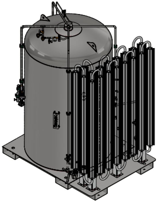
Figure 4.
Cryogenic tank of 3000 L.
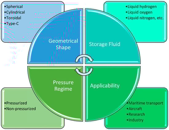
Figure 5.
Classification criteria for cryogenic tanks.
From the perspective of cryogenic tank types, classification is based on several factors, including geometrical shape, pressure regime, intended application, and the nature of the stored fluid. Each structural configuration addresses specific requirements regarding thermomechanical behavior, insulation efficiency, and adaptability to the host system [44].
One of the most efficient geometrical shapes is the spherical configuration. Due to radial symmetry, spherical tanks distribute mechanical stresses uniformly and minimize the surface area in contact with the external environment, which significantly reduces losses through conduction and radiation [44]. This type is frequently used in the aerospace sector, where low mass and thermal conservation are critical for propulsion system performance [48].
In terrestrial or maritime applications, the cylindrical shape is predominant. Such tanks are easier to manufacture, provide good integration into rectangular spaces, and can be mounted either horizontally or vertically, depending on installation architecture [47].
Pressurized cylindrical variants are often employed in transportable containers or industrial testing equipment, where robustness and simplicity are major advantages [46].
Toroidal configurations also exist, typically used in applications where peripheral space utilization or integration around other equipment is required. While they provide compact geometry, they pose challenges related to temperature distribution and fabrication complexity [48].
A particular case is represented by Type-C tanks, extensively employed in maritime transport of liquid hydrogen. These structures are built from cryogenically compatible materials, capable of withstanding high internal pressures, and equipped with both active and passive insulation systems, in compliance with IMO international standards [43]. Their design is optimized for autonomous operation without continuous venting and for integration into large-scale mobile systems.
Depending on the mode of operation, tanks may be pressurized, where the liquid is maintained above atmospheric pressure to reduce vaporization rates and enable controlled extraction [56]. Alternatively, non-pressurized tanks are used, particularly in laboratory experiments or temporary applications, where boil-off is acceptable or even necessary to maintain constant pressure [49].
The choice of tank type is also closely linked to the nature of the cryogenic fluid. For example, liquid hydrogen requires materials with low diffusivity, capable of resisting embrittlement and limiting atomic permeability [1]. Internal configurations are further adapted to prevent thermal stratification and ensure complete drainage, including under microgravity conditions [50].
Advanced applications, particularly in hydrogen-powered aviation, demand customized configurations such as wing-integrated tanks or modular models designed to optimize the center of gravity and mass distribution [45]. In such cases, aerodynamic, structural, and thermal requirements are combined into a single multifunctional cryogenic structure [57]. Thus, the typology of a cryogenic tank is not merely a geometric choice but an engineering decision that involves balancing multiple parameters: thermal stability, structural safety, usable volume, and compatibility with the target application.
Regarding tank design, structural engineering requires a multidisciplinary approach, where structural mechanics, heat transfer, material compatibility, and operational requirements interact. Structural elements must ensure tank integrity under extremely low temperatures, internal pressure variations, and severe environmental factors, without compromising the overall mass of the system [44].
A fundamental design principle is the functional separation between the load-bearing structure and the insulation layers. In classical configurations, the inner liner is made of metallic or cryogenic composite materials, while the outer shell is designed to withstand mechanical and vibrational loads [45]. This approach allows for optimization of each layer according to its function: mechanical resistance, thermal insulation, or environmental protection [1].
The materials employed must withstand significant thermal contractions without cracking, delamination, or loss of ductility. For example, aluminum alloys and austenitic stainless steels are widely used due to their stable behavior at temperatures below 100 K [46]. In aerospace applications, carbon-fiber-reinforced epoxy composites are increasingly employed to reduce tank mass while maintaining mechanical performance [48].
A finite element–based representation of a cryogenic tank geometry, including the definition of material properties for structural analysis, is illustrated in Figure 6.
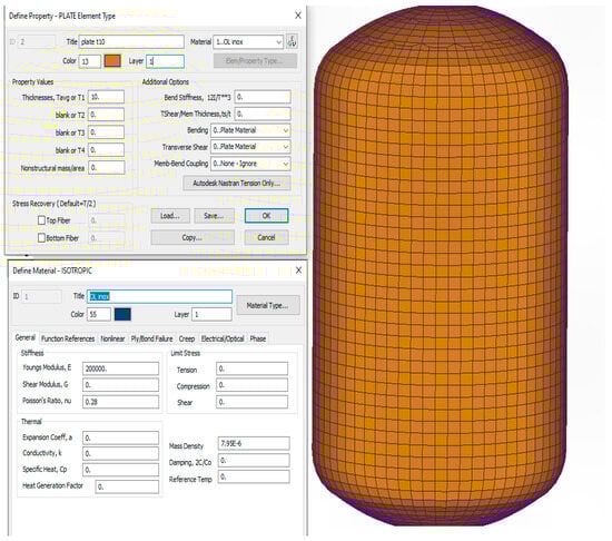
Figure 6.
Finite element (FEM) geometric model of a cryogenic tank, including material property definition for structural analysis.
Geometric design must minimize areas of stress concentration and ensure a uniform distribution of loads generated by internal pressure and inertia. Particularly in applications such as launch vehicles or stratospheric balloons, rapid pressure variations and high accelerations can induce significant dynamic stresses [54]. Therefore, bulkheads, stiffening ribs, and cryogenic suspensions are strategically integrated to absorb these loads [49].
The internal pressure fields resulting from typical operating conditions and structural loading scenarios in cryogenic tanks are illustrated in Figure 7.
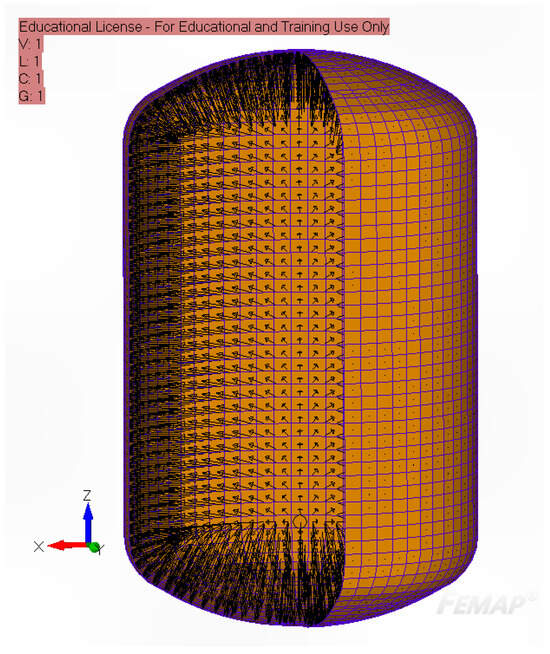
Figure 7.
Representative internal pressure distribution within a cryogenic tank under typical operating conditions.
A key challenge in structural design is the integration of the cryogenic tank into the overall system. In aerospace vehicles, integration must account for the center of gravity, fuselage geometry, and the routing of auxiliary systems such as transfer lines, cryogenic valves, and sensors [57]. Recent studies propose the use of adapted shapes, such as elliptical casings or segmented structures, to maximize interior space efficiency and ensure seamless integration with wings or fuselage [45].
Operational pressure is another decisive factor in design. Self-pressurizing tanks require internal reinforcements and safety valves, while passive systems—often employed in fundamental research or high-altitude scientific balloons—must completely minimize boil-off through advanced insulation performance [55].
Numerical modeling plays a central role in structural design. Finite element analysis (FEA) is employed to evaluate stress distributions, cryogenic deformations, and thermal cycling behavior [47]. Computational fluid dynamics (CFD) simulations are frequently integrated to assess fluid behavior inside the tank under transient regimes, supporting optimization of the tank geometry and the placement of internal components such as baffles or intake tubes [50].
Efficient integration of a cryogenic tank requires more than geometric compatibility; it must ensure functional interaction with all subsystems, including thermal control, venting, safety, and automation. A successful design must balance these requirements without compromising overall mass, performance, or safety [51].
Beyond structural integrity, thermal insulation, and operational safety, it is also essential to examine the practical implications of these considerations. Understanding how tanks are employed in real-world applications provides the necessary context for evaluating design efficiency and operational performance. Thus, the functional purpose of cryogenic tanks and their utilization across industrial and technological domains underscores the interdependence between practical requirements and adopted engineering solutions.
Cryogenic tanks are essential components in numerous industrial, scientific, and commercial applications, ensuring the safe storage and handling of liquids at very low temperatures, typically below 120 K. They enable the use of liquefied gases such as hydrogen, helium, nitrogen, oxygen, and methane in liquid form, ensuring high energy density and efficient preservation in mass- and volume-sensitive systems [44].
In the maritime sector, Type-C tanks are extensively used for transporting LH2 under high pressure, designed according to IMO codes and optimized to minimize mass losses due to boil-off. They are vital for future hydrogen-powered vessels, serving as both storage and continuous fueling systems for zero-emission propulsion [44]. In this context, thermal performance and structural integrity are critical during long-duration voyages [48].
In aerospace applications, cryogenic tanks are used in rockets employing LOX/LH2 propellants, stratospheric balloons, and scientific instruments requiring ultra-low temperatures. These systems must withstand extreme accelerations, pressure variations, deep vacuum, and rapid thermal cycling [54]. Furthermore, the design must minimize thermal losses without increasing overall mass, necessitating sophisticated insulation and structural integration solutions [55].
In the energy sector, cryogenic tanks are indispensable for the production, transport, and storage of green hydrogen. Within liquid H2 supply chains, they act as buffers between electrolysis and electrochemical conversion in fuel cells, requiring full compatibility with intermittent operation and rapid load/unload cycles [45].
Medical and scientific applications include cryopreservation of biological tissues and operation of imaging equipment (e.g., MRI), where liquid helium is used for cooling superconductors [52]. In such cases, tanks must operate with extremely low boil-off levels, while monitoring systems must allow rapid detection of any losses or malfunctions.
Given the wide range of applications—from liquid hydrogen transport in the maritime sector to aerospace, medical, and energy systems—it becomes clear that tank performance depends not only on geometry and construction materials but also on the ability to minimize thermal losses. In this context, thermal insulation technologies acquire strategic importance, directly influencing energy efficiency, operational safety, and the long-term sustainability of cryogenic systems. Modern insulation solutions analyze the underlying physical principles, materials employed, and selection criteria according to the target application.
Thermal insulation represents a critical factor in the functional efficiency of cryogenic tanks, directly affecting the boil-off rate, structural integrity, and overall operational cost. Technologies are selected according to the application, environmental conditions, and tank geometry [1].
The most effective solution is vacuum insulation combined with multilayer reflective foils (MLI-multilayer insulation). This technology relies on a vacuum space between the inner tank and the outer shell, interspersed with dozens of thin reflective layers, such as aluminum-coated Mylar [53]. This configuration simultaneously reduces all three modes of heat transfer: conduction, convection, and radiation [48].
Experimental results highlight the dominant contribution of heat transfer through the lateral walls of the tank, which, under specific operational configurations, can account for more than 80% of the total heat input to the liquid phase, thereby emphasizing the critical importance of optimizing thermal insulation systems in cryogenic applications [30].
Recent investigations have provided detailed quantitative assessments of multilayer insulation (MLI) systems used in cryogenic tanks, highlighting both their high thermal efficiency under nominal conditions and their limitations under extreme scenarios. Comparative analyses of MLI configurations for liquid hydrogen vessels indicate that these systems exhibit very low density and minimal volume occupation, making them particularly suitable for applications where mass and space constraints are critical, such as transport and aerospace systems [58]. Under high-vacuum operating conditions, optimized MLI layouts can reduce the effective heat flux entering the tank to the order of a few watts per square meter, resulting in boil-off rates typically below 1% per day in liquid hydrogen storage applications [58].
However, recent modeling and safety-oriented studies demonstrate that the thermal performance of MLI systems can deteriorate rapidly when exposed to accidental external fire scenarios. Elevated external temperatures significantly compromise the reflective layers, leading to a sharp increase in heat ingress and accelerated pressurization of the cryogenic vessel [59]. Comparative fire-scenario assessments further show that, for external shell temperatures exceeding approximately 1160 K, severe degradation of the insulation system may occur within tens of minutes, potentially resulting in structural failure regardless of the specific reflective material employed [60]. These findings emphasize that, while MLI systems are highly effective for minimizing heat losses under normal cryogenic operation, their contribution to overall tank safety is strongly dependent on environmental exposure conditions and must therefore be considered in the context of fire-safety regulations and design standards [58,59,60].
From a regulatory perspective, the fire resistance and degradation behavior of thermal insulation systems used in cryogenic tanks must comply with international safety frameworks such as the IMO and the ASME Boiler and Pressure Vessel Code, which require insulation and containment systems to limit heat ingress, prevent catastrophic pressure rise, and maintain structural integrity under accidental fire and extreme thermal exposure conditions [44,45,46,47,48].
In commercial and industrial applications, where cost-effectiveness and manufacturability are priorities, porous or composite insulation materials are commonly employed, such as perlite, cryogenic polyurethane foams, or aerogels. These materials exhibit low thermal conductivity but are more sensitive to thermal cycling and may suffer from compaction or vapor absorption [47]. However, rigid foams have the advantage of being easily applied to complex geometries and can simultaneously serve as a protective mechanical layer.
The structural arrangement of the vacuum insulation chamber separating the inner and outer shells of a cryogenic tank is illustrated in Figure 8.
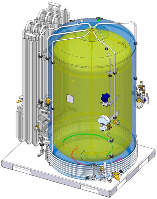
Figure 8.
The vacuum insulation chamber between the inner and outer shells of the cryogenic tank.
In advanced systems, insulation is optimized using CFD and heat transfer models to evaluate real-time behavior. For example, simulations demonstrate how layer thickness, tank geometry, and MLI orientation significantly influence overall performance [52]. Furthermore, the composition of residual gas in the evacuated space affects convective transfer and must be carefully controlled [52].
An emerging trend is the integration of active insulation, where sensors and piezoelectric or thermoelectric cooling elements locally adjust temperatures in critical regions of the tank. Although still experimental, these technologies show strong potential for space and defense applications [55].
The correct selection of the insulation system is a decisive factor for overall performance, safety, and durability, requiring a comprehensive assessment of the operating environment, pressure regimes, and duty cycles.
Safe operation of cryogenic tanks demands the integration of highly precise monitoring and control systems capable of functioning reliably under severe temperature and pressure conditions. These systems ensure real-time supervision of critical parameters and help prevent hazardous phenomena such as overpressure, localized boiling, or massive fluid losses [51].
Temperature sensors are typically fabricated from semiconductor materials suitable for operation below 77 K, such as doped silicon, germanium, or calibrated thermoelectric alloys. They are positioned strategically near the tank bottom, at the liquid level, and in venting regions [52]. Measured values are fed into a data acquisition (DAQ) system that runs adaptive control algorithms to stabilize internal conditions.
Control systems include safety valves, regulation valves, electromechanical actuators, and programmable logic controllers (PLCs) that automatically manage pressure and temperature. If boil-off exceeds a critical threshold, the systems can either vent vapor in a controlled manner or activate a recirculation mechanism to maintain internal equilibrium [53].
In aeronautical and space applications, control systems are even more sophisticated: sensors communicate through redundant networks, with encrypted telemetry transmissions. Data are processed on-board or ground-side, and corrective actions are executed autonomously. For example, in stratospheric balloon tanks, thermal losses are dynamically corrected by adjusting internal pressure or modifying orientation relative to solar radiation [54].
A particularly critical aspect is liquid-level monitoring, which may be achieved using capacitive or ultrasonic sensors, or through cryogenic-specific methods such as differential density detection. These systems enable accurate estimation of remaining fluid volume and trigger alarms in the event of leaks or uncontrolled evaporation [47].
Integration of all these components into a coherent platform requires electromechanical compatibility, frost protection, redundancy, and shock resistance—especially in mobile or spaceborne applications [45]. New generations of cryogenic tanks already incorporate self-diagnosis, IoT connectivity, and predictive control powered by machine learning.
As the energy transition accelerates, cryogenic tanks are becoming central elements in sustainable mobility systems, space exploration, and large-scale energy storage. Advanced applications require integration into complex architectures with strict demands for weight, safety, durability, and thermal efficiency [45].
In the aeronautical sector, recent research focuses on hydrogen-fueled aircraft. Integrating cryogenic tanks into the fuselage or wings requires balancing volume, stability, mass distribution, and minimizing boil-off [48]. These tanks must be structurally compatible with the aircraft, resistant to vibrations and severe thermal cycles, and geometrically optimized to reduce aerodynamic drag [57].
In space missions, cryogenic tanks are used not only for propulsion (liquid oxygen and hydrogen) but also in satellite thermal control systems and scientific instruments. Stratospheric balloons, such as those employed in SPIDER or TAURUS projects, demand extremely well-insulated tanks capable of functioning without active cooling for weeks at altitudes above 35 km [55]. Under such conditions, passive insulation systems and uniform distribution of the cryogenic load are critical [54].
In fundamental research, cryogenic tanks are indispensable in particle accelerators, cosmic radiation detection chambers, and quantum physics experiments. Cooling components to temperatures close to absolute zero allows for precise control of thermal fluctuations and unprecedented accuracy in measurements [52].
Emerging applications also include hydrogen-based electric propulsion systems for heavy vehicles, industrial drones, and high-speed trains. In these cases, tanks must be modular, shock-resistant, easy to maintain, and compatible with automated refueling systems [47].
With the rapid expansion of cryogenic tank applications—from hydrogen-powered aircraft to high-precision scientific instrumentation and autonomous energy storage systems—the need for a robust regulatory framework ensuring safety, reliability, and technological compatibility has become increasingly evident. Implementation of these systems in critical contexts requires compliance with complex international standards tailored to extreme operating conditions and application-specific requirements.
The safe operation of cryogenic tanks is governed by a robust set of international standards adapted to the specifics of each application. These regulations define detailed requirements for materials, pressure testing, structural design, failure protection, and thermal loss control [44].
In the maritime sector, the International Maritime Organization (IMO) mandates compliance with the IGC Code for the transport of liquefied gases, including liquid hydrogen. This code specifies requirements for wall thickness, insulation type, redundancy of safety systems, and pressure maintenance capabilities in emergency scenarios [44,45,46,47,48].
For terrestrial applications, the ASME Boiler and Pressure Vessel Code (Section VIII) defines the conditions for design, testing, and certification of pressure vessels. ISO 21014 regulates methods for assessing thermal losses, while ISO 20421-1 specifies requirements for fixed cryogenic tanks [50].
In aerospace applications, agencies such as NASA, ESA, and ECSS (European Cooperation for Space Standardization) enforce much stricter requirements regarding vibration behavior, thermal tolerances, vacuum material compatibility, and long-term reliability. For instance, insulating materials must be tested for degradation under thermal cycling, UV radiation, and microgravity effects [54].
Recent regulations also integrate sustainability principles, including carbon footprint assessment, component recyclability, and safety in case of failure. Provisions also include material traceability, non-destructive weld testing, and periodic calibration of sensors [53].
The structural integrity and regulatory compliance of cryogenic tanks are further ensured through rigorous inspection and quality-control procedures applied to critical components, as illustrated in Figure 9.
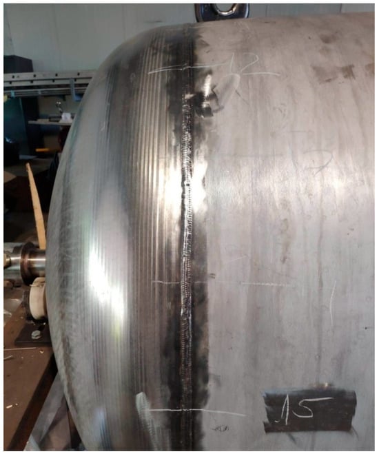
Figure 9.
Weld joint between the nozzle and the upper head of an inner pressure vessel, inspected by NDT methods (VT, US).
An important component is the harmonization of international standards to enable the interoperability of equipment across different regions and industries. This facilitates the development of a global liquid hydrogen ecosystem, in which cryogenic tanks play a central role [45].
3.2. Materials Used
Cryogenic tanks play a vital role across numerous industries, ranging from the transport and storage of liquefied natural gas (LNG) to aerospace and medical applications [61]. These vessels must safely handle liquids at extremely low temperatures, such as liquid hydrogen at 20 K, liquid nitrogen at 77 K, or liquid oxygen at 90 K, which imposes exceptional requirements on the materials used in their construction [33]. The correct selection of materials is not only a matter of mechanical strength but also of thermal stability, resistance to corrosion, embrittlement, and durability under severe cyclic conditions [62]. The impact of this selection on the overall tank performance is crucial for operational safety and long-term cost optimization [63,64].
Low temperatures affect not only the intrinsic properties of materials but also the interactions between components of composite structures or between different material layers, leading to residual stresses and potential structural defects [65]. In addition, thermal transfer through the tank walls must be minimized to reduce unwanted evaporation and, consequently, economic losses and safety risks associated with gas accumulation [66]. In this context, composite materials, especially alloyed metals, and high-performance insulators constitute the technological pillars of modern cryogenic tank design [67].
Ensuring the reliable and safe operation of cryogenic tanks under extreme temperature and loading conditions requires the careful selection of constituent materials as a key element of the design process. The physical and mechanical properties of these materials at cryogenic temperatures directly influence structural performance, long-term integrity, and compliance with international standards.
The mechanical properties of materials at cryogenic temperatures are influenced by microstructural changes [64] and by embrittlement phenomena occurring at the atomic and microscopic levels [68]. Most metals exhibit an increase in yield strength and tensile strength as temperature decreases, owing to the reduced mobility of dislocations in the crystalline lattice [68,69]. However, this trend is accompanied by a reduction in ductility and toughness, a phenomenon known as low-temperature embrittlement, which can result in brittle fractures that are hazardous in service [64].
Recent studies have demonstrated that cryogenic embrittlement is not an intrinsic limitation of steels but can be effectively mitigated through advanced microstructural design strategies. Recent experimental advances indicate that cryogenic mechanical performance can be substantially enhanced through microstructural engineering rather than through extensive alloying. Xu et al. reported that a heterostructured low-carbon micro-alloyed steel achieved an impact toughness of approximately 200 J/cm2 at 77 K, which is about 24 times higher than that of conventional coarse-grained steels and nearly three times higher than that of ultrafine-grained microstructures [70]. Instrumented Charpy impact tests further revealed an absorbed energy of 79.5 J at 77 K, confirming the exceptional resistance to crack initiation and propagation under cryogenic conditions. Importantly, these mechanical properties were obtained without significant nickel alloying and were shown to meet performance requirements comparable to those of conventional 9% Ni cryogenic steels, highlighting a cost-effective and sustainable pathway for the development of next-generation cryogenic structural materials [70].
In parallel with microstructural engineering approaches, recent alloy development studies have reported promising cryogenic performance, although these materials are still at an early research stage.
Recent literature highlights alloy design as a highly effective strategy for achieving superior cryogenic performance without relying on heavy nickel alloying. In this regard, Shang et al. (2025) [71] demonstrated that a high-manganese austenitic steel maintains exceptional impact resistance at extremely low temperatures. Charpy impact testing revealed absorbed energy values of approximately 116 J at −196 °C and 80 J at −269 °C, confirming robust fracture resistance at both liquid nitrogen and liquid helium temperatures. The sustained cryogenic toughness was attributed to the activation of complementary deformation mechanisms, including mechanical twinning, stacking fault formation, and ε-martensite transformation, which collectively inhibit crack initiation and propagation. These findings position high-Mn austenitic steels as promising candidates for next-generation cryogenic structures, offering a favorable balance between mechanical performance, alloying efficiency, and industrial scalability [71,72].
Austenitic stainless steels, particularly type 316L, are widely recognized for their ability to retain favorable mechanical properties and high ductility even at cryogenic temperatures, due to the stability of their crystalline structure and the high nickel content that stabilizes the austenitic phase [64]. Experimental tests have demonstrated significant increases in mechanical strength at 77 K, but also a reduced plastic deformation capacity compared to room temperature [64].
To provide a comparative perspective on the mechanical response of materials commonly used for cryogenic tanks, Figure 10 and Figure 11 illustrate the variation in the yield strength and tensile strength of 316L austenitic stainless steel, S275 structural carbon steel, and carbon fiber reinforced polymer (CFRP) at room temperature (20 °C) and cryogenic temperature (−196 °C).
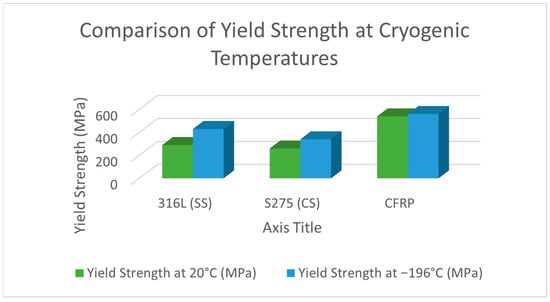
Figure 10.
Comparison of yield strength at room temperature (20 °C) and cryogenic temperature (−196 °C) for selected cryogenic tank materials: 316L (SS) austenitic stainless steel, S275 (CS) structural carbon steel (EN 10025), and carbon fiber reinforced polymer (CFRP).
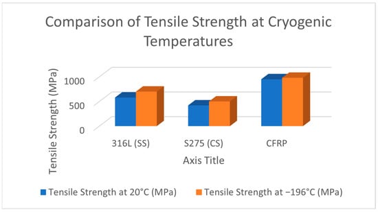
Figure 11.
Comparison of tensile strength at room temperature (20 °C) and cryogenic temperature (−196 °C) for selected cryogenic tank materials: 316L (SS) austenitic stainless steel, S275 (CS) structural carbon steel (EN 10025), and carbon fiber reinforced polymer (CFRP).
In the case of carbon-fiber-based composites, mechanical resistance at low temperatures is complex, owing to the thermal mismatch between the fibers and the polymer matrix, which can induce internal stresses and microcracks [62]. Recent research indicates that cyanate ester-based matrices exhibit superior performance in terms of cryogenic microcracking resistance compared with conventional epoxy resins [67]. Thus, the polymer matrix represents the critical factor for the durability of composites in cryogenic environments [65].
The structural behavior of materials at cryogenic temperatures must be correlated with their ability to limit heat flux from the surrounding environment. Energy losses through conduction and radiation may compromise the thermal stability of the system, which requires particular attention to the thermal conductivity of materials used in tank construction.
Thermal conductivity constitutes an essential factor in the design of cryogenic tanks, as heat transfer from the ambient environment to the cryogenic liquid leads to evaporation and energy losses [66,73]. Metallic materials generally exhibit relatively high thermal conductivities; for instance, stainless steel 316L has a conductivity of about 16 W/m·K, while carbon steel can reach values of up to 45 W/m·K [64]. This necessitates the use of high-performance insulating materials in combination with the metallic structure [74].
Multilayer insulation (MLI), consisting of multiple layers of reflective foil interleaved with dielectric materials, reduces heat transfer through radiation and conduction to minimal values on the order of a few mW/m·K, making it the standard in high-performance space and cryogenic applications [67,74]. Additionally, evacuated foam insulations and expanded perlite are employed for the thermal protection of tanks and associated components, providing a balance between performance and cost [66].
Low-temperature embrittlement is caused by changes in the crystalline structure [64] and phenomena such as phase transformations, precipitation, and stress concentration in material defects. Carbon steels and low-nickel alloys are more susceptible to embrittlement, which is why austenitic stainless steels or special alloys are preferred in the design of cryogenic tanks [69].
For composites, embrittlement is mainly associated with microcracking of the polymer matrix [62], which compromises the fiber–matrix bond and, implicitly, the overall mechanical strength [65]. Recent studies show that cyanate ester matrices exhibit increased resistance to microcracking compared with epoxies, due to their rigid chemical structure and superior thermal properties [67].
The contrasting deformation and damage mechanisms that govern the cryogenic mechanical behavior of steels and composite materials—namely dislocation activity in metals and microcrack initiation in polymer-matrix composites—are illustrated in Figure 12.
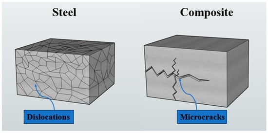
Figure 12.
Schematic comparison of deformation and damage mechanisms in steel and composite materials, illustrating dislocation activity in steel and microcrack initiation in composite structures under low-temperature conditions.
Beyond their influence on heat transfer, cryogenic temperatures also induce profound structural effects in the materials employed, promoting embrittlement mechanisms that may compromise the mechanical integrity of the system. Cryogenic tanks are exposed to humid environments and may contain impurities that accelerate corrosion processes [64], particularly at welds and material interfaces [69]. Stainless steels provide excellent protection owing to the passive chromium oxide layer formed on their surface, making them the preferred choice in humid cryogenic conditions [64].
Composite materials, due to their organic nature and chemical composition, exhibit higher resistance to chemical corrosion [62], yet the polymer matrix may degrade in the presence of aggressive chemical agents. Consequently, chemical protection and appropriate matrix selection are essential for ensuring long-term durability [66].
The adaptation of materials to cryogenic demands requires not only mechanical and chemical resistance but also the ability to retain their shape and thermal behavior under extreme temperature variations. Dimensional stability, therefore, becomes a critical criterion in preventing structural defects and maintaining the functional performance of the tank.
The coefficient of thermal expansion of materials is critical in cryogenic tank design to prevent the development of internal stresses resulting from differential contraction between components [64]. Stainless steels possess relatively low coefficients, favoring dimensional stability, whereas the larger mismatches encountered in composites may induce stresses that promote microcracking [62].
Thermal properties such as specific heat capacity and thermal conductivity strongly influence the tank’s thermal behavior in operation, directly impacting boil-off rates and the energy required to maintain optimal storage temperature [67].
The thermal properties of representative structural materials used in cryogenic tanks, together with their qualitative performance, are summarized in Table 5.
Table 5.
Thermal conductivity and qualitative cryogenic performance of representative structural materials.
Materials must withstand high mechanical loads, including impacts and repeated thermal cycles, while maintaining ductility and toughness at low temperatures. In addition, thermal expansion coefficients must be compatible across different structural components to prevent internal stresses and cracking [64].
Corrosion resistance is essential, particularly for components directly exposed to aggressive cryogenic environments, including water vapor and impurities [69]. Chemical compatibility with the stored liquid and the operating environment must also be guaranteed to avoid material degradation and contamination of the cryogenic fluid [64].
Cryogenic tanks are subject to repeated freeze–thaw cycles that can induce thermal fatigue and microcracking [64]. Therefore, the selected materials must demonstrate high durability to ensure long-term functionality without the occurrence of critical defects.
Finally, materials must allow for efficient processing, welding, and assembly under strict quality control [64], facilitating serial production and ensuring overall structural integrity [69].
The assessment of material durability and structural integrity in cryogenic tanks relies on rigorous inspection techniques, particularly for welded joints and critical components, as illustrated in Figure 13.
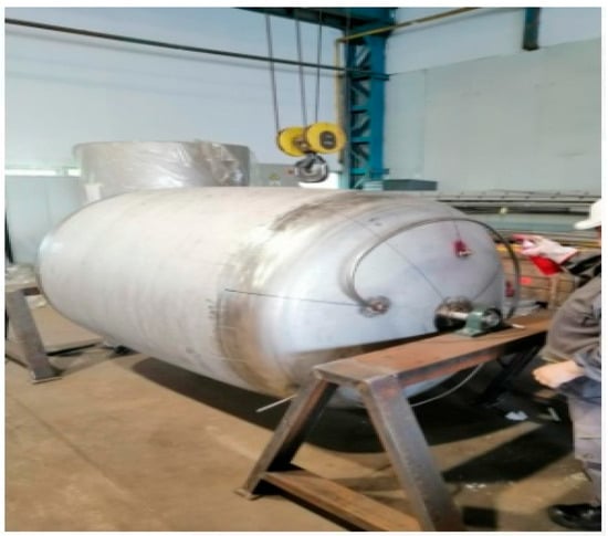
Figure 13.
Non-destructive testing of welds using penetrant liquids.
Several studies have demonstrated the applicability of material combinations in cryogenic tanks for optimizing overall performance.
For instance, the integration of austenitic stainless steels with external composite layers has enabled significant reductions in weight [75] and thermal losses in LNG tanks, thereby extending service life and lowering operational costs [76].
In the aerospace industry, the use of multilayer insulation in combination with specialized metallic structures has ensured the reliable performance of liquid hydrogen storage systems under microgravity conditions [74] and extreme thermal environments [65].
Another example is the application of 9% nickel steel in cryogenic rocket tanks, where high mechanical performance and resistance to embrittlement are critical, despite the increased costs and processing complexity [64].
Metals represent the traditional and most widely used category for the construction of cryogenic tanks, owing to their high mechanical strength and well-documented behavior at low temperatures. Among the most frequently employed are austenitic stainless steels, carbon steels, and aluminum alloys [76].
From a system-level perspective, material selection for low-temperature storage tanks directly influences both operational safety and thermal efficiency. Austenitic stainless steels exhibit high fracture toughness, stable ductility at cryogenic temperatures, and strong corrosion resistance, which significantly reduce the risk of brittle failure and enhance structural safety under extreme service conditions [64,69]. Aluminum alloys, while mechanically less strong than steel, retain adequate ductility at low temperatures and provide substantial weight reduction, contributing to improved system efficiency, particularly in aerospace and transport applications; however, their relatively high thermal conductivity may increase heat ingress if not combined with effective insulation systems [64,66]. Composite materials further improve weight efficiency and thermal performance, yet their long-term safety is strongly governed by the behavior of the polymer matrix, as differential thermal contraction between fibers and matrix can induce microcracking and compromise structural integrity under cryogenic cycling [62,65]. Consequently, the selection of materials for cryogenic storage tanks involves a complex trade-off between mechanical reliability, thermal insulation efficiency, and structural weight, emphasizing the importance of a holistic, system-level design approach [67].
Austenitic stainless steels, particularly grade 316L, are preferred due to the stability of their crystalline structure, high corrosion resistance, and ability to maintain ductility at temperatures below 77 K [69]. The nickel content ensures the retention of the austenitic phase and reduces the risk of embrittlement, thereby ensuring safe operational behavior [76]. Mechanical tests have demonstrated an increase in tensile strength and hardness of 316L steel as temperature decreases, with the yield strength rising considerably, enabling the material to sustain high loads without permanent deformation. Xu et al. reported up to a 30–40% increase in tensile strength at 77 K compared to room temperature, while ductility decreased moderately but still provided sufficient plasticity to prevent brittle fracture. In addition, 316L steel exhibits favorable tribological behavior and a low friction coefficient under cryogenic conditions, enhancing durability in components subjected to dynamic stresses [64].
From a processing perspective, austenitic stainless steels require advanced welding technologies and strict microstructural control to avoid intergranular precipitations and microcracks that could compromise structural integrity under cryogenic environments [69].
Carbon steels, such as S355, are often used in non-critical structural components of cryogenic tanks due to their low cost and good room-temperature mechanical properties. However, at low temperatures, they experience a significant loss of ductility and toughness, undergoing embrittlement phenomena that limit their use in severe cryogenic environments. Ductile-to-brittle transition occurs abruptly around 223 K to 173 K, depending on chemical composition and heat treatment, mainly due to martensitic transformations and intermetallic precipitations [69]. Although alloying with nickel, chromium, or manganese can improve their cryogenic behavior, such steels are more expensive and demand advanced processing techniques. In practice, carbon steels are employed for external or secondary structural parts not in direct contact with cryogens, often combined with protective or insulating layers [76].
Aluminum and its alloys are valued for their low density and good thermal conductivity, making them attractive for aerospace and maritime applications where weight is critical. Although mechanically weaker than steels, aluminum retains good performance at low temperatures. Alloys such as 6061-T6 strike a balance between strength and reduced thermal conductivity, while maintaining cryogenic stability. Mechanical properties improve at low temperatures, with yield strength and hardness increasing by more than 30–50%, while ductility remains sufficient to prevent brittle failure. However, its higher coefficient of thermal expansion compared to steels may lead to internal stresses in hybrid structures [64].
Nickel-based alloys, notably 9% Ni steel, have been developed for advanced cryogenic applications such as LNG tanks and rocket fuel reservoirs, offering exceptional strength, ductility, and dimensional stability down to 4 K [64]. Despite their outstanding performance, their processing is complex and costly, requiring specialized welding and heat treatment [69].
Titanium and its alloys are used in selected critical components due to their high strength-to-weight ratio and excellent chemical resistance. However, their high costs and processing challenges limit widespread adoption [69]. Similarly, oxygen-free copper and rare metals are employed in highly specialized cryogenic applications requiring exceptional purity and corrosion resistance [76].
Beyond metals, recent research emphasizes the use of composite materials and biocomposites in secondary tank structures, insulation panels, and lightweight internal elements. Composites, consisting of reinforcing fibers (e.g., carbon, glass, aramid) embedded in a polymeric matrix, offer superior strength-to-weight ratios and excellent cryogenic performance [62,65]. However, polymeric matrices are prone to microcracking due to differential thermal contraction between fibers and matrix, which can lead to delamination [65]. Cyanate ester resins are increasingly investigated as alternatives to conventional epoxies, offering improved cryogenic crack resistance and thermal compatibility [67].
Compared to metals, composites enable 20–40% weight reduction in cryogenic tanks [77,78], while advanced molding techniques reduce assembly complexity and production costs [79,80]. Emerging research explores nanomaterial integration (e.g., carbon nanotubes) for enhanced structural and thermal properties [65].
Thermal insulation materials are indispensable for limiting heat transfer between the cryogen and the environment. Expanded perlite, rigid polyurethane (PUR) foams, multilayer insulation (MLI), and vacuum-insulated foams (VIPs) are the main categories used. MLI, consisting of multiple reflective layers separated by dielectric spacers, provides the highest thermal efficiency (1–5 mW/m·K) and is standard in space and advanced cryogenic applications [74]. Perlite is cost-effective and widely applied in large-scale LNG tanks, while VIPs provide superior performance but remain restricted to specialized, high-cost systems [67].
The thermal insulation materials commonly employed in cryogenic tanks, together with their characteristic performance metrics, operating conditions, and typical applications, are summarized in Table 6.
Table 6.
Thermal insulation performance metrics for representative cryogenic tank insulation materials.
Values are indicative and strongly dependent on boundary conditions. For perlite and vacuum-insulated systems, reported values represent effective thermal conductivity (k_eff). For MLI, performance should be reported as heat flux (q″) under specified vacuum level, number of layers, and boundary temperatures.
Polymeric foams such as PUR/PIR are widely used for cryogenic insulation of tanks in space launchers operating with liquid hydrogen (LH2) and liquid oxygen (LOX). These materials combine low thermal conductivity at cryogenic temperatures, low density, dimensional stability, and mechanical strength suitable for the specific stresses of the aerospace environment. In contrast to insulation systems based solely on vacuum, polymer foams maintain performance under ground-operating conditions and during the ascent phase, where thermal and mechanical stresses are critical [81,82].
In aerospace applications, cryogenic insulation is mainly based on multilayer insulation (MLI) and polymer foams. Although MLI is effective in vacuum, its performance is reduced under atmospheric conditions, where PUR foams offer low thermal conductivity, low moisture permeability, and dimensional stability, suitable for external insulation of cryogenic tanks (ETI) and for maintaining adhesion to metal structures [81].
Spray-applied polyurethane foams have been used since the Saturn V and Space Shuttle programs, the method allowing uniform coating of metal surfaces with complex geometries and obtaining effective adhesion to aluminum substrates. Modern PUR formulations intended for cryogenic applications present experimentally validated thermal and mechanical performances, resistance to cryogenic shock, and stability to exposure to UV radiation and accelerated aging processes [81,83].
Rigid polyurethane (PUR/PIR) foams represent one of the most widely used cryogenic insulation materials due to their balanced thermal and mechanical performance, spray-on applicability, and stable behaviour under cryogenic thermal cycling. Experimental studies report thermal conductivity values in the range of approximately 0.017–0.021 W/m·K for rigid PUR foams, confirming their suitability for LNG and liquid hydrogen storage and aerospace cryogenic tank insulation [84,85].
Recent trends in cryogenic PUR insulation focus on the development of environmentally friendly formulations based on fourth-generation physical blowing agents with low global warming potential. Studies show that blowing agents such as HFO-1233zd(E) and HFO-1336mzz(Z) enable reduced thermal conductivity while maintaining comparable ageing behaviour and mechanical integrity at cryogenic temperatures [84].
Outside the aerospace field, rigid polyurethane foams are also used for cryogenic insulation of liquefied gas storage and transportation systems, LNG ships, and onshore liquid hydrogen tanks, confirming the transferability and reliability of these materials in large-scale cryogenic applications [81].
Beyond the intrinsic properties of the materials, the overall thermal efficiency of cryogenic insulation systems is strongly governed by configuration-dependent factors, including layer placement, surface emissivity, and proximity to the cold wall boundary. Recent numerical and experimental investigations demonstrate that the integration of a single intermediate insulation layer made of ultra-radiopure, low-emissivity materials and positioned as close as possible to the cold wall can reduce the total radiative heat load by approximately 40–60% [85]. This substantial attenuation of heat penetration translates directly into a measurable decrease in the evaporation rate of the cryogenic liquid, thereby increasing thermal stability and extending operational hold times in cryogenic storage systems [86,87,88].
The configuration and location of multilayer insulation systems used to limit heat transfer in cryogenic vessels are schematically illustrated in Figure 14.
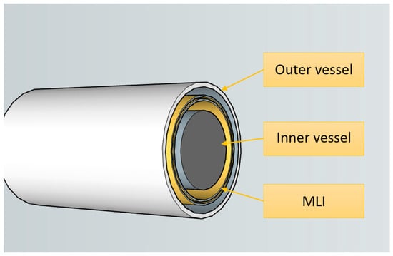
Figure 14.
Multilayer insulation (MLI) for cryogenic vessels.
Closed-cell foams and vacuum insulated panels (VIPs) provide the highest level of mechanical and thermal insulation, with thermal conductivities ranging from 5 to 20 mW/m·K [66] and densities between 30 and 100 kg/m3. These materials are particularly employed in applications with stringent thermal performance requirements and limited space; however, the high costs and fragility of VIPs restrict their widespread use [67].
The performance of insulating materials is not determined solely by their intrinsic properties, but also by a range of external conditions and operational parameters that can significantly influence the thermal behavior of the entire assembly. Thermal efficiency may be affected by multiple variables such as the nature and microstructure of the material, temperature and pressure conditions, degree of compaction, long-term stability, and the method of application or integration into the system. Furthermore, the presence of vapors, temperature fluctuations, and environmental humidity can decrease insulation efficiency through mechanisms such as absorption or the formation of thermal bridges.
Insulation performance may deteriorate under variable temperature and pressure conditions, including repeated thermal cycles that can induce both mechanical and thermal degradation. A rigorous assessment of insulating materials under real operational conditions is therefore necessary, including numerical simulations and accelerated testing [74].
The efficiency of insulation depends directly on the thickness and uniformity of the insulating layer, as well as on the way it is arranged within the tank structure. Optimizing these parameters requires a careful balance between thermal performance, cost, and weight—critical aspects particularly in the aerospace industry [74].
Local regions with abnormally low temperatures, referred to as cold spots, can result in thermal stress concentrations and increased heat transfer, thereby reducing insulation efficiency and raising the risk of localized material degradation [69] Design strategies must therefore prevent such phenomena by ensuring a uniform distribution of all insulating materials.
Recent research focuses on the development of adaptive insulating materials capable of dynamically modifying their thermal properties in response to ambient conditions, thereby reducing heat losses in real time. Other studies explore nanostructured materials and hybrid insulation systems to enhance performance without increasing weight. These advancements have been demonstrated in space applications and the LNG industry, providing a promising outlook for the next generation of cryogenic storage tanks [74].
In the context of material selection and thermal insulation technologies, the overall performance of cryogenic vessels is not determined solely by the intrinsic properties of the base material or by passive insulation systems. Under extreme mechanical, thermal, and chemical stresses, exposed surfaces require additional solutions to ensure enhanced corrosion resistance, reduced thermal losses, and extended operational lifetime. These requirements have driven the development and implementation of functional coatings, which play a critical role in optimizing the performance of cryogenic tanks. The following chapter is dedicated to analyzing these coatings, their typologies, and the engineering advantages they provide in real-world applications.
Beyond corrosion protection, functional coating and surface-engineered materials are increasingly required to withstand severe tribological loading under cryogenic conditions, where friction and wear can critically affect the reliability of cryogenic components.
The performance of materials and surface engineering solutions under cryogenic conditions is critical for controlling friction and wear. Recent studies on CoCrNi matrix composites reveal a clear temperature dependence of tribological behavior: for materials without a lubricating phase, the friction coefficient decreases from approximately 0.73 at 273 K to 0.56 at 153 K, accompanied by a reduction in wear rate from 78.83 × 10⁻⁵ to 36.32 × 10⁻⁵ mm3/N·m [85]. By contrast, the introduction of a Ni/MoS2-based self-lubricating phase leads to a further reduction in the friction coefficient to about 0.38 and an increase in wear resistance by up to 14.8 times. Even at 153 K, these materials maintain a low wear rate on the order of 6.78 × 10⁻⁵ mm3/N·m, supported by an increase in Vickers hardness to approximately 317 HV (≈25%). These results highlight the strong potential of self-lubricating functional materials and coatings for cryogenic applications [89].
In the design and operation of cryogenic tanks, claddings applied to internal or external surfaces represent an effective solution for enhancing corrosion resistance, reducing costs, and improving the overall mechanical performance of the structural assembly. These coatings are essential in harsh environments, such as those involving extremely low temperatures and severe thermal cycling, which are typical in cryogenic applications. Low-alloy steels, frequently employed for the fabrication of pressure vessels, can be efficiently protected by applying layers of nickel-based alloys [86] or stainless steel [90].
The literature reports a wide range of cladding methods, though their applicability in cryogenic environments depends on several factors, including heat input control, metallurgical compatibility, risk of cracking, cost-effectiveness, and interface quality. Among these methods, submerged arc welding (SAW) is notable for its high deposition rate and controlled layer geometry, but its elevated heat input generates extensive heat-affected zones (HAZ) and residual stresses comparable to the yield strength of the base material [88]. This significantly limits its use in cryogenic structures, where thermally induced microcracks may become critical under repeated thermal cycles.
By contrast, electron beam welding (EBW) is characterized by extremely low heat input and a narrow fusion zone, which substantially reduces the risk of cracking [86] and the formation of hard but brittle martensite [91]. EBW also enables the production of a homogeneous microstructure with well-defined interfaces, a key requirement in cryogenic applications where structural variations may compromise dimensional stability [92,93].
The use of filler wires instead of powders has also been investigated in EBW cladding. Studies indicate that wires based on Fe [94], Co [95], or Ti-Ta [92] alloys provide improved economic flexibility, with comparable results in terms of durability and interfacial adhesion [96]. However, these approaches require further investigation to validate their behavior under cryogenic conditions, as the microstructural properties of deposited layers vary with wire geometry, travel speed, and local thermal distribution [94]. From a modern cryogenic application standpoint, EBW with metallic wire emerges as one of the most promising technological combinations, offering an optimal compromise between thermal control, deposition quality, and industrial adaptability. Nevertheless, systematic comparative studies are still required, with emphasis on thermal shock resistance, dilution, and residual stress behavior under cryogenic regimes.
Dilution between the cladding and the base metal has a major impact on the resulting microstructure. Mixing between low-alloy steels and austenitic alloys (Ni or SS) may lead to martensite formation, a phase with high hardness but low toughness, prone to hydrogen-assisted cracking [97]. The interfacial region between the two metals can thus become unstable at low temperatures, promoting crack propagation [98]. The thickness of the martensitic layer is strongly influenced by the filler metal composition, being reduced when materials with higher Ni content are used [98]. This interfacial zone becomes a critical weak point under thermal shocks, such as those encountered in cryogenic tanks [99].
Cladded layers may also exhibit elastic anisotropy, arising from thermal gradients and the heat source movement during welding [100]. These effects are critical for the structural assessment of cryogenic tanks [101]. For accurate characterization, it is essential to determine the anisotropic elastic constants, particularly in ferritic steels clad with stainless steel (stainless steel cladded layers—SSCL). These constants govern stress propagation and the structural response under cryogenic loading [102].
Residual stresses further play a decisive role in structural behavior under cyclic thermal and internal loading. The contour method provides a state-of-the-art technique for determining the 3D distribution of such stresses [103], and has been successfully applied to welded plates [104]. When combined with finite element analysis (FEM), it enables precise calibration of numerical models [105,106]. Complementary techniques such as neutron diffraction provide additional experimental validation [107,108,109,110].
Although most of the reported studies address applications in nuclear, chemical, or conventional pressure vessels, the identified principles are directly transferable to cryogenic tanks. For instance, the application of an internal stainless-steel layer on ferritic steel has been shown to effectively reduce corrosion and costs [90]. In a cryogenic context, such cladding can further mitigate delamination caused by thermal gradients or cooling shocks, particularly when deposited using low-heat-input processes [100].
Moreover, detailed analyses of martensite formation at interfaces [97,98,99] highlight the need for carefully selected filler metal compositions to avoid critical concentrations that promote undesirable phase transformations at low temperatures. In cryogenic applications, where interfacial integrity is paramount, such transformations may severely impair mechanical reliability under thermal cycling [99].
Finally, research on elastic anisotropy in cladded layers [100,101,102] and advanced residual stress characterization methods (neutron diffraction, contour method, FEM) [103,104,105,106,107,108,109,110] provides a robust framework for designing and validating cladded cryogenic vessels. However, the current literature lacks direct investigations on the behavior of these coatings under cryogenic temperature and condensed-humidity conditions—an important research gap that underscores the need for dedicated experimental studies in this field.
4. Conclusions
Liquefied gases and the associated cryogenic technologies represent a fundamental pillar of advanced technological systems, with major applications in fields such as energy, aerospace, medicine, the food industry, and fundamental research. Their unique thermophysical properties, characterized by extremely low boiling temperatures and high heat transfer capabilities, enable the development of high-performance engineering solutions while simultaneously imposing stringent requirements on the design, operation, and safety of cryogenic systems. In this context, this work highlights the inherently interdisciplinary nature of cryogenics, positioned at the intersection of fluid dynamics, heat transfer, materials science, and structural engineering.
The reliability and efficiency of cryogenic systems are directly dependent on optimized tank design, the performance of thermal insulation systems, and the ability to control flow regimes and phase-change phenomena. The analysis of cryogenic fluid dynamics emphasizes the complexity of single-phase and two-phase behavior, as well as the significant impact of evaporative losses on overall system performance. Recent advances in numerical modeling, particularly through computational fluid dynamics, combined with experimental validation, provide effective tools for optimizing geometry, reducing energy losses, and enhancing operational safety.
A decisive factor in the development of these systems is the selection of appropriate materials and structural solutions for cryogenic conditions. Metallic materials, especially austenitic steels, remain well-established options due to their mechanical stability and corrosion resistance, while composite materials and functional claddings offer promising opportunities for mass reduction and improved structural efficiency. At the same time, the performance of insulation systems and the behavior of material interfaces play a critical role in limiting heat ingress and preventing long-term degradation.
With respect to future research, upcoming studies will focus on the investigation of advanced materials suitable for the storage of liquefied gases, with particular emphasis on their behavior under cryogenic conditions. Both metallic and composite materials with enhanced low-temperature performance will be examined, together with hybrid solutions and functional claddings capable of mitigating embrittlement, thermal losses, and structural degradation. Furthermore, future work will aim to correlate microstructural characteristics with the thermomechanical response of materials in order to optimize cryogenic tank design and extend the operational lifetime of storage systems.
In conclusion, progress in the field of cryogenics relies on the coherent integration of theoretical knowledge with robust engineering methods, advanced experimental instrumentation, and high-fidelity numerical models. Strengthening these research directions will enable the development of safer, more efficient, and more sustainable cryogenic systems, capable of supporting next-generation energy and industrial technologies.
Author Contributions
Conceptualization, M.-C.S. and V.G.; methodology, N.L.B.; software, M.-C.S.; validation, D.L.B.; formal analysis, V.G. and N.L.B.; investigation, M.-C.S.; writing—original draft preparation, M.-C.S. and D.L.B.; writing—review and editing, D.L.B.; supervision, D.L.B. All authors have read and agreed to the published version of the manuscript.
Funding
This research received no external funding.
Institutional Review Board Statement
Not applicable.
Informed Consent Statement
Not applicable.
Data Availability Statement
No new data are created.
Acknowledgments
This paper acknowledges the project entitled Romanian System for Identification and Marking of Wrecks on the Danube River—RoSIBEFD, SMIS Code: 332354, Priority: P1. Supporting and promoting an attractive and competitive RDI ecosystem in Romania; Specific objectives: ERDF-RSO1.1_Developing and enhancing research and innovation capacities and adopting advanced technologies.
Conflicts of Interest
The authors declare no conflicts of interest.
Abbreviations
The following abbreviations are used in this manuscript:
| CFD | Computational Fluid Dynamics |
| DAQ | Data Acquisition |
| EBW | Electron Beam Welding |
| ECSS | European Cooperation for Space Standardization |
| ESA | European Space Agency |
| FEM | Finite Element Method |
| HAZ | Heat-affected Zones |
| IMO | International Maritime Organization |
| LNG | Liquefied Natural Gas |
| MLI | Multilayer Insulation |
| MRI | Magnetic Resonance Imaging |
| NDT | Non-Destructive Testing |
| PLCs | Programmable Logic Controllers |
| PUR | Rigid Polyurethane (PUR) Foam |
| SAW | Submerged Arc Welding |
| SPH | Smoothed Particle Hydrodynamics |
| SSCL | Stainless Steel Cladded Layers |
| VIPs | Vacuum-Insulated Foams |
| VOF | Volume of Fluid |
| ZBO | Zero Boil-Off |
References
- Qiu, Y.; Yang, H.; Tong, L.; Wang, L. Research Progress of Cryogenic Materials for Storage and Transportation of Liquid Hydrogen. Metals 2021, 11, 1101. [Google Scholar] [CrossRef]
- Nguyen, L.-D.; Kim, M.; Choi, B.; Chung, K.; Do, K.; Kim, T. An Evaluation of Vaporization Models for a Cryogenic Liquid Spreading on a Solid Ground. Int. J. Heat Mass Transf. 2020, 146, 118848. [Google Scholar] [CrossRef]
- Alameedy, U.; Al-Behadili, A. An Overview of How the Petrophysical Properties of Rock Influenced after Being Exposed to Cryogenic Fluid. J. Eng. 2023, 29, 1–16. [Google Scholar] [CrossRef]
- Alam, S.; Hossain, M.S.; Srinivasa, S.R.; Aziz, A. Cryogenic Memory Technologies. Nat. Electron. 2023, 6, 185–198. [Google Scholar] [CrossRef]
- Zohuri, B. Cryogenics and Liquid Hydrogen Storage: Challenges and Solutions for a Cleaner Future. In Hydrogen Energy Challenges and Solutions; Springer: Cham, Switzerland, 2019. [Google Scholar] [CrossRef]
- Wu, Z.; Zhang, L.; Li, Q.; Zhang, J.; Yu, J.; Huang, Y. Evolution of Thermodynamic Properties of Cryogenic Liquids in the Static Storage Process. Int. J. Hydrogen Energy 2025, 109, 859–875. [Google Scholar] [CrossRef]
- Wang, H.; Wang, B.; Sun, J.; Pan, Q.; Luo, G.; Tao, X.; He, Y.; Pfotenhauer, J.; Jin, T.; Gan, Z. Experimental and Computational Fluid Dynamic Investigation on Thermal Behaviors of Liquid Hydrogen during the No-Vented Storage Process: A Literature Review. Int. J. Hydrogen Energy 2024, 57, 822–843. [Google Scholar] [CrossRef]
- Zabirov, A.R.; Kanin, P.K.; Vinogradov, M.M.; Sharafutdinov, A.M. Factors Affecting Quenching in Cryogenic Liquids. J. Phys. Conf. Ser. 2018, 1128, 012015. [Google Scholar] [CrossRef]
- Petersen, K.J.; Rahbarimanesh, S.; Brinkerhoff, J.R. Progress in Physical Modelling and Numerical Simulation of Phase Transitions in Cryogenic Pool Boiling and Cavitation. Appl. Math. Model. 2023, 116, 327–349. [Google Scholar] [CrossRef]
- Zhang, T.; Uratani, J.; Huang, Y.; Xu, L.; Griffiths, S.; Ding, Y. Hydrogen Liquefaction and Storage: Recent Progress and Perspectives. Renew. Sustain. Energy Rev. 2023, 176, 113204. [Google Scholar] [CrossRef]
- Scurlock, R.G. The Future with Cryogenic Fluid Dynamics. Phys. Procedia 2015, 67, 20–26. [Google Scholar] [CrossRef]
- Pesce, F.; Parafati, L.; Fallico, B.; Palmeri, R. Use of Liquid Nitrogen in Food Products: A Review. Food Front. 2025, 6, 1617–1644. [Google Scholar] [CrossRef]
- Wang, C.; Akkurt, N.; Zhang, X.; Luo, Y.; She, X. Techno-Economic Analyses of Multi-Functional Liquid Air Energy Storage for Power Generation, Oxygen Production and Heating. Appl. Energy 2020, 275, 115392. [Google Scholar] [CrossRef]
- Guo, S.; Xiao, M.; Xie, F.; Ma, Y.; Chen, K.; Zhuan, R.; Yang, G.; Wu, J. Optimization of Helium Consumption for Feedback Pressurization in Liquid Oxygen Tanks. Int. J. Heat Mass Transf. 2024, 230, 125739. [Google Scholar] [CrossRef]
- Xiao, M.; Yang, G.; Huang, Y.; Li, C.; Cai, A.; Wu, J. CryoFoam: A Practical Numerical Framework for Non-Isothermal Two-Phase Flows in Cryogenic Fluids with Phase Change. Int. J. Hydrogen Energy 2024, 80, 871–889. [Google Scholar] [CrossRef]
- Simonini, A.; Dreyer, M.; Urbano, A.; Sanfedino, F.; Himeno, T.; Behruzi, P.; Avila, M.; Pinho, J.; Peveroni, L.; Gouriet, J.-B. Cryogenic Propellant Management in Space: Open Challenges and Perspectives. npj Microgravity 2024, 10, 34. [Google Scholar] [CrossRef] [PubMed]
- Chato, D.J. Cryogenic Fluid Transfer for Exploration. Cryogenics 2008, 48, 206–209. [Google Scholar] [CrossRef]
- Mutumba, A.; Cheeseman, K.; Clarke, H.; Wen, D. Design and Development of a Direct Injection System for Cryogenic Engines. Cryogenics 2018, 91, 77–86. [Google Scholar] [CrossRef]
- Baudouy, B. Heat Transfer and Cooling Techniques at Low Temperature; International Institute of Refrigeration, CEA Saclay: Paris, France, 2016. [Google Scholar]
- Luchinsky, D.G.; Khasin, M.; Timucin, D.; Sass, J.; Brown, B. Inferential Framework for Two-Fluid Model of Cryogenic Chilldown; NASA Ames Research Center: Moffett Field, CA, USA, 2016. [Google Scholar]
- Gopal, J.M.; Tretola, G.; Morgan, R.; de Sercey, G.; Atkins, A.; Vogiatzaki, K. Understanding Sub and Supercritical Cryogenic Fluid Dynamics in Conditions Relevant to Novel Ultra Low Emission Engines. Energies 2020, 13, 3038. [Google Scholar] [CrossRef]
- Chowdhury, D.R.; Chakraborty, N.; Sarkar, S.C. Development of a Cryogenic Condenser and Computation of Its Heat Transfer Efficiency Based on Liquefaction of Nitrogen Gas. Mech. Mech. Eng. 2019, 23, 291–296. [Google Scholar] [CrossRef]
- Johnson, W.L.; Balasubramaniam, R.; Grotenrath, R. Analysis of Heat Transfer from a Local Heat Source at Cryogenic Temperatures. IOP Conf. Ser. Mater. Sci. Eng. 2023, 1240, 012013. [Google Scholar] [CrossRef]
- Meyer, M.L.; Johnson, W.L.; Stephens, J.R.; Nugent, B.T.; Hauser, D.M.; Kassemi, M. NASA’s Progress Maturing Zero Boil-Off Technology to Enable Long-Duration Space Missions with Cryogenic Propellants. In IOP Conference Series: Materials Science and Engineering; IOP Publishing: Bristol, UK, 2025; Volume 1327, p. 012156. [Google Scholar] [CrossRef]
- Boukharov, A.V.; Büscher, M.; Gerasimov, A.S.; Chernetsky, V.D.; Fedorets, P.V.; Maryshev, I.N.; Semenov, A.A.; Ginevskii, A.F. Dynamics of Cryogenic Jets: Non-Rayleigh Breakup and Onset of Non-Axisymmetric Motions. Phys. Rev. Lett. 2008, 100, 174505. [Google Scholar] [CrossRef]
- Ancilotto, F.; Barranco, M.; Coppens, F.; Eloranta, J.; Halberstadt, N.; Hernando, A.; Mateo, D.; Pi, M. Density Functional Theory of Doped Superfluid Liquid Helium and Nanodroplets. Int. Rev. Phys. Chem. 2017, 36, 621. [Google Scholar] [CrossRef]
- Palomino Solis, D.A.; Piscaglia, F. Toward the Simulation of Flashing Cryogenic Liquids by a Fully Compressible Volume of Fluid Solver. Fluids 2022, 7, 289. [Google Scholar] [CrossRef]
- Lim, C.L.; Adam, N.M.; Ahmad, K.A.; Akhmedov, A. Cryogenic Pipe Flow Simulation for Liquid Nitrogen/Lim Chong Lye … [et al.]. J. Mech. Eng. 2017, SI 2, 179–198. [Google Scholar]
- Cioni, S.; Balduzzi, F.; Romani, L.; Bianchini, A.; Ferrara, G.J. Fluid Dynamic Analysis of a Cryogenic Piston Pump. Phys. Conf. Ser. 2022, 2385, 012037. [Google Scholar] [CrossRef]
- Al Ghafri, S.Z.S.; Perez, F.; Park, K.H.; Gallagher, L.; Warr, L.; Stroda, A.; Siahvashi, A.; Ryu, Y.; Kim, S.; Kim, S.G.; et al. Advanced boil-off gas studies for liquefied natural gas. Appl. Therm. Eng. 2021, 189, 116735. [Google Scholar] [CrossRef]
- Wang, L.; Li, Y.; Zhang, F.; Ma, Y. Performance Analysis of No-Vent Fill Process for Liquid Hydrogen Tank in Terrestrial and On-Orbit Environments. Cryogenics 2015, 72, 161–171. [Google Scholar] [CrossRef]
- Leclair, A.C.; Majumdar, A.K. Computational Model of the Chilldown and Propellant Loading of the Space Shuttle External Tank. In Proceedings of the 46th AIAA/ASME/SAE/ASEE Joint Propulsion Conference and Exhibit, Nashville, TN, USA, 25–28 July 2010; pp. 6561–6569. [Google Scholar] [CrossRef]
- Lu, J.; Xu, S.; Deng, J.; Wu, W.; Wu, H.; Yang, Z. Numerical Prediction of Temperature Field for Cargo Containment System (CCS) of LNG Carriers during Pre-Cooling Operations. J. Nat. Gas Sci. Eng. 2016, 29, 382–391. [Google Scholar] [CrossRef]
- Hedayat, A.; Cartagena, W.; Majumdar, A.K.; LeClair, A. Modeling and Analysis of Chill and Fill Processes for the Cryogenic Storage and Transfer Engineering Development Unit Tank. Cryogenics 2016, 74, 106–112. [Google Scholar] [CrossRef]
- Fedorov, V.I.; Luk’yanova, É.A. Filling and Storage of Cryogenic Propellant Components Cooled Below Boiling Point in Rocket Tanks at Atmospheric Pressure. Chem. Pet. Eng. 2000, 36, 584–587. [Google Scholar] [CrossRef]
- Cheng, X.; Zhu, X. Thermal Stress Analyses on External Wall of LNG Storage Tank and the Design of Prestressed Reinforcement. Acta Pet. Sin. 2012, 33, 499–505. [Google Scholar] [CrossRef]
- Zhu, K.; Li, Y.Z.; Xu, M.J.; Wang, L. Investigation of the Chill-Down Behavior and Thermal Stress Distribution of a Cryogenic Tank During the Filling Process. Phys. Procedia 2015, 67, 342–347. [Google Scholar] [CrossRef]
- Sassine, N.; Donzé, F.; Harthong, B.; Bruch, A. Thermal Stress Numerical Study in Granular Packed Bed Storage Tank. Granul. Matter 2018, 20, 44. [Google Scholar] [CrossRef]
- Ma, Y.; Zhu, K.; Li, Y.Z.; Xie, F.S. Simulation on Chill-Down Behavior and Induced Thermal Stress of a Cryogenic Tank During LN2 Filling. Appl. Therm. Eng. 2020, 181, 115876. [Google Scholar] [CrossRef]
- Ma, Y.; Zhu, K.; Li, Y.Z.; Xie, F.S. Numerical Investigation on Chill-Down and Thermal Stress Characteristics of a LH2 Tank During Ground Filling. Int. J. Hydrogen Energy 2020, 45, 25344–25356. [Google Scholar] [CrossRef]
- Zhu, K.; Li, Y.Z.; Ma, Y.; Wang, L.; Xie, F.S.; Wang, J.J. Experimental Study on Cool Down Characteristics and Thermal Stress of Cryogenic Tank During LN2 Filling Process. Appl. Therm. Eng. 2018, 130, 951–961. [Google Scholar] [CrossRef]
- Zhu, K.; Li, Y.Z.; Ma, Y.; Wang, J.J.; Wang, L.; Xie, F.S. Influence of Filling Methods on the Cool Down Performance and Induced Thermal Stress Distribution in Cryogenic Tank. Appl. Therm. Eng. 2018, 141, 1009–1019. [Google Scholar] [CrossRef]
- Liu, Z.; Bai, M.; Xue, W.; Li, Y.; Andersson, M. Investigation on the Pressurized Discharge Performance from a Liquid Oxygen Tank under Different Injected Gas Temperatures. Int. J. Hydrogen Energy 2022, 47, 19888–19899. [Google Scholar] [CrossRef]
- Liu, Y.; Zhou, P.; Jeong, B.; Wang, H. Design and Optimization of a Type-C Tank for Liquid Hydrogen Marine Transport. Int. J. Hydrogen Energy 2023, 48, 34885–34896. [Google Scholar] [CrossRef]
- Parello, R.; Defoort, S.; Benard, E.; Gourinat, Y. Integrating Cryogenic Tanks Model in Hydrogen Aircraft Design for Parametric Performance Analysis. In Proceedings of the 34th International Coucil of the Aeronautical Science (ICAS), Firenze, Italy, 9–13 September 2024. [Google Scholar]
- Myers, W.C. Experimental Thermal Performance Testing of Cryogenic Tank Systems and Materials; NASA Internship Final Report; NASA Kennedy Space Center: Merritt Island, FL, USA, 2018. [Google Scholar]
- Kandoliya, P.D.; Mehta, N.C. Recent Research on Cryogenic Storage Tank: A Review. Int. J. Res. Appl. Sci. Eng. Technol. 2017, 5, 1681–1686. [Google Scholar]
- Winnefeld, C.; Kadyk, T.; Bensmann, B.; Krewer, U.; Hanke-Rauschenbach, R. Modelling and Designing Cryogenic Hydrogen Tanks for Future Aircraft Applications. Energies 2018, 11, 105. [Google Scholar] [CrossRef]
- Ghosh, I. Analytical predictions of cryogen storage in open and closed tanks. Therm. Sci. Eng. Prog. 2022, 36, 101507. [Google Scholar] [CrossRef]
- Zuo, Z.; Zhu, W.; Huang, Y.; Wang, L.; Tong, L. A Review of Cryogenic Quasi-Steady Liquid-Vapor Phase Change: Theories, Models, and State-of-the-Art Applications. Appl. Therm. Eng. 2022, 223, 119496. [Google Scholar] [CrossRef]
- Pomeroy, K.O.; Reed, M.L.; LoManto, B.; Harris, S.G.; Hazelrigg, W.B.; Kelk, D.A. Cryostorage Tank Failures: Temperature and Volume Loss over Time after Induced Failure by Removal of Insulative Vacuum. Cryobiology 2019, 91, 62–68. [Google Scholar] [CrossRef]
- Ratnakar, R.R.; Sun, Z.; Balakotaiah, V. Effective Thermal Conductivity of Insulation Materials for Cryogenic LH2 Storage Tanks: A Review. Int. J. Hydrogen Energy 2023, 48, 7770–7793. [Google Scholar] [CrossRef]
- Yin, L.; Yang, H.; Ju, Y. Review on the Key Technologies and Future Development of Insulation Structure for Liquid Hydrogen Storage Tanks. Int. J. Hydrogen Energy 2024, 57, 1302–1315. [Google Scholar] [CrossRef]
- Gudmundsson, J.E.; Ade, P.; Amiri, M.; Benton, S.; Bock, J.; Bond, J.; Bryan, S.; Chiang, H.; Contaldi, C.; Crill, B.; et al. The Thermal Design, Characterization, and Performance of the Spider Long-Duration Balloon Cryostat. arXiv 2015, arXiv:1506.06953. [Google Scholar] [CrossRef]
- Tartakovsky, S.; Adler, A.E.; Austermann, J.E.; Benton, S.J.; Bihary, R.; Durkin, M.; Duff, S.M.; Filippini, J.P.; Fraisse, A.A.; Gascard, T.J.; et al. Thermal Architecture for a Cryogenic Super-Pressure Balloon Payload: Design and Development of the Taurus Flight Cryostat. arXiv 2024, arXiv:2410.18150. [Google Scholar] [CrossRef]
- Aasen, A.; Blakseth, S.S.; Massing, A.; Nekså, P.; Gjennestad, M.A. Thermal Performance Estimation for Cryogenic Storage Tanks: Application to Liquid Hydrogen. arXiv 2025, arXiv:2501.18451. [Google Scholar] [CrossRef]
- Terlizzi, D.; Bamoshmoosh, A.; Valenti, G. Review of Liquid Hydrogen Tanks for Short- and Medium-Haul Aircraft. In Proceedings of the ECCOMAS Congress, Lisbon, Portugal, 3–7 June 2024. [Google Scholar]
- Camplese, D.; Scarponi, G.E.; Chianese, C.; Hajhariri, A.; Eberwein, R.; Otremba, F.; Cozzani, V. Comparative performance assessment of multilayer insulation (MLI) systems for liquid hydrogen vessels in fire scenarios. Int. J. Hydrogen Energy 2025, 50, 248–262. [Google Scholar] [CrossRef]
- Camplese, D.; Scarponi, G.E.; Chianese, C.; Hajhariri, A.; Eberwein, R.; Otremba, F.; Cozzani, V. Modeling the performance of multilayer insulation in cryogenic tanks undergoing external fire scenarios. Process Saf. Environ. Prot. 2024, 186, 1169–1182. [Google Scholar] [CrossRef]
- Ding, Y.; Shao, D.; Jin, S.; Yu, M.; Wang, Y.; Jiang, L. Numerical study on composite multilayer insulation for cryogenic liquid hydrogen storage. Coatings 2024, 14, 1417. [Google Scholar] [CrossRef]
- Zuo, Z.; Jiang, W.; Huang, Y. Effect of Baffles on Pressurization and Thermal Stratification in a LN2 Tank under Microgravity. arXiv 2018, arXiv:1807.01547. [Google Scholar] [CrossRef]
- Islam, S.; Siddiqui, F.; Hossain, A.; Khan, N. Investigation of Woven Composites as Potential Cryogenic Tank Materials. Cryogenics 2015, 75, 112–121. [Google Scholar] [CrossRef]
- Liu, J.; Zhou, D.; Cheng, L.; Wu, R.; Xi, Y.; Zou, M. A Review on Evolution Laws and Mechanism of Concrete Performance under Cryogenic Circumstance from Multi-Scale Perspectives. Procedia Struct. Integr. 2020, 28, 1467–1472. [Google Scholar] [CrossRef]
- Xu, J.; He, L.; Cheng, S.; Fang, X. Cryogenic Mechanical Properties and Tribological Behaviors of AISI Stainless 316L Steel Cooled by Liquid Nitrogen. Cryogenics 2025, 147, 104058. [Google Scholar] [CrossRef]
- Hohe, J.; Neubrand, A.; Fliegener, S.; Beckmann, C.; Schober, M.; Weiss, K.-P.; Appel, S. Performance of Fiber Reinforced Materials under Cryogenic Conditions-A Review. Compos. Part A 2021, 141, 106226. [Google Scholar] [CrossRef]
- Murra, M.; Schulte, D.; Cristescu, I.; Disdier, J.-M.; Huhmann, C.; Tatananni, D.; Weinheimer, C. Cryogenic Bath-Type Heat Exchangers for Ultra-Pure Noble Gas Applications. J. Instrum. 2022, 17, P05037. [Google Scholar] [CrossRef]
- Nakamura, S.; Fujii, T.; Matsukawa, S.; Katagiri, M.; Fukuyama, H. Specific Heat, Thermal Conductivity, and Magnetic Susceptibility of Cyanate Ester Resins-An Alternative to Commonly Used Epoxy Resins. arXiv 2018, arXiv:1809.07019. [Google Scholar] [CrossRef]
- de-Troya, J.J.; Álvarez, C.; Fernandez-Garrido, C.; Carral, L. Analysing the Possibilities of Using Fuel Cells in Ships. Energy Rep. 2020, 6, 2317–2325. [Google Scholar] [CrossRef]
- Nayak, B.B.; Jena, H.; Dey, D.; Oda, B.K.; Chetia, A.; Brahma, S.K.; Bordoloi, T.; Chakraborty, D. Materials Selection and Design Analysis of Cryogenic Pressure Vessel: A Review. Mater. Today Proc. 2021, 47, 6605–6608. [Google Scholar] [CrossRef]
- Xu, X.; Kumar, P.; Cao, R.; Ye, Q.; Chu, Y.; Tian, Y.; Li, Y.; Ritchie, R.O. Exceptional cryogenic-to-ambient impact toughness of a low carbon micro-alloyed steel with a multi-heterogeneous structure. Acta Mater. 2024, 274, 120019. [Google Scholar] [CrossRef]
- Shang, X.; Zhang, P.; Cong, J.; Ji, X.; Wang, X.; Xu, X. Deformation mechanism of high-Mn austenitic steel at extremely low temperatures. J. Mater. Res. Technol. 2025, 39, 5612–5623. [Google Scholar] [CrossRef]
- Stochino, F.; Valdes, M.; Mistretta, F.; Sassu, M. Assessment of Lightweight Concrete Properties under Cryogenic Temperatures: Influence on the Modulus of Elasticity. Procedia Struct. Integr. 2020, 28, 1437–1444. [Google Scholar] [CrossRef]
- Werlink, R.; Fesmire, J.E.; Sass, J.P. Vibration Considerations for Cryogenic Tanks Using Glass Bubbles Insulation. AIP Conf. Proc. 2012, 1434, 55–65. [Google Scholar] [CrossRef]
- Fan, Y.; Zhang, B.; Zhang, Y. Optimal Design of Cryogenic Insulation System for Large Liquefied Natural Gas (LNG) Storage Tanks Based on Operation Factors. E3S Web Conf. 2023, 385, 03010. [Google Scholar] [CrossRef]
- Yang, F.; Zhang, C.; Zhang, B. Comparative Study and Analysis of Cryogenic Storage Tanks with Different Storage Energy Media. J. Phys. Conf. Ser. 2023, 2565, 012028. [Google Scholar] [CrossRef]
- Cheng, L.; Liu, J.; Duan, P.; Zhou, Y.; Zhou, D.; Wang, J. Mechanical Properties and Degradation Mechanism of LNG Containment Concrete Material under Cryogenic Conditions. Constr. Build. Mater. 2022, 347, 128557. [Google Scholar] [CrossRef]
- Brunner, A.J.; Stelzer, S.; Pinter, G.; Terrasi, G.P. Cyclic Fatigue Delamination of Carbon Fiber-Reinforced Polymer-Matrix Composites: Data Analysis and Design Considerations. Int. J. Fatigue 2016, 83, 293–299. [Google Scholar] [CrossRef]
- Yu, K.; Shi, Q.; Dunn, M.L.; Wang, T.; Qi, H.J. Carbon Fiber Reinforced Thermoset Composite with Near 100% Recyclability. Adv. Funct. Mater. 2016, 26, 6098–6106. [Google Scholar] [CrossRef]
- Yonemoto, K.; Yamamoto, Y.; Okuyama, K.; Ebina, T. Application of CFRP with High Hydrogen Gas Barrier Characteristics to Fuel Tanks of Space Transportation System. Trans. Jpn. Soc. Aeronaut. Space Sci. 2009, 7, 13–18. [Google Scholar] [CrossRef]
- Khosravani, R.M. Composite Materials Manufacturing Processes. Appl. Mech. Mater. 2012, 110–116, 1361–1367. [Google Scholar] [CrossRef]
- Cabulis, U.; Yakushin, V.; Fischer, W.P.P.; Rundans, M.; Sevastyanova, I.; Deme, L. Rigid polyurethane foams as external tank cryogenic insulation for space launchers. IOP Conf. Ser. Mater. Sci. Eng. 2019, 500, 012009. [Google Scholar] [CrossRef]
- Mehdikhani, M.; Gorbatikh, L.; Verpoest, I.; Lomov, S. Voids in Fiber-Reinforced Polymer Composites: A Review on Their Formation, Characteristics and Effects on Mechanical Performance. J. Compos. Mater. 2018, 52, 3109–3129. [Google Scholar] [CrossRef]
- Tran, P.; Nguyen, Q.T.; Lau, K.T. Fire Performance of Polymer-Based Composites for Maritime Infrastructure. Compos. Part B Eng. 2018, 155, 31–48. [Google Scholar] [CrossRef]
- Vevere, L.; Yakushin, V.; Sture-Skela, B.; Andersons, J.; Cabulis, U. Cryogenic Insulation—Towards Environmentally Friendly Polyurethane Foams. Polymers 2024, 16, 2406. [Google Scholar] [CrossRef]
- Singh, M.K.; Singh, V.; Saraswat, K.; Singh, D. Potential of thermal protection improvements in large-scale cryostat development. Int. J. Heat Mass Transf. 2025, 236, 126254. [Google Scholar] [CrossRef]
- Garoushi, S.K.; Lassila, L.V.J.; Vallittu, P.K. Short Fiber Reinforced Composite: The Effect of Fiber Length and Volume Fraction. J. Contemp. Dent. Pract. 2006, 7, 10–17. [Google Scholar] [CrossRef]
- Zhang, Y.; Li, Y.; Luan, X.; Meng, B.; Liu, J.; Lu, Y. Effect of Void Content on Mechanical Properties of Fiber-Reinforced Polymer Composites: Micromechanichal modeling and analysis. Polymers 2025, 17, 1721. [Google Scholar] [CrossRef]
- Jiang, L.; Zhou, Y.; Jin, F. Design of Short Fiber Reinforced Thermoplastic Composites: A Review. Compos. Part B Eng. 2022, 43, 4835–4847. [Google Scholar] [CrossRef]
- Wang, Y.; Jiao, Z.; Shi, Y.; Zhou, Q.; Jia, Q.; Xie, M.; Ren, Y.; Teng, H.; Wang, H. Investigation on the wear performance of CoCrNi matrix self-lubricating composites at cryogenic temperature. Surf. Coat. Technol. 2025, 500, 131906. [Google Scholar] [CrossRef]
- Mahmud, N.Z.; Zulkifli, A.F.; Zulkifli, M. Void and Moisture Content of Fiber Reinforced Composites. J. Adv. Res. Fluid Mech. Therm. Sci. 2021, 87, 78–93. [Google Scholar] [CrossRef]
- Wahlmann, B.; Körner, C.; Nunn, M. Electron Beam Wire Cladding of Nickel Alloys and Stainless Steel on a Reactor Pressure Vessel Steel. Mater. Sci. Eng. A 2021, 811, 141082. [Google Scholar] [CrossRef]
- Sattari-Far, M.; Andersson, M. Cladding Effects on Structural Integrity of Nuclear Components; SKI Report 2006:23; Swedish Nuclear Power Inspectorate: Stockholm, Sweden, 2006. [Google Scholar]
- Golkovski, M.G.; Bataev, I.; Bataev, A.; Ruktuev, A.; Zhuravina, T.; Kuksanov, N.; Salimov, R.; Bataev, V. Atmospheric Electron-Beam Surface Alloying of Titanium with Tantalum. Mater. Sci. Eng. A 2013, 578, 310–317. [Google Scholar] [CrossRef]
- Jung, A.; Zenker, R.; Lerche, J.; Lerche, K. Microstructural Analysis of Electron Beam Cladded Surface Layers Using Co- and Fe-Enriched Additives. Adv. Eng. Mater. 2014, 16, 1010–1017. [Google Scholar] [CrossRef]
- Dalke, A.; Jung, A.; Spies, H.; Zenker, R.; Lerche, J. Functional Surface Layers on Stainless Steels Generated by Means of EB Cladding and Nitrocarburizing. Adv. Eng. Mater. 2015, 17, 632–639. [Google Scholar] [CrossRef]
- Hegelmann, E.; Hengst, P.; Hollmann, P.; Thronicke, J.; Buchwalder, A.; Zenker, R. Influence of Electron Beam Deflection Techniques Used During the Cladding Process on the Wear and Corrosion Behavior of Cobalt-Based Protective Coatings on Austenitic Stainless Steel. Mater. Werkst. 2019, 50, 1428–1439. [Google Scholar] [CrossRef]
- DuPont, J.N.; Kusko, C.S. Martensite Formation in Austenitic/Ferritic Dissimilar Alloy Welds. Weld. Res. 2007, 86, 51–54. [Google Scholar]
- Gittos, M.F.; Gooch, T.G. The Interface below Stainless Steel and Nickel-Alloy Claddings. Weld. Res. 1992, 71, 461–472. [Google Scholar]
- Wang, Z.; Xu, B.; Ye, C. Study of the Martensite Structure at the Weld Interface and the Fracture Toughness of Dissimilar Metal Joints. Weld. Res. 1993, 72, 397–402. [Google Scholar]
- Xue, J.; Bouchard, J.; Chen, X.; Fan, Z.; Zhou, Y. Anisotropic elastic constants calculation of stainless steel cladded layers of pressure vessel steel plate. Int. J. Press. Vessel. Pip. 2019, 177, 103991. [Google Scholar] [CrossRef]
- Jiang, W.; Luo, Y.; Zhang, G.; Woo, W.; Tu, S.T. Experimental to study the effect of multiple weld-repairs on microstructure, hardness and residual stress for a stainless steel clad plate. Mater. Des. 2013, 51, 1052–1059. [Google Scholar] [CrossRef]
- Jiang, W.; Liu, Z.; Gong, J.; Tu, S. Numerical Simulation to Study the Effect of Repair Width on Residual Stresses of a Stainless Steel Clad Plate. Int. J. Press. Vessel. Pip. 2010, 87, 457–463. [Google Scholar] [CrossRef]
- Rebelo Kornmeier, J.; Gan, W.M.; Marques, M.; Batista, A.; Hofmann, M.; Loureiro, A. Texture Characterization of Stainless Steel Cladded Layers of Process Vessels. Mater. Sci. Forum 2016, 879, 1588–1593. [Google Scholar] [CrossRef]
- Prime, M.B.; DeWald, A.T. The Contour Method. In Practical Residual Stress Measurement Methods; Wiley-Blackwell: Chichester, UK, 2013; pp. 109–138. [Google Scholar] [CrossRef]
- Johnson, G. Residual Stress Measurements Using the Contour Method. Ph.D. Thesis, University of Manchester, Manchester, UK, 2008. [Google Scholar]
- Wan, Y.; Jiang, W.; Luo, Y. Using X-Ray Diffraction and Finite Element Method to Analyze Residual Stress of Tube-to-Tubesheet Welded Joints in a Shell and Tube Heat Exchanger. J. Press. Vessel Technol. 2017, 139, 051405. [Google Scholar] [CrossRef]
- Luo, Y.; Jiang, W.; Wan, Y.; Woo, W.; Tu, S.-T. Effect of Helix Angle on Residual Stress in the Spiral Welded Oil Pipelines: Experimental and Finite Element Modeling. Int. J. Press. Vessel. Pip. 2018, 168, 233–245. [Google Scholar] [CrossRef]
- Jiang, W.; Chen, W.; Woo, W.; Tu, S.-T.; Zhang, X.-C.; Em, V. Effects of Low-Temperature Transformation and Transformation-Induced Plasticity on Weld Residual Stresses: Numerical Study and Neutron Diffraction Measurement. Mater. Des. 2018, 147, 65–79. [Google Scholar] [CrossRef]
- Wan, Y.; Jiang, W.; Li, J.; Sun, G.; Kim, D.-K.; Woo, W.; Tu, S.-T. Weld Residual Stresses in a Thick Plate Considering Back Chipping: Neutron Diffraction, Contour Method and Finite Element Simulation Study. Mater. Sci. Eng. A 2017, 699, 62–70. [Google Scholar] [CrossRef]
- Jiang, W.; Woo, W.; Wan, Y.; Luo, Y.; Xie, X.; Tu, S.T. Evaluation of Through-Thickness Residual Stresses by Neutron Diffraction and Finite-Element Method in Thick Weld Plates. J. Press. Vessel Technol. 2017, 139, 031401. [Google Scholar] [CrossRef]
Disclaimer/Publisher’s Note: The statements, opinions and data contained in all publications are solely those of the individual author(s) and contributor(s) and not of MDPI and/or the editor(s). MDPI and/or the editor(s) disclaim responsibility for any injury to people or property resulting from any ideas, methods, instructions or products referred to in the content. |
© 2025 by the authors. Licensee MDPI, Basel, Switzerland. This article is an open access article distributed under the terms and conditions of the Creative Commons Attribution (CC BY) license.