Article

A Complete Mission Concept Design and Analysis of the Student-Led CubeSat Project: Light-1

by
Aaesha Almazrouei
1,
Aaliya Khan
1,
Abdullah Almesmari
1,
Ahmed Albuainain
1,2,
Ahmed Bushlaibi
1,2,
Ali Al Mahmood
1,2,
Ali Alqaraan
1,2,
Alya Alhammadi
1,
Amina AlBalooshi
1,2,
Ashraf Khater
1,2,
Aysha Alharam
1,2,
Basel AlTawil
3,
Bashayer Alkhzaimi
4,
Ebrahim Almansoori
1,2,
Firas Jarrar
3,5,*,
Hamzeh Issa
3,
Heyam Alblooshi
6,
Muhammad Taha Ansari
1,
Nouf Alzaabi
4,
Nouf Braik
4,
Panagiotis Dimitropoulos
3,
Prashanth Marpu
3,7,
Reem Alialali
1,
Ruqayya Alhammadi
1,
Rzan Al-haddad
4,
Salama Almazrouei
4,
Shaima Bahumaish
1,
Vu Thu
3 and
Yaqoob Alqassab
1,2
add Show full author list remove Hide full author list
1
Graduate School, Khalifa University, Abu Dhabi 127788, United Arab Emirates
2
Technical Team, National Space Science Agency, Manama 115, Bahrain
3
Yahsat Space Lab, Khalifa University, Abu Dhabi 127788, United Arab Emirates
4
Undergraduate School, Khalifa University, Abu Dhabi 127788, United Arab Emirates
5
Department of Mechanical Engineering, Khalifa University, Abu Dhabi 127788, United Arab Emirates
6
United Arab Emirates Space Agency, Abu Dhabi 127788, United Arab Emirates
7
Department of Electrical Engineering and Computer Science, Khalifa University, Abu Dhabi 127788, United Arab Emirates
*
Author to whom correspondence should be addressed.
Aerospace 2021, 8(9), 247; https://doi.org/10.3390/aerospace8090247
Submission received: 26 July 2021 / Revised: 30 August 2021 / Accepted: 31 August 2021 / Published: 4 September 2021
(This article belongs to the Special Issue Small Satellite Technologies and Mission Concepts)

Abstract

:
Terrestrial gamma ray flashes (TGF) are intense and prompt bursts of X- and gamma-rays of up to 100 MeV of energy. Typically associated with thunderstorm activity, TGFs are produced by bremsstrahlung effects of electrons accelerated in strong electric fields generated by lightning. TGFs can be effectively targeted by gamma detectors with enhanced time stamping capabilities onboard of satellites operating at near-Earth low obits (LEO). Light-1 is a miniature satellite, a 3U CubeSat designed to detect, monitor and study terrestrial gamma ray flashes in low Earth orbit. The two payload detectors are composed of a photomultiplier tube and silicon photomultipliers. The two detectors are mounted at two ends of the CubeSat and the proposed orientation of the CubeSat will ensure maximum TGF detection probability. To allow an increased frequency of data downlink, Khalifa University has collaborated with NanoAvionics Corp, and hence Light-1 has access to three ground stations situated across the map, Abu Dhabi in United Arab Emirates, Vilnius in Lithuania, and Aalborg in Denmark. The satellite expected to launch in late-2021 is currently in its assembly and integration phase. This paper describes mission, concept, objectives, success criteria, design, analysis, status, and the future plans of Light-1 satellite.

1. Introduction

Light-1 is a 3U CubeSat mission proposed to study terrestrial gamma ray flashes by developing and building two payload detectors, using a combination of two different photo sensor technologies and scintillating crystals. These detectors are composed of a photomultiplier tube and silicon photomultipliers, coupled to cerium bromide [1,2] and lanthanum bromochloride crystals. Apart from training students on the design, integration, and testing process of CubeSats, the scientific objective of the mission is to evaluate the performance of this new miniature terrestrial gamma ray detector system in the space environment. The data acquired from the Light-1 mission will be compared with ground-based observations, climatic maps of lightning and thunderstorms, and existing data from operating gamma ray satellites to study sources of high energy gamma rays. In addition, bursts will be correlated with lightning activity measured by the World Wide Lightning Location Network.
This student-led project is a collaboration between students at Khalifa University in Abu Dhabi and New York University in Abu Dhabi, supported by university students from Bahrain and funded by the UAE Space Agency. While the payload detectors are fully designed, developed, and tested by the students, the majority of the bus components of the satellite are provided by our industry partners, NanoAvionics. Light-1 is expected to be ready for launch by the Japanese Aerospace Exploration Agency (JAXA) at the end of 2021.
This novel work study outlines the complete mission design and analysis of a unique 3U CubeSat, Light-1. The analyses conducted include a detailed finite element model for the 3U CubeSat structural analysis. The study also includes a detailed description of the mission concept, mission success criteria, bus subsystem hardware and functions, and analysis and testing plans of the Light-1 CubeSat. An overview of the mission concept and orbital analysis are also presented. Section 3 outlines the different subsystems, their hardware, and functions, along with a system level diagram. All design analyses and budgets such as the mass, power, data, and link budget, along with the ballistic number, finite element and thermal analysis are also presented.

2. Mission Concept

This section provides an overview of the mission, namely the mission objectives, mission success criteria, a detailed description of the concept of operations, and the mission orbital analysis of Light-1.

2.1. Mission Objectives

Light-1 is a mission with educational and scientific objectives listed below:
  • Evaluate the performance of a new miniature terrestrial gamma ray flash detector system in the space environment;
  • Provide students educational experience with designing, integrating and testing CubeSats;
  • Provide students educational experience with designing space grade electronics and electrical systems.

2.2. Mission Success Criteria

To evaluate the success and performance of the Light-1 mission, the following evaluation criteria has been compiled:

2.2.1. Minimum

Deploy CubeSat successfully in orbit;
Establish communication with the CubeSat;
Receive telemetry data for 1 month;
Receive payload data for 1 month.

2.2.2. Sufficient

Receive telemetry data for 3 months;
Receive payload data for 3 months.

2.2.3. Desirable

Receive telemetry data for 6 months;
Receive payload data for 6 months.

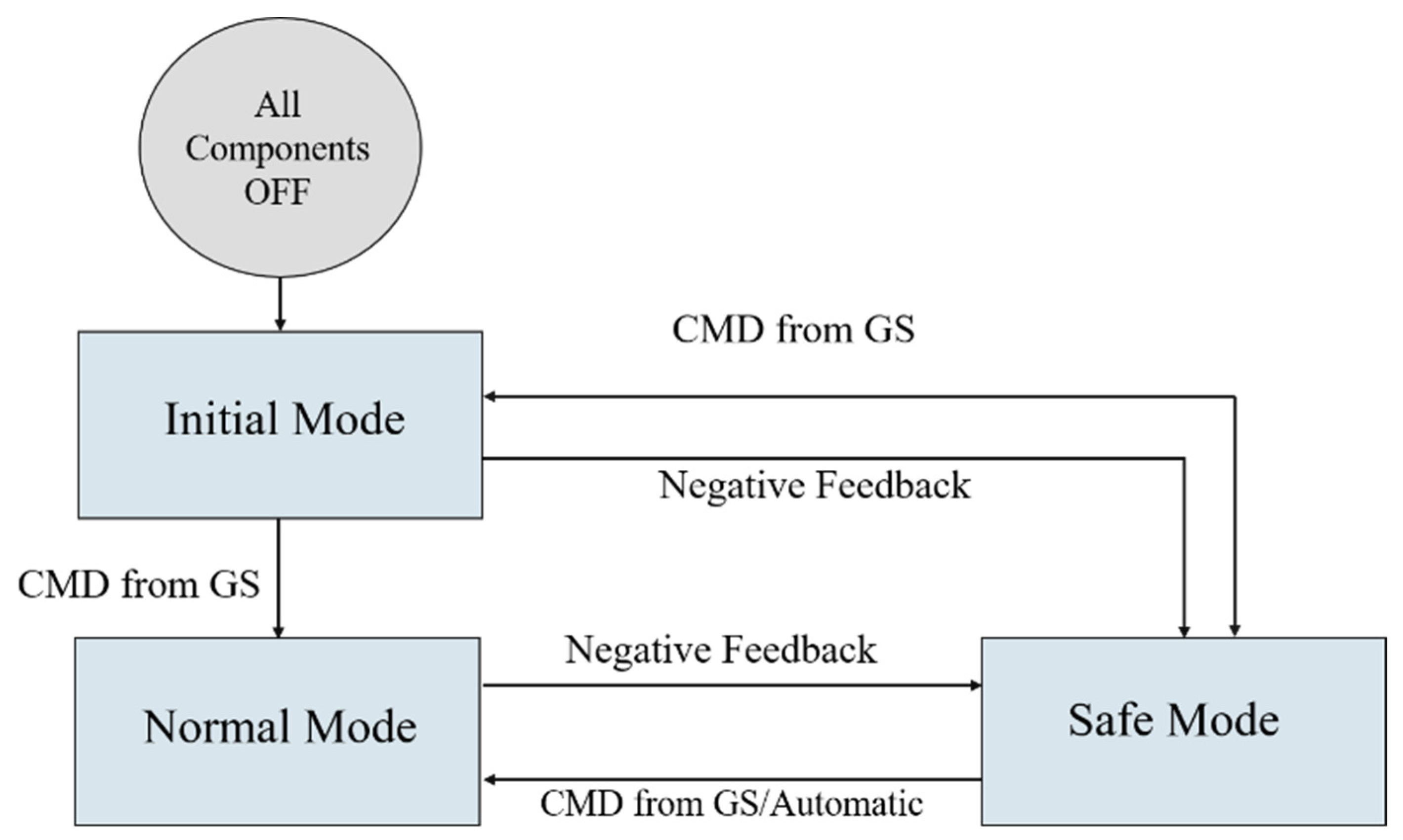
2.3. Mission Concept of Operations

This section presents a detailed concept of operation (ConOps) during the mission operation of Light-1. The satellite operates in three main modes, which are initial, normal, and safe mode. As illustrated in Figure 1, before the CubeSat ejection from the PPOD, all components will be switched off. After the ejection, Light-1, by default, it will enter initial mode, in which it will perform a health check of all the components. In case of any abnormal activity in any of the components during the initial mode, Light-1 will automatically switch to safe mode, otherwise, initial mode operations will be conducted sequentially. After executing initial mode successfully, normal mode will be activated through a command from the ground station. In normal mode, all regular operations such as payload data collection, attitude pointing, payload data transmission, and housekeeping data transmission will begin. If any negative feedback occurs during the normal operation, Light-1 will switch to safe mode automatically. If any abnormalities are visible in the received telemetry data, Light-1 will be switched to safe mode after receiving a command from the ground station. While in safe mode, depending on the present fault, a unique failure detection isolation recovery (FDIR) plan will be executed. The transition from safe mode to normal mode can be either through an automated process or a command from the ground station.

2.3.1. Initial Mode

After the first power up, Light-1 operation will begin from initial mode. It is essential as it has a safety period of 45 min after ejection without performing any operation to ensure that it is away from the deployer. This mode’s sole responsibility is to probe the system’s health and ensure all components coincide and are working correctly. Thus, the attitude determination and control subsystem (ADCS) will operate in case of a needed de-tumbling operation. After the initial 45 min safety period, if the Light-1′s electrical power subsystem (EPS) power is above the 50% threshold, the UHF antenna deployment process will commence. The antenna deployment is a critical process since the transmitted beacons will include all the information related to the CubeSat’s state. In order to mitigate the risk of an unsuccessful antenna deployment, the satellite requires the angular velocity rate to be within 20 deg / s . If the required rate is not achieved, the detumbling process will automatically start. After the antenna deployment is successful, Light-1 will begin the beacon transmission process with an interval of 30 s, and then continue with the solar panel deployment process. Once again, the solar panel deployment is conditional to a specific limit of angular velocity. After deploying the antenna and solar panels, Light-1 will enter the detumbling mode if the angular velocity is higher than 5 deg / s in each axis. After the detumbling process is completed, Light-1 will wait for a command from the ground station to switch into normal mode and begin its operations.

2.3.2. Normal Mode

In this state, the normal operation of the mission starts, and a beacon is transmitted periodically. While most of the subsystems will be powered ON continuously, certain will have conditions. During normal mode, different processes run simultaneously, this includes the beacon transmission, the ADCS, and the health check process. The latter is essential to keep monitoring the health of the CubeSat and acts accordingly in case of an abnormal telemetry reading. Negative feedback from the health check process can be due to low power, component’s high/low temperature, failure of task execution within a time limit, high angular velocity, and any other sensor reading that can present abnormalities. This negative feedback will lead to switching Light-1 from normal mode to safe mode. The payload operation requires data from the Sun-horizon, in which the detectors must point toward the Earth’s horizon to collect the specific data required. Hence, the ADCS subsystem will operate and will be responsible to always achieve this pointing requisite. When the CubeSat is within range of the ground station, the ADCS will change into target pointing toward the ground station as this has higher priority. Target pointing is required to achieve line-of-sight communication with the ground station to start downloading data using S band. Thus, the S band transceiver will be conditionally powered ON when payload data downlink is needed. Light-1 will receive commands and transmit housekeeping data during the ground station access time using a UHF transceiver.

2.3.3. Safe Mode

Safe mode is used to identify and correspond to any emergency that can occur during the CubeSat’s lifetime. This mode is triggered automatically by the on-board computer software as a result of negative feedback from any subsystem. It can also be initiated after receiving a command from the ground station, which enforces a special FDIR plan. When this mode is triggered, it requests to power OFF most of the components except the critical ones, such as the OBC, the EPS, and the UHF transceiver. During this state, the UHF transceiver will only be receiving and accepting commands and transmitting the beacon. If the battery power level drops below the desired limit of 50%, a full Sun-tracking mode is activated in which Light-1’s ADCS will entirely point the solar panels toward the Sun to maximize energy production. Moreover, in case of a high angular velocity rate, the de-tumbling process will be executed until it reaches the safety limit. If all the problems are resolved, Light-1 will switch back to normal mode automatically. Otherwise, Light-1 will wait for a command from the ground station to switch to normal mode. Ground station operators may resolve the problem manually through a command from the ground station.

2.4. Mission Analysis

Light-1 lifetime mission requirement is a six-month operation. Since the payload requires a low altitude as an area of interest for scientific purposes, Light-1 will be deployed from the International Space Station (ISS) at an altitude of 400 km and an inclination angle of 51.6°. Lifetime and access time analysis were conducted using the System Tool Kit (STK) to ensure Light-1 fulfils the mission requirements. The process is outlined below, along with the results:

2.4.1. Lifetime Analysis

The lifetime of a spacecraft is the main aspect that is focused on in the mission planning step. Many factors affect the lifetime of a CubeSat, such as solar flux, atmospheric drag, Earth gravity, orbit configuration, satellite mass, and drag area. The solar radiation pressure caused by solar flux is insignificant in the low Earth orbit (LEO) compared to the other factors. To ensure Light-1 meets the mission lifetime requirement of 6 months, all the parameters were evaluated as if in the worst case. In the unpredictable space environment, the attitude is the only controllable variable that affects the drag area directly. Thus, different drag areas were considered based on the CubeSat orientation, assuming vertical orientation with deployed solar panels (0.09 m 2 ), undeployed solar panels in vertical orientation (0.03 m 2 ), and a horizontal orientation with undeployed solar panels (0.01 m 2 ). For the worst-case drag area, 0.09 m 2 was used with the worst space environment condition parameters, such as the highest solar flux activity and high coefficient of drag. CubeSats usually have a drag coefficient between 2 and 2.2. In this simulation, 2.2 was used as the worst case. Implementing this simulation in STK with three different drag areas as mentioned yields a mission lifetime of 191 days, 1.3 years, and 2.2 years, separately. This is to emphasize that while an active drag area of 0.09 m 2 achieves the mission lifetime requirement, the required orientation of Light-1 is horizontal, hence an active drag area of 0.01 m 2 and a resultant lifetime of 2.2 years.

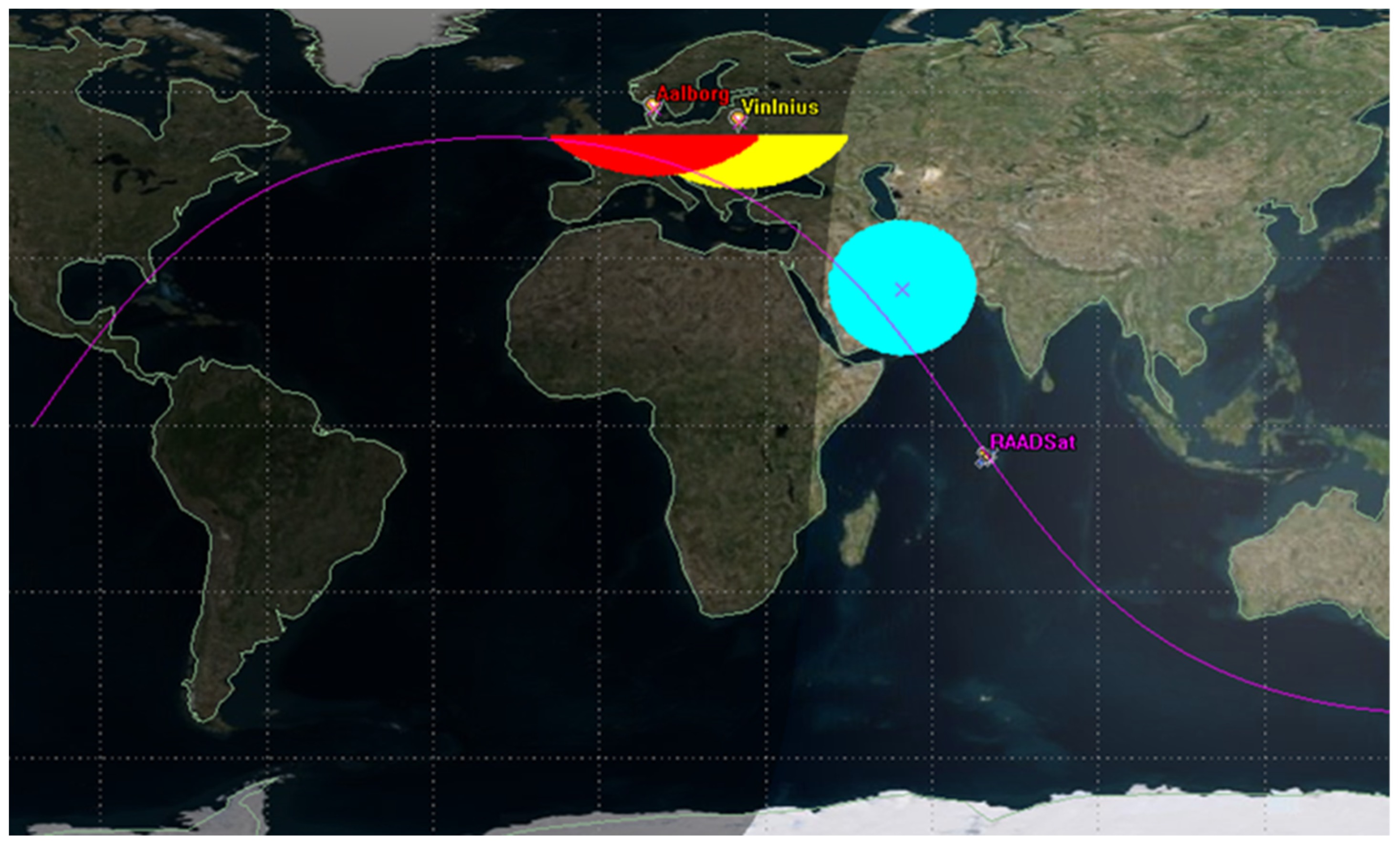
2.4.2. Access Time Analysis

As part of mission planning, access time is crucial for satellite missions. Many analyzers rely on the access time analysis, such as the data budget calculations, power budget calculations, and attitude determination, which is mandatory in planning the concept of operation of the mission. Light-1 can communicate with three ground stations: Abu Dhabi in United Arab Emirates, Vilnius in Lithuania, and Aalborg in Denmark. The three ground stations are used for S band downlinking, while UHF transmission uses the ground station in Abu Dhabi. Thus, access time simulations were conducted for three ground stations. The access time is calculated per day to validate that daily generated payload data can be downloaded in the worst and average case. The ground stations in Vilnius and Aalborg are situated close to each other. Therefore, due to the high speed of the CubeSat, an overlap in the access time between the two ground stations will occur, which can be seen in Figure 2. As a result, in case of an overlap, the access time of Vilnius ground station will be considered. The result shows that using the three ground stations, the average access time per day is 37.14 min / day , a minimum of 22.3 min / day , and a maximum of 64.73 min / day .

3. Platform Subsystem Design

This section gives an overview of all the bus subsystems, highlighting the hardware components and functions of each. Since the payload detectors will require a volume of approximately 2U, a 3U size was apt for the Light-1 mission, with the bus components occupying approximately 1.3   U of the CubeSat. A 3 U configuration is a stack of three 1 U CubeSats with dimensions of 100 × 100 × 340 mm . While the payload detectors are fully designed, developed, and tested by the students, the majority of the bus components of the satellite were purchased off-the-shelf from the vendor, NanoAvionics, each of which has flight heritage and hence is space qualified. A detailed assembly is included in Section 3.1. The Light-1 bus, similar to any other CubeSat bus, consists of mechanical, power, command and data handling, attitude determination, and control and communication subsystem—each of which have been described in thorough detail in Section 3.1, Section 3.2, Section 3.3, Section 3.4 and Section 3.5. The overall system-level block diagram of Light-1 is shown in Figure 3, while a detailed pin-level diagram has been included as Figure 4.

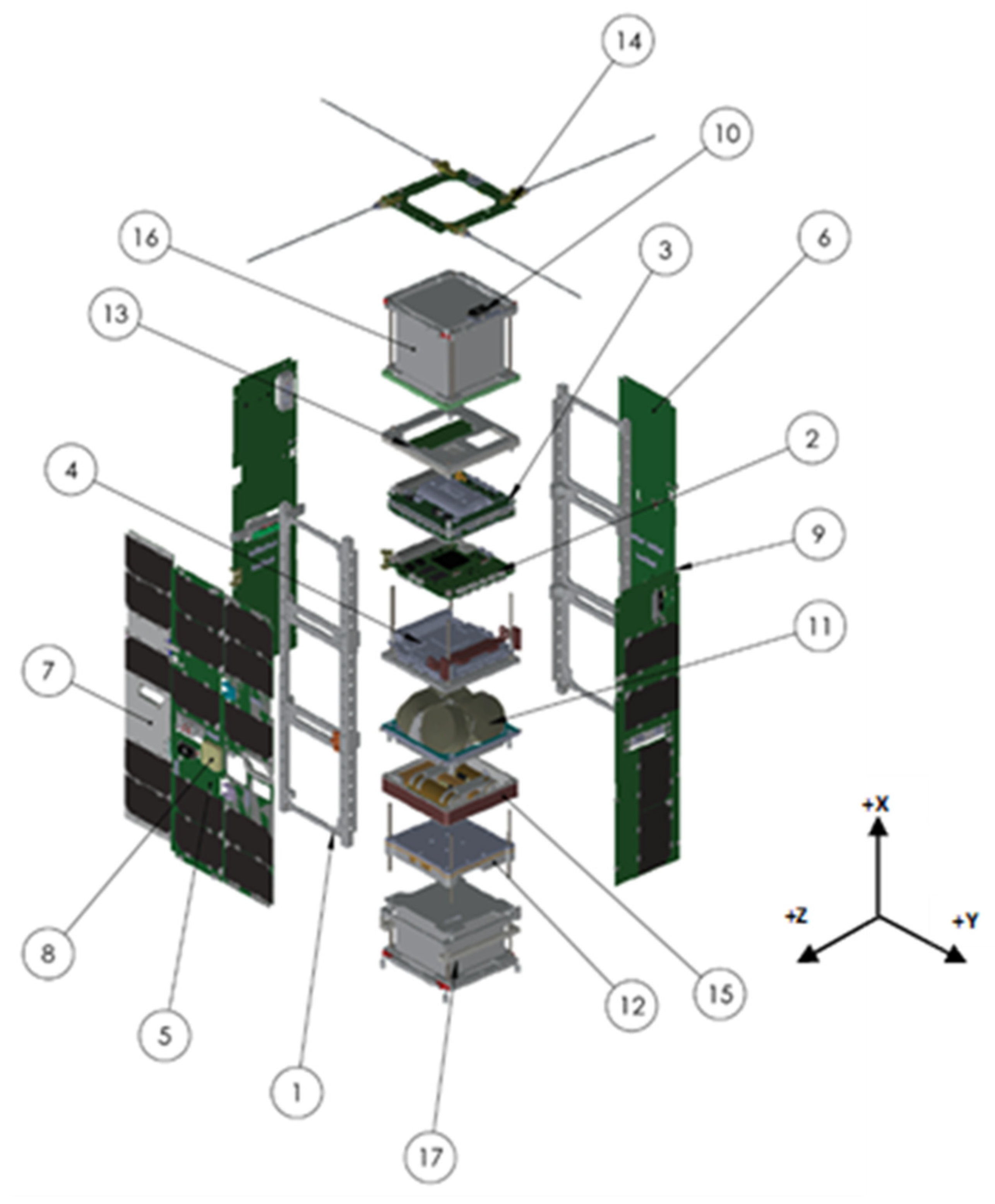
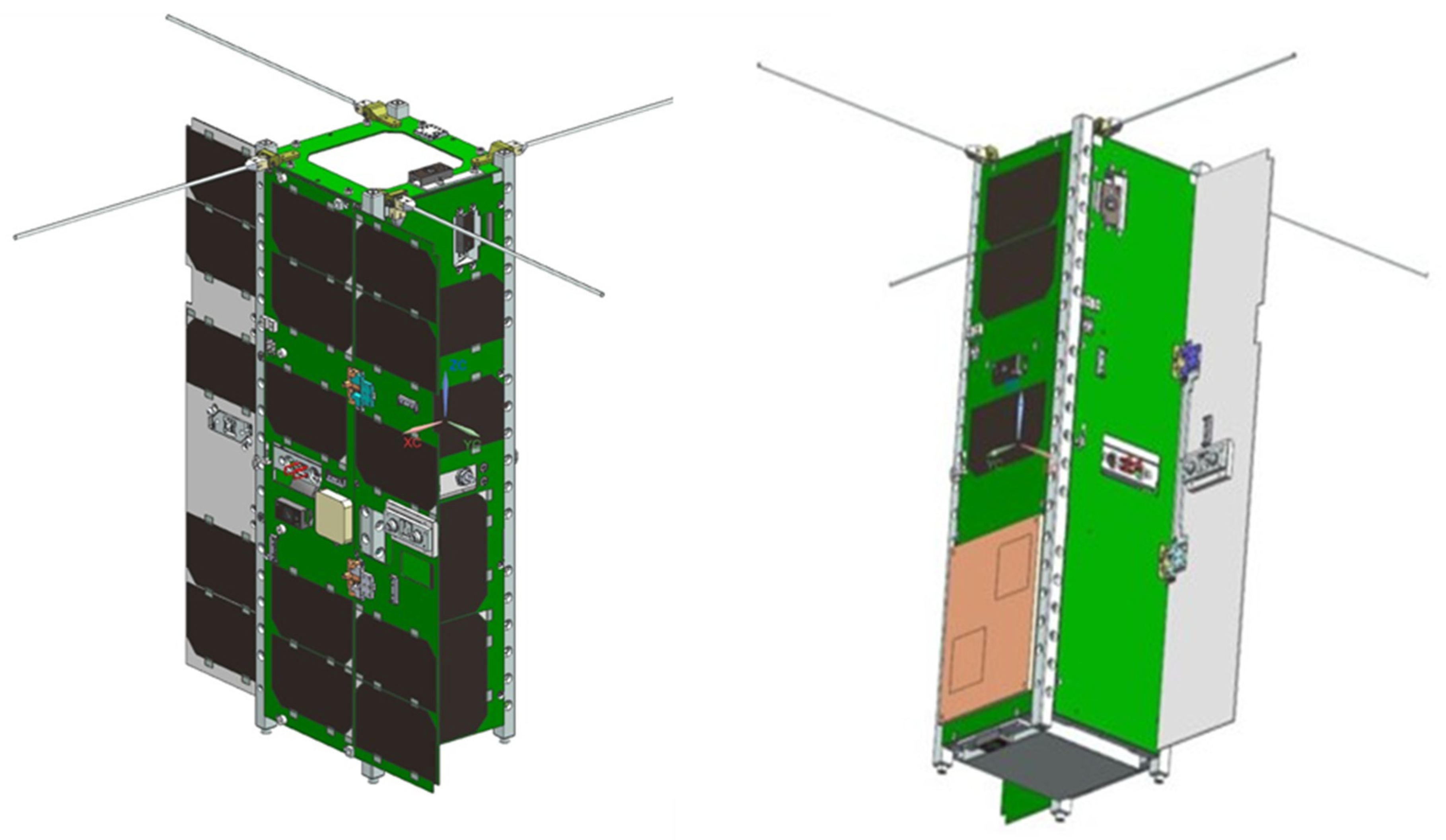
3.1. Mechanical Subsystem

An off-the-shelf 3U CubeSat frame composed of space-grade aluminum alloy was used for the structure of Light-1. The components of the Light-1 CubeSat can be seen in Figure 5 while the corresponding parts have been compiled in Table 1.
All the components in Light-1 are connected to the mechanical structure via steel rods, while both payloads rest on brackets to support their weight. There are two solar panels on the + X and − X faces and one solar panel on the + Y face, which are connected to the structure with screws. Two deployable solar panels are connected with hinges. The UHF antenna and the deployable solar panels are connected to the EPS subsystem by a burn wire. Upon deployment, power will be delivered to the wire. Consequently, the wire will heat up and eventually cut, releasing the stowed antennas and solar panels. Each antenna is mounted on a spring-loaded hinge with 7075 grade aluminum housing. A 3 cm burn wire is then used to tie up the antenna rods. Light-1 power connection has two levels, 3.5 V and 5 V in which each component requires a different level. The OBC, UHF antenna, payload controller, GPS receiver, fine Sun sensors and both payloads require 3.5 V , while the magnetorquers and reaction wheels require 5 V . The S -band transceiver has a Vbat power connection because it requires 8.3 V .

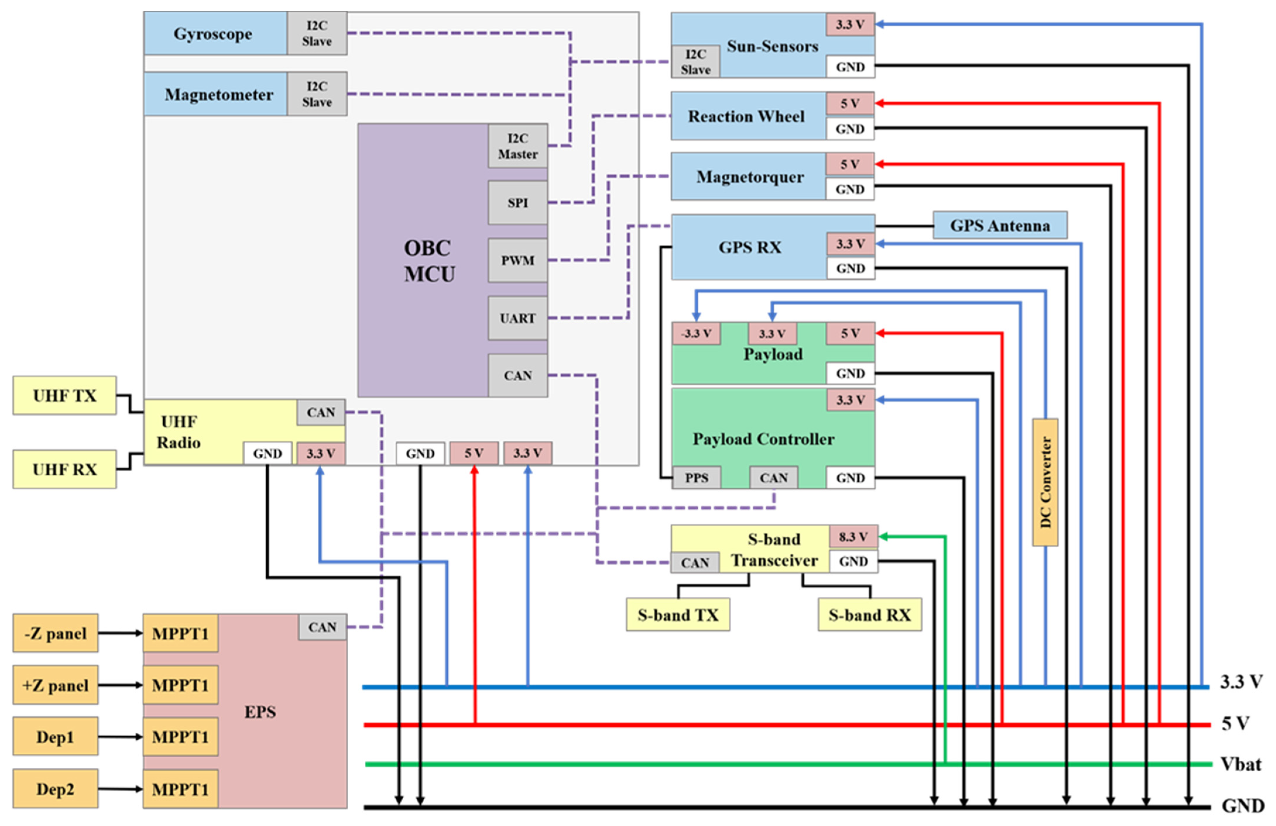
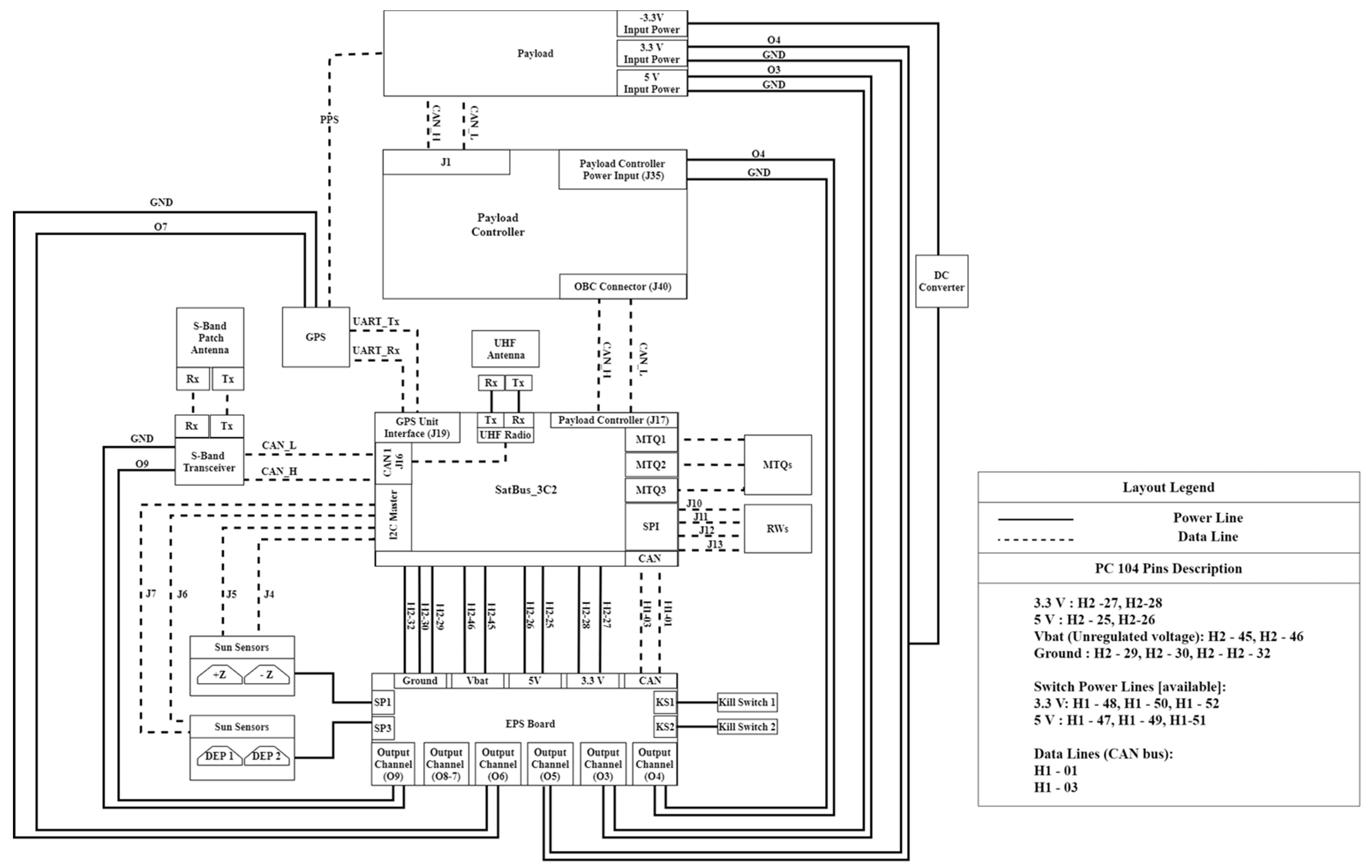
3.2. Power Subsystem

The electrical power subsystem (EPS) of the CubeSat generates power from high-efficiency solar cells that harvest solar energy and convert it into electricity. The excess energy is stored in a rechargeable battery, which is utilized when there is no access to solar power. In most cases, the CubeSats uses the stored energy during eclipses to operate. In addition, the EPS manages the electrical energy by utilizing converters to distribute the power to all subsystems, including the payload. To ensure that the CubeSat operates throughout its mission time, the EPS is designed precisely to meet the power requirements of each component. The Light-1 EPS subsystem consists of three main components: the solar cells, the EPS board, and the battery pack.
The solar panels contain a triple junction of GaInP/GaInAs/Ge. The solar cells in the solar panels have a maximum power of 1.05 W with an efficiency of 29.5%. The EPS board is responsible for managing and distributing the electrical power. It consists of several electronic circuits that regulate and control voltages to meet the voltage demand of all the subsystems. One of the main features of the EPS board is that it can track the maximum power point (MPPT). The Light-1 EPS board also contains protective features such as overcurrent and overvoltage protection for various components of the board. The EPS includes a distribution unit that employs converters to step down/up the voltage according to the subsystems/load operating voltages. The lithium-ion (Li-ion) battery is used for storing excess power that is used when solar power is unavailable. Light-1 has four Li-ion battery cells with each cell voltage of 3.6 V and 3200 mAh capacity. Light-1 is a 3 U CubeSat with two deployable solar panels. The deployable solar panels help in increasing the power generated during sunlight. Light-1 has 22 solar cells distributed across five solar panels of which two are deployable. Figure 6 shows the distribution of the solar cells in each panel.

3.3. Command and Data Handling Subsystem

The on-board computer (OBC) acts as the brain of the satellite, which allows controlling of the operation and data handling of all the subsystems by managing the different subsystem modules. It also synchronizes the CubeSat clock with the ground station. The OBC collects system data such as temperature, voltage, current, and other sensor readings. While subsystem critical health data is transmitted in beacon packets, other data is stored as housekeeping data, which is duly sent to the ground station through the communication subsystem. The OBC processor executes all commands received from the ground station. Scheduling between different tasks is managed through the OBC software, which operates by a real-time operating system. Moreover, all modes of operation are implemented in the OBC software. The command list used by the ground station operator relies on the subsystem’s command requirements. Thus, each mission has a different command list in which each command has a unique code structure defined by the software developer.
In this mission, the OBC has an integrated ADCS sensor and is compatible with ADCS actuators. As the Light-1, OBC implements the ADCS algorithms on-board, the OBC takes the ADCS sensor readings, processes them, and operates the actuators accordingly. Although the Light-1 OBC is not responsible for storing payload data on-board, a prioritization plan is implemented onboard for payload data transmission. The OBC software also accounts for different levels of authentication. It provides different privileges based on the user type level, i.e., user, superuser and manufacturer. A user can perform normal operations such as downloading satellite data. A superuser can configure certain parameters in addition to normal operations. However, certain parameters are restricted to the manufacturer, such as the parameters related to the control and determination algorithms.
The NanoAvionics SatBus3C2 was chosen according to the detailed system requirements satisfactory evaluation. This OBC board has an integrated UHF module and ADCS sensors, magnetometers, and gyroscopes with a low power consumption of 0.287 W . Its processing unit implements the flight controller software as well as the ADCS algorithm onboard. It is an ARM 32- bit with 400 MHz processing speed. In addition, it supports different data buses such as I2C, CAN, UART, and SPI. The CAN bus is mandatory for payload interfacing with the OBC, due to its higher transmission speed compared to the I2C bus. Thus, the CAN bus is used to connect the OBC with the communication system and the payload. Moreover, it supports an SD card for storage, allowing 64 GB on board for storing housekeeping data.

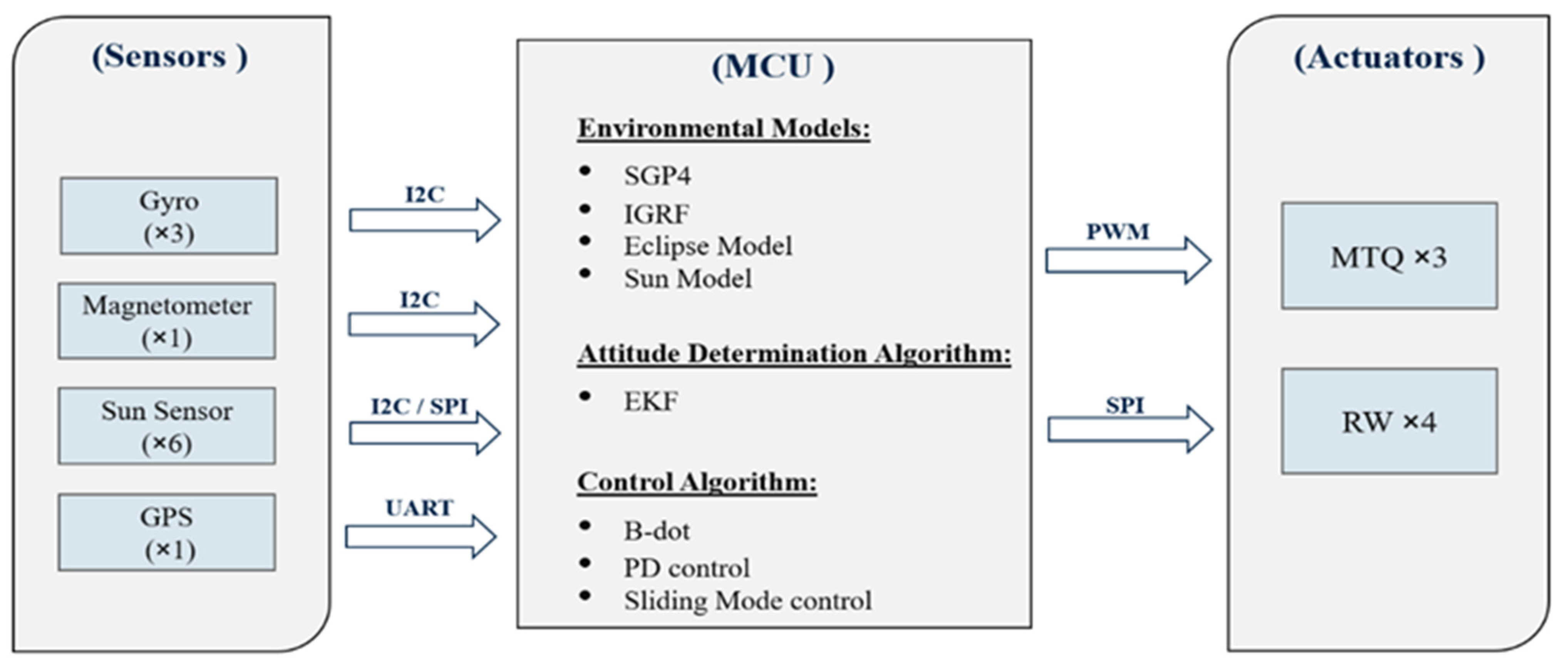
3.4. Attitude Determination and Control Subsystem

The attitude determination and control subsystem (ADCS) stabilizes the satellite and holds it in place, thus fulfilling the mission and payload requirements. This system consists of two parts: the determination and the control part. The former acknowledges the position and the velocity vectors of the satellite and points the orientation of the satellite faces, while the latter directs the satellite to a certain location by maintaining pointing or reducing spin rate. Sensors collect and measure different variables and transfer them to the microcontroller unit (MCU). In the MCU, libraries of environmental models, attitude determination algorithms, and control algorithms prepared by NanoAvionics will fuse the readings to attain position and velocity vectors. The control algorithms then send a command for a certain pointing requirement to the components, which will spin the satellite to the target point until it achieves the pointing accuracy. A breakdown of the Light-1 ADCS can be seen in Figure 7.
The Light-1 ADCS determination system consists of three three-axis gyro sensors, six fine Sun sensors, three three-axis magnetometers, and a GPS. The gyro sensors are provided by NanoAvionics and embedded on the OBC board. These gyro sensors measure the angular velocity for attitude determination during an eclipse. The accuracy of the gyros is increased by averaging three gyros readings. The cross-axis sensitivity of these gyros is 1 deg / s . The fine Sun sensors are located on each side of the satellite to measure the Sun vector for attitude determination and partial Sun tracking mode. The magnetometer, embedded on the OBC board, measures the magnetic field of Earth for attitude determination. The GPS has two main components: the GPS receiver and the GPS patch antenna, which consists of the patch antenna and the low noise amplifier. The GPS receiver placed on the OBC board synchronizes payload data and time to predict when an event occurs. The timing accuracy of this receiver is 10 ns . The GPS patch antenna is located on the + Z axis face of the satellite.
The Light-1 ADCS control system consists of four reaction wheels and three magnetorquers. The reaction wheels stabilize the CubeSat and perform fine attitude pointing, while the magnetorquers are responsible for high spinning control situations and the desaturation of the reaction wheels. The magnetorquers are the only controllers used in the detumbling mode after ejection.

3.5. Communication Subsystem

The communication subsystem’s role is to transmit and receive telemetry, mainly payload and housekeeping data between the ground station and the satellite. For the uplink telecommands and downlink house-keeping data, the subsystem utilizes ultra high frequency (UHF) for communication. The UHF Digital Radio has a sensitivity of −118 dBm and uses a frequency between 430–440 MHz . It operates at 2400 bps with GFSK2 modulation technique. The UHF transceiver is coupled with a UHF dipole antenna that has a gain of 2 dBi . Both UHF transceiver and antenna have an operating temperature between −40 and +85 °C. Moreover, for downlink of payload data, the subsystem utilizes S -band for communication. The S -band transceiver has a sensitivity of −110 dBm and uses a frequency of 2035.5 MHz for uplink and 2208.2 MHz for downlink. It has a transmission rate of 1.28 Mb / s for uplink and 5.12 Mb / s for downlink using GMSK modulation technique. Additionally, the S -band is coupled with a directional antenna, and a S -band patch antenna which has a gain of 6 dBi . The communication subsystem also acts as a messenger between the OBC and the ground station. In the case of uplink telemetry, the subsystem receives the data from the ground station and passes it to the OBC, which translates it to commands. While in the case of the downlink, the subsystem receives the information, housekeeping data, or payload data from the OBC and sends it to the ground station.

4. Design Analysis

4.1. Ballistic Number

JAXA requires the satellite to have a maximum ballistic number of 120   kg / m 2 [3]. As seen in the calculations below, a maximum mass of 5.225 kg , with a safety margin, conforms to JAXA’s requirements. A detailed breakdown in Section 4.2 shows the Light-1 assembly weighs 5.040 kg and hence satisfies the requirements.
B N = M / ( C d × A ) = 118.6   k g / m 2 ,
was used to calculate the ballistic number where
M: the mass of a satellite [kg];
C d : coefficient of drag (=2) [*];
A: minimum average frontal area [ m 2 ].
A value of 2 was used for the coefficient of drag as it was specified by the satellite launchers. An average of the horizontal (0.1 × 0.1 = 0.01 m 2 ) and vertical (0.1 × 0.3405 = 0.03405 m 2 ) area was used to acquire the minimum average frontal area (0.022 m 2 ).

4.2. Mass Budget

The total mass of the Light-1 assembly is 5.040 kg , with an estimated 5% margin for wiring and harnessing, a breakdown of which can be seen in Table 2.

4.3. Power Analysis

The design of the solar panel structure combines deployable solar panels since the power consumption of Light-1 is considered relatively high for a 3U CubeSat. Yet, the deployable solar panels do not provide sufficient power for the mission. Therefore, to solve the power insufficiency, a new mode of operation, the Sun horizon pointing mode, is implemented. In this mode, the CubeSat will be tilted off Nadir with an angle that varies depending on the Sun vector. This mode increases the power generation of the solar panels since the CubeSat changes its orientation to maximize the power generation. Figure 8 demonstrates the Sun horizon pointing mode. The blue line represents the payloads on the + Z and Z axis, while the yellow cone represents the Light-1 main solar cells (deployable) on the + X face. In this mode, the payload is looking at the horizon continuously while performing yaw and roll attitude maneuvers to point the main solar panels ( + X ) toward the Sun.
The power generation of Light-1 was simulated using the Systems Tool Kit (STK) by mimicking the attitude of Light-1 in the Sun horizon pointing. The objective of the power generation simulation in STK was to calculate the expected power generation when Light-1 is in its orbit, with its intended pointing mode and the capacity of its solar arrays. To simulate the power generation for the sun horizon pointing mode, which is a non-typical pointing mode, the attitude of Light-1 was mimicked. The attitude type selected in STK was ‘aligned and constrained’, which gives the freedom of aligning an axis of the satellite with a specific object and constraining a second axis with another object. In Light-1′s sun horizon pointing mode, the Z axis was constrained by the Sun and the + Y axis was aligned with the Nadir axis. In addition, the power generation of Light-1 was simulated for Nadir and full Sun tracking pointing modes. Since these two pointing modes are standard, these were present as direct options in STK. The results of the power generation simulated are illustrated in Table 3. The results show that the Sun horizon pointing mode generates more power compared to the Nadir pointing mode. Hence, the Sun horizon pointing mode is capable of providing sufficient power for the mission as illustrated in the power budget.
The payload will operate most of the time during the tropical regions with a latitude of −23° to +23°. By using simulations to find the duration according to the orbit duration, the results show it is approximately 50% of the orbit. All three ground stations will be utilized to communicate with Light-1 and attain the payload and housekeeping data. S b a n d transceiver is mainly used to download payload data. The UHF transceiver will download the housekeeping data and transmit beacons. Beacon transmission will require operating the transmitter around 6.2 min. The duty cycles of the S b a n d transceiver and the UHF transceiver are computed based on the maximum access times to the ground stations. Therefore, the maximum access time to Abu Dhabi ground station is 6.5 and 5.1 min for Vilnius and Aalborg ground stations, respectively. The access time of Vilnius and Alborg ground station is less of that compared to the ground station in Abu Dhabi since there is an overlap of the access time as they are close to each other. The power budget of Light-1 is calculated by considering the power generation and consumption during different modes of operation. Since the power generation was calculated from STK, the next step was to compute the amount of power consumed during the different modes of operation. In each mode of operation, different components will operate for a specific time in the orbit, i.e., certain components will be switched off, others will operate for a certain time during the orbit, while others will be operating throughout the orbit. Thus, the duty cycle of each component was retrieved, along with the power consumption. Furthermore, since the components might have different power consumption values, the highest power consumption value was selected to account for the worst case when calculating the power budget. Additionally, before computing the energy consumption, the components power consumption was increased by 10% to account for the EPS losses that occur due to the converter’s inefficiencies [4]. Table 4 represents the power budget of Light-1 during different modes of operations with an assumption that the payload will operate throughout the orbit, to account for the worst-case scenario. The power consumption during different modes of operation is less than the energy generated by the solar panels. Thus, the EPS is capable of sufficiently providing power for the mission.

4.4. Data Analysis

The housekeeping (HK) data generated by Light-1 is essential for monitoring the health and status of the CubeSat. The data is collected and stored in the on-board memory within a three-level data file structure. The first level includes a folder for each subsystem: OBC, EPS, ADCS and COM, the second level is a subfolder created for the predefined variables, while the final level contains two types of files, i.e., actual data file and indexing file.

4.4.1. Actual Data File

The actual data file includes the variable values that are captured according to the predefined interval. Three conditions to create a new file exist: a change in the collection interval, OBC reset, or the file size reaching the threshold of 2 kB .

4.4.2. Indexing File

The file includes the timestamp where the actual data file has been created, along with the collection interval. Previous missions MySat-1 and E-st@r-II followed a similar data packet structure, where data retrieved was packet based; in other words, telemetry data was collected at certain intervals and stored in one packet. For instance, the packet size was 113 and 35 bytes long for E-st@r-II and MySat-1, respectively [5]. Another data structure was implemented by AAUSats, where the packet format is in two packet length, 25 or 86 bytes long and distinguished by a one byte hexadecimal indicating a long or short packet [6].
The advantage of the data structure design is to overcome difficulties related to researching the data needed and mapping them to the actual collection time. The telemetry data is either transmitted as beacon or as requested by the ground station. The beacons include the CubeSat’s call sign, a counter for the OBC reset, the OBC uptime, OBC flags, and one general housekeeping packet, having a total of 193 bytes .
The data analysis considered the communication with a ground station located in Abu Dhabi, with minimum and average access time to simulate the minimum and average data budget to ensure the total generated data of 1.04 MB / day is received by the ground station. Table 5 shows a summary of the telemetry calculations with different UHF downlink rates. It is noticeable that the total generated data cannot be transmitted fully in these two cases. However, the data structure mentioned earlier allows data transmission based on priority and makes it convenient to request certain data from any interval.

4.5. Telemetry Analysis

Communication between the satellite and ground station may be affected by several factors such as signal propagation, space radiation, data rates and modulation techniques. Additionally, many signals are attenuated by amplifiers and antennas that work on increasing gain and reducing noise level. However, many signals and data are still lost during propagation. The link budget analysis accounts for all the gains and losses. The gains and losses are accounted for starting from the transmitter going through the medium (free space, fiber, or cable) until reaching the receiver using the equation below:
P R X = P T X + G T X + G R X L T X L F S L F M L R X ,
where
  • P R X = received power ( dBm );
  • P T X = transmitter output power ( dBm );
  • G T X = transmitter antenna gain ( dBi );
  • G R X = receiver antenna gain ( dBi );
  • L T X = transmitter feeder and connector losses ( dB );
  • L F S = free space loss or path loss ( dB );
  • L F M = many sided signal propagation losses ( dB );
  • L R X = receiver feeder connector losses ( dB ).
Light-1 utilizes UHF frequency to uplink commands to the satellite and downlink housekeeping data from the satellite. The UHF link budget for Light-1 is summarized in Table 6. In the table, it can be seen that the uplink and downlink margin are averaged to approximately 20, which is sufficient to create a clear linkage between the satellite and the ground station. The calculation of the UHF link budget has followed the Eb/N0 margin method. The method utilizes the operational parameters information, the satellite’s communication system information, and the ground station information to measure the strength of the communication.
As CubeSats are evolving with new missions that require higher data rates, S band frequency is being used to download data. Light-1 is one such CubeSat. The directivity of S band patch antenna requires the calculations to be with respect to different elevation angles, and consequently, different path distances as seen in Table 7. The table shows the variation detected in the link budget margin with changes in the elevation angle of the satellite. The downlink margin is found sufficient at elevation angles higher than 10°, which is satisfactory to establish clear communication between the ground station and the satellite. Similar to the calculation of the UHF link budget, the S band link budget has followed the Eb/N0 margin method.

4.6. Attitude Determination and Control Analysis
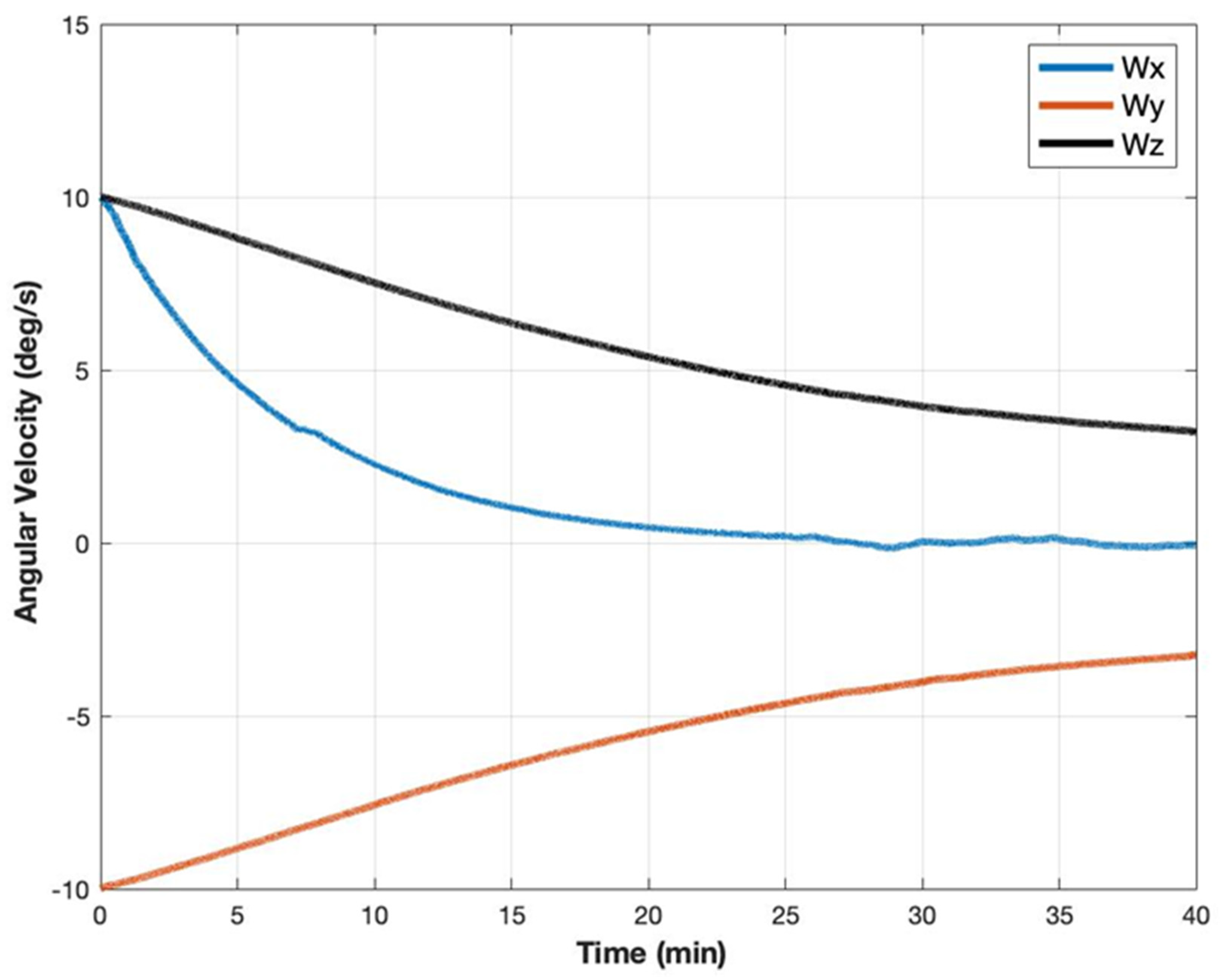
Detumbling and pointing analysis simulations were performed using MATLAB. The results of the detumbling and pointing analysis simulation performed using MATLAB have been presented in this section.

4.6.1. Detumbling

This mode is used whenever the norm of the angular velocity is higher than 5 deg / s . The common control law for this mode is the B-dot algorithm. The main idea is to use the rate of change of magnetometer readings of the Earth’s magnetic field as a feedback to the controller to produce the required torque from the magnetorquers and to counter the undesired angular rates. Simulations for the algorithm were conducted to track the time required for bringing up the norm of the angular velocity from a certain undesired value to the desired 5 deg / s using the magnetorquers only. For the purpose of simulation, the Earth’s magnetic field values were provided to the system from the International Geomagnetic Reference Field (IGRF) [7]. The IGRF is a well-known mathematical model that is provided in the north-east down (NED) reference of frame. Therefore, rotation matrices are required to convert from NED to the Earth central inertial (ECI). Table 8 and Figure 9 summarize one of the simulated cases, i.e., from 17.32 deg / s (10 deg / s on each axis) to 5 deg / s .
The result of the analysis showed that the time taken to derive the satellite’s norm angular velocity from 17.32 to 5 deg / s is 40 min which is less than one orbit of 90 min .

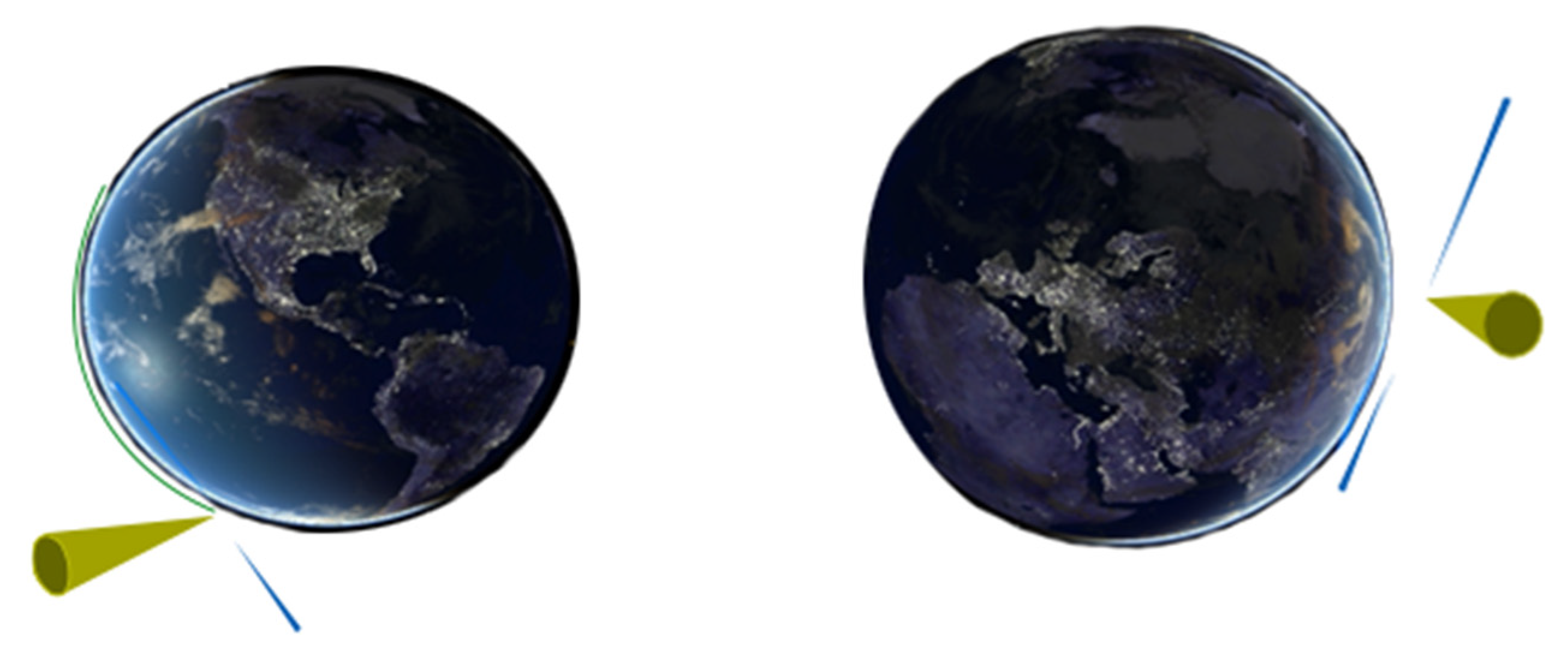
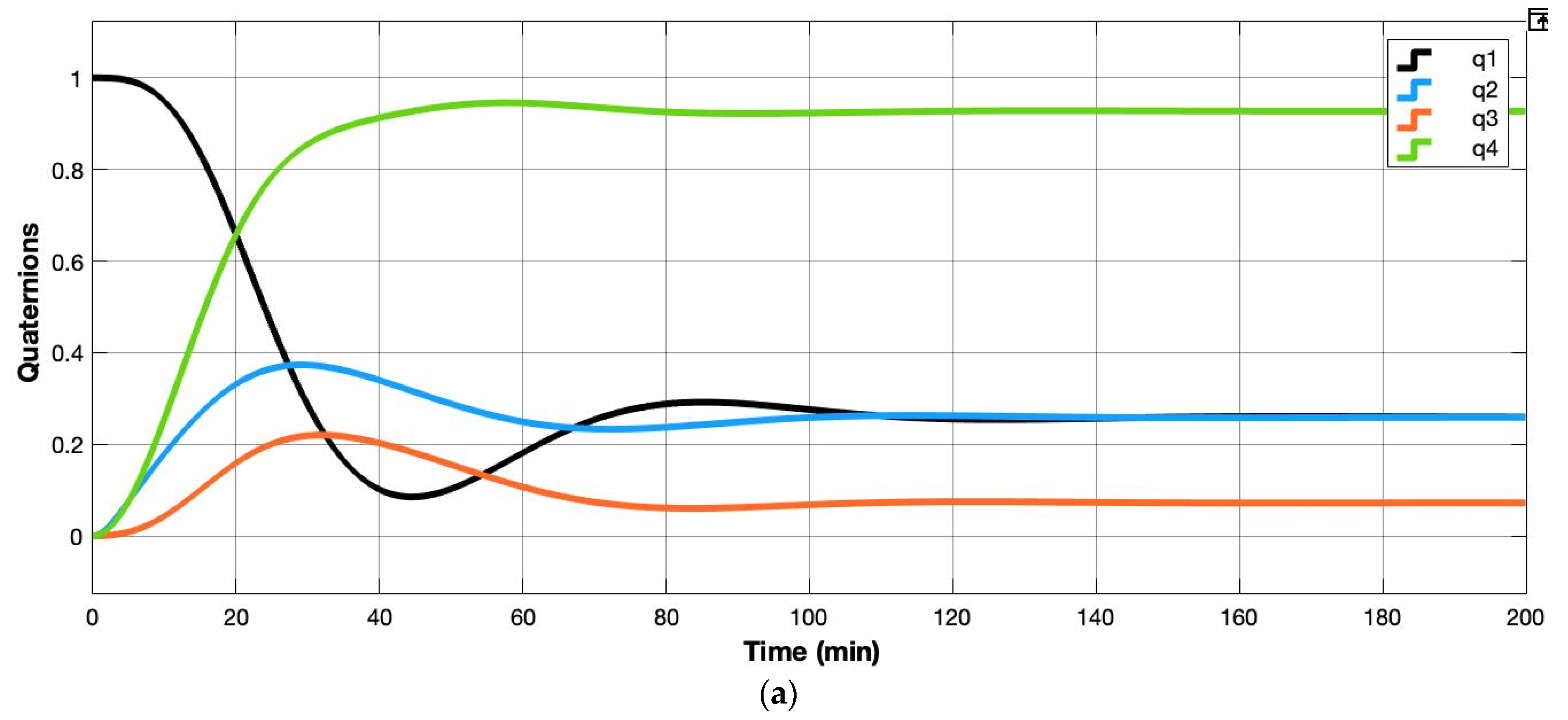
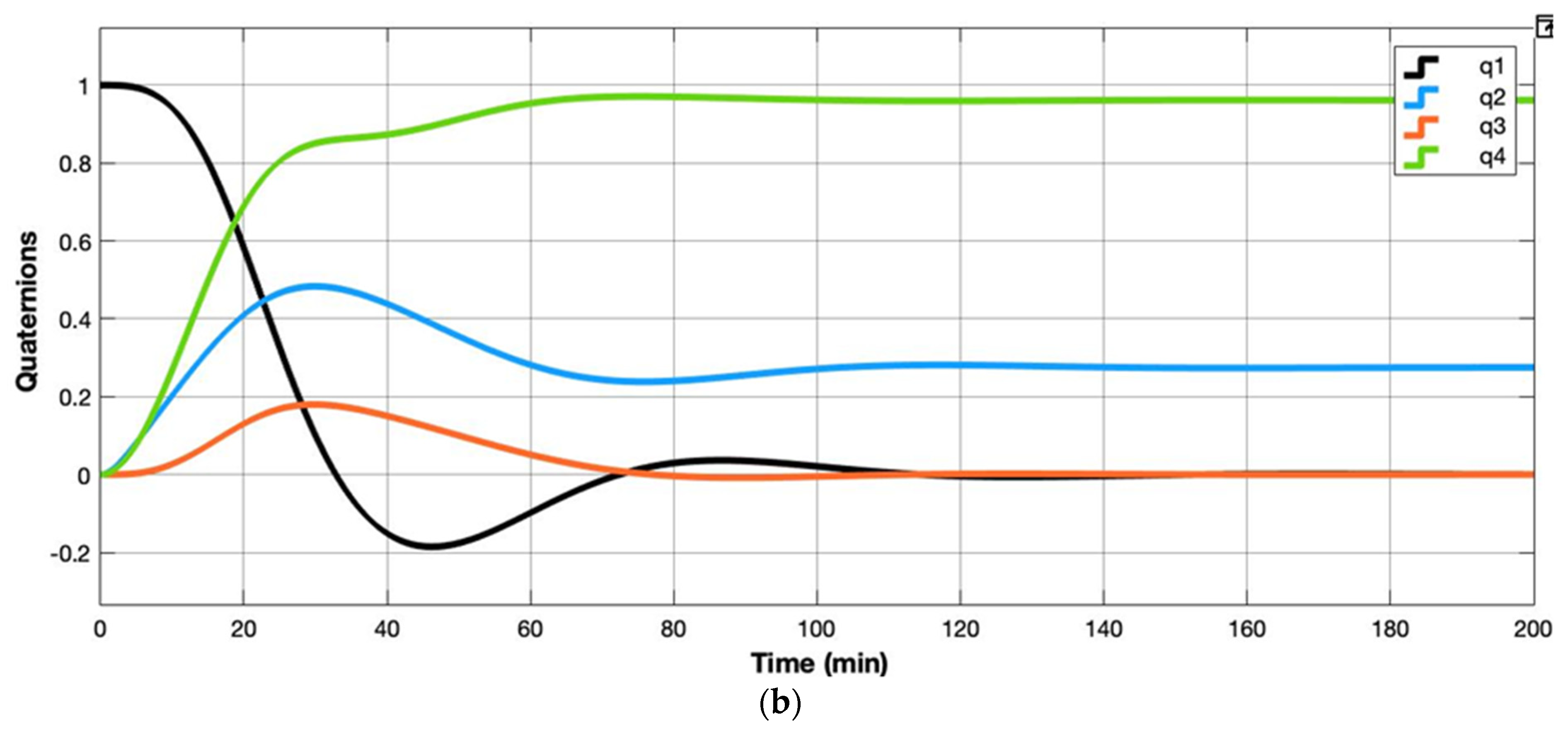
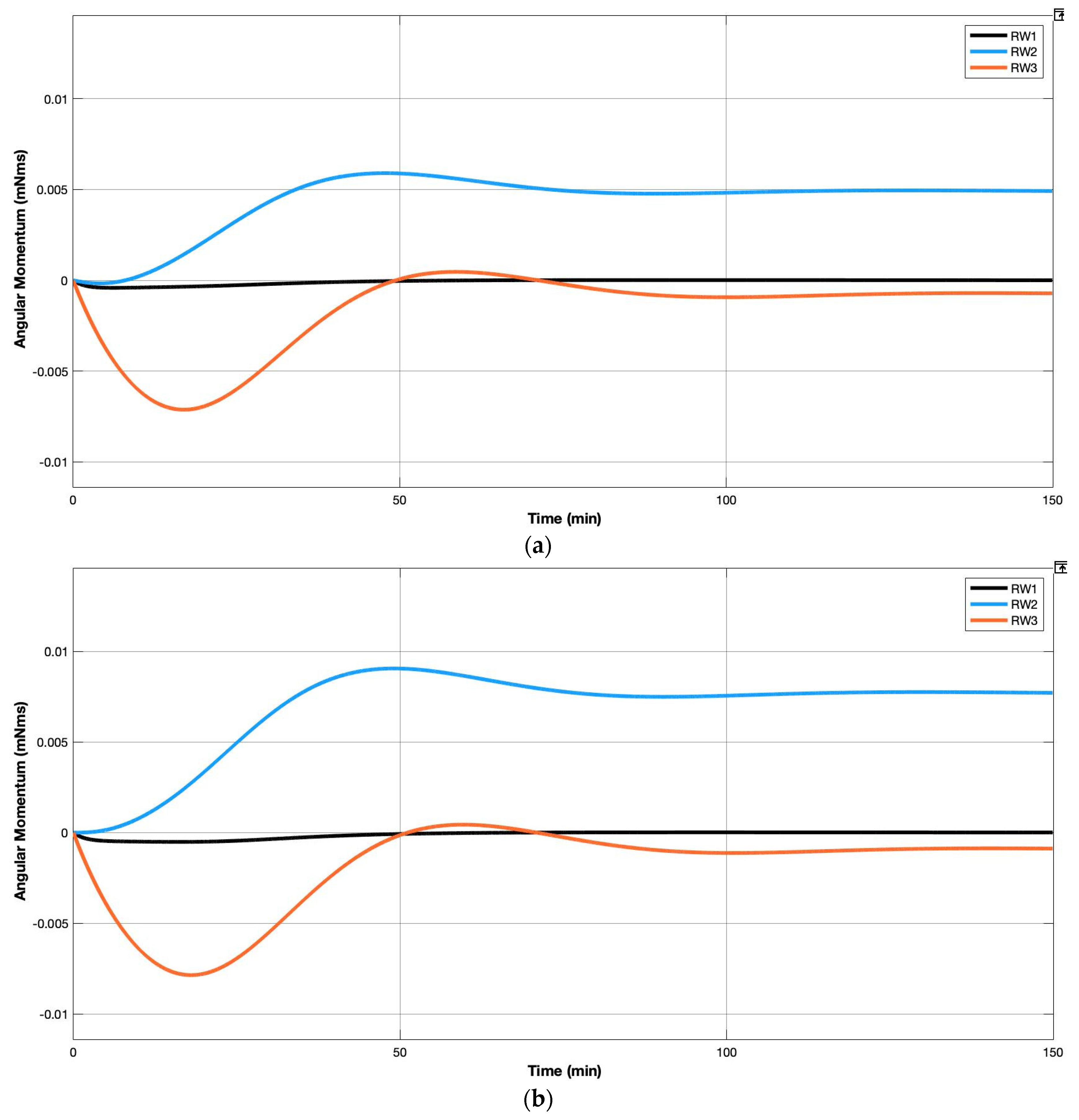
4.6.2. Attitude Pointing Analysis

A proportional and derivative (PD) controller was simulated to control Light-1 in orbit and to estimate the time Light-1 takes to change its attitude for pointing in Vilnius and Aalborg. The worst desired attitudes for target pointing in Vilnius and Aalborg were found by running a STK scenario, where the Euler angles were found for the life of 6 months. Only three reaction wheels are simulated in the Simulink block. The magnetorquer was not included in the simulations to ensure that the reaction wheels are able to maneuver and do not saturate. The environmental disturbances were assumed to be constant and represent the highest possible environmental disturbances. Table 9 shows the input values used to run the simulation, while Figure 10 and Figure 11 show the quaternion response and angular momentum response for the reaction wheels respectively for Aalborg and Vilnius.

4.7. Finite Element Analysis

For a CubeSat to function properly, it is expected to withstand the harsh conditions during launch in addition to the extreme thermal cycles while in orbit. During launch to space, the CubeSat will be exposed to accelerations several times larger than the gravitational acceleration in addition to extreme dynamic loads. The dynamic loads include low and high frequency along with random vibrations. The failure of CubeSat caused by vibrations during launch can result in damage of the CubeSat and the launch vehicle.
In this section, the focus is on the Light-1 assembly’s response to the quasi-static and vibrational loads during launch. It is deemed necessary for a successful CubeSat mission that the structure sustains these loads without failure. Therefore, it is necessary to predict the response of the launch vehicle loads to avoid these possible failures. The commercially available finite element software ABAQUS was used to conduct the structural analyses. An analysis procedure similar to [8] was followed.

4.7.1. 3D Model and Mesh

All analyses were conducted on the entire assembly, shown in Figure 12, which included the frame, components, and payload. All switches, springs, screw, bolts, Sun sensors, deployable, and suspensors were removed from the structure to simplify the 3D model. Instead, a tie interaction between surfaces was added to replicate the nut and screw functions. A simplified model of each subsystem was created to eliminate meshing errors.
The material used for the structure was Al 7075-T651, while stainless steel was used for the rods and spacers between boards. The material properties can be seen in Table 10. For the remaining components, the properties of the materials were characterized by their densities. The mass was obtained from the component datasheets, and the volume was obtained using CAD software. The Young’s modulus and Poisson’s ratio values assigned were that of FR4 material since it is the dominant material and also the lowest, thus representing the worst-case scenario for stiffness.
A hexagonal element mesh was assigned to all rods and spacers, while a quadratic tetrahedral element (C3D10) was assigned to all other components. Depending on the complexity of the part, the mesh size was chosen, which in ABAQUS, is characterized by the size of the seeds.

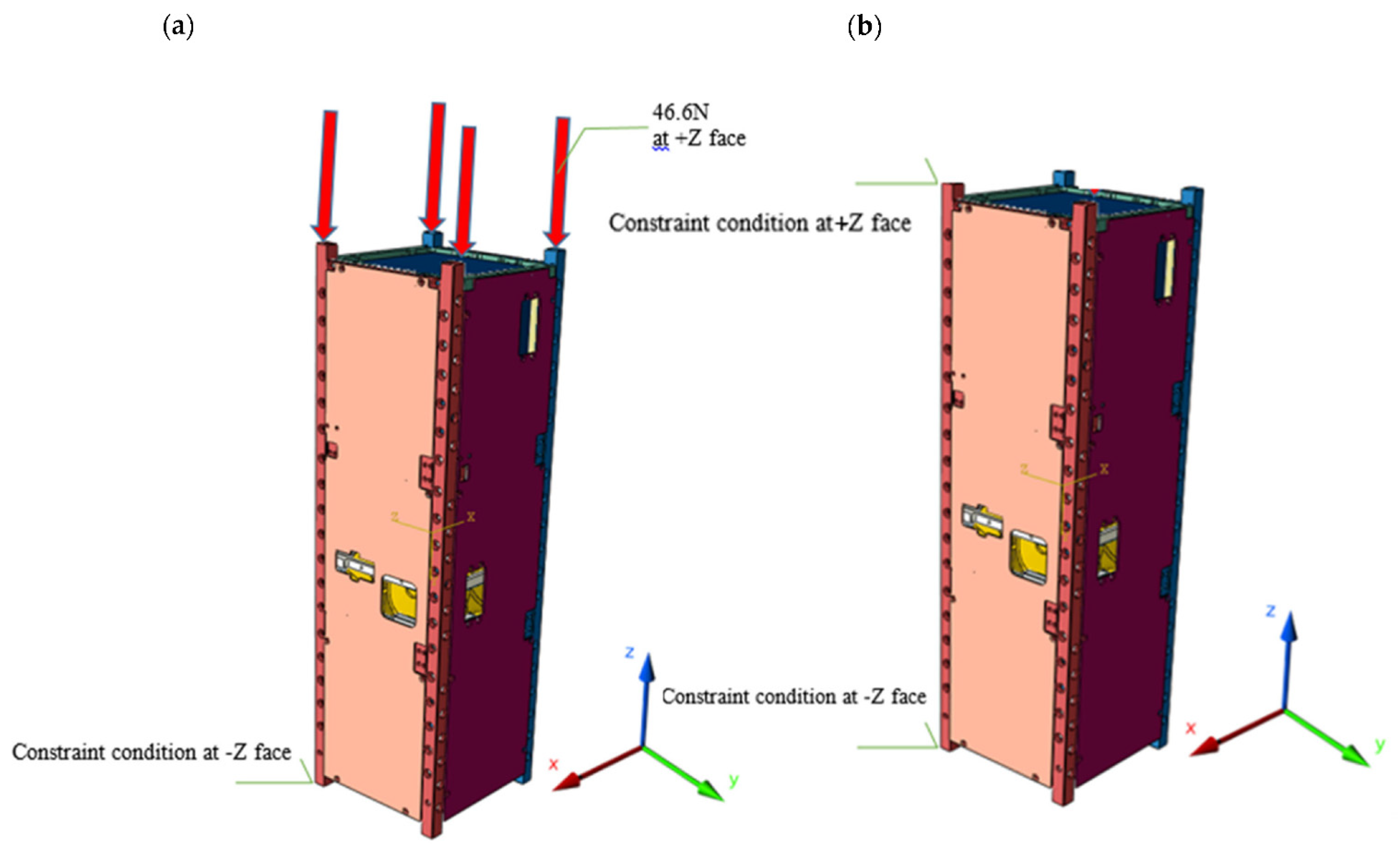
4.7.2. Boundary Conditions

The boundary conditions assigned to the model are based on the interaction between the CubeSat and the Satellite Install Case of the J-SSOD inside the launch vehicle. The CubeSat will be mounted in the J-SSOD. The boundary conditions were applied on the model as specified by the JEM Payload Accommodation Handbook, which is constraining the CubeSat in all directions at − Z face of the rails and exposing the CubeSat to a compression force of 46.6 N at each face of the rails in the + Z direction [3]. This compression force replicates that from the springs and the back plate on the structure. Figure 13 illustrates the boundary conditions applied.

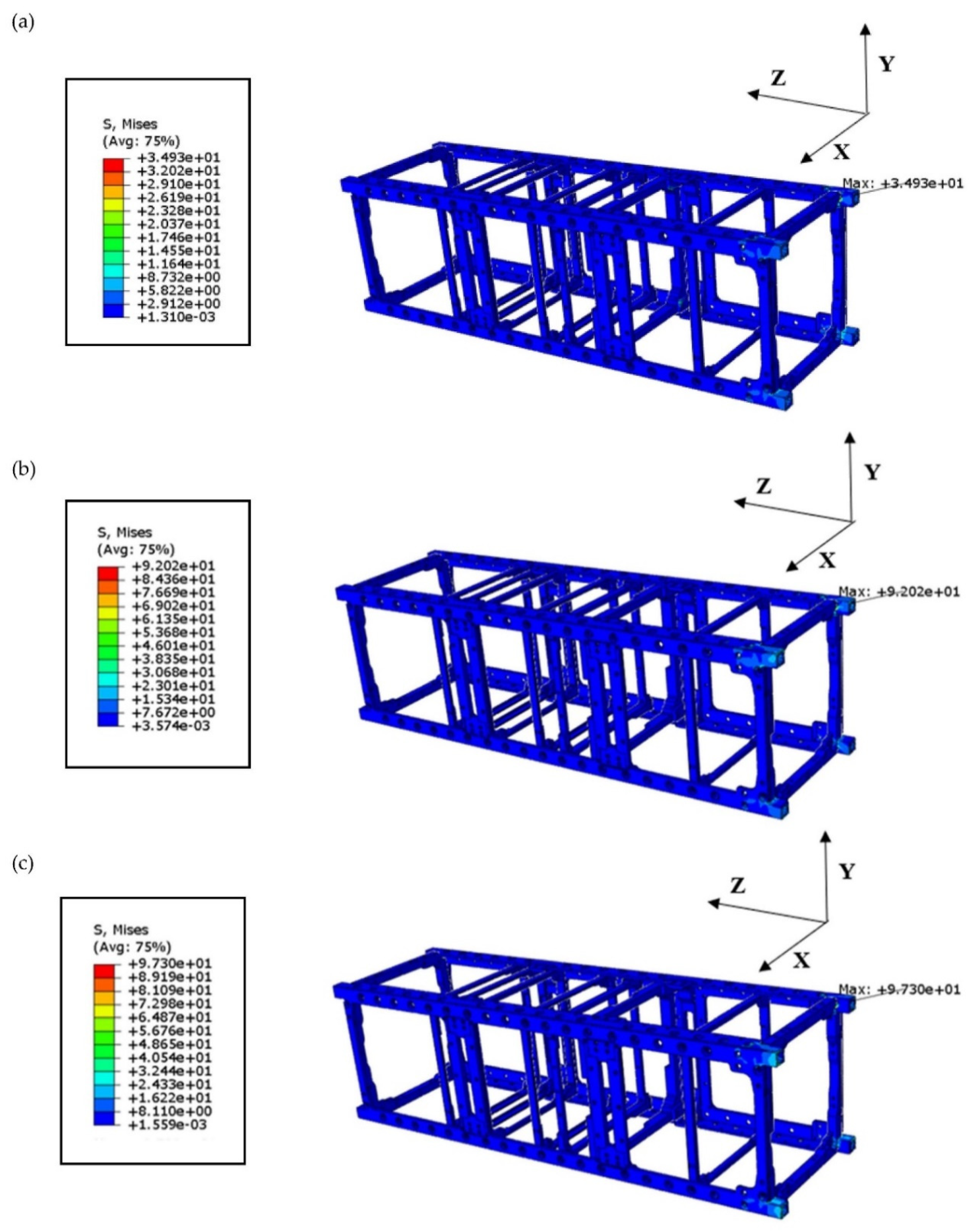
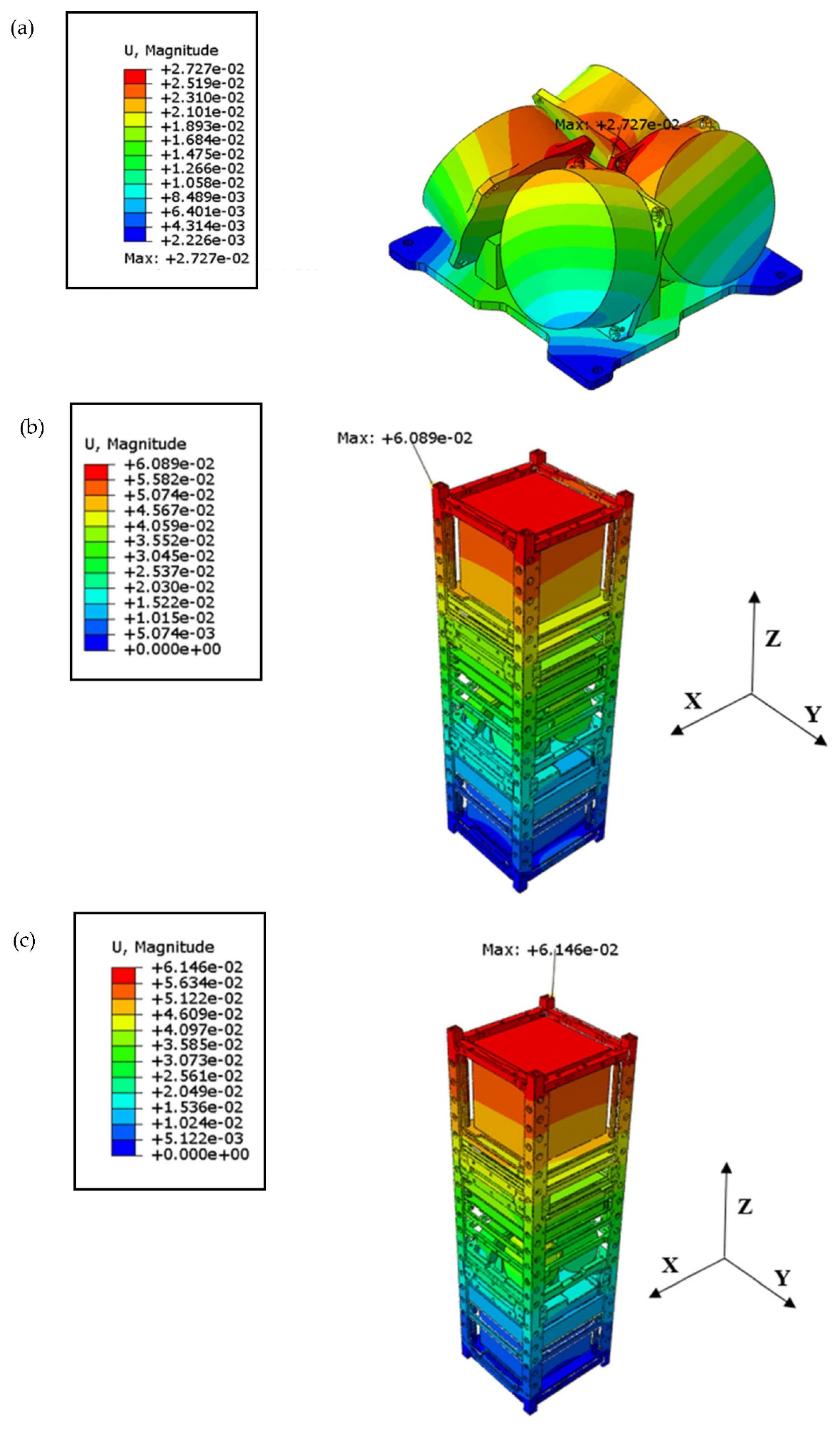
4.7.3. Quasi-Static Analysis

Quasi-static load is independent of time as it varies slowly. In addition, 46.6 N compression load will be applied on each rail at + Z . Table 11 shows the three cases of loading.
The maximum von Mises stress on the satellite was found to be 41.46, 92.02, and 97.3 MPa in analyses A, B, and C, respectively. The maximum deflection on the satellite was 0.027, 0.061, and 0.061 mm in analyses A, B, and C, respectively. Table 12 shows the locations of the maximum von Mises stresses and maximum deformations in each case. Stress levels on various parts of the satellite and deformations are displayed in Figure 14, Figure 15 and Figure 16. The margin of safety ( M S ) for the various components was computed using a factor of safety ( F O S ) of 1.5 for yield strength ( F t y ) and 2.0 for ultimate strength ( F t u ). The following equations were used to calculate the margin of safety. The results are shown in Table 13. All the results were within the safety criteria as shown in the tables below.
M S = a l l o w a b l e   s t r e s s m a x i m u m   s t r e s s × F O S 1 0 ,

4.7.4. Modal Analysis

The analysis in this section is concerned with the dynamic behavior of the structure during launch. The first two natural frequencies were determined to ensure the first natural frequency was above 100 Hz , as is in the requirement of the launcher [3]. The same 3D model used in the quasi-static analysis was used for the modal analysis. According to the obtained results, the frequency of the first mode was 167.87 Hz , which deems the CubeSat structure robust since the frequency is greater than 100 Hz . The reaction wheels are the parts that are deformed during the first mode. Similarly, in the second mode, the reaction wheel is the most deformed part as shown in Figure 17.

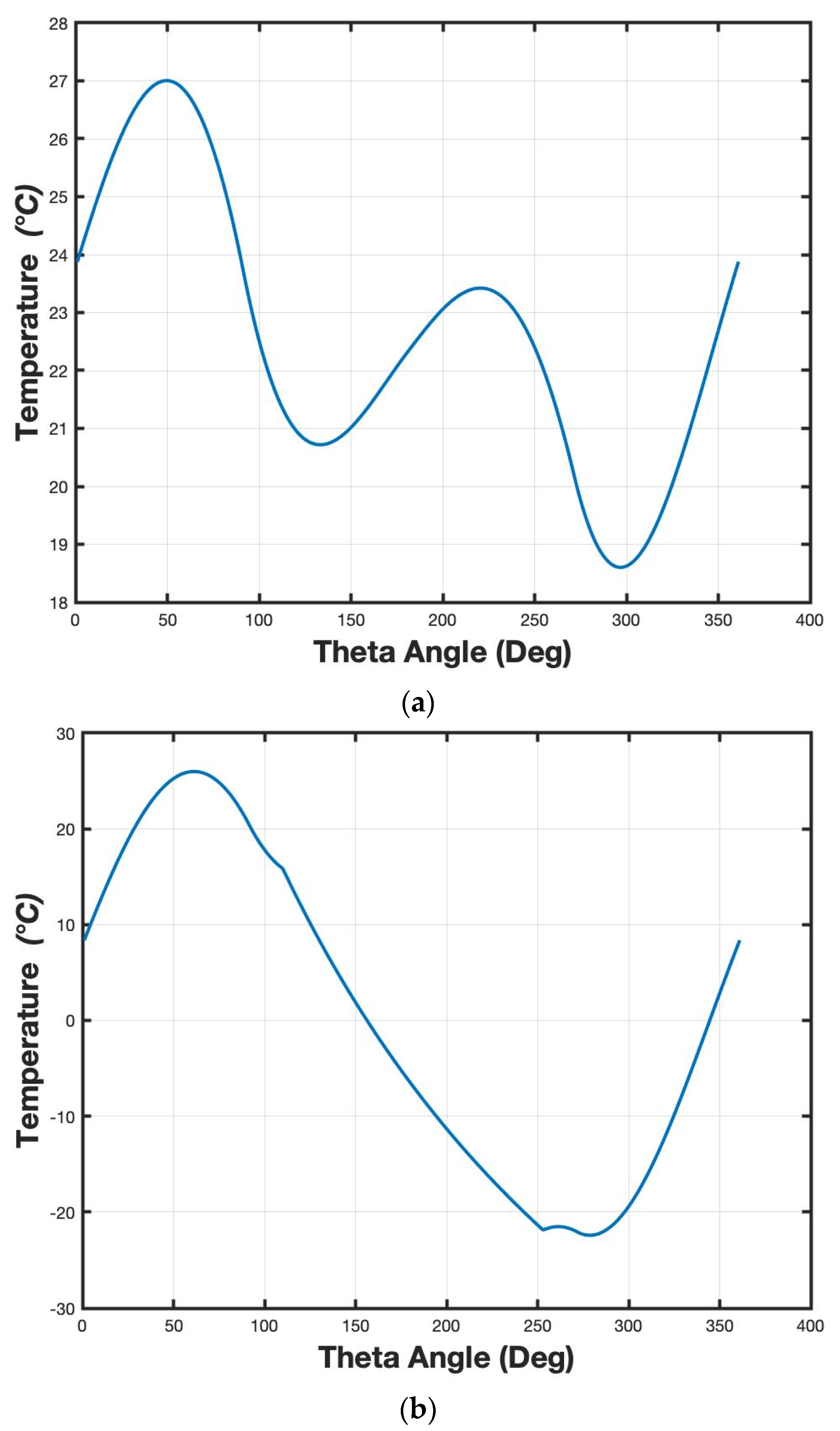
4.8. Thermal Analysis

The objective of the thermal analysis is to ensure that all the electronics and the structure are operating within their allowable temperature ranges throughout the entire mission phase. The thermal analysis for Light-1 was conducted using the CubeSat Wizard, a numerical tool based on MATLAB to estimate the evolution in certain orbital parameters and calculate the heat fluxes [12]. It generates the expected temperature profile for any given date for the CubeSat. The model is based on a single isothermal node approach and considers the orbital parameters as well as the eclipse and the solar illumination cycles on each surface of the CubeSat. In addition, the model includes the effects of the albedo and Earth infrared heat fluxes. For a Nadir pointing attitude and based on the orbital parameters and the CubeSat specifications, we were able to find the critical temperatures by defining the worst hot and cold cases. The worst hot case corresponds to the day in which the average total heat flux from the Sun, albedo, and infrared are the maximum, in which case the eclipse ratio is zero. Thus, the entire orbit will be exposed to sunlight. In contrast, the worst cold case condition corresponds to the case in which the satellite is operated on the day that has the lowest incoming average total heat flux in which the orbit, in this case, is experiencing the maximum eclipse ratio. As a result, a large portion of the orbit will be shadowed by the Earth. Table 14 summarizes the parameters used for the thermal analysis, while the results of the two worst-cases are displayed in Table 15. Figure 18 shows the temperature evolution of Light-1 overtime during the worst hot and cold cases. The temperature is estimated to vary between 18 and 27 °C in the worst hot case and between −21 and 23 °C in the cold case.

5. Testing Plans

It is highly essential for a CubeSat to undergo various types of standard testing procedures before launching into orbit to ensure the CubeSat is well-built to withstand the space and launch environments. Thus, the two main testing protocols are the vibration testing and thermal testing. The vibration testing is performed on the CubeSat to verify the simulation results obtained from the CAD model and observe its state during launch, while the thermal testing is conducted to identify its performance when subjected to space environment. Although the launcher does not require a thermal vacuum bake-out test to be conducted on the flight model of the CubeSat, it will be performed on Light-1 as a safety practice to monitor its performance. As a preliminary step in the testing, a random vibration test and a thermal vacuum bake-out test will be conducted on a mass model of Light-1. Before conducting each testing procedure, a pre- and post-functional test will be performed on the CubeSat to determine if all the subsystems are functioning properly. The testing procedure has been documented in this section.

5.1. Vibration Test

To ensure the CubeSat can withstand the cyclic loading of the launch condition and its effect afterward, the CubeSat will be tested in a simulated launch environment. Vibration tests include a pre-sine sweep followed by random vibration and then a post-sine sweep vibration test on all three axes ( X , Y and Z ) of the CubeSat. The shaker machine setup, which will be used to perform the vibration test, is a low-force shaker LDS V780. The system used is an air-cooled based system, which uses an amplifier to provide amplification for the accelerometer signals.
The same setup can be used to test Light-1 by inserting the model into a 3U test pod, which will be attached to a head expander before mounting it on the shaker plate. For CubeSat sizes greater than 1U, a head expander is needed to mount the test pod with the CubeSat on the shaker due to clearance requirements between the shaker plate and the vibrator structure. Figure 19 below illustrates the head expander and the 3U test pod mounted on it that are manufactured at Khalifa University and will be used to perform the vibration testing on Light-1.
As per Figure 20, the test pod is mounted on one of the axes, which in the figure, is the X axis. Similarly, the test pod will be mounted on the other two axes and a series of sine sweep and random vibrations will be performed. Figure 20 presents the sequence in which the tests will be conducted on Light-1.
After performing the initial functional testing, the sine sweep and random vibration tests will be conducted on the head expander alone, followed by the head expander mounted with the test pod with the Light-1 model on all three axes. The sine sweep vibration profile obtained from QB 50 is defined in Table 16 [14]. The low-level sine sweep will help acquire the CubeSat’s modes of vibration, natural frequencies, damping and mode shapes.
Next, a random vibration will be conducted on the CubeSat using the applicable testing profile based on mission requirements from JAXA. Possible random vibration profiles from the satellite launchers are illustrated in Table 17. The random vibration test on Light-1 will be performed using the HTV testing profile. After the random vibration, another low-level sine sweep will be conducted, and the results obtained from the post-sine sweep will be compared with the pre-sine sweep to observe for any frequency/mode shifts. Finally, after completing all the necessary testing protocols, a functional test will be performed to determine the health status of the CubeSat. If the health check is satisfactory and the required vibration levels have been reached without damaging the CubeSat, the vibration test will be deemed successful.

5.2. Thermal Vacuum Test

The purpose of the thermal vacuum (T-VAC) test is to simulate a space environment to test whether the CubeSat can withstand thermal loading during a series of hot and cold cycles. A thermal bake-out test is performed before shipping the CubeSat to the launcher to remove any volatilities present on the CubeSat. The thermal vacuum test can identify and expose design issues before components are assembled into larger systems. An HVC-3500 thermal vacuum system will be used to perform the T-VAC testing. Usually, the thermal vacuum system operates at high temperatures ranging from −40 to 100 °C, where the system is prepared with a chiller system (LABFREEZ HRHC-635N) to keep the refrigerant cooled during the cold cycles.
The different ranges in temperature shown in Table 18 shall be considered to perform the T-VAC testing for different launch vehicles and conditions. These include the thermal environment of the three possible JAXA launch vehicles [3] inside the ISS and outside the ISS while still in the pod. A preliminary test profile from QB 50 [14] will be used to test the mass model. An arbitrary soak time is assumed, which will be verified after the mass model testing for the actual CubeSat test. In addition, the pressure input for the actual CubeSat test will also be confirmed post the mass model testing.

6. Conclusions

Light-1 is a 3U CubeSat designed to detect and monitor terrestrial gamma ray flashes. The CubeSat will detect TGF events at the ISS orbit at microsecond time granularity, allowing for an unprecedented definition of a TGF typical time structure. If successful, Light-1 will be a pioneering CubeSat for future constellations of small satellites targeting TGFs with extreme spatial and time resolution. The improved knowledge of TGF science will also be beneficial for commercial and military airlines, preventing dangerous and high intensity exposures. Orbital analysis conducted on the CubeSat shows that with the preferred horizontal orientation and an effective drag area of 0.01 m 2 as well as a lifetime of 2.2 years can be achieved, which is considerably greater than the required 6 months for the mission. With the three ground stations in Abu Dhabi, Vilnius, and Aalborg, a collective average access time of 37.14 min / day can be achieved, during which 50 MB of payload data and a generated housekeeping data of 1.04 MB / day can be duly transmitted to the ground stations. The telemetry analysis shows that the margin is closing, which enables good communication with the ground station. A significant mass margin is available for any design changes. Furthermore, the power budget shows a sufficient power profile that can accommodate additional power requirements for CubeSat functioning if required. The attitude determination and control analysis show satisfactory performance of the ADCS system that meets the mission requirements. Finite element analysis conducted shows that the CubeSat can withstand launch conditions and meets the minimum criteria for safety. Finally, the results of the thermal analysis concluded that Light-1 can withstand extreme temperature conditions, i.e., complete sunlight and complete eclipse. Light-1 is currently in its assembly stage and is expected to launch in late 2021 from the International Space Station.

Author Contributions

Conceptualization, F.J., H.A. and P.M.; investigation, B.A. (Basel AlTawil), H.I., P.D. and V.T.; project administration, F.J., H.A. and P.M.; supervision, A.K. (Aaliya Khan) and F.J.; writing—original draft, A.A. (Aaesha Almazrouei), A.K. (Aaliya Khan), A.A. (Abdullah Almesmari), A.A. (Ahmed Albuainain), A.B., A.A.M., A.A. (Ali Alqaraan), A.A. (Alya Alhammadi), A.A. (Amina AlBalooshi), A.K. (Ashraf Khater), A.A. (Aysha Alharam), B.A. (Bashayer Alkhzaimi), E.A., M.T.A., N.A., N.B., R.A. (Reem Alialali), R.A. (Ruqayya Alhammadi), R.A.-h., S.A., S.B. and Y.A.; writing—review and editing, A.K. (Aaliya Khan) and F.J. All authors have read and agreed to the published version of the manuscript.

Funding

This research was funded by the UAE Space Agency, grant number K11-2016-002.

Institutional Review Board Statement

Not applicable.

Informed Consent Statement

Not applicable.

Data Availability Statement

Not applicable.

Acknowledgments

The authors would like to thank the UAE Space Agency, Northrop Grumman, and the Al Yah Satellite Communications Company (Yahsat) for their technical and financial contribution to the progress of the Light-1 project. The authors would also like to recognize the contribution of the National Space Science Agency (NSSA), Bahrain and the collaboration of the payload development team from New York University, Abu Dhabi (NYUAD). In addition, we would like to acknowledge the Kibo Japanese Experiment Module (JEM) and NanoAvionics teams for their continuous support and cooperation with the Light-1 assembly and integration.

Conflicts of Interest

The authors declare no conflict of interest.

References

  1. Arneodo, F.; Di Giovanni, A.; Marpu, P. A Review of Requirements for Gamma Radiation Detection in Space Using CubeSats. Appl. Sci. 2021, 11, 2659. [Google Scholar] [CrossRef]
  2. Di Giovanni, A.; Manenti, L.; AlKhouri, F.; AlKindi, L.R.; AlMannaei, A.; Al Qasim, A.; Benabderrahmane, M.L.; Bruno, G.; Conicella, V.; Fawwaz, O.; et al. Characterisation of a CeBr3 (LB) detector for space application. J. Instrum. 2019, 14, P09017. [Google Scholar] [CrossRef] [Green Version]
  3. Japan Aerospace Exploration Agency (JAXA). Small Satellite Deployment Interface Control Document Version D. In JEM Payload Accomodation Handbook; Japanese Aerospace Exploration Agency (JAXA): Tokyo, Japan, 2020; Volume 8. [Google Scholar]
  4. Osman, I.T. Design and Implementation of Eps (Electrical Power System) of a Cubesat. Ph.D. Thesis, University of Khartoum, Khartoum, Sudan, 2012. [Google Scholar]
  5. Politecnico Di Torino. e-st@r-II Program: Commands and Telemetry. 20 April 2016. Available online: https://www.passion-radio.org/images-blog/Estar2.10_Commands-and-telemetry_Pub_I1_R0.pdf (accessed on 30 April 2020).
  6. AAUSAT-4. Spacelink Format. 21 April 2016. Available online: http://www.space.aau.dk (accessed on 30 April 2020).
  7. MathWorks®. International Geomagnetic Reference Field. Available online: https://www.mathworks.com/help/aeroblks/internationalgeomagneticreferencefield.html (accessed on 17 February 2021).
  8. Alhammadi, A.N.; Jarrar, F.; Al-Shaibah, M.; Almesmari, A.; Vu, T.; Tsoupos, A.; Marpu, P. Effect of Finite Element Model Details in Structural Analysis of CubeSats. CEAS Space J. 2021, 13, 231–246. [Google Scholar] [CrossRef]
  9. MatWeb Material Property Data. Aluminum 7075-T6; 7075-T651. Available online: http://www.matweb.com/search/DataSheet.aspx?MatGUID=4f19a42be94546b686bbf43f79c51b7d (accessed on 27 April 2020).
  10. ASM Aerospace Specification Metals Inc. AISI Type 304 Stainless Steel. Available online: http://asm.matweb.com/search/SpecificMaterial.asp?bassnum=mq304a (accessed on 27 April 2020).
  11. Alhammadi, A.; Al-Shaibah, M.; Almesmari, A.; Vu, T.; Tsoupos, A.; Jarrar, F.; Marpu, P. Quasi-Static and Dynamic Response of a 1U Nano-Satellite during Launching. In Proceedings of the 8th European Conference for Aeronautics and Space Sciences (EUCASS), Madrid, Spain, 1–4 July 2019. [Google Scholar]
  12. CubeSat Wizard. Available online: https://cubesatwizard.com/ (accessed on 11 October 2020).
  13. Martinez, I. Thermo-Optical Properties. Available online: http://webserver.dmt.upm.es/~isidoro/dat1/Thermooptical.pdf (accessed on 1 June 2021).
  14. QB 50. System Requirements and Recommendations Issue 6. 9 July 2014. Available online: https://www.qb50.eu/index.php/tech-docs/category/QB50_system_requirements_issue_606e0.pdf?download=58:qb50-docs (accessed on 27 April 2020).
Figure 1. Modes of operation.
Aerospace 08 00247 g001
Figure 2. Light-1 ground station coverage.
Aerospace 08 00247 g002
Figure 3. System architecture of Light-1.
Aerospace 08 00247 g003
Figure 4. Pin level diagram of Light-1.
Aerospace 08 00247 g004
Figure 5. Light-1 assembly.
Aerospace 08 00247 g005
Figure 6. Distribution of solar cells in each Light-1 solar panel.
Aerospace 08 00247 g006
Figure 7. Light-1 ADCS breakdown.
Aerospace 08 00247 g007
Figure 8. Light-1 Sun horizon pointing mode.
Aerospace 08 00247 g008
Figure 9. Detumbling in initial mode with 17.32 deg / s initial rate on each axis.
Aerospace 08 00247 g009
Figure 10. Quaternion response for (a) Vilnius and (b) Aalborg.
Aerospace 08 00247 g010aAerospace 08 00247 g010b
Figure 11. Angular momentum of the reaction wheels for (a) Vilnius and (b) Aalborg.
Aerospace 08 00247 g011
Figure 12. Simplified model of Light-1.
Aerospace 08 00247 g012
Figure 13. Boundary conditions applied on the rail for (a) quasi-static analysis and (b) modal analysis.
Aerospace 08 00247 g013
Figure 14. Maximum stress (MPa) in frame: (a) Case A; (b) Case B; (c) Case C.
Aerospace 08 00247 g014
Figure 15. Maximum stress ( MPa ) in frame—zoomed: (a) Case A; (b) Case B; (c) Case C.
Aerospace 08 00247 g015
Figure 16. Maximum deformation ( mm ): (a) Case A; (b) Case B; (c) Case C.
Aerospace 08 00247 g016
Figure 17. Modal analysis results: (a) deformation of the first mode and (b) deformation of the second mode.
Aerospace 08 00247 g017
Figure 18. Temperatures that Light-1 can experience based on the thermal analysis: (a) hot case scenario and (b) cold case scenario.
Aerospace 08 00247 g018
Figure 19. Test pod mounted on the head expander.
Aerospace 08 00247 g019
Figure 20. Vibration test sequence.
Aerospace 08 00247 g020
Table 1. Light-1 components.
No.Component
1CubeSat structure
2Payload controller
3Electric power system
4Onboard computer
5Solar panel Z+ PCB (GPS)
6Solar panel Z− PCB (S-band)
7Deployable solar panel
8GPS patch antenna
9S-band patch antenna
10Sun sensor
11Reaction wheels 4W set
12S band transceiver
13GPS receiver
14RF splitter
153- axes magnetorquers
16PMT detector (payload)
17SiPM detector (payload)
Table 2. Light-1 mass breakdown.
S. NoSubsystemComponent Mass   ( g )
1Structure + Platform Bus3U frame634.35
2deployable release mechanism holder
3reaction wheel mount
4EPS shield
5GPS receiver mount
6SiPM payload holder ring
7payload controller
8miscellaneous
9Power SubsystemEPS683.16
10solar panels
11Sun sensors
12Command and Data Handling Subsystemon-board computer124.65
13Attitude Determination and Control Subsystemreaction wheels1057.4
14magnetorquers
15Communication SubsystemGPS patch antenna347.20
16GPS receiver
17 S band patch antenna
18 S band receiver
19RF splitter
20PayloadPMT detector2051.0
21SiPM detector
Total mass ( g )4897.8
Total mass w/5% margin for wiring and harnessing ( g )5040.1
Table 3. Power and energy generated in different modes.
Pointing Mode Power   ( W ) Energy   ( W h )
Nadir 5.3008.170
Sun horizon 10.1215.60
Full Sun Tracking13.1920.33
Table 4. Power consumption of Light-1 during different modes.
Power   Consumption   ( mW ) Normal Mode Duty Cycle (%)Target Pointing Mode Duty Cycle (%)Safe Mode Duty Cycle (%)
EPS165.00100100100
OBC363.00100100100
ADCSFine sun sensors87.1201001000
GPS antenna16.5001001000
GPS receiver145.201001000
M6P magnetorquers (Rod)935.0008.600
X, Y-axis magnetorquers440.0008.600
Z-axis magnetorquers 429.0008.600
4 reaction wheel (steady)660.00100100100
COMUHF TX5808.06.7013.76.70
UHF RX254.10100100100
S-band5500.0012.40
Payload6490.01001000
Total   Energy   Consumption   Per   Orbit   ( m W h )13,20915,0722954.3
Table 5. Light-1 data budget.
Total Downlinked Data Using Minimum Access Time
Downlink rate ( bps )1200240048009600
Total download size ( MB day )0.0600.1100.2300.450
Total Downlinked Data Using Average Access time
Downlink rate ( bps )1200240048009600
Total download size ( MB day )0.1200.2500.4900.980
Table 6. Light-1 UHF link budget.
Uplink Downlink
Maximum Distance ( km )2300
Frequency ( MHz )435
Data rate ( bit / s )2400
Bandwidth ( Hz )14,400
Transmitter power ( dBW )13.973.000
UHF Tx antenna gain ( dBi )12.24−2.000
Cable losses ( dB )2.3100.600
Total losses ( dB )156.2156.14
UHF antenna gain ( dBi )2.03012.90
Line losses ( dB ) 2.3102.410
System Noise Temperature ( K )241.5342.9
EIRP23.900.400
System Eb/No32.4240.27
Required Eb/No14.0018.00
Margin ( dB ) 18.4222.27
Table 7. Light-1 S band link budget at the Vilnius ground station.
S-Band Downlink (Eb/No) Method
Calculating path distance
Earth radius ( Km )63716371637163716371637163716371
Orbit ( Km )400400400400400400400400
Elevation angle (°)05102030405060
Distance ( Km )2292.81803.81439.4984.03739.31598.14511.72457.41
S-band transmitter specifications
Downlink Frequency ( MHz )23002300230023002300230023002300
Data rate ( bit / s )128,000128,000128,000128,000128,000128,000128,000128,000
Bandwidth ( Hz )650,000650,000650,000650,000650,000650,000650,000650,000
S-band Transmitter ( dBW )00000000
S-band antenna gain ( dBi )44444444
Ground station specifications
S-band receiver gain5050505050505050
S-band antenna gain ( dBi )3131313131313131
Line Losses2.312.312.312.312.312.312.312.31
System Noise Temperature230170161156154154154153
Losses
Loss of polarization0.50.50.50.50.50.50.50.5
Atmospheric losses0.70.70.70.70.70.70.70.7
Satellite Cable Losses0.60.60.60.60.60.60.60.6
Free Space Losses ( dBi )166.88164.79162.83159.53157.05155.21153.85152.88
Downlink margin
Satellite EIRP3.43.43.43.43.43.43.43.4
Isotropic Signal @ GS−164.68−162.59−160.63−157.33−154.85−153.01−151.65−150.68
G/T5.076.386.626.756.816.816.816.85
Boltzmann’s Constant ( dBi )−228.6−228.6−228.6−228.6−228.6−228.6−228.6−228.6
Signal to noise power S/No68.9972.3874.5878.0280.5682.4083.7584.77
System Eb/No17.9121.3123.5126.9529.4931.3332.6833.69
Required Eb/No1313131313131313
Margin4.9108.31010.5113.9516.4918.3319.6820.69
Table 8. Input values used to run the detumbling simulation.
InputValue
Moment of Inertia ( kg . m 2 )[9.71 × 10⁻³, −2.80 × 10⁻⁵, −4.86 × 10⁻⁴;
−2.80 × 10⁻⁵, 6.56 × 10⁻², 3.76 × 10⁻⁵;
−4.86 × 10⁻⁴, 3.76 × 10⁻⁵, 6.56 × 10⁻²]
Altitude ( km )400
Inclination ( deg )51.6
Table 9. Input values used to run pointing simulation.
InputValue
Moment of Inertia ( kg . m 2 )[9.71 × 10⁻³, −2.80 × 10⁻⁵, −4.86 × 10⁻⁴;
−2.80 × 10⁻⁵, 6.56 × 10⁻², 3.76 × 10⁻⁵;
−4.86 × 10⁻⁴, 3.76 × 10⁻⁵, 6.56 × 10⁻²]
Initial attitude (Quaternions)[1 0 0 0]
Desired attitude (Quaternions)[0.0001 0.2754 0 0.9613] (Aalborg worst attitude
[0.2592 0.2592 0.0724 0.9276] (Vilnius worst attitude)
[0.2021 0.6959 0.2148 0.6548] (Full Sun tracking worst attitude)
[0.9924 0.0868 0.0868 0.0076] (Sun horizon worst attitude)
Proportional gain (Kp)0.001
Derivative gain (Kd)0.0055
Initial angular rate ( deg / s )[0 0 0]
Environmental disturbances ( Nm ) [−3.0255 × 10⁻⁷ −3.5739 × 10⁻⁵ −3.2116 × 10⁻⁹]
Table 10. Material properties [9,10,11].
Part Mass   ( g ) Volume   ( c m 3 ) Average   Density   ( g / c m 3 ) Young s   Modulus   ( MPa ) Poisson’s Ratio
Frame --2.8171,7000.330
Rods --8.00200,0000.290
Spacers --8.00200,0000.290
Reaction wheels642.001773.6224,0000.136
Magnetorquers205.0094.32.1724,0000.136
S-band Receiver190.001021.8724,0000.136
GPS Receiver50.00038.41.3024,0000.136
EPS194.0053.23.6524,0000.136
On-board Computer103.2129.53.5024,0000.136
Payload controller PCB53.38023.92.2324,0000.136
Payload 11130.04542.4924,0000.136
Payload 2942.003452.7324,0000.136
GPS patch antenna36.0006.355.6724,0000.136
S-band patch antenna60.90027.12.2524,0000.136
Table 11. Quasi-static analysis loads.
LoadX axisY axisZ axis
Analysis A
Compressive ( N )--46.6
Static ( G )9--
Analysis B
Compressive ( N )--46.6
Static ( G )-9-
Analysis C
Compressive ( N )--46.6
Static ( G )--9
Table 12. Maximum stresses and deformations in each case.
Load Along X
Case A
Load Along Y
Case B
Load Along Z
Case C
MaxLocationMaxLocationMaxLocation
Von Misses stresses ( MPa )41.16reaction wheels board92.02Al frame97.3Al frame
Deflection ( mm )0.027reaction wheels0.061Al frame0.061Al frame
Table 13. Factor of safety.
PartMaterial Max   Stress ,   S m a x   ( MPa ) Yield   Strength   ( MPa ) Ultimate   Strength ,   F t u   ( MPa ) YieldUltimate S m a x / F t u   < 30   [ % ]
M S ≥ 0
F O S = 1.5
M S ≥ 0
F O S = 2
Analysis A
FrameAl 7075-T65134.935025858.5807.3705.970
RodStainless steel11.8320551510.5520.772.290
SpacersAl 7075-T6519.98050258532.2528.311.710
Reaction wheels boardFR-441.16-310-2.7713.28
Analysis B
FrameAl 7075-T65192.025025852.6402.18015.73
RodStainless steel11.8620551510.5220.712.300
SpacersAl 7075-T65112.1950258526.4522.992.080
Reaction wheels boardFR-472.08-310-1.13023.25
Analysis C
FrameAl 7075-T65197.305025851.8602.01016.63
RodStainless steel11.8320551510.5520.772.290
SpacersAl 7075-T65110.9850258529.4825.641.880
Reaction wheels boardFR-449.50-310-2.13015.97
Table 14. Light-1 thermal analysis parameters.
ParameterValue
Mass5.22   kg
Inclination anglei = 51.6°
Surface area average emissivity, ε0.8 [13]
Surface area average absorptivity, α0.8 [13]
Specific heat, C p 470 J / kg ° K
Albedo constant0.3
Generated heat from the electronics2 W
Planet temperature288 °K
Table 15. Thermal analysis worst case results.
Hot CaseCold Case
Estimated date11-December-202126-May-2022
Beta angle−71.3°−0.27°
Temperature 27 °C−21.0 °C
Table 16. Low-level sine sweep test profile [3].
Frequency   ( Hz ) Amplitude   ( G ) Sweep   Rate   ( Oct / min )
10–20000.51
Table 17. Possible random vibration testing profiles [3].
HTVDragonCygnus
Frequency   ( Hz ) PSD   ( g 2 / Hz ) Frequency   ( Hz ) PSD   ( g 2 / Hz ) Frequency   ( Hz ) PSD   ( g 2 / Hz )
200.005200.02200.004
500.022000.02300.004
1200.03120000.001700.015
2300.031 1500.015
10000.0045 20000.0006
20000.0013----
Overall (grms)4.05Overall (grms)3.2Overall (grms)2.44
Duration (s)60Duration (s)60Durations (s)60
Table 18. Light-1 thermal vacuum test conditions [3].
Thermal Test Environments Temperature   Ranges   ( ° C )
HTV+5~+32
Dragon+18.3~+29.4
Cygnus+10~+46.1
Inside the ISS+16.7~+29.4
Outside the ISS (when the satellite is inside the J-SSOD)−15~+60
Publisher’s Note: MDPI stays neutral with regard to jurisdictional claims in published maps and institutional affiliations.

