Abstract
This study employs computational fluid dynamics (CFD) to investigate the aerodynamic performance and static stability of hybrid wing aircraft, considering the interference of counter-rotating embedded propellers. Extensive numerical verification has been carried out, including comparisons with NASA’s high-lift propeller (HLP) data. Three configurations—no propeller, counter-rotating inboard-upwash (CNIU) and counter-rotating outboard-upwash (CNOU) are defined to analyze the aerodynamic force/moment characteristics and flow field structures over a range of angles of attack from −6° to 26°, in conjunction with crosswind velocities of 0, 5, 10, and 15 m/s. The propeller-induced slipstream alters the aircraft’s fundamental performance by modifying wing pressure distributions and vortex systems. Specifically, the CNIU configuration increases the low-pressure areas on both the fuselage and outer wing upper surfaces, enhancing the lift-to-drag ratio by 28.4% at low angles of attack. In contrast, the CNOU configuration improves longitudinal steady-static margin by 27.4% under typical conditions and demonstrates superior lateral static stability under 10 m/s leftward crosswind conditions. For engineering applications in the aerodynamic design of such aircraft, the CNIU configuration is recommended for high cruise efficiency, whereas the CNOU configuration is preferred for flight stability.
1. Introduction
As an emerging platform for urban air mobility (UAM), electric vertical take-off and landing (eVTOL) aircraft enable efficient aerial transportation within and between cities, and are regarded as an innovative approach to improving the networks of future transportation [1]. The hybrid wing configuration refers to an aircraft that combines the features of both the fixed-wing and multi-rotor. Categorized by propulsion configurations, it can be divided into multi-rotor, tilt-rotor/wing, lift-cruise hybrid and tail-sitter [2]. These diverse configurations are explored to achieve a balance between vertical take-off and landing capability and efficient cruise performance. However, aerodynamic interactions generated by propellers and airframe components constrain the enhancement in aerodynamic performance and the flight stability of the whole aircraft [3].
The blended-wing-body (BWB) configuration offers higher aerodynamic efficiency and structural strength. It also offers advantages in economy and environmental friendliness compared to conventional configurations, which is a significant development direction for future green aviation [4,5]. Experimental and simulation studies have shown that the BWB configuration can achieve an increment in aerodynamic characteristics compared to traditional ones like delta wings [6]. Zhang et al. [7] enhanced both the aerodynamic and infrared stealth performance of airfoils resembling the X-47B shape through optimization design. Qin et al. [8] applied a multidisciplinary design optimization approach to a BWB shape, achieving further improvements in aerodynamic characteristics. The BWB configuration enhances the aerodynamic efficiency of the whole aircraft by reducing the interference drag. Nevertheless, its inherently blended design of the fuselage and wings limits the fuselage volume expansion and consequently reduces the available cargo payload capacity. The potential deployment of the BWB configuration’s unique advantages in hybrid wing aircraft still needs to be further explored.
Although the BWB configuration has favorable aerodynamic performance, the conventional tail is eliminated, resulting in poor longitudinal and lateral–directional stability [9,10]. Wang et al. [11] proposed a three-axis coupled flight control design method. Employing the split drag rudders, the Dutch roll mode damping of a flying-wing configuration is enhanced by 30%. Song et al. [12] analyzed the dynamic stability of a tailless flying wing aircraft based on the vortex lattice method and small-disturbance equations, achieving an optimization design close to Level 2 flying qualities. However, significant progress has been made in the aerodynamics and stability of BWB aircraft. The specific interactions of propulsion systems should be assessed for eVTOL aircraft design. Furthermore, in real flight conditions, crosswinds can induce asymmetric aerodynamic loads, generating additional rolling and yawing moments that affect aircraft stability and controllability [13]. Research by Ryu et al. [14] on a ducted fan unmanned aerial vehicle (UAV) indicated that the flow separation and distortion at the lip of the duct is induced by the crosswind velocity. Additionally, unsteady numerical analysis revealed that crosswind interference can lead to periodic fluctuations in the thrust of ducted fan, and flow instability can be triggered when the wind speed exceeds a specific threshold [15]. Such issues pose challenges to the flight stability of hybrid wing aircraft.
The interaction between the propulsion system and the airframe constitutes a critical issue in the BWB configuration design. Zhao et al. [16] evaluated the aerodynamic-propulsive interference on a BWB aircraft with a distributed propulsion (DP) system. The high-speed inflow from the DP system increased the viscous dissipation rate in the boundary layer, enhancing the cruise and maximum lift coefficient by 13% and 47%, respectively. Wang et al. [17] also conducted optimization research on a similar scheme, achieving a maximum lift-to-drag ratio of 22.31 for the whole aircraft. Consequently, the interference of the propulsion system on the aerodynamic performances of BWB aircraft is significant. However, equipping a BWB aircraft with vertical take-off and landing capabilities requires specialized propulsion systems, such as tilt-rotors/wings [18], tail-sitter [19], embedded co-axial rotors [20], and embedded quad-rotors [21]. Liu et al. [22] focused on the transition flight of a tandem multi-rotor aircraft, thereby uncovering the physical interference mechanism of the external propeller slipstream. Wu et al. [23] demonstrated center-of-mass trimming for a tandem-wing eVTOL aircraft capable of operating with external ducted fans. Wang et al. [24] performed orthogonal optimization on the installation of embedded symmetric dual rotors, achieving enhancement in aerodynamic efficiency.
Balancing computational cost and efficiency in the solution methodology poses a challenge for the aerodynamic analysis of propeller–aircraft interactions. Liang et al. [25] applied the multiple reference frame (MRF) method to investigate the interaction between the propeller and the wing of a tail-sitter aircraft. Both Arumugam et al. [26] and Figat et al. [27] studied the propeller and fuselage aerodynamic interaction, adopting the MRF approach. These studies collectively demonstrate that the MRF approach can effectively address the requirements of the aerodynamic interactions between the propeller and airframe. Compared to unsteady methods such as the sliding mesh model (SMM), the MRF approach maintains better computational efficiency, despite certain limitations in predicting complex vortex interactions and achieving accurate turbulence resolution [28].
Embedded propulsion systems allow propellers or ducted fans to be installed within the aircraft wings or airframe. It has been indicated that this propulsion system requires significantly less safe flight space than quadrotors or helicopters, enabling close-proximity operations near targets or obstacles, which is suitable for flying in complex environments [29]. Engineering applications for embedded propulsion systems are now available. The Project Zero aircraft [30], developed by AgustaWestland, utilized an embedded symmetric ducted fan configuration combined with wings to balance vertical take-off and landing capabilities and cruise performance. Embedded propellers with wings have also been utilized by the TURAC VTOL UAV [31] and ATEA VTOL aircraft generated by Ascendence. Cypher II employs an embedded ducted fan to generate lift for hovering flight and can carry a 20 kg payload over a distance of 185 km [32]. Nevertheless, as a major source of drag, the cruising efficiency of the aircraft is reduced by the cylindrical duct. When isolated propellers are embedded within the wing, the interaction between the propulsion system and the flow field around the aircraft becomes more complex. Therefore, exploring various propulsion patterns is crucial for realizing their aerodynamic interactions in aircraft with embedded propellers.
This paper innovatively proposes a hybrid wing aircraft based on a tail-less high-wing configuration with embedded propellers. Numerical simulation studies are conducted for diverse propulsion patterns to evaluate their aerodynamic characteristics. Particularly, as research on aircraft under crosswind conditions is currently scarce, this paper also investigates the static stability of the hybrid wing aircraft under the interference of crosswinds.
2. Methodologies and Definition
2.1. Numerical Simulation Methods
The characteristics of the flow field are typically analyzed using computational fluid dynamics (CFD), a widely adopted method due to its accuracy and flexibility. Given the trade-off between computational cost and accuracy, the Reynolds-averaged Navier–Stokes (RANS) method is chosen for time-averaged and periodicity analysis. The equation is shown in Equation (1). According to the conservation laws of momentum, the second derivative of momentum with respect to time in a small flow unit is equivalent to the external force acting on it.
To evaluate the propulsive performance of the propeller, thrust coefficient (CT) and torque coefficient (CQ) are computed as shown in Equations (2) and (3), where T denotes the thrust (N), M denotes the torque (N·m), and ρ, n, and D represent the air density (kg/m3), rotating speed (rev/s), and diameter (m) of the propeller, respectively [33]. The working state of the propeller is quantified by the advance ratio (J), calculated as shown in Equation (4), where V represents the freestream velocity.
The aerodynamic performance of the propeller and aircraft is numerically investigated using ANSYS 2019 R1 FLUENT. The SST k-ω turbulence model is employed to resolve near-wall boundary layer flows, providing enhanced predictive accuracy in adverse pressure gradient scenarios. The transport equations of k and ω in the turbulence model are descripted in Equation (5) and Equation (6), respectively. A pressure-based coupled algorithm is used to solve the pressure–velocity coupling equations, enabling simultaneous convergence of the continuity, momentum, and turbulence transport equations. This approach improves solver robustness and numerical precision when handling complex flow separations. The spatial discretization uses a second-order upwind scheme for momentum and turbulence quantities, balancing computational efficiency with solution accuracy.
To address the computational challenges posed by propeller rotation, the MRF approach is applied to the simulation of rotational flow. The MRF is a quasi-steady CFD technique that is widely employed for the aerodynamic performance analysis of rotating devices in research and engineering. The core principle of it involves dividing the computational domain into two distinct regions—a rotating region that encloses the propeller and a steady region that contains the far-field and static components. These regions are connected through the interface; rotational effects are simulated by transferring flow information across the interface while the physical geometry of the propeller remains fixed. The non-inertial frame effects (Coriolis and centrifugal accelerations) are addressed by incorporating corresponding source terms of force into the governing equations of fluid cells within the rotating domain. This formulation of additional source terms is added into the momentum equation (as shown in Equation (1), where the equivalent source term (Si) is given by Equation (7). By integrating relative velocity and volumetric source terms, the stationary mesh is enabled to simulate the fluid dynamic characteristics of a rotating flow field. For further details on the MRF method can be found in reference [34].
2.2. Models Definition
The model of hybrid wing aircraft investigated in this study adopts a tail-less high-wing configuration. The aircraft incorporates a blended transition design at the wing–fuselage junction, similar to the BWB configuration. To enhance the aircraft’s cargo transport capabilities, the fuselage volume has been enlarged, while the design of wing-to-fuselage transition also helps with the reduction in interference drag. Open propellers can provide higher cruise efficiency than ducted fans [35]. The propulsion system consists of two counter-rotating propellers embedded within the wing structure, enabling transition flight between vertical and cruising modes through propeller tilt control. A constant-pitch propeller with a diameter of 0.56 m and five blades is proposed. A three-dimensional form of the aircraft is provided in Figure 1, featuring wingtip-mounted winglets to reduce induced drag during cruise flight. The embedded propulsion system is also depicted in the image, which mainly includes support boom (for mounting the propeller nacelle and motor), the propeller, and a tilt servo. The propeller tilt angle can be adjusted through these components built into the wing, thereby facilitating transition flight. It should be noted that these support structures are omitted during the CFD process to improve the robustness of the numerical simulation. A similar operation was adopted by Walvekar et al. on the aerodynamic interactions of propeller-driven aircraft [36]. The hybrid wing aircraft geometry is parameterized using CATIA V5 R21 software. The main geometric parameters are summarized in Table 1. This configuration is designed to optimize aerodynamic efficiency while maintaining structural compactness for UAM missions.
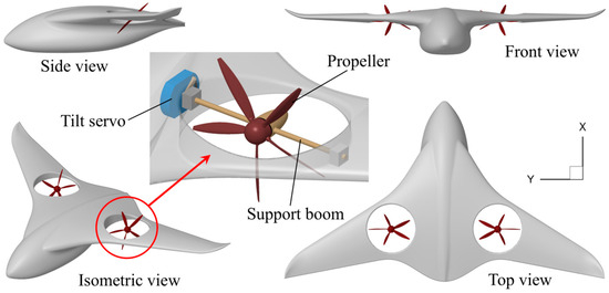
Figure 1.
Geometric model of the hybrid wing aircraft.

Table 1.
Model parameters of the hybrid wing aircraft with embedded propellers.
To systematically characterize the propeller configurations of different models and investigate the effects of varying propeller rotation combinations on aerodynamic characteristics and flight static stability, three representative configurations are defined:
- No propeller configuration: The hybrid wing aircraft without propellers, featuring only empty circular holes in the wing;
- Counter-rotating outboard-upwash (CNOU) configuration: The outer wing is washed up by the slipstream (shown in Figure 2a);
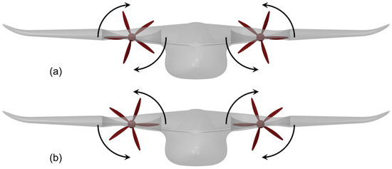 Figure 2. Definition of different rotating directions of propellers (front view). (a) CNOU configuration; (b) CNIU configuration.
 - Counter-rotating inboard-upwash (CNIU) configuration: The inner wing is washed up by the slipstream (shown in Figure 2b).
During cruising flight modes, the propellers generate horizontal thrust for forward flight. The classification of these models is based on reference [37]. This study focuses exclusively on the cruise-phase aerodynamic behavior, with vertical and transition modes explicitly excluded from the current analysis.
3. Verification and Validation
3.1. Mesh Independence Study
The computational domain is discretized using an unstructured finite-volume mesh generated with ANSYS 2019 R1 FLUENT-Meshing software. To satisfy the near-wall resolution requirements of the SST k-ω turbulence model, the dimensionless wall distance (y+) is maintained at approximately 1 across all aerodynamic surfaces, as shown in Figure 3. The freestream velocity (V∞) is set to 30 m/s (Re = 1.5 × 10⁶), with the propeller advance ratio fixed at J = 0.89. Aerodynamic force/moment coefficients and flow-field characteristics are analyzed over an angle of attack (AOA) range from −6° to 26°, combined with crosswind velocities of 0, 5, 10, and 15 m/s to evaluate lateral and directional static stability.
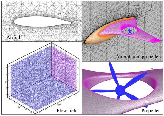
Figure 3.
Unstructured finite-volume fluid mesh generated.
A mesh independence study is conducted to verify the numerical accuracy. The deviations in lift coefficient (CL) and drag coefficient (CD) for the baseline configuration decrease from 3.16% to 0.87% and 2.73% to 1.02%, respectively, as mesh density increases. A final mesh configuration containing 4.2 million elements is selected for subsequent simulations, balancing solution precision and computational cost. The results of the mesh independence verification are summarized in Table 2, confirming the mesh’s adequacy for capturing critical flow features such as boundary layer transitions and vortex shedding.
Table 2.
Mesh independence study of the hybrid wing aircraft (α = 0°).
3.2. Validation of Flow Field
The propellers in the hybrid wing aircraft operate at high rotational speeds, generating significant velocity gradients between the blade root and tip regions, thus imposing stringent requirements on the numerical simulation methodologies. A high-fidelity propeller model is essential for the accuracy of this study. The design and modeling of propellers are typically accomplished through parametric methods, with primary design parameters including blade element airfoils, chord lengths, and twist angles. To validate the reliability of the propeller modeling approach, simulation methodology, and computational results, the high-lift propeller (HLP) from NASA’s Maxwell X-57 project is employed, which shares similar characteristics with the propeller described in Section 2.2. The HLP (D = 0.576 m) have five blades, featuring a trailing edge thickness of 0.02 inches. Each blade has a constant MH114 airfoil from blade root to tip. The pitch angle at a 75% radial position is β = 27.4°, and the distributions of chord, rake, skew, and twist angle along the various radial positions follow the definitions provided in [38]. Employing the CATIA software, the 3D geometry of HLP is generated (as shown in Figure 4). Based on the MRF approach, the fluid field has been divided into a steady region and a cylindrical rotating region containing the HLP blades. The rotating region is set to maintain the same rotational velocity related to the rotor.
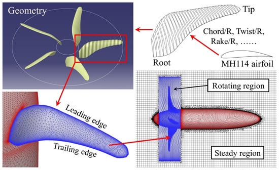
Figure 4.
Process of propeller blades modeling and mesh generation.
Under the 29.84 m/s freestream velocity, the basic propeller performances across various advance ratios are validated. Figure 5a presents the thrust and torque coefficient for the HLP model against numerical reference values [39], demonstrating the thrust mean deviation of 4.7% and the torque mean deviation of 4.9% across multiple advance ratios. Additionally, the slipstream velocity distributions are validated under the condition of 4145 RPM rotational speed and 38.58 m/s freestream velocity (J = 0.97). Figure 5b illustrates the slipstream axial and tangential velocity distributions at 1 R downstream of the propeller, where the experimental data are sourced from NASA [40]. It is observed that the curve demonstrates a relatively smooth and uniform axial velocity distribution from r/R = 0.4 to r/R = 0.8, which fulfills the design intent of the HLP. However, deviations are demonstrated near the r/R = 0.35, which is approximately 8.9%. This is caused by the wall effect from the propeller hub and nacelle. Similar phenomena are also observed in the experiments [40]. In summary, these quantitative comparisons and flow field analyses collectively validate the reliability of the propeller modeling methodology and numerical approach employed in this study.
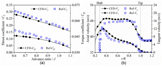
Figure 5.
Characteristics comparison of HLP and slipstream. (a) Performance of propeller; (b) velocity distribution of slipstream.
4. Results and Discussion
4.1. Analysis of Various Propeller Counter-Rotating Patterns
A comparative analysis of the aerodynamic force and moment characteristics was conducted across the three configurations under varying angles of attack. As shown in Figure 6a, the lift coefficient is significantly affected by the propeller rotation patterns. The CNIU configuration demonstrated superior lift characteristics at low angles of attack, with an increment in the slope of the lift-AOA curve by approximately 8.39%, compared to the no propeller configuration. Although the CNOU configuration exhibits a 14.6% lower lift coefficient compared to the CNIU configuration at low AOA, it demonstrates superior lift characteristics at high AOA, at the cost of increased drag. Figure 6b presents the variation in drag coefficient with AOA. It can be observed that the drag coefficients of the configurations with embedded propellers are significantly higher than the no propeller configuration, which is attributed to the strong dynamic pressure effect of the propeller slipstream. Notably, the CNIU configuration exhibits a lower drag coefficient compared to the CNOU, and this phenomenon becomes more pronounced as the angle of attack increases. Therefore, as the embedded propellers interact, the drag of the whole aircraft is increased, while providing a measurable lift benefit. Moreover, the aerodynamic performance of the CNIU configuration is superior to that of the CNOU.
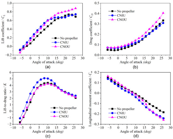
Figure 6.
Comparison of basic performance of the aircraft: (a) CL-AOA; (b) CD-AOA; (c) K-AOA; (d) Cm-AOA.
The lift-to-drag ratio (K) is found to be improved by 28.4% at low angles of attack for the CNIU configuration (Figure 6c). It can be indicated that the maximum K is near the AOA = 6 deg and it is defined as the cruise flight angle of attack. Although mid-wing mounted tiltrotors can degrade cruise efficiency, the CNIU configuration achieved a substantial improvement in lift-to-drag ratio compared to both the CNOU and no propeller configurations. The longitudinal moment coefficient curves for the CNOU and the no propeller configuration intersect near the cruise angle of attack (Figure 6d). Furthermore, the longitudinal static stability (Cm-AOA) for the CNOU configuration was found to be superior, with a steeper slope observed in its longitudinal moment coefficient curve. The 27.4% improvement in longitudinal steady-static margin compared to the no propeller configuration are investigated with regard to the angles of attack for cruise flight. However, under high-AOA flight states, the slope of the longitudinal moment curve for the embedded-propeller configuration exhibits greater variation than that of the no propeller configuration. This is due to the unstable pressure pulsations induced by the propeller slipstream. The CNIU configuration offers superior cruise efficiency, as also observed by Chirico et al. [41] in their research on a turboprop aircraft. Conversely, the CNOU configuration shows enhanced longitudinal static stability characteristics under typical flight conditions.
4.2. Slipstream Interaction Analysis of the Aircraft
In order to explore the aerodynamic interactions of the distinct propeller rotation configurations, a comparative analysis of surface pressure distributions and streamline patterns is conducted. As shown in Figure 7a, the embedded holes disrupt the original pressure distribution on the wing surfaces, causing the low-pressure region to be discontinuous. This is a key reason for the reduction in lift-to-drag ratio observed in Figure 6c. According to research by Sawaqed et al. [42], even though the wing aera is reduced by the embedded holes, certain design modifications to the hole shape could achieve an improvement in lift-to-drag ratio and less turbulent effects. Furthermore, studies by Hoeveler et al. [43] observe that a step on the lower side of the wing in front of the embedded propellers improves the lift-to-drag ratio of the whole aircraft by up to 25%. It is also indicated that this research still has certain significance in engineering applications.
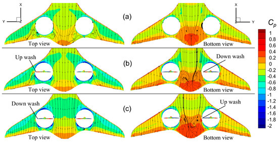
Figure 7.
Aerodynamic pressure coefficient contours and streamlines of the aircraft. (a) No propeller configuration; (b) CNOU configuration; (c) CNIU configuration.
The propeller-deployed configurations have a significant impact on the pressure distribution of the aircraft. As illustrated in Figure 7, both the CNIU and CNOU configurations resulted in expanded low-pressure areas on the upper surfaces of the outer wing sections. The high-pressure regions on the corresponding lower surfaces are similarly enlarged compared to the no propeller configuration. The characteristic of the enhanced low-pressure area over the outboard wing sections explains why the lift of the embedded-propellers configuration is consistently higher than that of the no propeller configuration, as shown in Figure 6a at low AOA. However, the low-pressure region on the upper surface of the airframe in the CNIU configuration is significantly expanded, while the corresponding high-pressure region on the lower surface is also enhanced compared to the CNOU. The CNIU configuration induced additional pressure differentials, thereby enhancing its lift-generating characteristics. From this perspective, the CNIU configuration has more outstanding cruising lift characteristics.
Further analysis of the velocity distribution of the flow field around the aircraft can clarify the causes of the pressure characteristics. Figure 8 presents contours of the crossflow velocity (Y-velocity) in a cross section located 0.5 R downstream of the propeller. It can be observed that, in the absence of propeller influence, significant crossflow velocities are present near the wingtip and the sidewalls of the embedded holes (as shown in Figure 8a). The rotational effect and strong dynamic pressure characteristics of the slipstream generated by the embedded propeller can alter the cross-flow velocity distribution over the upper surface of the wing. For the CNOU configuration, the flow impingement on the fuselage upper surface is induced by the merging of the original crossflow and the propeller slipstream (as shown in Figure 8b). In contrast, the CNIU configuration exhibits significant vortex cancelation between the slipstream and the crossflow on the upper wing surface, which reduces the peak of crossflow velocity (as shown in Figure 8c). However, on the lower wing surface, the CNIU configuration generates higher crossflow velocity than the CNOU, potentially leading to stronger pressure fluctuations.
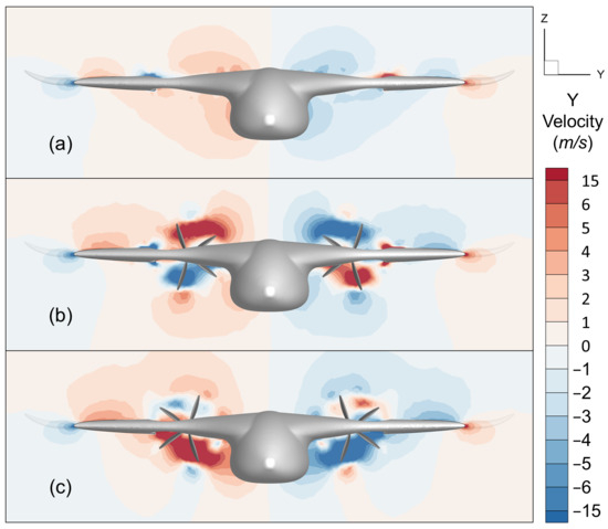
Figure 8.
Crossflow velocity counter of cross section at 0.5 R rear the propeller. (a) No propeller configuration; (b) CNOU configuration; (c) CNIU configuration.
Figure 9 illustrates the distribution of crossflow velocity in the flow field around the aircraft. In particular, Figure 9a shows the lateral flow characteristics near the fuselage, where the front and rear regions exhibit opposite flow directions of the lateral velocity. It is induced by the aerodynamic interactions between the rear-fuselage contraction and the embedded holes. Similarly to Figure 8, the crossflow velocity of upper surface is lower in the CNIU configuration compared to the CNOU. For the CNOU configuration, the flow on the lower surface expands outward, while the flow on the lower surface expands inward and exhibits higher crossflow velocity for the CNIU configuration, which is consistent with the tangential velocity vector of the propeller slipstream. Furthermore, due to the effect of the embedded propellers and the tapered rear fuselage, the CNIU configuration presents an obvious crossflow velocity on the aircraft lower surface, whereas the CNOU is significantly visible on the upper surface. The pressure distribution on the aircraft surfaces is affected by the deviations in crossflow velocity distribution, thereby influencing the lift characteristics of the whole aircraft.
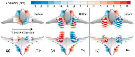
Figure 9.
Crossflow velocity distribution of flow field surrounding the aircraft. (a) No propeller configuration; (b) CNOU configuration; (c) CNIU configuration.
To more accurately capture the variations in aerodynamic characteristics resulting from deviations in velocity distribution, the spanwise aerodynamic load distribution of the aircraft at the cruise angle of attack was analyzed. It is obvious that the sectional lift of CNIU and CNOU configuration is higher than the no propeller configuration in Figure 10a, which is consistent with those in Figure 6a. Meanwhile, the drag characteristics in Figure 10b also align with Figure 6b, confirming the reliability of these results. It is noteworthy that the lift deviations between the CNIU and CNOU configurations are smaller on the outboard wing, while a more significant lift deviation occurs in the central airframe region, which confirms the findings in Figure 7. Additionally, for the no propeller configuration, the wing area is reduced by the embedded holes, and the resulting local lift loss extends to wing regions beyond the hole aera. In contrast, the CNIU and CNOU configurations mitigate the spread of this local lift loss, preserving the lift characteristics of the outboard wing. There are still some details in these results that can help to explain the phenomena presented in Figure 8 and Figure 9. As shown in Figure 10b, drag peaks occur in the propeller upwash regions in both the CNIU and CNOU configurations. Due to the wall effect, a significant drag peak appears in the embedded hole region adjacent to the airframe, whereas the drag increment in the region proximal to the outboard wing is relatively lower, which is particularly pronounced in the CNIU configuration.
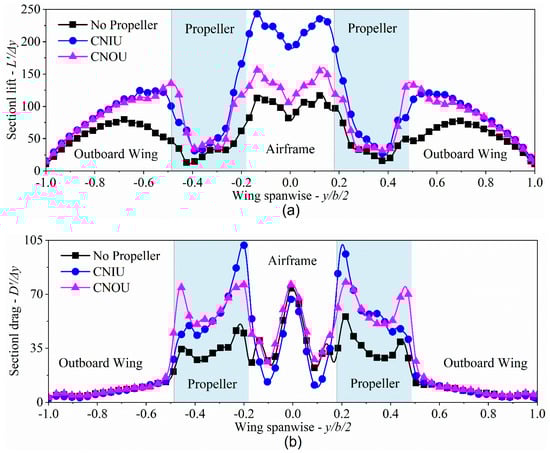
Figure 10.
Sectional aerodynamic force distributions along the wing spanwise (b = 500Δy). (a) Sectional lift; (b) sectional drag.
4.3. Aerodynamic and Stability Analysis of Crosswind Effects
To systematically investigate the effects of propeller rotation direction on lateral and directional static stability, numerical simulations were conducted, incorporating crosswind effects. As shown in Figure 11, the center of gravity of aircraft is defined with the positive crosswind direction corresponding to rightward airflow, which is referenced from [44]. The AOA = 6° is defined as the ideal cruise flight phase in this study of crosswind effect, which corresponds to the maximum lift-to-drag ratio. Computational results confirmed that the aircraft exhibited inherent lateral and directional static stability under crosswind-free conditions, with zero lateral–directional moment coefficients observed.
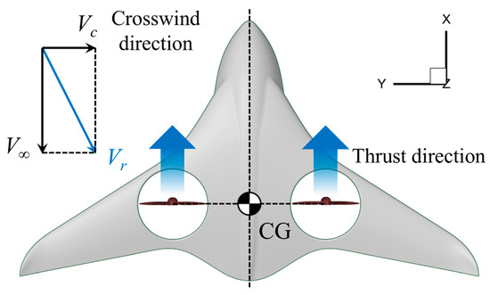
Figure 11.
Definition of the center of gravity and the positive direction of crosswind velocity.
As shown in Figure 12a, the lateral moment coefficient variations with crosswind velocity (Vc) revealed that, while the CNIU configuration maintained similar trends to the no propeller configuration, the CNOU configuration exhibited a 31.5% steeper gradient in lateral moment coefficient sensitivity, indicating improved lateral stability. Similarly, Figure 12b shows the directional moment coefficient variations, where both the CNIU and CNOU configurations demonstrated an approximate 15.6% increase in gradient magnitudes compared to the no propeller configuration. These differential responses are attributed to distinct vortex interaction mechanisms caused by the different propeller rotation directions.
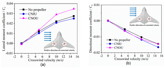
Figure 12.
Lateral–directional static moment coefficient curves with crosswind velocity. (a) Lateral moment coefficient; (b) directional moment coefficient.
To better understand the aerodynamic interference between the propellers and the hybrid wing aircraft, an investigation is conducted into the pressure distributions across the outboard wing sections under crosswind conditions. Figure 13 presents pressure coefficient profiles at two critical spanwise stations: the directly affected section (y/b/2 = +0.7, Figure 13a) and the indirectly affected section (y/b/2 = −0.7, Figure 13b). Under crosswind-free conditions, symmetrical pressure distributions were observed between the left and right wings. When a 10 m/s leftward crosswind was applied, the left wing experienced an increase in effective incidence, while the right wing experienced a reduction. This generated a stabilizing rightward rolling moment, thereby improving lateral static stability.
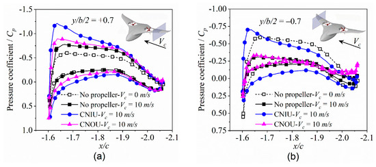
Figure 13.
Pressure coefficient curves at different sides cross sections of the wing. (a) Cp at the section of y/b/2 = +0.7; (b) Cp at the section of y/b/2 = −0.7.
Propeller-induced flow modifications significantly altered the pressure characteristics of the outboard wings. The CNIU configuration is found to reduce the lift difference between both wings relative to the CNOU configuration, as the CNIU configuration induced greater lift increments on the left wing. This aerodynamic behavior indicated that the CNOU configuration contributed to a more pronounced rightward rolling tendency, thus providing enhanced lateral static stability during leftward crosswind conditions.
For hybrid wing aircraft, stability during the transition flight phase is of paramount importance. Intense, unsteady interactions between the propeller slipstream and the surrounding airflow over the aircraft are driven by rotors at varying tilt angles—challenges that traditional quasi-steady methods fail to fully capture. Therefore, developing flight dynamics models that explicitly account for slipstream effects, alongside efficient, high-fidelity unsteady CFD methodologies, offers substantial research potential. Additionally, leveraging multidisciplinary design optimization and neural network techniques constitutes a key direction for future advancement in this field.
5. Conclusions
This study investigates the aerodynamic interaction between propellers and aircraft in relation to aerodynamic performance and flight stability by establishing three distinct propeller configuration models—no propeller, CNIU, and CNOU. The main findings are summarized as follows:
- (1)
- Propeller-induced slipstream significantly impacts the aerodynamic characteristics of hybrid wing aircraft. The CNIU configuration was found to enhance the low-pressure area coverage on both the fuselage and outer wing upper surfaces, which was attributed to the deviations of crossflow velocity. This resulted in an increment in the lift-to-drag ratio by approximately 28.4% at low angles of attack, improving cruising flight efficiency.
- (2)
- The CNOU configuration improves the longitudinal steady-static margin by 27.4% under typical conditions. Under a crosswind velocity of 10 m/s, the CNOU configuration exhibited superior lateral–directional static stability, with a 31.5% steeper slope in the lateral moment coefficient curve compared to the CNIU configuration, indicating superior crosswind resistance and flight stability.
- (3)
- The internal wing holes reduced the wing area and caused local lift loss in the surrounding region. In contrast, the aerodynamic interaction of the embedded propeller mitigated the extension of this lift loss aera. Furthermore, other studies indicate that a further drag decrement can be achieved via aerodynamic shaping of the holes, which has improved the meaning of engineering applications.
- (4)
- Distinct propeller rotation directions provide unique aerodynamic benefits. The CNIU configuration, with its aerodynamic advantages, improves energy utilization efficiency. With the continued development of active control technologies, this configuration holds great engineering potential for future applications.
Author Contributions
Conceptualization, X.W. and C.C.; methodology, Z.J.; software, J.L.; validation, C.C.; formal analysis, C.C.; investigation, Z.J.; resources, Z.J.; data curation, C.C. and J.L.; writing—original draft preparation, X.W. and C.C.; writing—review and editing, Z.J. and J.L.; visualization, C.C. and Z.J.; supervision, X.W. and K.Z.; project administration, X.W. and K.Z.; funding acquisition, X.W. and K.Z. All authors have read and agreed to the published version of the manuscript.
Funding
This research was funded by the Foundation of National Key Laboratory of Aircraft Configuration Design (Grant number: JBGS-202501) and the Foundation of Henan Key Laboratory of General Aviation Technology (Grant number: ZHKF-230201, ZHKF-240202, and ZHKF-240211).
Data Availability Statement
Data is contained within the article.
Conflicts of Interest
The authors declare no conflicts of interest.
Nomenclatures and Abbreviations
| Nomenclatures | |
| b | Wingspan, m. |
| β | Blade pitch angle, deg. |
| c | Chord length, m. |
| CL | Lift coefficient. |
| CD | Drag coefficient. |
| Cp | Pressure coefficient, (p − p∞)/q∞. |
| CT | Thrust coefficient, T/(ρn2D4). |
| CQ | Torque coefficient, Q/(ρn2D5). |
| Cm | Longitudinal static moment coefficient. |
| Cl | Lateral static moment coefficient. |
| Cn | Directional static moment coefficient. |
| D | Propeller diameter, m. |
| J | Propeller advance ratio. |
| K | Lift-to-drag ratio, CL/CD. |
| l | Wingspan length, m. |
| n | Rotational speed of propeller, rev/s. |
| N | Blade number of propeller. |
| p | Static pressure, N/m2. |
| p∞ | Freestream pressure, N/m2. |
| ρ | Freestream air density, kg/m3. |
| q∞ | Dynamic pressure, N/m2. |
| R | Propeller radius, m. |
| r | Radial coordinate, m. |
| S | Wing area, m2. |
| V∞ | Freestream velocity, m/s. |
| Va | Axial velocity of slipstream, m/s. |
| Vr | Resultant velocity, m/s. |
| Vt | Tangent velocity of slipstream, m/s. |
| Vc | Crosswind velocity, m/s. |
| y+ | Dimensionless wall distance. |
| x, y, z | Grid coordinates, m. |
| Abbreviations | |
| AOA | Angle of attack. |
| BWB | Blended-wing-body. |
| CFD | Computational fluid dynamics. |
| CG | Center of gravity. |
| CNIU | Counter-rotating inboard-upwash configuration. |
| CNOU | Counter-rotating outboard-upwash configuration. |
| eVTOL | Electric vertical take-off and landing. |
| HLP | High-lift propeller. |
| MRF | Multiple reference frame. |
| RANS | Reynolds-averaged Navier–Stokes equations. |
| RPM | Revolutions per minute. |
| SMM | Sliding mesh model. |
| UAM | Urban air mobility. |
References
- Ugwueze, O.; Statheros, T.; Bromfield, M.A.; Horri, N. Trends in eVTOL aircraft development: The concepts, enablers and challenges. In Proceedings of the AIAA SCITECH 2023 Forum, Online & National Harbor, MD, USA, 23 January 2023; pp. 2023–2096. [Google Scholar] [CrossRef]
- Straubinger, A.; Rothfeld, R.; Shamiyeh, M.; Büchter, K.D.; Kaiser, J.; Plötner, K.O. An overview of current research and developments in urban air mobility—Setting the scene for UAM introduction. J. Air Transp. Manag. 2020, 87, 101852. [Google Scholar] [CrossRef]
- Gohardani, A.S.; Doulgeris, G.; Singh, R. Challenges of future aircraft propulsion: A review of distributed propulsion technology and its potential application for the all electric commercial aircraft. Prog. Aerosp. Sci. 2011, 47, 369–391. [Google Scholar] [CrossRef]
- Chen, Z.L.; Zhang, M.H.; Chen, Y.C.; Sang, W.M.; Tan, Z.G.; Li, D.; Zhang, B.Q. Assessment on critical technologies for conceptual design of blended-wing-body civil aircraft. Chin. J. Aeronaut. 2019, 32, 1797–1827. [Google Scholar] [CrossRef]
- Green, J.E. Greener by design—The technology challenge. Aeronaut. J. 2002, 106, 57–113. [Google Scholar] [CrossRef]
- Arora, A.; Das, S.; Kumar, P. Flow field investigation of a blended wing body in low speeds. J. Appl. Fluid Mech. 2023, 16, 794–804. [Google Scholar] [CrossRef]
- Zhang, W.; Zhou, L.; Zhao, K.; Zhang, R.B.; Gao, Z.H.; Shu, B.W. Airfoil design optimization of blended wing body for various aerodynamic and stealth stations. Aerospace 2024, 11, 586. [Google Scholar] [CrossRef]
- Qin, N.; Vavalle, A.; Le Moigne, A.; Laban, M.; Hackett, K.; Weinerfelt, P. Aerodynamic considerations of blended wing body aircraft. Prog. Aerosp. Sci. 2004, 40, 321–343. [Google Scholar] [CrossRef]
- Humphreys-Jennings, C.; Lappas, I.; Sovar, D.M. Conceptual design, flying, and handling qualities assessment of a blended wing body (BWB) aircraft by using an engineering flight simulator. Aerospace 2020, 7, 51. [Google Scholar] [CrossRef]
- Wang, L.X.; Zhang, N.; Liu, H.L.; Yue, T. Stability characteristics and airworthiness requirements of blended wing body aircraft with podded engines. Chin. J. Aeronaut. 2022, 35, 77–86. [Google Scholar] [CrossRef]
- Wang, L.X.; Zhang, N.; Yue, T.; Liu, H.L.; Zhu, J.H.; Jia, X.P. Three-axis coupled flight control law design for flying wing aircraft using eigenstructure assignment method. Chin. J. Aeronaut. 2020, 33, 2510–2526. [Google Scholar] [CrossRef]
- Song, L.; Yang, H.; Zhang, Y.; Zhang, H.Y.; Huang, J. Dihedral influence on lateral–directional dynamic stability on large aspect ratio tailless flying wing aircraft. Chin. J. Aeronaut. 2014, 27, 1149–1155. [Google Scholar] [CrossRef]
- Khattak, A.; Zhang, J.; Chan, P.W.; Chen, F.; Almujibah, H. Assessment of crosswind speed over the runway glide path using an interpretable local cascade ensemble approach aided by wind tunnel experiments. Atmosphere 2023, 14, 1561. [Google Scholar] [CrossRef]
- Ryu, M.; Cho, L.; Cho, J. Aerodynamic analysis of the ducted fan for a VTOL UAV in crosswinds. Trans. Jpn. Soc. Aeronaut. Space Sci. 2016, 59, 47–55. [Google Scholar] [CrossRef]
- Luo, Y.W.; Ai, T.F.; He, Y.H.; Xu, B.; Qian, Y.P.; Zhang, Y.J. Numerical analysis of wind effects on aerodynamic characteristics of a ducted fan. Chin. J. Aeronaut. 2024, 37, 263–280. [Google Scholar] [CrossRef]
- Zhao, W.Y.; Zhang, Y.L.; Tang, P.; Wu, J.H. The impact of distributed propulsion on the aerodynamic characteristics of a blended-wing-body aircraft. Aerospace 2022, 9, 704. [Google Scholar] [CrossRef]
- Wang, K.L.; Zhou, Z. Aerodynamic design, analysis and validation of a small blended-wing-body unmanned aerial vehicle. Aerospace 2022, 9, 36. [Google Scholar] [CrossRef]
- Shen, Z.S.; Liu, F. Design and implementation of a novel tilt-rotor tri-copter UAV configuration. Eng. Proc. 2025, 80, 39. [Google Scholar] [CrossRef]
- Qiao, Z.; Wang, D.; Xu, J.H.; Pei, X.B.; Su, W.; Wang, D.; Bai, Y. A comprehensive design and experiment of a biplane quadrotor tail-sitter UAV. Drones 2023, 7, 292. [Google Scholar] [CrossRef]
- Raja, V.; Murugesan, R.; Solaiappan, S.K.; Arputharaj, B.S.; Rajendran, P.; AL-bonsrulah, H.A.Z.; Thakur, D.; Razak, A.; Buradi, A.; Ketema, A. Design, computational aerodynamic, aerostructural, and control stability investigations of VTOL-configured hybrid blended wing body-based unmanned aerial vehicle for intruder inspections. Int. J. Aerosp. Eng. 2023, 2023, 9699908. [Google Scholar] [CrossRef]
- Parisa, F.; Adrien, B.; Sergey, S. Aerodynamic characteristics of the blended-wing-body VTOL UAV. J. Aerosp. Eng. Mech. 2020, 4, 187–200. [Google Scholar] [CrossRef]
- Liu, J.; Li, G.; Ma, D.; Wang, F. Aerodynamic interference and wake characteristics of a multirotor tandem tilt-wing electric vertical take-off and landing aircraft in conversion flight. Phys. Fluids 2025, 37, 115127. [Google Scholar] [CrossRef]
- Wu, D.; Mo, C.S.; Chen, J.H.J.; Lu, Z.B. Longitudinal static stability and trim conditions analysis of eVTOL in steady level flight based on CFD and ducted-fan test. In Proceedings of the 2025 IEEE 26th China Conference on System Simulation Technology and its Applications (CCSSTA), Shenzhen, China, 11 July 2025; pp. 127–131. [Google Scholar] [CrossRef]
- Wang, X.L.; Liu, W.W.; Chen, C.N.; Liu, Y.Y. Rotor position aerodynamics research of a hybrid configuration electric UAV. Aircr. Eng. Aerosp. Technol. 2025, 97, 739–749. [Google Scholar] [CrossRef]
- Liang, Y.; Shan, X.; Wang, Z.; Zheng, Q. Propeller installation effect and surrogate based optimization of a tail-sitter drone. In Proceedings of the AIAA AVIATION 2022 Forum, Online & Chicago, IL, USA, 27 June 2022; pp. 2022–3379. [Google Scholar] [CrossRef]
- Arumugam, V.R.; Chidambaram, S. Aerodynamic effects of propeller slipstream on a transition micro aerial vehicle under various maneuvering conditions. Phys. Fluids 2025, 37, 015121. [Google Scholar] [CrossRef]
- Figat, M.; Piątkowska, P. Numerical investigation of mutual interaction between a pusher propeller and a fuselage. Proc. Inst. Mech. Eng. Part G J. Aerosp. Eng. 2021, 235, 40–53. [Google Scholar] [CrossRef]
- Guo, J.; Zhou, Z. An efficient blade design method of a ducted fan coupled with the CFD modification. Aerospace 2022, 9, 241. [Google Scholar] [CrossRef]
- Ai, T.; Fan, W.; Xu, B.; Xiang, C.; Zhang, Y.; Zhao, Z. Aerodynamic analysis and modeling of coaxial ducted fan aircraft with the ceiling effect. Eng. Appl. Comput. Fluid Mech. 2021, 15, 1563–1584. [Google Scholar] [CrossRef]
- Electric VTOL News, Project Zero. Available online: https://evtol.news/news/project-zero (accessed on 28 December 2025).
- Aktas, Y.O.; Ozdemir, U.; Dereli, Y.; Tarhan, A.F.; Cetin, A.; Vuruskan, A.; Yuksek, B.; Cengiz, H.; Basdemir, S.; Ucar, M.; et al. A low cost prototyping approach for design analysis and flight testing of the TURAC VTOL UAV. In Proceedings of the 2014 International Conference on Unmanned Aircraft Systems (ICUAS), Orlando, FL, USA, 27–30 May 2014; pp. 1029–1039. [Google Scholar] [CrossRef]
- Sikorsky Cypher, Sikorsky Product History. Available online: https://www.sikorskyarchives.com/CYPHER.php (accessed on 28 December 2025).
- Liu, X.R.; Zhao, D.; Oo, N.L. Comparison studies on aerodynamic performances of a rotating propeller for small-size UAVs. Aerosp. Sci. Technol. 2023, 133, 108148. [Google Scholar] [CrossRef]
- Silva, P.A.S.F.; Tsoutsanis, P.; Antoniadis, A.F. Simple multiple reference frame for high-order solution of hovering rotors with and without ground effect. Aerosp. Sci. Technol. 2021, 111, 106518. [Google Scholar] [CrossRef]
- Liu, W.W.; Wang, X.L.; Li, J.H.; Liu, D.J.; Luo, M.Q. Effects of propulsion type on the cruise aerodynamic performance and stability of electric vertical take-off and landing aircraft: A comparative study. Aerosp. Syst. 2025. [Google Scholar] [CrossRef]
- Walvekar, O.; Chakravarthy, S. An unsteady Reynolds–Averaged Navier–Stokes–large eddy simulation study of propeller–airframe interaction in distributed electric propulsion. Aerospace 2023, 11, 17. [Google Scholar] [CrossRef]
- Zhao, S.; Li, J.; Yang, Z.; Qian, R.Z.; Xu, R.F. Propeller rotation effects on pitching moment for transport aircraft with conventional tail. J. Aircr. 2023, 60, 789–799. [Google Scholar] [CrossRef]
- Litherland, B.L.; Borer, N.K.; Zawodny, N.S. X-57 “Maxwell” high-lift propeller testing and model development. In Proceedings of the AIAA Aviation 2021 Forum, Virtual, 2 August 2021; pp. 2021–3193. [Google Scholar] [CrossRef]
- Borer, N.K.; Patterson, M.D. X-57 high-lift propeller control schedule development. In Proceedings of the AIAA Aviation 2020 Forum, Virtual, 15 June 2020; pp. 2020–3091. [Google Scholar] [CrossRef]
- Litherland, B.; Borer, N.; Zawodny, N.; Frederick, Z. X-57 “Maxwell” high-lift propeller test for improved thrust measurements and slipstream velocities. In Proceedings of the 2022 AIAA Aviation Forum, Chicago, IL, USA, 28 June 2022; Available online: https://ntrs.nasa.gov/api/citations/20220006506/downloads/LSAWT-015%20Test%20Summary%20Aviation%202022%20Final.pdf (accessed on 28 December 2025).
- Chirico, G.; Barakos, G.N.; Bown, N. Propeller installation effects on turboprop aircraft acoustics. J. Sound Vib. 2018, 424, 238–262. [Google Scholar] [CrossRef]
- Sawaqed, L.; Bani Younes, A.; Aldalal’ah, M. Aerodynamics effect of holes in UAV wings modified for VTOL capability. Drone Syst. Appl. 2022, 10, 330–342. [Google Scholar] [CrossRef]
- Hoeveler, B.; Bauknecht, A.; Christian Wolf, C.; Janser, F. Wind-tunnel study of a wing-embedded lifting fan remaining open in cruise flight. J. Aircr. 2020, 57, 558–568. [Google Scholar] [CrossRef]
- Chen, C.N.; Wang, X.L.; Liu, W.W.; Li, Q.S. Aerodynamic simulation of a cargo UAV with twin-boom and rear-mounted propeller. In Proceedings of the 2023 Asia-Pacific International Symposium on Aerospace Technology (APISAT 2023), Lingshui, China, 16–18 October 2023; Fu, S., Ed.; 2024; Volume 1051, pp. 1490–1503. [Google Scholar] [CrossRef]


Disclaimer/Publisher’s Note: The statements, opinions and data contained in all publications are solely those of the individual author(s) and contributor(s) and not of MDPI and/or the editor(s). MDPI and/or the editor(s) disclaim responsibility for any injury to people or property resulting from any ideas, methods, instructions or products referred to in the content. |
© 2026 by the authors. Licensee MDPI, Basel, Switzerland. This article is an open access article distributed under the terms and conditions of the Creative Commons Attribution (CC BY) license.